EP2246257A1 - Multi-section connecting region of a flexbeam - Google Patents
Multi-section connecting region of a flexbeam Download PDFInfo
- Publication number
- EP2246257A1 EP2246257A1 EP09400018A EP09400018A EP2246257A1 EP 2246257 A1 EP2246257 A1 EP 2246257A1 EP 09400018 A EP09400018 A EP 09400018A EP 09400018 A EP09400018 A EP 09400018A EP 2246257 A1 EP2246257 A1 EP 2246257A1
- Authority
- EP
- European Patent Office
- Prior art keywords
- connection point
- flexbeam
- fastening
- connecting region
- fastening attachments
- Prior art date
- Legal status (The legal status is an assumption and is not a legal conclusion. Google has not performed a legal analysis and makes no representation as to the accuracy of the status listed.)
- Granted
Links
Images
Classifications
-
- B—PERFORMING OPERATIONS; TRANSPORTING
- B64—AIRCRAFT; AVIATION; COSMONAUTICS
- B64C—AEROPLANES; HELICOPTERS
- B64C27/00—Rotorcraft; Rotors peculiar thereto
- B64C27/32—Rotors
- B64C27/33—Rotors having flexing arms
-
- B—PERFORMING OPERATIONS; TRANSPORTING
- B64—AIRCRAFT; AVIATION; COSMONAUTICS
- B64C—AEROPLANES; HELICOPTERS
- B64C27/00—Rotorcraft; Rotors peculiar thereto
- B64C27/32—Rotors
- B64C27/46—Blades
- B64C27/473—Constructional features
- B64C27/48—Root attachment to rotor head
Definitions
- the invention relates to a connecting region of a flexbeam according to the preamble of claim 1.
- a flexbeam has a connecting region by which means this is firmly connected to the rotor head.
- the flexbeam is provided with a transition region at which a rotor blade is fastened.
- a flexbeam is also characterised by the fact that it has regions of reduced stiffness. A region of reduced stiffness, for example, allows bending about the chord and is designated as impact axis.
- a commonly used implementation of the fastening of the flexbeam on the rotor head consists in providing the connecting region with two loop-shaped connection points which serve to accommodate bolts.
- the bolts are inserted vertically through the rotor head and the loop-shaped connection points of the flexbeam for fastening and thus fix these in a torque-proof and pivot-proof manner on the rotor head.
- the flexbeams are disposed peripherally on the rotor head in such a manner that, for example, in each case one bolt passes through the respective connection point.
- the flexbeams attached in this manner peripherally in the rotor plane on the rotor head are located adjacent to one another and are usually fixed by bolts or fastening means at twice as many connection points as provided flexbeams.
- connecting regions which can be fixed in a plane on the rotor head with at least two bolts per flexbeam. This makes it possible to achieve a symmetrical configuration of the connecting region and provides a uniform stiffness distribution over the profile plane but offers less potential for reducing the impact axis distance.
- DE 103 16 094 A1 discloses a connecting region of a flexbeam in which the connecting region completely encloses the rotor mast and absorbs the centrifugal forces. The torque is transmitted to the ends pointing away from the rotor blade. All the rotor blades lie one above the other. For exchanging the lowermost rotor blade or blade connection, all those located thereabove must also be dismounted.
- the impact axis distance is the distance of the axis of the "fictitious" flapping hinge of the flexbeam from the rotor centre. This can be made possible by making the rotor head smaller. In order to achieve this, unlike the hitherto usual rotor head in which each connecting region is fastened with two bolts assigned exclusively to the two connection points, it is known to make respectively two connection points of the successive flexbeams overlap and thereby halve the number of bolts required. As a result, the total diameter of the rotor head can be reduced significantly. In this case, each bolt connects two connection points of two successive flexbeams to the rotor head.
- connection points are configured in such a manner that a first connection point comprises two loops which are spaced apart in the vertical direction and the second connection point comprises two loops which lie together. In the mounted state the spaced-apart loops embrace the lying-together loops of the subsequent or the previous flexbeam.
- the invention is based on the finding that the strength is increased by sandwich structures without necessarily incurring an increase in the material thickness. In addition, asymmetry in the stiffness is reduced by the multi-section property.
- a connecting region of a flexbeam comprises a first and a second connection point which lie largely along a line running orthogonally to the radial extension of the rotor head, each connection point being split into fastening attachments in the vertical direction.
- the fastening attachments have a circular recess for receiving a bolt wherein these lie coaxially above one another per connection point, so that a fastening means/bolt can be guided through all the fastening attachments of a connection point.
- the first connection point has at least two fastening attachments which are spaced apart from one another in the vertical direction.
- the second connection point is provided with at least three fastening attachments which are spaced apart from one another in the vertical direction.
- the second connection point is always provided with at least one fastening attachment more than the first connection point.
- connection points A multi-sectional introduction of forces is thereby made possible, with the result that the strength of the rotor mounting is significantly increased.
- Another major advantage resulting from the multi-sectional nature of the connection points is the stiffness distribution along a line aligned orthogonally to the radial extension of the rotor head. In contrast to the previous prior art, the difference in stiffness between the two regions of the connection points is significantly reduced since the differences in the angle of spread which crucially influence the stiffness are significantly reduced compared with the prior art.
- the fraction of the region of the second connection point in the total stiffness is about 90% whereas with a connecting region according to the invention, the fraction of the region of the second connection point comprises about 60% of the total stiffness.
- the fastening attachments are disposed in such a manner than in a peripheral intermeshing arrangement of the flexbeam, the fastening attachments of the first connection point intermesh with fastening attachments of the second connection point in the vertical and horizontal direction.
- the connection points are embraced by the rotor head.
- all fastening attachments of the first connection point are preferably bordered on both sides by fastening attachments of the second connection point. In this way, at least one fastening attachment of the second connection point lies both over and under each fastening attachment of the first connection point. As a result, the strength is decisively increased.
- the fastening attachments of the connection points are formed from a fibre composite. This has a sufficient strength with low weight. It is particularly advantageous to form this directly on the torsional element of the flexbeam.
- the upper fastening attachment of the first connection point and the upper fastening attachment of the second connection point can be formed from the same material.
- the lower fastening attachment of the first and the second connection point can be formed from the same material ply. This considerably simplifies the manufacture of the flexbeam.
- middle fastening attachments are formed from different material plies. An increase in strength is thus achieved.
- the fastening attachments are preferably configured as loop-shaped. This allows anchoring of the fastening attachments in the flexbeam and excellent multi-sectional introduction of forces.
Landscapes
- Engineering & Computer Science (AREA)
- Mechanical Engineering (AREA)
- Aviation & Aerospace Engineering (AREA)
- Wind Motors (AREA)
Abstract
Description
- The invention relates to a connecting region of a flexbeam according to the preamble of claim 1.
- It is known that bearingless rotors have no hinges on the rotor head. The previously real hinges are replaced by a so-called flexbeam in this design and externalised into "fictitious hinges". A flexbeam has a connecting region by which means this is firmly connected to the rotor head. In addition, the flexbeam is provided with a transition region at which a rotor blade is fastened. A flexbeam is also characterised by the fact that it has regions of reduced stiffness. A region of reduced stiffness, for example, allows bending about the chord and is designated as impact axis.
- A commonly used implementation of the fastening of the flexbeam on the rotor head consists in providing the connecting region with two loop-shaped connection points which serve to accommodate bolts. The bolts are inserted vertically through the rotor head and the loop-shaped connection points of the flexbeam for fastening and thus fix these in a torque-proof and pivot-proof manner on the rotor head.
- In an embodiment already in series production, the flexbeams are disposed peripherally on the rotor head in such a manner that, for example, in each case one bolt passes through the respective connection point. The flexbeams attached in this manner peripherally in the rotor plane on the rotor head are located adjacent to one another and are usually fixed by bolts or fastening means at twice as many connection points as provided flexbeams.
- This is also reflected in the documents
US 5 738 494 ,US 5 372 479 and Int. J. Engng Ed. Vol. 13, No. 5, p. 369-375, 1997. Shown there are connecting regions which can be fixed in a plane on the rotor head with at least two bolts per flexbeam. This makes it possible to achieve a symmetrical configuration of the connecting region and provides a uniform stiffness distribution over the profile plane but offers less potential for reducing the impact axis distance. -
DE 103 16 094 A1 discloses a connecting region of a flexbeam in which the connecting region completely encloses the rotor mast and absorbs the centrifugal forces. The torque is transmitted to the ends pointing away from the rotor blade. All the rotor blades lie one above the other. For exchanging the lowermost rotor blade or blade connection, all those located thereabove must also be dismounted. -
US 4 746 272 ,US 4 898 515 ,CA 2411533C andUS 6 708 921 describe a connecting region of a flexbeam which forms the connecting region of a second opposite flexbeam in the structural unit. This has the disadvantage that maintenance is expensive since two flexbeams always need to be changed concomitantly. In addition, due to the pairwise configuration it is not possible to provide an odd number of rotor blades. - From the flight-dynamic viewpoint, it is desirable to minimise the impact axis distance. The impact axis distance is the distance of the axis of the "fictitious" flapping hinge of the flexbeam from the rotor centre. This can be made possible by making the rotor head smaller. In order to achieve this, unlike the hitherto usual rotor head in which each connecting region is fastened with two bolts assigned exclusively to the two connection points, it is known to make respectively two connection points of the successive flexbeams overlap and thereby halve the number of bolts required. As a result, the total diameter of the rotor head can be reduced significantly. In this case, each bolt connects two connection points of two successive flexbeams to the rotor head. The connection points are configured in such a manner that a first connection point comprises two loops which are spaced apart in the vertical direction and the second connection point comprises two loops which lie together. In the mounted state the spaced-apart loops embrace the lying-together loops of the subsequent or the previous flexbeam.
- This arrangement of the rotor blades is deduced from ECD 0158-06-PUB published at the Annual Meeting of the DGLR in Braunschweig in November 2006 as "Advanced Technology Rotor" ATR. This configuration achieves an improvement in the dynamic properties but has strength problems in the connection region as a consequence.
- It is the object of the invention, whilst avoiding the aforesaid disadvantages, to provide a flexbeam with a connecting region which has a short impact axis distance and a high strength in the connecting region and ensures a high flexibility during maintenance.
- The invention is based on the finding that the strength is increased by sandwich structures without necessarily incurring an increase in the material thickness. In addition, asymmetry in the stiffness is reduced by the multi-section property.
- This object is achieved by the characterising features of claim 1 in conjunction with the features of its preamble.
- The dependent claims form advantageous further developments of the invention.
- In a known manner, a connecting region of a flexbeam comprises a first and a second connection point which lie largely along a line running orthogonally to the radial extension of the rotor head, each connection point being split into fastening attachments in the vertical direction. The fastening attachments have a circular recess for receiving a bolt wherein these lie coaxially above one another per connection point, so that a fastening means/bolt can be guided through all the fastening attachments of a connection point. Conventionally in a peripherally overlapping arrangement of a plurality of flexbeams on a rotor head, in each case the first connection point engages in the second connection point of a following flexbeam in such a manner that the recesses of the fastening attachments of the first connection point lie coaxially above the recesses of the fastening attachments of the associated second connection point.
- According to the invention, the first connection point has at least two fastening attachments which are spaced apart from one another in the vertical direction. The second connection point is provided with at least three fastening attachments which are spaced apart from one another in the vertical direction. The second connection point is always provided with at least one fastening attachment more than the first connection point.
- A multi-sectional introduction of forces is thereby made possible, with the result that the strength of the rotor mounting is significantly increased. Another major advantage resulting from the multi-sectional nature of the connection points is the stiffness distribution along a line aligned orthogonally to the radial extension of the rotor head. In contrast to the previous prior art, the difference in stiffness between the two regions of the connection points is significantly reduced since the differences in the angle of spread which crucially influence the stiffness are significantly reduced compared with the prior art.
- In the prior art, for example, the fraction of the region of the second connection point in the total stiffness is about 90% whereas with a connecting region according to the invention, the fraction of the region of the second connection point comprises about 60% of the total stiffness.
- The fastening attachments are disposed in such a manner than in a peripheral intermeshing arrangement of the flexbeam, the fastening attachments of the first connection point intermesh with fastening attachments of the second connection point in the vertical and horizontal direction. The connection points are embraced by the rotor head.
- Due to the intermeshing arrangement, a reduction in the rotor head diameter is achieved. This results in the desired reduction of the impact axis distance. Due to the multiple overlapping of the loops of two successive rotor blades, the strength is increased without necessitating an enlargement in cross-section. An enlargement in cross-section would result in an increase in the stiffness of the flexbeam which in turn would lead to an undesirably large impact axis distance.
- In a peripheral arrangement, all fastening attachments of the first connection point are preferably bordered on both sides by fastening attachments of the second connection point. In this way, at least one fastening attachment of the second connection point lies both over and under each fastening attachment of the first connection point. As a result, the strength is decisively increased.
- According to a further advantageous embodiment, the fastening attachments of the connection points are formed from a fibre composite. This has a sufficient strength with low weight. It is particularly advantageous to form this directly on the torsional element of the flexbeam.
- In particular, the upper fastening attachment of the first connection point and the upper fastening attachment of the second connection point can be formed from the same material. In the same way, the lower fastening attachment of the first and the second connection point can be formed from the same material ply. This considerably simplifies the manufacture of the flexbeam.
- It is particularly advantageous if the middle fastening attachments are formed from different material plies. An increase in strength is thus achieved.
- The fastening attachments are preferably configured as loop-shaped. This allows anchoring of the fastening attachments in the flexbeam and excellent multi-sectional introduction of forces.
- Further advantages, features and possible applications of the present invention are obtained from the following description in conjunction with the exemplary embodiments shown in the drawings.
- The invention is described in detail hereinafter with reference to the exemplary embodiments shown in the drawings. The terms and associated reference numerals used in the list of reference numerals given hereinafter are used in the description, in the claims and in the drawings.
- In the drawings:
- Fig. 1
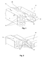
- shows a section of a schematically depicted connecting region of a flexbeam in perspective view;
- Fig. 2
- shows a schematic diagram of two successive flexbeams in perspective view;
- Fig. 3
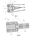
- shows a schematic plan view of the connecting region of a flexbeam;
- Fig. 4a
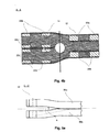
- shows a cross-section through a flexbeam having a connecting region according to the prior art;
- Fig. 4b
- shows a cross-section through a flexbeam having a connecting region according to the invention;
- Fig. 5a
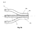
- shows a schematic sectional view of the first connection point of the flexbeam according to the invention;
- Fig. 5b
- shows a schematic sectional view of the second connection point of the flexbeam according to the invention.
-
Figure 1 shows a schematic perspective view of a connectingregion 10 of a flexbeam.Fastening attachments 16 of afirst connection point 12 as well asfastening attachments 18 of asecond connection point 14 are shown. Thefastening attachments fastening attachments fastening attachments fastening attachments -
Figure 2 shows a schematic diagram of two successive connectingregions 10, 10' of identical flexbeams in intermeshing arrangement. In this case, thefastening attachments 16 of thefirst connection point 12 of the first flexbeam engage in the fastening attachments 18' of the second connection point 14' of the second flexbeam 10'. The recesses of thefastening attachments -
Figure 3 shows a plan view of a connectingregion 10 of a flexbeam. This comprises afirst connection point 12 and asecond connection point 14. The loop-shaped configuration of the fastening attachments can be seen particularly clearly in this figure. Theloop arms Figures 4a and4b show cross-sections along the line of intersection A. -
Figure 4a shows a sectional view along the line of intersection A of a flexbeam according to the prior art. Thefastening attachments loop arms first connection point 12 has twoloop arms second connection point 14 is provided with two vertically spacedloop arms first connection point 12 and 92% at thesecond connection point 14. -
Figure 4b shows the schematic sectional view along the line of intersection A of a flexbeam according to the invention. In this diagram thefirst connection point 12 is provided with two vertically spacedloop arms second connection point 14 comprises threeloop arms first connection point 12 and 63% at thesecond connection point 14. It is shown that with the arrangement of thefastening attachments -
Figure 5a shows a schematic section along the line of intersection B. It can be seen very clearly here that contrary to the prior art, thefirst connection point 12 is divided into two spaced-apart fastening attachments. These are each spread at the angle of spread a from the centre line. In general, the angle of spread is crucial for the stiffness E1. Since the first connection point is already spread contrary to the prior art, the difference from the angle of spread β of thesecond connection point 14 is reduced and ensures a more uniform stiffness distribution. -
Figure 5b shows a schematic sectional view along the line of intersection C. In this case, thesecond connection point 14 is divided into threefastening attachments 18. The fastening attachments are formed by theloop arms loop arms loop arm 22c. -
- 10
- Connecting region
- 12
- First connection point
- 14
- Second connection point
- 16
- Fastening attachment of first connection point
- 18
- Fastening attachment of second connection point
- 10'
- Connecting region
- 14'
- Second connection point
- 18'
- Fastening attachment of second connection point
- 20a
- Loop arm
- 20b
- Loop arm
- 22a
- Loop arm
- 22b
- Loop arm
- 22c
- Loop arm
- α
- Angle of spread - first connection point
- β
- Angle of spread - second connection point
- A
- Line of intersection A-A
- B
- Line of intersection B-B
- C
- Line of intersection C-C
- L
- Line
- R
- Radial extension
Claims (7)
- A flexbeam having a connecting region (10) for connection to a rotor head, wherein the connecting region (10) comprises a first connection point (12) and a second connection point (14), which lie adjacent to one another along a line (L) lying perpendicular to the radial extension (R) of the rotor head at the end of the flexbeam facing the rotor head,
characterised in that the first connection point (12) comprises at least two fastening attachments (16) located one above the other and spaced vertically apart from one another, which have circular recesses, wherein the fastening attachments (16) are aligned in such a manner that the recesses lie coaxially with respect to one another and the second connection point (14) is provided with at least one more fastening attachment (18) than the first connection point (12), wherein the fastening attachments (18) of the second connection point (14), which are spaced apart in the vertical direction and lie one above the other, are likewise aligned in such a manner than their coaxial recesses lie coaxially with respect to one another. - A flexbeam according to claim 1,
characterised in that the first connection point (12) of the connecting region (10) of a first flexbeam and the second connection point (14') of the connecting region (10') of an identical second flexbeam which lies adjacent to the first flexbeam in the mounted state, intermesh. - A flexbeam according to claim 2,
characterised in that all the fastening attachments (16) of a first connection point (12) can be enclosed on both sides in the vertical direction by fastening attachments (18') of the second connection point (14'). - A flexbeam according to claim 1,
characterised in that all the fastening attachments (14, 16) are formed from the fibre composite material of the flexbeam. - A flexbeam according to one of the preceding claims,
characterised in that the fastening attachments (16, 18) of the two connection points (12, 14) located vertically at the top are formed from a first ply, the fastening attachments (16, 18) of the two connection points (12, 14) located at the bottom are formed from a second ply. - A flexbeam according to one of the preceding claims,
characterised in that the middle fastening attachment (18) of the second connection point (14) is formed from two different plies. - A flexbeam according to one of the preceding claims,
characterised in that the fastening attachments (16, 18) are formed as loop-shaped.
Priority Applications (1)
| Application Number | Priority Date | Filing Date | Title |
|---|---|---|---|
| EP09400018.9A EP2246257B1 (en) | 2009-04-29 | 2009-04-29 | Multi-section connecting region of a flexbeam |
Applications Claiming Priority (1)
| Application Number | Priority Date | Filing Date | Title |
|---|---|---|---|
| EP09400018.9A EP2246257B1 (en) | 2009-04-29 | 2009-04-29 | Multi-section connecting region of a flexbeam |
Publications (2)
| Publication Number | Publication Date |
|---|---|
| EP2246257A1 true EP2246257A1 (en) | 2010-11-03 |
| EP2246257B1 EP2246257B1 (en) | 2016-02-17 |
Family
ID=41138661
Family Applications (1)
| Application Number | Title | Priority Date | Filing Date |
|---|---|---|---|
| EP09400018.9A Not-in-force EP2246257B1 (en) | 2009-04-29 | 2009-04-29 | Multi-section connecting region of a flexbeam |
Country Status (1)
| Country | Link |
|---|---|
| EP (1) | EP2246257B1 (en) |
Cited By (3)
| Publication number | Priority date | Publication date | Assignee | Title |
|---|---|---|---|---|
| WO2014024128A3 (en) * | 2012-08-07 | 2014-03-27 | Epsilon Engineering Services (Pty) Ltd. | A hinge arrangement |
| CN104071335A (en) * | 2013-03-28 | 2014-10-01 | 空客直升机德国有限公司 | Bar of composite matrix material |
| EP3248870A1 (en) * | 2016-05-25 | 2017-11-29 | AIRBUS HELICOPTERS DEUTSCHLAND GmbH | Multi-blade rotor for a rotary wing aircraft |
Citations (9)
| Publication number | Priority date | Publication date | Assignee | Title |
|---|---|---|---|---|
| US4746272A (en) | 1986-07-23 | 1988-05-24 | United Technologies Corporation | Lobed composite flexbeam |
| US4898515A (en) | 1986-07-23 | 1990-02-06 | United Technologies Corporation | External wrap of composite flexbeam |
| FR2660619A1 (en) * | 1990-04-06 | 1991-10-11 | Agusta Spa | HELICOPTER BLADE. |
| US5228834A (en) * | 1990-04-27 | 1993-07-20 | Kawasaki Jukogyo Kabushiki | Hub structure for a rotary wing aircraft |
| US5372479A (en) | 1993-06-02 | 1994-12-13 | United Technologies Corporation | Flexbeam for a helicopter bearingless main rotor assembly |
| US5738494A (en) | 1996-07-18 | 1998-04-14 | Sikorsky Aircraft Corporation | Optimized composite flexbeam for helicopter rotors |
| US6708921B2 (en) | 2001-04-20 | 2004-03-23 | Bell Helicopter Textron, Inc. | Composite flapping flexure |
| DE10316094A1 (en) | 2003-04-08 | 2004-11-11 | Eurocopter Deutschland Gmbh | Articulated rotor and rotary wing aircraft with such a rotor |
| CA2411533C (en) | 2001-11-08 | 2007-07-03 | Fuji Jukogyo Kabushiki Kaisha | Flexbeam |
-
2009
- 2009-04-29 EP EP09400018.9A patent/EP2246257B1/en not_active Not-in-force
Patent Citations (9)
| Publication number | Priority date | Publication date | Assignee | Title |
|---|---|---|---|---|
| US4746272A (en) | 1986-07-23 | 1988-05-24 | United Technologies Corporation | Lobed composite flexbeam |
| US4898515A (en) | 1986-07-23 | 1990-02-06 | United Technologies Corporation | External wrap of composite flexbeam |
| FR2660619A1 (en) * | 1990-04-06 | 1991-10-11 | Agusta Spa | HELICOPTER BLADE. |
| US5228834A (en) * | 1990-04-27 | 1993-07-20 | Kawasaki Jukogyo Kabushiki | Hub structure for a rotary wing aircraft |
| US5372479A (en) | 1993-06-02 | 1994-12-13 | United Technologies Corporation | Flexbeam for a helicopter bearingless main rotor assembly |
| US5738494A (en) | 1996-07-18 | 1998-04-14 | Sikorsky Aircraft Corporation | Optimized composite flexbeam for helicopter rotors |
| US6708921B2 (en) | 2001-04-20 | 2004-03-23 | Bell Helicopter Textron, Inc. | Composite flapping flexure |
| CA2411533C (en) | 2001-11-08 | 2007-07-03 | Fuji Jukogyo Kabushiki Kaisha | Flexbeam |
| DE10316094A1 (en) | 2003-04-08 | 2004-11-11 | Eurocopter Deutschland Gmbh | Articulated rotor and rotary wing aircraft with such a rotor |
Non-Patent Citations (3)
| Title |
|---|
| BANSEMIR HORST: "Weiterentwicklung des Lagerlosen Rotorsystems der EC 135 zum Advanced Technology Rotor", THEMENHEFT FORSCHUNG, 1 March 2007 (2007-03-01), Stuttgart, pages 26 - 26 * |
| COPPINGER ROB: "five-blade bearingless rotor flies", FLIGHT INTERNATIONAL, 9 May 2006 (2006-05-09), London, pages 1 - 2, XP002550475 * |
| INT. J. ENGNG ED., vol. 13, no. 5, 1997, pages 369 - 375 |
Cited By (6)
| Publication number | Priority date | Publication date | Assignee | Title |
|---|---|---|---|---|
| WO2014024128A3 (en) * | 2012-08-07 | 2014-03-27 | Epsilon Engineering Services (Pty) Ltd. | A hinge arrangement |
| CN104071335A (en) * | 2013-03-28 | 2014-10-01 | 空客直升机德国有限公司 | Bar of composite matrix material |
| EP2783981A1 (en) * | 2013-03-28 | 2014-10-01 | AIRBUS HELICOPTERS DEUTSCHLAND GmbH | Bar of composite matrix material |
| US10040546B2 (en) | 2013-03-28 | 2018-08-07 | Airbus Helicopters Deutschland GmbH | Bar of composite matrix material |
| EP3248870A1 (en) * | 2016-05-25 | 2017-11-29 | AIRBUS HELICOPTERS DEUTSCHLAND GmbH | Multi-blade rotor for a rotary wing aircraft |
| US10518874B2 (en) | 2016-05-25 | 2019-12-31 | Airbus Helicopters Deutschland GmbH | Multi-blade rotor for a rotary wing aircraft |
Also Published As
| Publication number | Publication date |
|---|---|
| EP2246257B1 (en) | 2016-02-17 |
Similar Documents
| Publication | Publication Date | Title |
|---|---|---|
| DE69404463T2 (en) | BENDING PLATE OF A BEARING MAIN ROTOR UNIT OF A HELICOPTER | |
| EP2246257B1 (en) | Multi-section connecting region of a flexbeam | |
| EP2163760A1 (en) | Blade for a wind turbine rotor | |
| US4257738A (en) | Rotor mounting assembly for rotary wing aircraft | |
| GB2033861A (en) | Laminated composite rotor yoke for helicopter | |
| DE2452535A1 (en) | ROTOR HEAD ASSEMBLY FOR ROTARY WING AIRPLANES | |
| WO1994027866A9 (en) | A flexbeam for a helicopter bearingless main rotor assembly | |
| WO1996039327A1 (en) | A hybrid composite flexbeam for a helicopter bearingless main rotor assembly | |
| EP2246256A1 (en) | Tension-torque-transmission element for a fenestron blade and method for producing it | |
| EP0019047B1 (en) | Hingeless multiblade rotor for helicopters | |
| EP0288957B1 (en) | Helicopter rotor flexbeam | |
| DE69112886T2 (en) | Scissors links made of composite material for a swashplate. | |
| DE2638148B2 (en) | Rotor for a rotary wing aircraft | |
| EP2772430B1 (en) | Partly cruciform flexbeam and method of manufacturing such a flexbeam | |
| EP2783981B1 (en) | Bar of composite matrix material | |
| EP3892849B1 (en) | Wind turbine rotor blade having a shear web | |
| CN103708030A (en) | Planar flexible beam unit | |
| EP2554475A1 (en) | Planar flexbeam unit | |
| KR20100128236A (en) | Flat rotor blades | |
| EP1606162B1 (en) | Drilling element for a bearingless rotor | |
| EP4248085B1 (en) | Aeroelastic stable wind turbine blade | |
| KR20060005933A (en) | Composite flex beam with cross section for bearings with low frequency adjustment | |
| US7226272B2 (en) | Hingeless rotor provided with plate-shaped rotor head element and a rotorcraft provided with said rotor | |
| US10967965B2 (en) | Elastic flapping hinge for connecting a rotor blade to a rotor hub of a rotary wing aircraft | |
| AU686913C (en) | A hybrid composite flexbeam for a helicopter bearingless main rotor assembly |
Legal Events
| Date | Code | Title | Description |
|---|---|---|---|
| PUAI | Public reference made under article 153(3) epc to a published international application that has entered the european phase |
Free format text: ORIGINAL CODE: 0009012 |
|
| AK | Designated contracting states |
Kind code of ref document: A1 Designated state(s): AT BE BG CH CY CZ DE DK EE ES FI FR GB GR HR HU IE IS IT LI LT LU LV MC MK MT NL NO PL PT RO SE SI SK TR |
|
| AX | Request for extension of the european patent |
Extension state: AL BA RS |
|
| 17P | Request for examination filed |
Effective date: 20101012 |
|
| 17Q | First examination report despatched |
Effective date: 20130424 |
|
| RAP1 | Party data changed (applicant data changed or rights of an application transferred) |
Owner name: AIRBUS HELICOPTERS DEUTSCHLAND GMBH |
|
| GRAP | Despatch of communication of intention to grant a patent |
Free format text: ORIGINAL CODE: EPIDOSNIGR1 |
|
| INTG | Intention to grant announced |
Effective date: 20151113 |
|
| GRAS | Grant fee paid |
Free format text: ORIGINAL CODE: EPIDOSNIGR3 |
|
| GRAA | (expected) grant |
Free format text: ORIGINAL CODE: 0009210 |
|
| AK | Designated contracting states |
Kind code of ref document: B1 Designated state(s): AT BE BG CH CY CZ DE DK EE ES FI FR GB GR HR HU IE IS IT LI LT LU LV MC MK MT NL NO PL PT RO SE SI SK TR |
|
| REG | Reference to a national code |
Ref country code: GB Ref legal event code: FG4D |
|
| REG | Reference to a national code |
Ref country code: CH Ref legal event code: EP |
|
| REG | Reference to a national code |
Ref country code: IE Ref legal event code: FG4D |
|
| REG | Reference to a national code |
Ref country code: AT Ref legal event code: REF Ref document number: 775515 Country of ref document: AT Kind code of ref document: T Effective date: 20160315 |
|
| REG | Reference to a national code |
Ref country code: DE Ref legal event code: R096 Ref document number: 602009036311 Country of ref document: DE |
|
| REG | Reference to a national code |
Ref country code: NL Ref legal event code: MP Effective date: 20160217 |
|
| REG | Reference to a national code |
Ref country code: LT Ref legal event code: MG4D |
|
| REG | Reference to a national code |
Ref country code: AT Ref legal event code: MK05 Ref document number: 775515 Country of ref document: AT Kind code of ref document: T Effective date: 20160217 |
|
| PG25 | Lapsed in a contracting state [announced via postgrant information from national office to epo] |
Ref country code: NO Free format text: LAPSE BECAUSE OF FAILURE TO SUBMIT A TRANSLATION OF THE DESCRIPTION OR TO PAY THE FEE WITHIN THE PRESCRIBED TIME-LIMIT Effective date: 20160517 Ref country code: FI Free format text: LAPSE BECAUSE OF FAILURE TO SUBMIT A TRANSLATION OF THE DESCRIPTION OR TO PAY THE FEE WITHIN THE PRESCRIBED TIME-LIMIT Effective date: 20160217 Ref country code: ES Free format text: LAPSE BECAUSE OF FAILURE TO SUBMIT A TRANSLATION OF THE DESCRIPTION OR TO PAY THE FEE WITHIN THE PRESCRIBED TIME-LIMIT Effective date: 20160217 Ref country code: GR Free format text: LAPSE BECAUSE OF FAILURE TO SUBMIT A TRANSLATION OF THE DESCRIPTION OR TO PAY THE FEE WITHIN THE PRESCRIBED TIME-LIMIT Effective date: 20160518 |
|
| PG25 | Lapsed in a contracting state [announced via postgrant information from national office to epo] |
Ref country code: BE Free format text: LAPSE BECAUSE OF NON-PAYMENT OF DUE FEES Effective date: 20160430 Ref country code: LV Free format text: LAPSE BECAUSE OF FAILURE TO SUBMIT A TRANSLATION OF THE DESCRIPTION OR TO PAY THE FEE WITHIN THE PRESCRIBED TIME-LIMIT Effective date: 20160217 Ref country code: SE Free format text: LAPSE BECAUSE OF FAILURE TO SUBMIT A TRANSLATION OF THE DESCRIPTION OR TO PAY THE FEE WITHIN THE PRESCRIBED TIME-LIMIT Effective date: 20160217 Ref country code: LT Free format text: LAPSE BECAUSE OF FAILURE TO SUBMIT A TRANSLATION OF THE DESCRIPTION OR TO PAY THE FEE WITHIN THE PRESCRIBED TIME-LIMIT Effective date: 20160217 Ref country code: PT Free format text: LAPSE BECAUSE OF FAILURE TO SUBMIT A TRANSLATION OF THE DESCRIPTION OR TO PAY THE FEE WITHIN THE PRESCRIBED TIME-LIMIT Effective date: 20160617 Ref country code: AT Free format text: LAPSE BECAUSE OF FAILURE TO SUBMIT A TRANSLATION OF THE DESCRIPTION OR TO PAY THE FEE WITHIN THE PRESCRIBED TIME-LIMIT Effective date: 20160217 Ref country code: PL Free format text: LAPSE BECAUSE OF FAILURE TO SUBMIT A TRANSLATION OF THE DESCRIPTION OR TO PAY THE FEE WITHIN THE PRESCRIBED TIME-LIMIT Effective date: 20160217 Ref country code: NL Free format text: LAPSE BECAUSE OF FAILURE TO SUBMIT A TRANSLATION OF THE DESCRIPTION OR TO PAY THE FEE WITHIN THE PRESCRIBED TIME-LIMIT Effective date: 20160217 |
|
| PG25 | Lapsed in a contracting state [announced via postgrant information from national office to epo] |
Ref country code: DK Free format text: LAPSE BECAUSE OF FAILURE TO SUBMIT A TRANSLATION OF THE DESCRIPTION OR TO PAY THE FEE WITHIN THE PRESCRIBED TIME-LIMIT Effective date: 20160217 Ref country code: EE Free format text: LAPSE BECAUSE OF FAILURE TO SUBMIT A TRANSLATION OF THE DESCRIPTION OR TO PAY THE FEE WITHIN THE PRESCRIBED TIME-LIMIT Effective date: 20160217 |
|
| REG | Reference to a national code |
Ref country code: DE Ref legal event code: R097 Ref document number: 602009036311 Country of ref document: DE |
|
| PG25 | Lapsed in a contracting state [announced via postgrant information from national office to epo] |
Ref country code: RO Free format text: LAPSE BECAUSE OF FAILURE TO SUBMIT A TRANSLATION OF THE DESCRIPTION OR TO PAY THE FEE WITHIN THE PRESCRIBED TIME-LIMIT Effective date: 20160217 Ref country code: SK Free format text: LAPSE BECAUSE OF FAILURE TO SUBMIT A TRANSLATION OF THE DESCRIPTION OR TO PAY THE FEE WITHIN THE PRESCRIBED TIME-LIMIT Effective date: 20160217 Ref country code: CZ Free format text: LAPSE BECAUSE OF FAILURE TO SUBMIT A TRANSLATION OF THE DESCRIPTION OR TO PAY THE FEE WITHIN THE PRESCRIBED TIME-LIMIT Effective date: 20160217 |
|
| REG | Reference to a national code |
Ref country code: CH Ref legal event code: PL |
|
| PLBE | No opposition filed within time limit |
Free format text: ORIGINAL CODE: 0009261 |
|
| STAA | Information on the status of an ep patent application or granted ep patent |
Free format text: STATUS: NO OPPOSITION FILED WITHIN TIME LIMIT |
|
| PG25 | Lapsed in a contracting state [announced via postgrant information from national office to epo] |
Ref country code: BE Free format text: LAPSE BECAUSE OF FAILURE TO SUBMIT A TRANSLATION OF THE DESCRIPTION OR TO PAY THE FEE WITHIN THE PRESCRIBED TIME-LIMIT Effective date: 20160217 Ref country code: LU Free format text: LAPSE BECAUSE OF FAILURE TO SUBMIT A TRANSLATION OF THE DESCRIPTION OR TO PAY THE FEE WITHIN THE PRESCRIBED TIME-LIMIT Effective date: 20160429 |
|
| 26N | No opposition filed |
Effective date: 20161118 |
|
| REG | Reference to a national code |
Ref country code: IE Ref legal event code: MM4A |
|
| REG | Reference to a national code |
Ref country code: FR Ref legal event code: ST Effective date: 20161230 |
|
| PG25 | Lapsed in a contracting state [announced via postgrant information from national office to epo] |
Ref country code: FR Free format text: LAPSE BECAUSE OF NON-PAYMENT OF DUE FEES Effective date: 20160502 Ref country code: CH Free format text: LAPSE BECAUSE OF NON-PAYMENT OF DUE FEES Effective date: 20160430 Ref country code: LI Free format text: LAPSE BECAUSE OF NON-PAYMENT OF DUE FEES Effective date: 20160430 |
|
| PG25 | Lapsed in a contracting state [announced via postgrant information from national office to epo] |
Ref country code: SI Free format text: LAPSE BECAUSE OF FAILURE TO SUBMIT A TRANSLATION OF THE DESCRIPTION OR TO PAY THE FEE WITHIN THE PRESCRIBED TIME-LIMIT Effective date: 20160217 Ref country code: BG Free format text: LAPSE BECAUSE OF FAILURE TO SUBMIT A TRANSLATION OF THE DESCRIPTION OR TO PAY THE FEE WITHIN THE PRESCRIBED TIME-LIMIT Effective date: 20160517 |
|
| PG25 | Lapsed in a contracting state [announced via postgrant information from national office to epo] |
Ref country code: IE Free format text: LAPSE BECAUSE OF NON-PAYMENT OF DUE FEES Effective date: 20160429 |
|
| PG25 | Lapsed in a contracting state [announced via postgrant information from national office to epo] |
Ref country code: HU Free format text: LAPSE BECAUSE OF FAILURE TO SUBMIT A TRANSLATION OF THE DESCRIPTION OR TO PAY THE FEE WITHIN THE PRESCRIBED TIME-LIMIT; INVALID AB INITIO Effective date: 20090429 Ref country code: CY Free format text: LAPSE BECAUSE OF FAILURE TO SUBMIT A TRANSLATION OF THE DESCRIPTION OR TO PAY THE FEE WITHIN THE PRESCRIBED TIME-LIMIT Effective date: 20160217 |
|
| PG25 | Lapsed in a contracting state [announced via postgrant information from national office to epo] |
Ref country code: MT Free format text: LAPSE BECAUSE OF NON-PAYMENT OF DUE FEES Effective date: 20160430 Ref country code: TR Free format text: LAPSE BECAUSE OF FAILURE TO SUBMIT A TRANSLATION OF THE DESCRIPTION OR TO PAY THE FEE WITHIN THE PRESCRIBED TIME-LIMIT Effective date: 20160217 Ref country code: HR Free format text: LAPSE BECAUSE OF FAILURE TO SUBMIT A TRANSLATION OF THE DESCRIPTION OR TO PAY THE FEE WITHIN THE PRESCRIBED TIME-LIMIT Effective date: 20160217 Ref country code: IS Free format text: LAPSE BECAUSE OF FAILURE TO SUBMIT A TRANSLATION OF THE DESCRIPTION OR TO PAY THE FEE WITHIN THE PRESCRIBED TIME-LIMIT Effective date: 20160217 Ref country code: MK Free format text: LAPSE BECAUSE OF FAILURE TO SUBMIT A TRANSLATION OF THE DESCRIPTION OR TO PAY THE FEE WITHIN THE PRESCRIBED TIME-LIMIT Effective date: 20160217 Ref country code: MC Free format text: LAPSE BECAUSE OF FAILURE TO SUBMIT A TRANSLATION OF THE DESCRIPTION OR TO PAY THE FEE WITHIN THE PRESCRIBED TIME-LIMIT Effective date: 20160217 |
|
| PGFP | Annual fee paid to national office [announced via postgrant information from national office to epo] |
Ref country code: GB Payment date: 20220425 Year of fee payment: 14 Ref country code: DE Payment date: 20220420 Year of fee payment: 14 |
|
| P01 | Opt-out of the competence of the unified patent court (upc) registered |
Effective date: 20230530 |
|
| PGFP | Annual fee paid to national office [announced via postgrant information from national office to epo] |
Ref country code: IT Payment date: 20230426 Year of fee payment: 15 |
|
| REG | Reference to a national code |
Ref country code: DE Ref legal event code: R119 Ref document number: 602009036311 Country of ref document: DE |
|
| GBPC | Gb: european patent ceased through non-payment of renewal fee |
Effective date: 20230429 |
|
| PG25 | Lapsed in a contracting state [announced via postgrant information from national office to epo] |
Ref country code: GB Free format text: LAPSE BECAUSE OF NON-PAYMENT OF DUE FEES Effective date: 20230429 |
|
| PG25 | Lapsed in a contracting state [announced via postgrant information from national office to epo] |
Ref country code: GB Free format text: LAPSE BECAUSE OF NON-PAYMENT OF DUE FEES Effective date: 20230429 Ref country code: DE Free format text: LAPSE BECAUSE OF NON-PAYMENT OF DUE FEES Effective date: 20231103 |
|
| PG25 | Lapsed in a contracting state [announced via postgrant information from national office to epo] |
Ref country code: IT Free format text: LAPSE BECAUSE OF NON-PAYMENT OF DUE FEES Effective date: 20240429 |