EP2246251A1 - Outboard engine unit - Google Patents
Outboard engine unit Download PDFInfo
- Publication number
- EP2246251A1 EP2246251A1 EP10161038A EP10161038A EP2246251A1 EP 2246251 A1 EP2246251 A1 EP 2246251A1 EP 10161038 A EP10161038 A EP 10161038A EP 10161038 A EP10161038 A EP 10161038A EP 2246251 A1 EP2246251 A1 EP 2246251A1
- Authority
- EP
- European Patent Office
- Prior art keywords
- outboard engine
- angle
- contact
- swivel shaft
- engine body
- Prior art date
- Legal status (The legal status is an assumption and is not a legal conclusion. Google has not performed a legal analysis and makes no representation as to the accuracy of the status listed.)
- Granted
Links
Images




Classifications
-
- B—PERFORMING OPERATIONS; TRANSPORTING
- B63—SHIPS OR OTHER WATERBORNE VESSELS; RELATED EQUIPMENT
- B63H—MARINE PROPULSION OR STEERING
- B63H20/00—Outboard propulsion units, e.g. outboard motors or Z-drives; Arrangements thereof on vessels
- B63H20/08—Means enabling movement of the position of the propulsion element, e.g. for trim, tilt or steering; Control of trim or tilt
- B63H20/12—Means enabling steering
-
- B—PERFORMING OPERATIONS; TRANSPORTING
- B63—SHIPS OR OTHER WATERBORNE VESSELS; RELATED EQUIPMENT
- B63H—MARINE PROPULSION OR STEERING
- B63H20/00—Outboard propulsion units, e.g. outboard motors or Z-drives; Arrangements thereof on vessels
- B63H20/02—Mounting of propulsion units
-
- B—PERFORMING OPERATIONS; TRANSPORTING
- B63—SHIPS OR OTHER WATERBORNE VESSELS; RELATED EQUIPMENT
- B63H—MARINE PROPULSION OR STEERING
- B63H25/00—Steering; Slowing-down otherwise than by use of propulsive elements; Dynamic anchoring, i.e. positioning vessels by means of main or auxiliary propulsive elements
- B63H25/02—Initiating means for steering, for slowing down, otherwise than by use of propulsive elements, or for dynamic anchoring
-
- B—PERFORMING OPERATIONS; TRANSPORTING
- B63—SHIPS OR OTHER WATERBORNE VESSELS; RELATED EQUIPMENT
- B63H—MARINE PROPULSION OR STEERING
- B63H20/00—Outboard propulsion units, e.g. outboard motors or Z-drives; Arrangements thereof on vessels
- B63H20/14—Transmission between propulsion power unit and propulsion element
- B63H20/16—Transmission between propulsion power unit and propulsion element allowing movement of the propulsion element in a horizontal plane only, e.g. for steering
Definitions
- the present invention relates to outboard engine units capable of detecting steered angles.
- FIG. 8 hereof illustrates the technique disclosed in JP 2004-230949 A .
- An outboard engine unit 100 which is mounted to a hull or body 101 of a boat via a stem bracket 102, has an outboard engine body 103 rotatably mounted to the stem bracket 102 via a swivel shaft 104.
- the outboard engine body 103 is steered about a central axis 106 of the swivel shaft 104 by a steerperson moving a tiller handle 105 horizontally leftward or rightward (i.e., toward or away from a person viewing the figure).
- a steered angle of the outboard engine body 103 is detected via a pivotal angle sensor 107 provided on the swivel shaft 104.
- the outboard engine body 103 is sometimes steered through 50 degrees or more at the time of leftward or rightward steering.
- the pivotal angle sensor 107 is required to have a capability of detecting pivot angles of 100 degrees or more corresponding to a sum of such possible leftward and rightward steered angles.
- pivotal angle sensor 107 capable of detecting pivot angles of 100 degrees or more is expensive, increasing overall cost of the outboard engine unit 100.
- the present invention provides an improved outboard engine unit, which comprises: an outboard engine body mounted via a swivel shaft to a stem bracket fixedly connected to a body of a boat, the outboard engine body being horizontally pivotable relative to the stem bracket up to a predetermined maximum steered angle about the swivel shaft; an angle sensor provided on the stem bracket and including a contact having a maximum operating angle set to be not greater than half of the predetermined maximum steered angle, the angle sensor outputting detection information indicative of an operating angle of the contact; and a curved member provided on the outboard engine body and formed in a shape such that its radius of curvature from the center axis of the swivel shaft varies continuously, the curved member being normally held in sliding contact engagement with the contact in such a manner that the contact varies in its operating angle while sliding along a curved outer peripheral surface of the curved member in response to steering operation.
- the angle sensor of which the contact (member) has the maximum operating angle not greater than the maximum steerable of the outboard engine
- the curved member held in sliding engagement with the contact is provided on the outboard engine body, and the curved member has a shape such that its radius of curvature from the swivel shaft continuously varies.
- angle sensors of which the contact has a small maximum operating angle, are inexpensive. Because the steered angle detection mechanism in the present invention includes the curved member and the angle sensor whose operating angle is not greater than half of the maximum steered angle of the outboard engine body, the present invention can reduce the cost of the steered angle detection mechanism and hence the overall cost of the outboard engine unit. In addition, because a proven trim angle sensor can be used as the angle sensor, of which the contact (member) has the maximum operating angle not greater than the maximum steered angle of the outboard engine body, the present invention can achieve an enhance reliability of the steered angle detection mechanism.
- the outboard engine unit of the present invention further comprises a steering section for horizontally pivoting the outboard engine body about the swivel shaft, and the steering section includes an arithmetic section for calculating a steered angle of the outboard engine body on the basis of the detection information output from the angle sensor, and a display section for displaying the steered angle calculated by the arithmetic section.
- This arrangement allows a steerperson to visually check a steered angle of the outboard engine during travel and thus can achieve an enhanced operability.
- the curved outer peripheral surface of the curved member is of a generally arc shape having an imaginary center point offset from the central axis of the swivel shaft.
- Fig. 1 illustrate in side elevation an overall arrangement of an embodiment of an outboard engine unit according to the present invention.
- the outboard engine unit 10 includes an outboard engine 11 provided in an upper section of the unit 10.
- the outboard engine 11 is a vertically placed engine with a cylinder and piton oriented horizontally and with a crankshaft and cam shaft oriented vertically.
- a direction in which a boat, having the outboard engine 11 mounted thereon travels forward, is a leftward direction in the figure.
- the outboard engine unit 10 also includes: an upper engine cover 12 that covers an upper portion of the outboard engine 11; a lower engine cover 13 disposed under the upper engine cover 12 to cover a lower portion of the outboard engine 11; an extension case 14 disposed under the lower engine cover 13; and a gear case 15 disposed under the extension case 14.
- the outboard engine 10 includes an outboard engine body 19 mounted via a vertical swivel shaft 17 to a stem bracket 16 that is in turn fixedly connected to a hull or body of the boat, and the engine body 19 is horizontally pivotable relative to the stem bracket 16 up to a predetermined maximum steered angle about a central axis (line) 18 of the swivel shaft 17.
- the outboard engine unit 10 also includes a steered angle detection mechanism 20 provided in a front region of the portion covered with the lower engine cover 13.
- Behind the gear case 15 is disposed a propeller 21 rotatable by power produced by the outboard engine 11 to provide propelling power.
- the propeller 21 is switchable between forward rotation and reverse rotation via a pair of dog clutches, to thereby provide forward or rearward propelling power.
- the upper engine cover 12 is mounted to the lower engine cover 13 by means of a rear fastener 28 with a hook engaged with a front inner surface of the lower engine cover 13.
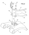
- Fig. 2 is an exploded perspective view of the steered angle detection mechanism 20.
- the steered angle detection mechanism 20 includes: a swivel case 22 provided to face the stem bracket 16 ( Fig. 1 ); an angle sensor 24 provided in a region 23 immediately over the swivel case 22; a mount frame 25 mounted on the swivel case 22 and having the swivel shaft 17 integrally incorporated therein; and a curved member 31 connected to a distal end portion 26 of the mount frame 25 by means of bolts 27.
- the angle sensor 24 includes a sensor body section 32 mounted on the swivel case 22, a pivot member 34 mounted on the sensor body section 32 for pivoting movement about a vertical pivot axis 33, and a contact 35 provided at a distal end portion of the pivot member 34.
- the contact 35 is held in contact with a curved outer peripheral surface 36 of the curved member 31.
- an operating angle of the angle sensor 24 only has to be about half of the above-mentioned maximum or full steered angle of the outboard engine body 19, and thus, the angle sensor 24 may be an inexpensive angle sensor.
- the angle sensor 24 may comprise, for example, a trim angle sensor which measures a tilt angle of a jet nozzle provided at the stem of a jet propulsion boat and whose operating angle need not be so great.
- a tilting shaft 37 extends through the stem bracket 16 connected to the boat body.
- the swivel case 22 is pivotably mounted on the tilting shaft 37.
- the swivel case 22 has a bearing 41, via which the swivel shaft 17 is horizontally pivotably mounted.
- the mount frame 25 having the swivel shaft 17 integrally incorporated therein is pivotable about the swivel shaft 17 as indicated by arrow (1).
- the contact 35 is normally urged in contact with the curved outer peripheral surface 36.
- the curved member 31 is normally held in sliding contact engagement with the contact 35.
- the contact 35 slides along the curved outer peripheral surface 36.
- the outboard engine unit 10 also includes a steering section 42 operable by the steerperson for pivoting the outboard engine body 19 ( Fig. 1 ) about the swivel shaft 17.
- the steering section 43 includes an arithmetic section 43 for calculating a steered angle of the outboard engine body 19 on the basis of detection information, indicative of an operating angle of the contact 35, output from the angle sensor 24, and a display section 44 for displaying the steered angle calculated by the arithmetic section 42 to allow the steerperson to visually check the steered angle.
- the arithmetic section 43 may calculate the steered angle on the basis of the detection information using, for example, a memory-stored table having stored therein steered angles in association with possible operating angles of the contact 35.
- the steering section 42 which is shown only conceptually as a rectangular block in the figure, is where a steering handle operable by the steerperson is provided.
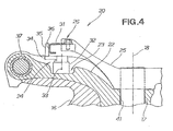
- Fig. 4 the swivel case 22 is provided in contact with an upper surface portion of the stem bracket 16, the angle sensor 24 is provided in the region 23 immediately over the swivel case 22, and the curved member 31 is provided to face the angle sensor 24.
- the contact 35 can always maintain its contact with the curved outer peripheral surface 36.
- the contact 35 angularly moves on the pivot member 34, i.e. varies in its operating angle, while sliding along the curved outer peripheral surface 36 in response to steering operation by the steerperson.
- a line passing centrally between opposed mounting surfaces 45 and 46 of the curved member 31 will hereinafter be referred to as "imaginary reference line 47", and the reference line 47 and the curved outer peripheral surface 36 intersect with each other at an intersection point 48.
- Fig. 5 further shows a left-side point 51 and a right-side point 52 of the curved outer peripheral surface 36 located to the left and right, respectively, of the reference line 47, and normal lines passing the points 48, 51 and 52 perpendicularly to the curved outer peripheral surface 36. These normal lines passing the points 48, 51 and 52 intersect with one another at an imaginary center point 53. Further, in Fig.
- distances from the imaginary center point 53 to the points 48, 51 and 52 are indicated by R0, R1 and R2, respectively, and these distances R0, R1 and R2 are set to establish a relationship of "R2 ⁇ R0 ⁇ R1"; namely, in the illustrated example of Fig. 5 , the distance R1 near the left end of the curved outer peripheral surface 36 is the greatest among the distances.
- the imaginary center point 53 is spaced from the imaginary reference line 47 by a distance L, and an arc having a radius R0 from the imaginary center point 53 is indicated at 54.
- the swivel shaft 17 ( Fig. 3 ) has a center 55 (corresponding to the central axis 18) that is located on the reference line 47, and a radius of curvature of the curved member 31 from the center 55 of the swivel shaft 17 varies continuously.
- the curved outer peripheral surface 36 is formed in a substantially arc shape having the imaginary center point 53 offset from the central axis 18 of the swivel shaft 17.
- the distances R1 and R2 and the length of the pivot member 34 are chosen so as to allow the operating angle of the contact 35 of the sensor 24 to be less than half of the steered angle.
- the curved member 31 has bearing or seating surfaces 56 and 57 so that the curved member 31 can be reliably mounted on the distal end portion 26 of the mount frame 25 ( Fig. 2 ).
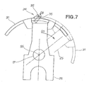
- the curved member 31 is normally held in sliding contact engagement with the contact 35.
- the mount frame 25 angularly moves (in a clockwise direction in the figure) to a position depicted by imaginary line as indicated by arrow (2), by which the contact 35 is angularly moved (in a counterclockwise direction in the figure) by the curved member 31, having the continuously varying radius of curvature, to a position depicted by imaginary line as indicated by arrow (3).
- the arithmetic section 43 calculates the steered angle on the basis of the detection information from the angle sensor 24 using, for example, the memory-stored table as noted above.
- the contact 35 can be kept at a relatively small operating angle even when the mount frame 25 has been moved a great distance and hence the steered angle has increased considerably.
- the outboard engine unit can achieve satisfactory performance even with the inexpensive angle sensor 24 in which the maximum operating angle of the contact 35 is not greater than half of the maximum steered angle.
- the center 55 of the swivel shaft 17 is on the central axis 18 ( Fig. 4 ) of the swivel shaft 17.
- the present invention is also applicable to outboard engines steerable through operation of a tiller handle. Namely, the basic principles of the present invention are appropriately applicable to any other types of steerable outboard engines.
- Outboard engine body (19) is mounted via a swivel shaft (17) to a stem bracket (16).
- Angle sensor (24), provided on the stem bracket, includes a contact (35) having a maximum operating angle set to be not greater than half of a maximum steered angle of the engine body, and it outputs detection information indicative of an operating angle of the contact (35).
- Curved member (31) is provided on the engine body (19) and normally held in engagement with the contact (35), and it has a continuously-varying radius of curvature from the central axis (18) of the swivel shaft (17), so that the contact (35) varies in operating angle while sliding along a curved outer peripheral surface (36) of the curved member in response to steering operation.
- a steered angle is determined on the basis of the detection information from the angle sensor.
Landscapes
- Chemical & Material Sciences (AREA)
- Engineering & Computer Science (AREA)
- Combustion & Propulsion (AREA)
- Mechanical Engineering (AREA)
- Ocean & Marine Engineering (AREA)
- Combined Controls Of Internal Combustion Engines (AREA)
- Measurement Of Length, Angles, Or The Like Using Electric Or Magnetic Means (AREA)
- Length Measuring Devices With Unspecified Measuring Means (AREA)
Abstract
Description
- The present invention relates to outboard engine units capable of detecting steered angles.
- Techniques for detecting a steered angle of an outboard engine by use of a rotational angle sensor have been known, one example of which is disclosed in Japanese Patent Application Laid-Open Publication No.
2004-230949 JP 2004-230949 A -
Fig. 8 hereof illustrates the technique disclosed inJP 2004-230949 A outboard engine unit 100, which is mounted to a hull orbody 101 of a boat via astem bracket 102, has anoutboard engine body 103 rotatably mounted to thestem bracket 102 via aswivel shaft 104. Theoutboard engine body 103 is steered about acentral axis 106 of theswivel shaft 104 by a steerperson moving atiller handle 105 horizontally leftward or rightward (i.e., toward or away from a person viewing the figure). A steered angle of theoutboard engine body 103 is detected via a pivotal angle sensor 107 provided on theswivel shaft 104. - The
outboard engine body 103 is sometimes steered through 50 degrees or more at the time of leftward or rightward steering. Thus, the pivotal angle sensor 107 is required to have a capability of detecting pivot angles of 100 degrees or more corresponding to a sum of such possible leftward and rightward steered angles. - However, the pivotal angle sensor 107 capable of detecting pivot angles of 100 degrees or more is expensive, increasing overall cost of the
outboard engine unit 100. Thus, there has been a need for an outboard engine unit which is provided with an inexpensive steered angle detection mechanism and yet can achieve satisfactory performance. - In view of the foregoing prior art problems, it is an object of the present invention to provide an improved outboard engine unit which can achieve satisfactory performance even with an inexpensive steered angle detection mechanism capable of reducing cost of the outboard engine unit.
- In order to accomplish the above-mentioned object, the present invention provides an improved outboard engine unit, which comprises: an outboard engine body mounted via a swivel shaft to a stem bracket fixedly connected to a body of a boat, the outboard engine body being horizontally pivotable relative to the stem bracket up to a predetermined maximum steered angle about the swivel shaft; an angle sensor provided on the stem bracket and including a contact having a maximum operating angle set to be not greater than half of the predetermined maximum steered angle, the angle sensor outputting detection information indicative of an operating angle of the contact; and a curved member provided on the outboard engine body and formed in a shape such that its radius of curvature from the center axis of the swivel shaft varies continuously, the curved member being normally held in sliding contact engagement with the contact in such a manner that the contact varies in its operating angle while sliding along a curved outer peripheral surface of the curved member in response to steering operation.
- In the outboard engine unit of the present invention, the angle sensor, of which the contact (member) has the maximum operating angle not greater than the maximum steerable of the outboard engine, is provided on the stem bracket. The curved member held in sliding engagement with the contact is provided on the outboard engine body, and the curved member has a shape such that its radius of curvature from the swivel shaft continuously varies. Generally, angle sensors, of which the contact has a small maximum operating angle, are inexpensive. Because the steered angle detection mechanism in the present invention includes the curved member and the angle sensor whose operating angle is not greater than half of the maximum steered angle of the outboard engine body, the present invention can reduce the cost of the steered angle detection mechanism and hence the overall cost of the outboard engine unit. In addition, because a proven trim angle sensor can be used as the angle sensor, of which the contact (member) has the maximum operating angle not greater than the maximum steered angle of the outboard engine body, the present invention can achieve an enhance reliability of the steered angle detection mechanism.
- Preferably, the outboard engine unit of the present invention further comprises a steering section for horizontally pivoting the outboard engine body about the swivel shaft, and the steering section includes an arithmetic section for calculating a steered angle of the outboard engine body on the basis of the detection information output from the angle sensor, and a display section for displaying the steered angle calculated by the arithmetic section. This arrangement allows a steerperson to visually check a steered angle of the outboard engine during travel and thus can achieve an enhanced operability.
- Preferably, the curved outer peripheral surface of the curved member is of a generally arc shape having an imaginary center point offset from the central axis of the swivel shaft.
- The following will describe embodiments of the present invention, but it should be appreciated that the present invention is not limited to the described embodiments and various modifications of the invention are possible without departing from the basic principles. The scope of the present invention is therefore to be determined solely by the appended claims.
- Certain preferred embodiments of the present invention will hereinafter be described in detail, by way of example only, with reference to the accompanying drawings, in which:
-
Fig. 1 is an overall side view of an embodiment of an outboard engine unit of the present invention; -
Fig. 2 is an exploded perspective view of a steered angle detection mechanism provided in the outboard engine unit of the present invention; -
Fig. 3 is a sectional view taken along the 3 - 3 line ofFig. 1 ; -
Fig. 4 is a sectional view taken along the 4 - 4 line ofFig. 3 ; -
Fig. 5 is a plan view of a curved member provided in the outboard engine unit of the present invention; -
Fig. 6 is a front view of the curved member provided in the outboard engine unit of the present invention; -
Fig. 7 is a view explanatory of behavior of the steered angle detection mechanism provided in the outboard engine unit of the present invention; and -
Fig. 8 is a view explanatory of behavior of a conventionally-known outboard engine unit. - Initial reference is made to
Fig. 1 which illustrate in side elevation an overall arrangement of an embodiment of an outboard engine unit according to the present invention. As shown, theoutboard engine unit 10 includes an outboard engine 11 provided in an upper section of theunit 10. The outboard engine 11 is a vertically placed engine with a cylinder and piton oriented horizontally and with a crankshaft and cam shaft oriented vertically. A direction in which a boat, having the outboard engine 11 mounted thereon travels forward, is a leftward direction in the figure. - The
outboard engine unit 10 also includes: anupper engine cover 12 that covers an upper portion of the outboard engine 11; alower engine cover 13 disposed under theupper engine cover 12 to cover a lower portion of the outboard engine 11; anextension case 14 disposed under thelower engine cover 13; and agear case 15 disposed under theextension case 14. - The
outboard engine 10 includes anoutboard engine body 19 mounted via a verticalswivel shaft 17 to astem bracket 16 that is in turn fixedly connected to a hull or body of the boat, and theengine body 19 is horizontally pivotable relative to thestem bracket 16 up to a predetermined maximum steered angle about a central axis (line) 18 of theswivel shaft 17. Theoutboard engine unit 10 also includes a steeredangle detection mechanism 20 provided in a front region of the portion covered with thelower engine cover 13. - Behind the
gear case 15 is disposed apropeller 21 rotatable by power produced by the outboard engine 11 to provide propelling power. Thepropeller 21 is switchable between forward rotation and reverse rotation via a pair of dog clutches, to thereby provide forward or rearward propelling power. - The
upper engine cover 12 is mounted to thelower engine cover 13 by means of arear fastener 28 with a hook engaged with a front inner surface of thelower engine cover 13. -
Fig. 2 is an exploded perspective view of the steeredangle detection mechanism 20. As shown, the steeredangle detection mechanism 20 includes: aswivel case 22 provided to face the stem bracket 16 (Fig. 1 ); anangle sensor 24 provided in aregion 23 immediately over theswivel case 22; amount frame 25 mounted on theswivel case 22 and having theswivel shaft 17 integrally incorporated therein; and acurved member 31 connected to adistal end portion 26 of themount frame 25 by means ofbolts 27. - The
angle sensor 24 includes asensor body section 32 mounted on theswivel case 22, apivot member 34 mounted on thesensor body section 32 for pivoting movement about avertical pivot axis 33, and acontact 35 provided at a distal end portion of thepivot member 34. Thecontact 35 is held in contact with a curved outerperipheral surface 36 of thecurved member 31. - In the instant embodiment, an operating angle of the
angle sensor 24 only has to be about half of the above-mentioned maximum or full steered angle of theoutboard engine body 19, and thus, theangle sensor 24 may be an inexpensive angle sensor. Theangle sensor 24 may comprise, for example, a trim angle sensor which measures a tilt angle of a jet nozzle provided at the stem of a jet propulsion boat and whose operating angle need not be so great. - The following describe primary relevant sections of the embodiment of the outboard engine unit, with reference to
Fig. 3 that is a sectional plan view of the outboard engine unit. As shown inFig. 3 , a tiltingshaft 37 extends through thestem bracket 16 connected to the boat body. Theswivel case 22 is pivotably mounted on the tiltingshaft 37. Theswivel case 22 has abearing 41, via which theswivel shaft 17 is horizontally pivotably mounted. Themount frame 25 having theswivel shaft 17 integrally incorporated therein is pivotable about theswivel shaft 17 as indicated by arrow (1). - The
contact 35 is normally urged in contact with the curved outerperipheral surface 36. In other words, thecurved member 31 is normally held in sliding contact engagement with thecontact 35. As thecurved member 31 horizontally pivots together with themount frame 25 in response to steering operation performed by a steerperson, thecontact 35 slides along the curved outerperipheral surface 36. - The
outboard engine unit 10 also includes asteering section 42 operable by the steerperson for pivoting the outboard engine body 19 (Fig. 1 ) about theswivel shaft 17. Thesteering section 43 includes anarithmetic section 43 for calculating a steered angle of theoutboard engine body 19 on the basis of detection information, indicative of an operating angle of thecontact 35, output from theangle sensor 24, and adisplay section 44 for displaying the steered angle calculated by thearithmetic section 42 to allow the steerperson to visually check the steered angle. Thearithmetic section 43 may calculate the steered angle on the basis of the detection information using, for example, a memory-stored table having stored therein steered angles in association with possible operating angles of thecontact 35. Thesteering section 42, which is shown only conceptually as a rectangular block in the figure, is where a steering handle operable by the steerperson is provided. - The following describe the primary sections of the outboard engine unit of the present invention, with reference to a sectional side view of
Fig. 4 . As shown inFig. 4 , theswivel case 22 is provided in contact with an upper surface portion of thestem bracket 16, theangle sensor 24 is provided in theregion 23 immediately over theswivel case 22, and thecurved member 31 is provided to face theangle sensor 24. - Although the
curved member 31 is pivotable about thecentral axis 18 of theswivel shaft 17 without contacting thesensor body section 32, thecontact 35 can always maintain its contact with the curved outerperipheral surface 36. Thus, thecontact 35 angularly moves on thepivot member 34, i.e. varies in its operating angle, while sliding along the curved outerperipheral surface 36 in response to steering operation by the steerperson. - The following describe in detail the shape of the
curved member 31. In a plan view ofFig. 5 , a line passing centrally between opposedmounting surfaces curved member 31 will hereinafter be referred to as "imaginary reference line 47", and thereference line 47 and the curved outerperipheral surface 36 intersect with each other at anintersection point 48.Fig. 5 further shows a left-side point 51 and a right-side point 52 of the curved outerperipheral surface 36 located to the left and right, respectively, of thereference line 47, and normal lines passing thepoints peripheral surface 36. These normal lines passing thepoints imaginary center point 53. Further, inFig. 5 , distances from theimaginary center point 53 to thepoints Fig. 5 , the distance R1 near the left end of the curved outerperipheral surface 36 is the greatest among the distances. Furthermore, theimaginary center point 53 is spaced from theimaginary reference line 47 by a distance L, and an arc having a radius R0 from theimaginary center point 53 is indicated at 54. - Further, in
Fig. 5 , the swivel shaft 17 (Fig. 3 ) has a center 55 (corresponding to the central axis 18) that is located on thereference line 47, and a radius of curvature of thecurved member 31 from thecenter 55 of theswivel shaft 17 varies continuously. Namely, the curved outerperipheral surface 36 is formed in a substantially arc shape having theimaginary center point 53 offset from thecentral axis 18 of theswivel shaft 17. In the instant embodiment, the distances R1 and R2 and the length of thepivot member 34 are chosen so as to allow the operating angle of thecontact 35 of thesensor 24 to be less than half of the steered angle. - As shown in
Fig. 6 , thecurved member 31 has bearing or seating surfaces 56 and 57 so that thecurved member 31 can be reliably mounted on thedistal end portion 26 of the mount frame 25 (Fig. 2 ). - The following describe behavior of the steered
angle detection mechanism 20 constructed in the aforementioned manner. As shown inFig. 7 , thecurved member 31 is normally held in sliding contact engagement with thecontact 35. As the outboard engine body 19 (Fig. 1 ) is steered via thesteering section 42, themount frame 25 angularly moves (in a clockwise direction in the figure) to a position depicted by imaginary line as indicated by arrow (2), by which thecontact 35 is angularly moved (in a counterclockwise direction in the figure) by thecurved member 31, having the continuously varying radius of curvature, to a position depicted by imaginary line as indicated by arrow (3). In this way, a steered angle of theoutboard engine body 19 can be detected via theangle sensor 24. More specifically, thearithmetic section 43 calculates the steered angle on the basis of the detection information from theangle sensor 24 using, for example, the memory-stored table as noted above. - In the embodiment of the outboard engine body of the present invention, as described above, the
contact 35 can be kept at a relatively small operating angle even when themount frame 25 has been moved a great distance and hence the steered angle has increased considerably. As a result, the outboard engine unit can achieve satisfactory performance even with theinexpensive angle sensor 24 in which the maximum operating angle of thecontact 35 is not greater than half of the maximum steered angle. Note that thecenter 55 of theswivel shaft 17 is on the central axis 18 (Fig. 4 ) of theswivel shaft 17. - Whereas the preferred embodiment of the present invention has been described above as applied to the outboard engine steerable through operation of the steering handle, the present invention is also applicable to outboard engines steerable through operation of a tiller handle. Namely, the basic principles of the present invention are appropriately applicable to any other types of steerable outboard engines.
- The present invention is well suited for application to outboard engines requiring detection of steered angles.
Outboard engine body (19) is mounted via a swivel shaft (17) to a stem bracket (16). Angle sensor (24), provided on the stem bracket, includes a contact (35) having a maximum operating angle set to be not greater than half of a maximum steered angle of the engine body, and it outputs detection information indicative of an operating angle of the contact (35). Curved member (31) is provided on the engine body (19) and normally held in engagement with the contact (35), and it has a continuously-varying radius of curvature from the central axis (18) of the swivel shaft (17), so that the contact (35) varies in operating angle while sliding along a curved outer peripheral surface (36) of the curved member in response to steering operation. Thus, a steered angle is determined on the basis of the detection information from the angle sensor.
Claims (3)
- An outboard engine unit (10) comprising:an outboard engine body (19) mounted via a swivel shaft (17) to a stem bracket (16) fixedly connected to a body of a boat, the outboard engine body being horizontally pivotable relative to the stem bracket up to a predetermined maximum steered angle about the swivel shaft;an angle sensor (24) provided on the stem bracket (16) and including a contact (35) having a maximum operating angle set to be not greater than half of the predetermined maximum steered angle, the angle sensor (24) outputting detection information indicative of an operating angle of the contact (35); anda curved member (31) provided on the outboard engine body (19) and formed in a shape such that a radius of curvature thereof from a center axis (18) of the swivel shaft (17) varies continuously, the curved member (31) being normally held in sliding contact engagement with the contact (35) in such a manner that the contact (35) varies in operating angle thereof while sliding along a curved outer peripheral surface (36) of the curved member (31) in response to steering operation.
- The outboard engine unit of claim 1, further comprising a steering section (42) for horizontally pivoting the outboard engine body (19) about the swivel shaft (17), wherein the steering section (42) includes an arithmetic section (43) for calculating a steered angle of the outboard engine body on the basis of the detection information output by the angle sensor (24), and a display section (44) for displaying the steered angle calculated by the arithmetic section (43).
- The outboard engine unit of claim 1, wherein the curved outer peripheral surface (36) of the curved member (31) is of a generally arc shape having an imaginary center point offset from the central axis (18) of the swivel shaft (17).
Applications Claiming Priority (1)
| Application Number | Priority Date | Filing Date | Title |
|---|---|---|---|
| JP2009109048A JP5186433B2 (en) | 2009-04-28 | 2009-04-28 | Outboard motor |
Publications (2)
| Publication Number | Publication Date |
|---|---|
| EP2246251A1 true EP2246251A1 (en) | 2010-11-03 |
| EP2246251B1 EP2246251B1 (en) | 2011-08-03 |
Family
ID=42235241
Family Applications (1)
| Application Number | Title | Priority Date | Filing Date |
|---|---|---|---|
| EP10161038A Active EP2246251B1 (en) | 2009-04-28 | 2010-04-26 | Outboard engine unit |
Country Status (4)
| Country | Link |
|---|---|
| US (1) | US8142243B2 (en) |
| EP (1) | EP2246251B1 (en) |
| JP (1) | JP5186433B2 (en) |
| CA (1) | CA2701264C (en) |
Families Citing this family (2)
| Publication number | Priority date | Publication date | Assignee | Title |
|---|---|---|---|---|
| JP7226141B2 (en) * | 2019-06-28 | 2023-02-21 | スズキ株式会社 | Outboard motor |
| USD958192S1 (en) | 2019-10-25 | 2022-07-19 | Brunswick Corporation | Tie bar apparatus for an outboard motor |
Citations (5)
| Publication number | Priority date | Publication date | Assignee | Title |
|---|---|---|---|---|
| US4759732A (en) * | 1986-04-01 | 1988-07-26 | Sanshin Kogyo Kabushiki Kaisha | Trim tab actuator for marine propulsion device |
| JP2004230949A (en) | 2003-01-28 | 2004-08-19 | Honda Motor Co Ltd | Outboard motor |
| US20050215131A1 (en) * | 2004-03-26 | 2005-09-29 | Takahiro Oguma | Steering system of outboard motor |
| US20060110990A1 (en) * | 2004-11-25 | 2006-05-25 | Honda Motor Co., Ltd. | Outboard motor steering control system |
| US20070218785A1 (en) * | 2006-03-14 | 2007-09-20 | Yamaha Marine Kabushiki Kaisha | Watercraft propulsion apparatus and watercraft |
Family Cites Families (6)
| Publication number | Priority date | Publication date | Assignee | Title |
|---|---|---|---|---|
| US2700358A (en) * | 1954-09-07 | 1955-01-25 | Grover D Johnson | Steering assembly for outboard motorboats |
| US3623446A (en) * | 1969-05-19 | 1971-11-30 | Outboard Marine Corp | Swivel bracket lock no back steering |
| US5029547A (en) * | 1988-10-20 | 1991-07-09 | Novey Richard T | Remote steering control for outboard powerheads |
| JP2006256350A (en) * | 2005-03-15 | 2006-09-28 | Honda Motor Co Ltd | Steering device of outboard motor |
| JP4685508B2 (en) * | 2005-05-20 | 2011-05-18 | 本田技研工業株式会社 | Outboard motor steering system |
| JP4895637B2 (en) * | 2006-02-20 | 2012-03-14 | 本田技研工業株式会社 | Outboard motor steering system |
-
2009
- 2009-04-28 JP JP2009109048A patent/JP5186433B2/en active Active
-
2010
- 2010-04-21 CA CA2701264A patent/CA2701264C/en not_active Expired - Fee Related
- 2010-04-26 EP EP10161038A patent/EP2246251B1/en active Active
- 2010-04-26 US US12/767,240 patent/US8142243B2/en active Active
Patent Citations (5)
| Publication number | Priority date | Publication date | Assignee | Title |
|---|---|---|---|---|
| US4759732A (en) * | 1986-04-01 | 1988-07-26 | Sanshin Kogyo Kabushiki Kaisha | Trim tab actuator for marine propulsion device |
| JP2004230949A (en) | 2003-01-28 | 2004-08-19 | Honda Motor Co Ltd | Outboard motor |
| US20050215131A1 (en) * | 2004-03-26 | 2005-09-29 | Takahiro Oguma | Steering system of outboard motor |
| US20060110990A1 (en) * | 2004-11-25 | 2006-05-25 | Honda Motor Co., Ltd. | Outboard motor steering control system |
| US20070218785A1 (en) * | 2006-03-14 | 2007-09-20 | Yamaha Marine Kabushiki Kaisha | Watercraft propulsion apparatus and watercraft |
Also Published As
| Publication number | Publication date |
|---|---|
| CA2701264C (en) | 2012-02-21 |
| JP5186433B2 (en) | 2013-04-17 |
| EP2246251B1 (en) | 2011-08-03 |
| US20100273368A1 (en) | 2010-10-28 |
| US8142243B2 (en) | 2012-03-27 |
| JP2010254214A (en) | 2010-11-11 |
| CA2701264A1 (en) | 2010-10-28 |
Similar Documents
| Publication | Publication Date | Title |
|---|---|---|
| US8170734B2 (en) | Marine vessel maneuvering supporting apparatus and marine vessel including the same | |
| US7267587B2 (en) | Steering system of outboard motor | |
| US10046842B2 (en) | Outboard motor mounting structure and outboard motor vessel provided therewith | |
| US9045212B2 (en) | Suspension device for outboard motor and vessel propulsion apparatus | |
| US12134447B2 (en) | Watercraft | |
| EP2246251B1 (en) | Outboard engine unit | |
| JP6646477B2 (en) | Small ship contact avoidance device | |
| US7452250B2 (en) | Outboard motor steering control system | |
| EP3718875B1 (en) | System for maneuvering boats | |
| JP4300055B2 (en) | Ship steering system with swivel bracket hydraulic cylinder | |
| JPS6271799A (en) | Steering gear for ship | |
| US11851152B2 (en) | Outboard motor | |
| US20080102718A1 (en) | Shift mechanism of outboard motor | |
| JP2013014159A (en) | Ship rudder fixing device and ship maneuvering method when ship rudder is fixed | |
| US7806068B2 (en) | Rudder for marine vehicles | |
| JP7226141B2 (en) | Outboard motor | |
| US20020193021A1 (en) | Tilt support mechanism for outboard motor | |
| JP2019001209A (en) | Steering handle of outboard engine | |
| JP4393921B2 (en) | Outboard motor trim sender mechanism | |
| JP4279636B2 (en) | Outboard motor | |
| JP4571533B2 (en) | Electric power steering device for marine propulsion equipment | |
| JP4279635B2 (en) | Outboard motor | |
| JPH0523438Y2 (en) | ||
| JP4884193B2 (en) | Ship | |
| JP2004189094A (en) | Outboard motor |
Legal Events
| Date | Code | Title | Description |
|---|---|---|---|
| PUAI | Public reference made under article 153(3) epc to a published international application that has entered the european phase |
Free format text: ORIGINAL CODE: 0009012 |
|
| 17P | Request for examination filed |
Effective date: 20100426 |
|
| AK | Designated contracting states |
Kind code of ref document: A1 Designated state(s): AT BE BG CH CY CZ DE DK EE ES FI FR GB GR HR HU IE IS IT LI LT LU LV MC MK MT NL NO PL PT RO SE SI SK SM TR |
|
| AX | Request for extension of the european patent |
Extension state: AL BA ME RS |
|
| GRAP | Despatch of communication of intention to grant a patent |
Free format text: ORIGINAL CODE: EPIDOSNIGR1 |
|
| RIC1 | Information provided on ipc code assigned before grant |
Ipc: B63H 20/12 20060101AFI20101210BHEP Ipc: B63H 25/02 20060101ALI20101210BHEP |
|
| GRAS | Grant fee paid |
Free format text: ORIGINAL CODE: EPIDOSNIGR3 |
|
| RBV | Designated contracting states (corrected) |
Designated state(s): DE FR GB |
|
| RIN1 | Information on inventor provided before grant (corrected) |
Inventor name: SAKATA, SHIGEKAZU Inventor name: OHTOMO, YOSHIO Inventor name: SHIMIZU, NORIKAZU Inventor name: MIZUGUCHI, HIROSHI |
|
| GRAA | (expected) grant |
Free format text: ORIGINAL CODE: 0009210 |
|
| AK | Designated contracting states |
Kind code of ref document: B1 Designated state(s): DE FR GB |
|
| REG | Reference to a national code |
Ref country code: GB Ref legal event code: FG4D |
|
| REG | Reference to a national code |
Ref country code: DE Ref legal event code: R096 Ref document number: 602010000128 Country of ref document: DE Effective date: 20111013 |
|
| PLBE | No opposition filed within time limit |
Free format text: ORIGINAL CODE: 0009261 |
|
| STAA | Information on the status of an ep patent application or granted ep patent |
Free format text: STATUS: NO OPPOSITION FILED WITHIN TIME LIMIT |
|
| 26N | No opposition filed |
Effective date: 20120504 |
|
| REG | Reference to a national code |
Ref country code: DE Ref legal event code: R097 Ref document number: 602010000128 Country of ref document: DE Effective date: 20120504 |
|
| REG | Reference to a national code |
Ref country code: FR Ref legal event code: PLFP Year of fee payment: 7 |
|
| REG | Reference to a national code |
Ref country code: FR Ref legal event code: PLFP Year of fee payment: 8 |
|
| REG | Reference to a national code |
Ref country code: FR Ref legal event code: PLFP Year of fee payment: 9 |
|
| PGFP | Annual fee paid to national office [announced via postgrant information from national office to epo] |
Ref country code: GB Payment date: 20190424 Year of fee payment: 10 |
|
| REG | Reference to a national code |
Ref country code: DE Ref legal event code: R084 Ref document number: 602010000128 Country of ref document: DE |
|
| REG | Reference to a national code |
Ref country code: GB Ref legal event code: 746 Effective date: 20191219 |
|
| PGFP | Annual fee paid to national office [announced via postgrant information from national office to epo] |
Ref country code: FR Payment date: 20200312 Year of fee payment: 11 |
|
| GBPC | Gb: european patent ceased through non-payment of renewal fee |
Effective date: 20200426 |
|
| PG25 | Lapsed in a contracting state [announced via postgrant information from national office to epo] |
Ref country code: GB Free format text: LAPSE BECAUSE OF NON-PAYMENT OF DUE FEES Effective date: 20200426 |
|
| PG25 | Lapsed in a contracting state [announced via postgrant information from national office to epo] |
Ref country code: FR Free format text: LAPSE BECAUSE OF NON-PAYMENT OF DUE FEES Effective date: 20210430 |
|
| PGFP | Annual fee paid to national office [announced via postgrant information from national office to epo] |
Ref country code: DE Payment date: 20250319 Year of fee payment: 16 |