EP2246231A1 - Parking assistant system - Google Patents
Parking assistant system Download PDFInfo
- Publication number
- EP2246231A1 EP2246231A1 EP09425168A EP09425168A EP2246231A1 EP 2246231 A1 EP2246231 A1 EP 2246231A1 EP 09425168 A EP09425168 A EP 09425168A EP 09425168 A EP09425168 A EP 09425168A EP 2246231 A1 EP2246231 A1 EP 2246231A1
- Authority
- EP
- European Patent Office
- Prior art keywords
- vehicle
- manoeuvre
- line
- parking
- driver
- Prior art date
- Legal status (The legal status is an assumption and is not a legal conclusion. Google has not performed a legal analysis and makes no representation as to the accuracy of the status listed.)
- Granted
Links
Images


Classifications
-
- B—PERFORMING OPERATIONS; TRANSPORTING
- B60—VEHICLES IN GENERAL
- B60W—CONJOINT CONTROL OF VEHICLE SUB-UNITS OF DIFFERENT TYPE OR DIFFERENT FUNCTION; CONTROL SYSTEMS SPECIALLY ADAPTED FOR HYBRID VEHICLES; ROAD VEHICLE DRIVE CONTROL SYSTEMS FOR PURPOSES NOT RELATED TO THE CONTROL OF A PARTICULAR SUB-UNIT
- B60W30/00—Purposes of road vehicle drive control systems not related to the control of a particular sub-unit, e.g. of systems using conjoint control of vehicle sub-units
- B60W30/06—Automatic manoeuvring for parking
-
- B—PERFORMING OPERATIONS; TRANSPORTING
- B62—LAND VEHICLES FOR TRAVELLING OTHERWISE THAN ON RAILS
- B62D—MOTOR VEHICLES; TRAILERS
- B62D15/00—Steering not otherwise provided for
- B62D15/02—Steering position indicators ; Steering position determination; Steering aids
- B62D15/027—Parking aids, e.g. instruction means
- B62D15/0275—Parking aids, e.g. instruction means by overlaying a vehicle path based on present steering angle over an image without processing that image
-
- B—PERFORMING OPERATIONS; TRANSPORTING
- B62—LAND VEHICLES FOR TRAVELLING OTHERWISE THAN ON RAILS
- B62D—MOTOR VEHICLES; TRAILERS
- B62D15/00—Steering not otherwise provided for
- B62D15/02—Steering position indicators ; Steering position determination; Steering aids
- B62D15/027—Parking aids, e.g. instruction means
- B62D15/028—Guided parking by providing commands to the driver, e.g. acoustically or optically
Definitions
- the subject of the present invention is a parking assistant system for assisting the driver in a reverse manoeuvre to park the vehicle at the roadside parallel to the direction of the road in a parking space between a first obstacle and a second obstacle, which define, respectively, the front limit and the rear limit of said space with respect to the body of the vehicle.
- the invention regards a system of the type comprising:
- the European patent application No. EP1493632A1 describes a parking assistant system of the type indicated above.
- a line of assistance is provided, which enables the driver to identify a set of positions starting from which the parking manoeuvre can be correctly made according to a pre-set mode, without coming into collision with the obstacles that delimit the parking space.
- Said so-called correct positions, which are defined by the line of assistance, are at a relatively long distance from the internal longitudinal edge of the parking space so that the driver is obliged to perform the parking manoeuvre in three distinct steps, schematically represented by the dashed lines 111, 112 and 113 of Figure 1 .
- the first step 111 envisages backing up with a first steering angle
- the second step 112 envisages backing up with a zero steering angle
- the third and last step 113 envisages backing up with a second steering angle, of opposite sign with respect to the first.
- a type of manoeuvre of said sort is somewhat laborious and complex so that this system in the eyes of the user proves to be far from intuitive.
- the driver since said system leaves the choice of one out of all the so-called correct positions defined by the line of assistance to the driver's discretion, the driver is more induced to error in so far as, according to the start-of-manoeuvre position, he will have to carry out said manoeuvre in a different way in order to be able to bring the vehicle into the same final position.
- he will be forced to follow a rectilinear stretch in reverse, corresponding to the stretch 112 of Figure 1 , which is more or less long, according to the starting distance of the vehicle from the internal edge of the parking slot.
- the subject of the present invention is a parking assistant system that will overcome the drawbacks described above, and that in particular will be simple and intuitive.
- the subject of the present invention is a parking assistant system for assisting the driver in a reverse manoeuvre to park the vehicle at the roadside parallel to the direction of the road in a parking space between a first obstacle and a second obstacle, which define, respectively, the front limit and the rear limit of said space with respect to the body of the vehicle, the system comprising:
- the first line of assistance identifies, in a pre-set position of the image displayed, an ideal parking area of predetermined longitudinal and transverse dimensions, such that the body of the vehicle during the aforesaid manoeuvre intersects said ideal parking area only on its outer longitudinal side so that the driver is able to detect that he has reached said correct longitudinal and transverse start-of-manoeuvre position, when said first and second obstacles, as displayed, are set in a longitudinal direction outside the parking area and comprised in the transverse dimension of the parking area.
- the aforesaid line of assistance comprises a first line shaped like an L set upside down so as to define a limit to the external distal corner portion of the first obstacle, and a second line shaped like an L set upside down, which defines the internal distal corner of said ideal parking area, said second line shaped like an L set upside down together with the horizontal stretch of said first line defining said ideal parking area.
- the system of assistance envisages a reference whereby the driver is able to identify immediately the correct position from which to start the parking manoeuvre.
- Said position is defined in a longitudinal and transverse direction so that the driver will no longer be put in the condition of having to choose from among a plurality of positions, and above all he may follow the manoeuvre always in the same way, with the certainty that upon completion of the manoeuvre the vehicle will be always at the same distance from the internal longitudinal edge of the parking space.
- the parking assistant system moreover enables the driver to follow in an assisted way a parking manoeuvre in just two steps (as schematically illustrated with the lines 114 and 115 in Figure 2 ); said simplicity of execution enables the driver to get acquainted right from the start with the use of the system.
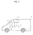
- FIG. 3 represents an example of block diagram of the parking assistant system according to the present invention.
- Said system comprises a video camera 2 for filming the scene to the rear of the vehicle.
- a control unit 3 is configured for displaying the image filmed by the video camera on a display 4, installed inside the vehicle within the field of vision of the driver.
- the control unit 3 is likewise configured for superimposing on the scene appearing on the display 4, lines of assistance that it has stored or calculated in real time, whenever it detects the condition of engagement of the reverse via a sensor 5.
- the system further comprises a sensor 6 designed to detect the steering angle of the vehicle; on the basis of said information, as will be seen in what follows, the control unit manages the lines of assistance.
- the lines of assistance of the system according to the present invention identify the ideal parking area, thanks to which the driver has a reference on the correct position, in a longitudinal and transverse direction, to be assumed in order to start the manoeuvre, and at the same time verifies that the free space is sufficiently large to park the vehicle.
- Figures 13 to 15 represent a geometrical scheme useful for identifying the dimensions of said ideal area and the pre-defined position of this on the display 4.
- Figure 13 represents, in a cartesian system X,Y, the body of the vehicle set in a position K corresponding to the end-of-parking position, in which the body of the vehicle is located at a pre-set distance Dm from the longitudinal edge r of the parking space.
- the distance Dm basically represents the distance from the edge r where the vehicle body is to be positioned, in the end-of-manoeuvre position K.
- An obstacle A is set with its external distal corner in the point of co-ordinates Obs_x and Obs_y + Bk.
- the transverse distance between the vehicle body and the obstacle A is equal to the pre-set distance t.
- the parking manoeuvre pre-established so that the vehicle body will move from position H to position K comprises a first manoeuvre in which, as illustrated in Figure 2 , the vehicle backs up from position H, with a first steering angle, until it reaches an intermediate position G, and a second manoeuvre in which the vehicle backs up starting from position G with a second steering angle of opposite sign with respect to the first, until it reaches the aforesaid position K.
- the unknown parameter that is to be found is the longitudinal dimension "park slot", indicated in Figure 13 , necessary in order for the body of the vehicle, starting from position H, to be able to follow the parking manoeuvre described above without coming into collision with the obstacle A.
- the steering angle of the second manoeuvre is pre-set at the maximum value that can be performed by the vehicle in order to limit the space necessary for parking as much as possible. Once the steering angle is known, it is possible to obtain the radius of curvature of the path that the point C of the vehicle, corresponding to the central point of the rear axle, will follow with said steering angle, via Eq. 1 given below.
- R_curvatura P ⁇ cot ⁇ i + cot ⁇ e 2 where ⁇ i and ⁇ e are the angles of the inner wheel and the outer wheel with respect to the curvature, and P is the wheel base of the vehicle.
- the steering-angle/wheel-angle relation is given by the manufacturer of the motor vehicle.
- Figure 13 represents the radius R2 obtained from Eq. 1.
- the circular path defined by the point C of the body of the vehicle terminates substantially tangential to an axis parallel to the axis y so that the radius R2 must necessarily extend orthogonal to the axis Y, starting from the point C of the body of the vehicle in position K.
- the centre of curvature H2 is identified. At this point, once H2 has been identified, it is possible to trace the circular paths centred in H2 followed by the corners O1, O2 and O3 of the body of the vehicle during the second manoeuvre.
- Dist _min D m - R 2 + C 2 cos tg - 1 ⁇ B k R 2 + C 2 - R 2 where C is the width of the vehicle body and Bk is the distance between the rear axle and the back of the vehicle.
- Said circumference has a radius RM, illustrated in Figure 13 .
- R1 is represented in Figure 13 and is an unknown of the system.
- the body of the vehicle In order to pass from the start-of-manoeuvre position H to the intermediate position G, the body of the vehicle must perform the first manoeuvre with a steering angle of opposite sign with respect to the steering angle used for the second manoeuvre. However, in order for the motor vehicle to be, at the end of the second manoeuvre, parallel to the wall, as shown in Figure 13 , the angle ⁇ that is defined by the path of point C in the second manoeuvre must be equal to the angle ⁇ subtended by the path of point C in the first manoeuvre.
- the dimension Park_Slot min obtained must be such that the body of the vehicle during the first manoeuvre will not collide with the obstacle A.
- a minimum radius of curvature is calculated as radius of the circular path that the body of the vehicle traverses during the first manoeuvre, starting from the position H, passing through the point P2 of co-ordinates (Obs_x + ⁇ x ; Obs_y + Bk), as illustrated in Figure 15 .
- the equation of the minimum radius is given below.
- R 1 , min C 2 2 - ⁇ x - t - C 2 2 - B k + Obs_y + ⁇ y 2 2 ⁇ C 2 + ⁇ x - t - C 2
- radius of curvature R1 is smaller than the minimum radius of curvature, it means that the dimension "park slot" of the ideal area that has been obtained is not sufficiently large for the body of the vehicle to move from position H to position K without colliding with the obstacle A. In this case, it will be necessary to modify one or more of the pre-set parameters Obs_x, t, Obs_y and reiterate the procedure described above until a radius R1 greater than the minimum radius calculated as indicated above is identified.
- the dimension "park slot” and the dimension Obs_x define the ideal parking area in a longitudinal and transverse direction. Since, as has been seen above, to obtain the "park slot” dimension there passage of the vehicle body through point P1 has been imposed, said point being located on the outer longitudinal side of the ideal area, at a distance ⁇ y from the vertex of the latter of co-ordinates Obs_x, Obs_y + Bk, the dimensions of the ideal area are such that the body of the vehicle, executing the manoeuvre in the way that has been determined above, intersects the ideal parking area only on its outer longitudinal side.
- the relative position of the rear edge of the body of the vehicle with respect to said ideal area is determined by the pre-set values t and Obs_y, which correspond, respectively, to the transverse distance and to the longitudinal distance between said rear edge and the distal outer corner of the obstacle A.
- the ideal area necessary for the parking manoeuvre and the correct position that the back of the vehicle must assume with respect to it for starting said manoeuvre are identified.
- said ideal area is identified by the lines of assistance, in a position that, with respect to the rear of the body of the vehicle, as displayed by the video camera, is defined so as to correspond to the aforesaid correct position.
- the ideal parking area thus defined on the display has the function of providing the driver with an indication both on the correct start-of-manoeuvre position and on the free space that is necessary in order to be able to park the vehicle.
- Figures 4-12 illustrate operation of the system in a scenario in which the vehicle is to be parked parallel to the left edge r, with respect to the direction of advance along the road, between two obstacles A and B.
- FIGS 4 and 5A illustrate an example of construction of the lines of assistance supplied by the system according to the present invention.
- the control unit 3 superimposes a black strip 11, at the bottom of the display in such a way as to cover the part of image corresponding to the back of the vehicle and to the area immediately close to it, these being, as a result of the optics of the video camera, displayed with distortions such that might lead to an incorrect perception of the scene by the driver.
- the line 12 has the shape of an L set upside down that defines an outer limit, with respect to the longitudinal edge r of the parking space, within which the obstacle A must be located so that the vehicle will not collide with it during the parking manoeuvre.
- the line 13 has the shape of an L set upside down, but in a way specular with respect to the line 12.
- the longitudinal stretch 13' of the line 13 supplies a reference for the driver on the transverse start-of-manoeuvre position that the vehicle must assume, with respect to the longitudinal edge of the parking space, so that at the end of the parking manoeuvre it will come to be at the pre-set distance Dm from said edge. Any possible obstacles that define the internal longitudinal edge of the parking space must find themselves beyond said line, outside the ideal area.
- the transverse stretch 13" of the line 13 defines, together with the horizontal stretch 12" of the line 12, the longitudinal dimension of the ideal parking area. Likewise, on account of what has been said above, the distance between the longitudinal stretches 12' and 13' of the lines 12 and 13 define the transverse dimension of the ideal parking area.
- lines 14 and 15 represent the lines of assistance, equivalent to the lines 12 and 13, for a parallel parking space on the right-hand side of the road.
- lines 16 Shown in Figures 4 and 5A are also lines 16 that represent so-called dynamic lines of assistance, which define the transverse area that the body of the vehicle comes to traverse, in a reverse manoeuvre at the current steering angle, which is detected by the sensor 6 illustrated in Figure 3 .
- the vehicle in the condition associated to said figures, is at a zero steering angle.
- the lines of assistance 12, 13, 14 and 15 described above are mobile with the vehicle with respect to the scene shown on the display and appear as static on the aforesaid display.
- control unit 3 can be configured for superimposing on the scene appearing on the display 4 all the lines of assistance described above, whether static or dynamic, whenever it detects the condition of engagement of the reverse via the sensor 5.
- a preferred embodiment of the invention envisages, however, the display of said lines of assistance also when the vehicle is travelling forwards so that, also when proceeding forwards, the driver will be equally allowed to align the vehicle correctly for the scenario of the subsequent step in reverse.
- Figure 4 illustrates a rear scene 10 corresponding to a position of the vehicle that is still far from the correct position for starting the parking manoeuvre.
- the driver will have to bring the vehicle into a position such that the lines of assistance 12 and 13, as displayed, set themselves with respect to the obstacles A and B in the way illustrated in Figure 5A .
- the obstacles A and B must come to be longitudinally outside the space comprised between the horizontal stretches of the lines 12 and 13, and comprised in the transverse dimension of the space between the longitudinal stretches of the lines 12 and 13 themselves.
- the ideal parking area 20, identified by the lines 12 and 13 must be set between the obstacles A and B and substantially aligned to the latter.
- the stretch 13' must be set substantially coincident with the edge r, or alternatively, in the case where the obstacle A is located at a sufficient distance from the edge r, the stretch 12 must be set substantially coinciding with the edge of the obstacle A that is closest to the vehicle, as shown in Figure 5B .
- the lines of assistance 12, 13, 14 and 15 disappear from the display in so far as, according to the logic of the system, the vehicle is by now already set in the correct position for starting the parking manoeuvre and the driver has already been able to verify that the free space between the obstacles A and B is sufficient for parking.
- the driver can thus start to back up the vehicle keeping the steering angle constant, at the pre-set value, until the line 17 comes to be superimposed on the longitudinal edge r, as represented in Figure 8 .
- the vehicle is in the intermediate position illustrated in Figure 9 , where the driver must stop the vehicle and turn the steering wheel until the pre-set value of steering angle for carrying out the second manoeuvre is reached.
- said pre-set angle corresponds to the maximum steering angle of the vehicle.
- Figure 10 illustrates what appears on the display when, in the position of the vehicle of Figure 9 , the driver has turned the steering wheel as far as the pre-set steering angle for the second manoeuvre.
- the lines 16 provide a visual confirmation for the driver of the way being free for the second manoeuvre and of the fact that at the end of said manoeuvre the vehicle will be in the parking space, substantially aligned to the longitudinal edge r.
- Figure 11 illustrates the scene appearing on the display at the end of the parking manoeuvre, when the vehicle is in the position illustrated in Figure 12 , at the pre-set distance Dm from the longitudinal edge r of the parking space.
- the system can be used also in the absence of one or both of the obstacles A and B.
- the driver In the case of the presence of just the obstacle B, the driver must set the vehicle in a position so that the obstacle B is beyond the line 13" and the edge r beyond the line 13'. In the case, instead, of the presence of just the obstacle A, the driver must position the vehicle so that the obstacle A is found inside the line 12. Finally, in the case of absence of both of the obstacles A and B, the driver must set the vehicle in a position where the edge r is located beyond the line 13'.
- the lines of assistance for identifying the ideal parking area which in the example of Figures 4 and 5 are represented by the lines 12 and 13, can be traced in any suitable way that will enable the driver to identify said ideal area on the display.
- the type of conformation of the lines 12 and 13 is, however, preferable in so far as it provides a clear and precise reference as would a viewfinder, which enables the driver to identify immediately, not only the ideal area, but above all the boundaries within which the obstacles must be located so that said area can be considered in the correct start-of-manoeuvre position.
- the lines 16 are not essential for assistance to the driver in the parking manoeuvre.
- the combination of said lines with the references defining the ideal parking area enables the driver to control any possible errors that he may make in using said references.
Landscapes
- Engineering & Computer Science (AREA)
- Transportation (AREA)
- Mechanical Engineering (AREA)
- Chemical & Material Sciences (AREA)
- Combustion & Propulsion (AREA)
- Automation & Control Theory (AREA)
- Closed-Circuit Television Systems (AREA)
Abstract
means for detection of the rear scene;
means for display of the image of the detected scene;
control means designed to superimpose on said image at least one line of assistance for the manoeuvre, which is mobile with the vehicle with respect to the image detected,
which provides a reference for the driver on the correct longitudinal and transverse position of the vehicle, with respect to the aforesaid obstacles, for starting the aforesaid reverse-parking manoeuvre.
Description
- The subject of the present invention is a parking assistant system for assisting the driver in a reverse manoeuvre to park the vehicle at the roadside parallel to the direction of the road in a parking space between a first obstacle and a second obstacle, which define, respectively, the front limit and the rear limit of said space with respect to the body of the vehicle. In particular, the invention regards a system of the type comprising:
- means for detection of the rear scene;
- means for display of the image of the detected scene; and
- control means designed to superimpose on said image at least one line of assistance for the manoeuvre, which is mobile with the vehicle with respect to the image displayed.
- The European patent application No.
EP1493632A1 describes a parking assistant system of the type indicated above. In the system described in said application a line of assistance is provided, which enables the driver to identify a set of positions starting from which the parking manoeuvre can be correctly made according to a pre-set mode, without coming into collision with the obstacles that delimit the parking space. Said so-called correct positions, which are defined by the line of assistance, are at a relatively long distance from the internal longitudinal edge of the parking space so that the driver is obliged to perform the parking manoeuvre in three distinct steps, schematically represented by thedashed lines Figure 1 . Thefirst step 111 envisages backing up with a first steering angle, thesecond step 112 envisages backing up with a zero steering angle, and the third andlast step 113 envisages backing up with a second steering angle, of opposite sign with respect to the first. A type of manoeuvre of said sort is somewhat laborious and complex so that this system in the eyes of the user proves to be far from intuitive. In addition, since said system leaves the choice of one out of all the so-called correct positions defined by the line of assistance to the driver's discretion, the driver is more induced to error in so far as, according to the start-of-manoeuvre position, he will have to carry out said manoeuvre in a different way in order to be able to bring the vehicle into the same final position. In particular, he will be forced to follow a rectilinear stretch in reverse, corresponding to thestretch 112 ofFigure 1 , which is more or less long, according to the starting distance of the vehicle from the internal edge of the parking slot. - The subject of the present invention is a parking assistant system that will overcome the drawbacks described above, and that in particular will be simple and intuitive.
- In particular, the subject of the present invention is a parking assistant system for assisting the driver in a reverse manoeuvre to park the vehicle at the roadside parallel to the direction of the road in a parking space between a first obstacle and a second obstacle, which define, respectively, the front limit and the rear limit of said space with respect to the body of the vehicle, the system comprising:
- means for detection of the rear scene;
- means for display of the image of the detected scene; and
- control means designed to superimpose on said image at least one line of assistance for the manoeuvre, which is mobile with the vehicle with respect to the image displayed,
- the system being characterized in that it comprises at least one first line of assistance set according to a scheme which provides a reference for the driver on the correct longitudinal and transverse position of the vehicle, with respect to the aforesaid obstacles, for starting the aforesaid reverse-parking manoeuvre, so that said parking manoeuvre is made, without interfering with the aforesaid obstacles, with a first steering step at a first known steering angle and with a second immediately subsequent steering step, with a second known steering angle, of opposite sign with respect to the first, said system comprising at least one second line of assistance, which provides the driver with a reference on the position of the vehicle in which it is necessary to pass from the first step to the second step for completing the parking manoeuvre with the vehicle set substantially aligned to said first and second obstacles.
- The system to which the invention refers obviously enables the driver to be assisted in the parking manoeuvre also in the case where one or both of the obstacles are absent. Of course, consequently, where in the present description and in the ensuing claims reference is made to the function of assistance in the parking manoeuvre between two obstacles, said indication is not intended in a limiting sense, it remaining understood that the system can be used even in the absence of one or both of the obstacles.
- In a preferred embodiment of the invention the first line of assistance identifies, in a pre-set position of the image displayed, an ideal parking area of predetermined longitudinal and transverse dimensions, such that the body of the vehicle during the aforesaid manoeuvre intersects said ideal parking area only on its outer longitudinal side so that the driver is able to detect that he has reached said correct longitudinal and transverse start-of-manoeuvre position, when said first and second obstacles, as displayed, are set in a longitudinal direction outside the parking area and comprised in the transverse dimension of the parking area.
- In a still more preferred embodiment, the aforesaid line of assistance comprises a first line shaped like an L set upside down so as to define a limit to the external distal corner portion of the first obstacle, and a second line shaped like an L set upside down, which defines the internal distal corner of said ideal parking area, said second line shaped like an L set upside down together with the horizontal stretch of said first line defining said ideal parking area.
- As may be inferred from the foregoing, the system of assistance according to the present invention envisages a reference whereby the driver is able to identify immediately the correct position from which to start the parking manoeuvre. Said position is defined in a longitudinal and transverse direction so that the driver will no longer be put in the condition of having to choose from among a plurality of positions, and above all he may follow the manoeuvre always in the same way, with the certainty that upon completion of the manoeuvre the vehicle will be always at the same distance from the internal longitudinal edge of the parking space.
- As also emerges above, the parking assistant system according to the present invention moreover enables the driver to follow in an assisted way a parking manoeuvre in just two steps (as schematically illustrated with the
lines Figure 2 ); said simplicity of execution enables the driver to get acquainted right from the start with the use of the system. - Further characteristics and advantages of the invention will become evident from the annexed drawings, which are provided purely by way of nonlimiting example and in which:
- Figure 1a represents the parking manoeuvre that is made with the assistance of the system according to the European patent application No.
EP1493632A1 ; -
Figure 2 represents the parking manoeuvre that is made with the assistance of the system according to the present invention; -
Figure 3 represents a diagram of the system according to the present invention; -
Figure 4 represents the visual indications supplied by the system according to the present invention in a first position of the vehicle; -
Figures 5A and5B represent visual information supplied by the system in a second position of the vehicle; -
Figure 6 represents the second position ofFigure 5A ; -
Figure 7 represents the visual information in a third position of the vehicle; -
Figure 8 represents the visual information supplied by the system in a fourth position of the vehicle; -
Figure 9 represents the fourth position ofFigure 8 ; -
Figure 10 represents the visual information supplied by the system in a fifth position of the vehicle; -
Figure 11 represents the visual information supplied by the system in a sixth position of the vehicle; -
Figure 12 represents the sixth position ofFigure 11 ; -
Figure 13 represents a geometrical scheme for processing the lines of assistance of the system according to the present invention; and -
Figures 14 and 15 represent details of the scheme ofFigure 13 . -
Figure 3 represents an example of block diagram of the parking assistant system according to the present invention. Said system comprises avideo camera 2 for filming the scene to the rear of the vehicle. Acontrol unit 3 is configured for displaying the image filmed by the video camera on adisplay 4, installed inside the vehicle within the field of vision of the driver. Thecontrol unit 3 is likewise configured for superimposing on the scene appearing on thedisplay 4, lines of assistance that it has stored or calculated in real time, whenever it detects the condition of engagement of the reverse via asensor 5. The system further comprises asensor 6 designed to detect the steering angle of the vehicle; on the basis of said information, as will be seen in what follows, the control unit manages the lines of assistance. - As mentioned previously, the lines of assistance of the system according to the present invention identify the ideal parking area, thanks to which the driver has a reference on the correct position, in a longitudinal and transverse direction, to be assumed in order to start the manoeuvre, and at the same time verifies that the free space is sufficiently large to park the vehicle.
Figures 13 to 15 represent a geometrical scheme useful for identifying the dimensions of said ideal area and the pre-defined position of this on thedisplay 4. -
Figure 13 represents, in a cartesian system X,Y, the body of the vehicle set in a position K corresponding to the end-of-parking position, in which the body of the vehicle is located at a pre-set distance Dm from the longitudinal edge r of the parking space. The distance Dm basically represents the distance from the edge r where the vehicle body is to be positioned, in the end-of-manoeuvre position K. - In said system, likewise represented is the body of the vehicle in a pre-set start-of-manoeuvre position H, at a distance Obs_x + t from the longitudinal edge r and with its rear axle superimposed on the axis X.
- An obstacle A is set with its external distal corner in the point of co-ordinates Obs_x and Obs_y + Bk. The transverse distance between the vehicle body and the obstacle A is equal to the pre-set distance t.
- The parking manoeuvre pre-established so that the vehicle body will move from position H to position K comprises a first manoeuvre in which, as illustrated in
Figure 2 , the vehicle backs up from position H, with a first steering angle, until it reaches an intermediate position G, and a second manoeuvre in which the vehicle backs up starting from position G with a second steering angle of opposite sign with respect to the first, until it reaches the aforesaid position K. - The unknown parameter that is to be found is the longitudinal dimension "park slot", indicated in
Figure 13 , necessary in order for the body of the vehicle, starting from position H, to be able to follow the parking manoeuvre described above without coming into collision with the obstacle A. - The steering angle of the second manoeuvre is pre-set at the maximum value that can be performed by the vehicle in order to limit the space necessary for parking as much as possible. Once the steering angle is known, it is possible to obtain the radius of curvature of the path that the point C of the vehicle, corresponding to the central point of the rear axle, will follow with said steering angle, via Eq. 1 given below.

where δi and δe are the angles of the inner wheel and the outer wheel with respect to the curvature, and P is the wheel base of the vehicle. The steering-angle/wheel-angle relation is given by the manufacturer of the motor vehicle. -
Figure 13 represents the radius R2 obtained from Eq. 1. In a region corresponding to position K the circular path defined by the point C of the body of the vehicle terminates substantially tangential to an axis parallel to the axis y so that the radius R2 must necessarily extend orthogonal to the axis Y, starting from the point C of the body of the vehicle in position K. Once the radius R2 has been defined, also the centre of curvature H2 is identified. At this point, once H2 has been identified, it is possible to trace the circular paths centred in H2 followed by the corners O1, O2 and O3 of the body of the vehicle during the second manoeuvre. - The radius R2 being known, it is also possible to know the minimum distance from the wall up to which the
corner 02 of the body of the vehicle is brought during the second manoeuvre, which is given by
where C is the width of the vehicle body and Bk is the distance between the rear axle and the back of the vehicle. - In the case of a negative value of the minimum distance calculated, to which there corresponds a situation of interference between the
corner 02 and the longitudinal edge r of the parking space, it will be necessary to fix another value of distance Dm. - Instead, in order for the second manoeuvre to occur without the vehicle body colliding against the obstacle A, the condition is imposed where the circular path, followed by the
corner 03 of the body of the vehicle during the second manoeuvre, passes through the point P1 ofco-ordinates 
where the parameter εY represents a safety distance that serves also to compensate for the errors. - The equation of the circumference centred in H2 and passing through P1 is as follows:

- Said circumference has a radius RM, illustrated in
Figure 13 . - The co-ordinates of the point H2 are obtained from the following relation:

where R1 is represented inFigure 13 and is an unknown of the system. - The radius RM, equal to the distance between H2 and P1, is defined by the following relation:

where Fk is the distance between the front axle and the front of the vehicle. - In order to pass from the start-of-manoeuvre position H to the intermediate position G, the body of the vehicle must perform the first manoeuvre with a steering angle of opposite sign with respect to the steering angle used for the second manoeuvre. However, in order for the motor vehicle to be, at the end of the second manoeuvre, parallel to the wall, as shown in
Figure 13 , the angle θ that is defined by the path of point C in the second manoeuvre must be equal to the angle θ subtended by the path of point C in the first manoeuvre. - Once a value of the angle θ has been fixed, it is possible to identify the intermediate position G of the vehicle body and consequently construct geometrically the radius of curvature R1 of the first manoeuvre. In fact, it extends in a first direction with inclination equal to the angle θ, starting from point C of the vehicle body in position G, and in a second direction that is superimposed on the axis X, starting from point C of the vehicle body in position K. By intersecting said two directions it is possible to identify the radius R1, as likewise the centre of curvature H1 of the path of the first manoeuvre. The radius of curvature R1 and the angle θ are the unknowns of the system. R1 and θ can be obtained from the following equations:


- At this point it is possible to obtain the minimum parking space necessary for the manoeuvre, corresponding to the longitudinal dimension of the ideal parking area. This dimension can be obtained via the following equation:

- The dimension Park_Slotmin obtained must be such that the body of the vehicle during the first manoeuvre will not collide with the obstacle A.
- To verify that said condition is respected, it is necessary to calculate a minimum radius of curvature and verify that the radius R1 is greater than said minimum radius of curvature. Said minimum radius of curvature is calculated as radius of the circular path that the body of the vehicle traverses during the first manoeuvre, starting from the position H, passing through the point P2 of co-ordinates (Obs_x + εx; Obs_y + Bk), as illustrated in
Figure 15 . The equation of the minimum radius is given below.
- If the radius of curvature R1 is smaller than the minimum radius of curvature, it means that the dimension "park slot" of the ideal area that has been obtained is not sufficiently large for the body of the vehicle to move from position H to position K without colliding with the obstacle A. In this case, it will be necessary to modify one or more of the pre-set parameters Obs_x, t, Obs_y and reiterate the procedure described above until a radius R1 greater than the minimum radius calculated as indicated above is identified.
- Once the correct parameter R1 has been identified, it is possible to obtain from Eq. 1 above, the steering angle for the first manoeuvre.
- The dimension "park slot" and the dimension Obs_x define the ideal parking area in a longitudinal and transverse direction. Since, as has been seen above, to obtain the "park slot" dimension there passage of the vehicle body through point P1 has been imposed, said point being located on the outer longitudinal side of the ideal area, at a distance εy from the vertex of the latter of co-ordinates Obs_x, Obs_y + Bk, the dimensions of the ideal area are such that the body of the vehicle, executing the manoeuvre in the way that has been determined above, intersects the ideal parking area only on its outer longitudinal side.
- The relative position of the rear edge of the body of the vehicle with respect to said ideal area is determined by the pre-set values t and Obs_y, which correspond, respectively, to the transverse distance and to the longitudinal distance between said rear edge and the distal outer corner of the obstacle A.
- In practice, hence, via the procedure indicated above the ideal area necessary for the parking manoeuvre and the correct position that the back of the vehicle must assume with respect to it for starting said manoeuvre are identified. On the
display 4, said ideal area is identified by the lines of assistance, in a position that, with respect to the rear of the body of the vehicle, as displayed by the video camera, is defined so as to correspond to the aforesaid correct position. - The ideal parking area thus defined on the display has the function of providing the driver with an indication both on the correct start-of-manoeuvre position and on the free space that is necessary in order to be able to park the vehicle.
-
Figures 4-12 illustrate operation of the system in a scenario in which the vehicle is to be parked parallel to the left edge r, with respect to the direction of advance along the road, between two obstacles A and B. -
Figures 4 and 5A illustrate an example of construction of the lines of assistance supplied by the system according to the present invention. - With reference to said figures, on the
scene 10 that appears on thedisplay 4, thecontrol unit 3 superimposes ablack strip 11, at the bottom of the display in such a way as to cover the part of image corresponding to the back of the vehicle and to the area immediately close to it, these being, as a result of the optics of the video camera, displayed with distortions such that might lead to an incorrect perception of the scene by the driver. - Superimposed on the
scene 10 arelines display 4, theideal parking area 20. In particular, theline 12 has the shape of an L set upside down that defines an outer limit, with respect to the longitudinal edge r of the parking space, within which the obstacle A must be located so that the vehicle will not collide with it during the parking manoeuvre. Also theline 13 has the shape of an L set upside down, but in a way specular with respect to theline 12. The longitudinal stretch 13' of theline 13 supplies a reference for the driver on the transverse start-of-manoeuvre position that the vehicle must assume, with respect to the longitudinal edge of the parking space, so that at the end of the parking manoeuvre it will come to be at the pre-set distance Dm from said edge. Any possible obstacles that define the internal longitudinal edge of the parking space must find themselves beyond said line, outside the ideal area. Thetransverse stretch 13" of theline 13 defines, together with thehorizontal stretch 12" of theline 12, the longitudinal dimension of the ideal parking area. Likewise, on account of what has been said above, the distance between the longitudinal stretches 12' and 13' of thelines Figures 4 and 5A are also lines 14 and 15, which represent the lines of assistance, equivalent to thelines - Shown in
Figures 4 and 5A are also lines 16 that represent so-called dynamic lines of assistance, which define the transverse area that the body of the vehicle comes to traverse, in a reverse manoeuvre at the current steering angle, which is detected by thesensor 6 illustrated inFigure 3 . As may be inferred fromFigures 4 and 5A , the vehicle, in the condition associated to said figures, is at a zero steering angle. - The lines of
assistance - As mentioned previously, the
control unit 3 can be configured for superimposing on the scene appearing on thedisplay 4 all the lines of assistance described above, whether static or dynamic, whenever it detects the condition of engagement of the reverse via thesensor 5. A preferred embodiment of the invention envisages, however, the display of said lines of assistance also when the vehicle is travelling forwards so that, also when proceeding forwards, the driver will be equally allowed to align the vehicle correctly for the scenario of the subsequent step in reverse. -
Figure 4 illustrates arear scene 10 corresponding to a position of the vehicle that is still far from the correct position for starting the parking manoeuvre. For this purpose the driver will have to bring the vehicle into a position such that the lines ofassistance Figure 5A . In the specific case, the obstacles A and B must come to be longitudinally outside the space comprised between the horizontal stretches of thelines lines ideal parking area 20, identified by thelines stretch 12 must be set substantially coinciding with the edge of the obstacle A that is closest to the vehicle, as shown inFigure 5B . - When the condition illustrated in
Figures 5A or5B appears on the display, the driver knows that the vehicle is in the correct position for starting the parking manoeuvre.Figure 6 represents said correct position. The driver can hence vary the steering angle until theoblique line 17 ofFigure 7 appears on the display to indicate that the value of the predetermined steering angle for executing the first manoeuvre has been reached (detected by the sensor 6), said steering angle, as mentioned previously, having been derived from the angle of curvature θ represented inFigure 13 . Whilst the driver varies the steering angle, thelines 16 vary accordingly in their orientation until the conformation illustrated inFigure 7 is assumed, corresponding to the path that the vehicle will follow in reverse, keeping the steering angle at the aforesaid pre-set value. By controlling said path, the driver can effectively verify that the vehicle does not come into collision with the obstacle A. - Simultaneously with the appearance of the
line 17, the lines ofassistance - The driver can thus start to back up the vehicle keeping the steering angle constant, at the pre-set value, until the
line 17 comes to be superimposed on the longitudinal edge r, as represented inFigure 8 . When the condition ofFigure 8 appears on the display, the vehicle is in the intermediate position illustrated inFigure 9 , where the driver must stop the vehicle and turn the steering wheel until the pre-set value of steering angle for carrying out the second manoeuvre is reached. As already explained previously, said pre-set angle corresponds to the maximum steering angle of the vehicle. -
Figure 10 illustrates what appears on the display when, in the position of the vehicle ofFigure 9 , the driver has turned the steering wheel as far as the pre-set steering angle for the second manoeuvre. As may be seen from said figure, thelines 16 provide a visual confirmation for the driver of the way being free for the second manoeuvre and of the fact that at the end of said manoeuvre the vehicle will be in the parking space, substantially aligned to the longitudinal edge r. -
Figure 11 illustrates the scene appearing on the display at the end of the parking manoeuvre, when the vehicle is in the position illustrated inFigure 12 , at the pre-set distance Dm from the longitudinal edge r of the parking space. - As mentioned previously, the system can be used also in the absence of one or both of the obstacles A and B. In the case of the presence of just the obstacle B, the driver must set the vehicle in a position so that the obstacle B is beyond the
line 13" and the edge r beyond the line 13'. In the case, instead, of the presence of just the obstacle A, the driver must position the vehicle so that the obstacle A is found inside theline 12. Finally, in the case of absence of both of the obstacles A and B, the driver must set the vehicle in a position where the edge r is located beyond the line 13'. - The lines of assistance for identifying the ideal parking area, which in the example of
Figures 4 and5 are represented by thelines lines - From the foregoing, it is moreover clear that the
lines 16 are not essential for assistance to the driver in the parking manoeuvre. However, the combination of said lines with the references defining the ideal parking area enables the driver to control any possible errors that he may make in using said references. - The utility and functionality of the parking assistant system described above is evident above all in applications on vans, and lorries in general, in which the distance between the back of the vehicle body and the rear axle of the wheels is relatively large.
Claims (13)
- A parking assistant system for assisting the driver in a reverse manoeuvre to park the vehicle at the roadside parallel to the direction of the road in a parking space between a first obstacle and a second obstacle, which define, respectively, the front limit and the rear limit of said space with respect to the body of the vehicle, said system comprising:means (2) for detection of the rear scene;means (4) for display of the image of the detected scene;control means (3) designed to superimpose on said image at least one line of assistance for the manoeuvre, which is mobile with the vehicle with respect to the image detected,said system being characterized in that it comprises at least one first line of assistance (12, 13) set according to a scheme which provides a reference for the driver on the correct longitudinal and transverse position of the vehicle, with respect to the aforesaid obstacles, for starting the aforesaid reverse-parking manoeuvre so that said parking manoeuvre will be made, without interfering with the aforesaid obstacles, with a first steering step at a first known steering angle and with a second, immediately subsequent, steering step, with a second known steering angle, of opposite sign with respect to the first, said system comprising at least one second line of assistance (17) that provides the driver with a reference on the position of the vehicle in which it is necessary to pass from the first step to the second step for completing the parking manoeuvre with the vehicle set substantially aligned to said first and second obstacles.
- The system according to Claim 1, characterized in that said at least one first line of assistance (12, 13) identifies, in a pre-set position of the image displayed, an ideal parking area (20) of predetermined longitudinal and transverse dimensions, such that the body of the vehicle during the aforesaid manoeuvre intersects said ideal parking area only on its outer longitudinal side so that the driver is able to detect that he has reached said correct longitudinal and transverse start-of-manoeuvre position, when said first and second obstacles, as displayed, are set in a longitudinal direction outside the parking area and comprised in the transverse dimension of the parking area.
- The system according to Claim 2, characterized in that the inner longitudinal side (13') of said ideal area enables the driver to identify the correct transverse start-of-manoeuvre position so that, upon completion of the manoeuvre, the vehicle is set at a pre-set distance (Dm) from the internal longitudinal edge that delimits the parking space.
- The system according to Claim 2, characterized in that said at least one first line comprises a first, longitudinal, line and a second line orthogonal thereto, of dimensions such as to define said ideal parking area.
- The system according to Claim 4, characterized in that said at least one first line comprises a first longitudinal line (12') and a second longitudinal line (13'), which are set parallel and at a distance from one another by a given distance (Obs_x), and a third line (12") and a fourth line (13") orthogonal to said first and second lines, which extend, in mutually opposite directions, starting from respective distal ends of said first and second lines, so as to be parallel to and at a distance from one another by a given distance (Obs_y), said ideal parking area being identified at least by said third and fourth lines and by one of said first and second lines.
- The system according to Claim 2, characterized in that said at least one first line comprises a first line (12) shaped like an L set upside down so as to define a limit to the outer corner portion of the first obstacle, and a second line (13) shaped like an L set upside down, which defines the internal distal corner of said ideal parking area, said second line shaped like an L set upside down together with the horizontal stretch of said first line defining said ideal parking area.
- The system according to Claim 2, characterized in that said at least one second line of assistance comprises a line (17) inclined by an angle such that the driver is able to detect that he has to pass from the first step to the second step of the manoeuvre, when said inclined line, as displayed, sets itself parallel to the internal longitudinal edge of the parking space.
- The system according to Claim 7, characterized in that said control means are configured for displaying said inclined line only when a value of steering angle approximately equal to said first known angle is detected.
- The system according to Claim 1, characterized in that it comprises at least one third line of assistance (16) defining the transverse area that the body of the vehicle comes to traverse in a reverse manoeuvre with the current steering angle.
- The system according to Claim 1, characterized in that said control means are configured for displaying said at least one first line of assistance both when they detect a condition of engagement of the reverse and when the vehicle is moving forwards.
- A method for providing a parking assistant system for assisting the driver in a reverse manoeuvre to park the vehicle at the roadside parallel to the direction of the road in a parking space between a first obstacle and a second obstacle, which define, respectively, the front limit and the rear limit of said space with respect to the body of the vehicle, of the type comprising the steps of:- providing means (2) for detection of a rear scene;- providing means (4) for display of the image of the detected scene; and- providing control means designed to superimpose on said image at least one line of assistance for the manoeuvre, which is mobile with the vehicle with respect to the image displayed,
said method being characterized in that:it determines at least one line of assistance (12, 13) set according to a scheme which provides a reference for the driver on the correct longitudinal and transverse position of the vehicle, with respect to the aforesaid obstacles, for starting the aforesaid reverse-parking manoeuvre so that said parking manoeuvre is made, without interfering with the aforesaid obstacles, with a first steering step at a first known angle of steering and with a second, immediately subsequent, steering step, with a second known steering angle, of opposite sign with respect to the first, said method determining at least one second line of assistance (17) that provides the driver with a reference on the position of the vehicle at which it is necessary to pass from the first step to the second step for completing the parking manoeuvre with the vehicle set substantially aligned to said first and second obstacles. - The method according to Claim 10, characterized in that said at least one first line of assistance (12, 13) identifies, at a pre-set position of the image displayed, an ideal parking area of predetermined longitudinal and transverse dimensions such that the body of the vehicle during the aforesaid manoeuvre intersects said ideal parking area only on its outer longitudinal side so that the driver is able to detect that he has reached said correct longitudinal and transverse start-of-manoeuvre position when said first and second obstacles, as displayed, are longitudinally outside of the parking area and comprised in the transverse dimension of the parking area.
- The method according to Claim 12, characterized in that the inner longitudinal side (13') of said ideal area enables the driver to identify the correct transverse start-of-manoeuvre position so that, upon completion of the manoeuvre, the vehicle will be set at a pre-set distance (Dm) from the internal longitudinal edge that delimits the parking space.
Priority Applications (2)
| Application Number | Priority Date | Filing Date | Title |
|---|---|---|---|
| AT09425168T ATE530404T1 (en) | 2009-04-30 | 2009-04-30 | PARKING ASSISTANCE SYSTEM |
| EP09425168A EP2246231B1 (en) | 2009-04-30 | 2009-04-30 | Parking assistant system |
Applications Claiming Priority (1)
| Application Number | Priority Date | Filing Date | Title |
|---|---|---|---|
| EP09425168A EP2246231B1 (en) | 2009-04-30 | 2009-04-30 | Parking assistant system |
Publications (2)
| Publication Number | Publication Date |
|---|---|
| EP2246231A1 true EP2246231A1 (en) | 2010-11-03 |
| EP2246231B1 EP2246231B1 (en) | 2011-10-26 |
Family
ID=40985088
Family Applications (1)
| Application Number | Title | Priority Date | Filing Date |
|---|---|---|---|
| EP09425168A Active EP2246231B1 (en) | 2009-04-30 | 2009-04-30 | Parking assistant system |
Country Status (2)
| Country | Link |
|---|---|
| EP (1) | EP2246231B1 (en) |
| AT (1) | ATE530404T1 (en) |
Cited By (5)
| Publication number | Priority date | Publication date | Assignee | Title |
|---|---|---|---|---|
| WO2013000538A3 (en) * | 2011-06-28 | 2013-03-07 | Volkswagen Aktiengesellschaft | Method and device for parking a vehicle |
| CN109070879A (en) * | 2016-08-09 | 2018-12-21 | Jvc 建伍株式会社 | Display control unit, display device, display control method and program |
| US10836432B2 (en) * | 2016-07-01 | 2020-11-17 | Clarion Co., Ltd. | Parking assist apparatus |
| CN114212077A (en) * | 2021-12-31 | 2022-03-22 | 爱驰汽车(上海)有限公司 | Vehicle parallel parking method, device, equipment and storage medium |
| CN114919662A (en) * | 2022-06-16 | 2022-08-19 | 岚图汽车科技有限公司 | A method, device and storage medium for establishing dynamic reversing auxiliary line |
Families Citing this family (1)
| Publication number | Priority date | Publication date | Assignee | Title |
|---|---|---|---|---|
| DE102013209853A1 (en) * | 2013-05-27 | 2014-11-27 | Robert Bosch Gmbh | Parking assistance system and method for performing a semi-automatic parking or Rangiervorgangs a vehicle |
Citations (6)
| Publication number | Priority date | Publication date | Assignee | Title |
|---|---|---|---|---|
| JP2001010431A (en) * | 1999-06-29 | 2001-01-16 | Fujitsu Ten Ltd | Vehicle parking assist device |
| GB2357743A (en) * | 1999-12-28 | 2001-07-04 | Toyoda Automatic Loom Works | An arrangement for guiding steering to assist parallel parking |
| GB2359796A (en) * | 2000-02-29 | 2001-09-05 | Toyoda Automatic Loom Works | Vehicle reversing aid for parallel parking |
| EP1253065A2 (en) * | 2001-04-24 | 2002-10-30 | Matsushita Electric Industrial Co., Ltd. | Parking assistance apparatus |
| WO2007012516A1 (en) * | 2005-07-26 | 2007-02-01 | Robert Bosch Gmbh | Parking apparatus |
| EP1839948A1 (en) * | 2004-12-24 | 2007-10-03 | Matsushita Electric Industrial Co., Ltd. | Driving assistance device |
Family Cites Families (1)
| Publication number | Priority date | Publication date | Assignee | Title |
|---|---|---|---|---|
| DE102004018205A1 (en) * | 2004-04-15 | 2005-11-10 | Robert Bosch Gmbh | Device for assisting a parking process of a vehicle |
-
2009
- 2009-04-30 AT AT09425168T patent/ATE530404T1/en not_active IP Right Cessation
- 2009-04-30 EP EP09425168A patent/EP2246231B1/en active Active
Patent Citations (6)
| Publication number | Priority date | Publication date | Assignee | Title |
|---|---|---|---|---|
| JP2001010431A (en) * | 1999-06-29 | 2001-01-16 | Fujitsu Ten Ltd | Vehicle parking assist device |
| GB2357743A (en) * | 1999-12-28 | 2001-07-04 | Toyoda Automatic Loom Works | An arrangement for guiding steering to assist parallel parking |
| GB2359796A (en) * | 2000-02-29 | 2001-09-05 | Toyoda Automatic Loom Works | Vehicle reversing aid for parallel parking |
| EP1253065A2 (en) * | 2001-04-24 | 2002-10-30 | Matsushita Electric Industrial Co., Ltd. | Parking assistance apparatus |
| EP1839948A1 (en) * | 2004-12-24 | 2007-10-03 | Matsushita Electric Industrial Co., Ltd. | Driving assistance device |
| WO2007012516A1 (en) * | 2005-07-26 | 2007-02-01 | Robert Bosch Gmbh | Parking apparatus |
Cited By (12)
| Publication number | Priority date | Publication date | Assignee | Title |
|---|---|---|---|---|
| WO2013000538A3 (en) * | 2011-06-28 | 2013-03-07 | Volkswagen Aktiengesellschaft | Method and device for parking a vehicle |
| CN103619636A (en) * | 2011-06-28 | 2014-03-05 | 大众汽车有限公司 | Method and device for parking a vehicle |
| CN103619636B (en) * | 2011-06-28 | 2016-10-26 | 大众汽车有限公司 | Method and apparatus for parking a vehicle |
| CN106183813A (en) * | 2011-06-28 | 2016-12-07 | 大众汽车有限公司 | Method and apparatus for parked vehicle |
| US9807352B2 (en) | 2011-06-28 | 2017-10-31 | Volkswagen Ag | Method and device for parking a vehicle |
| CN106183813B (en) * | 2011-06-28 | 2019-02-26 | 大众汽车有限公司 | Method and device for parking a vehicle |
| US10836432B2 (en) * | 2016-07-01 | 2020-11-17 | Clarion Co., Ltd. | Parking assist apparatus |
| CN109070879A (en) * | 2016-08-09 | 2018-12-21 | Jvc 建伍株式会社 | Display control unit, display device, display control method and program |
| CN109070879B (en) * | 2016-08-09 | 2021-05-07 | Jvc 建伍株式会社 | Display control device, display device, display control method, and storage medium |
| CN114212077A (en) * | 2021-12-31 | 2022-03-22 | 爱驰汽车(上海)有限公司 | Vehicle parallel parking method, device, equipment and storage medium |
| CN114212077B (en) * | 2021-12-31 | 2024-04-19 | 爱驰汽车(上海)有限公司 | Parallel parking method, device, equipment and storage medium for vehicles |
| CN114919662A (en) * | 2022-06-16 | 2022-08-19 | 岚图汽车科技有限公司 | A method, device and storage medium for establishing dynamic reversing auxiliary line |
Also Published As
| Publication number | Publication date |
|---|---|
| ATE530404T1 (en) | 2011-11-15 |
| EP2246231B1 (en) | 2011-10-26 |
Similar Documents
| Publication | Publication Date | Title |
|---|---|---|
| US10875574B2 (en) | Method for operating a trailer maneuvering assistance system of a transportation vehicle and trailer maneuvering assistance system for a transportation vehicle | |
| US9361803B2 (en) | Parking assistance apparatus and parking assistance method for vehicle | |
| US6825880B2 (en) | Arrangement for guiding steering to assist parallel parking | |
| KR100754265B1 (en) | Parking aid | |
| US7295227B1 (en) | Apparatus for assisting steering of vehicle when backing | |
| CA2887239C (en) | Generating an image of the surroundings of an articulated vehicle | |
| US8489283B2 (en) | Parallel parking assistant system and method thereof | |
| US10035457B2 (en) | Vehicle hitch assistance system | |
| KR100572183B1 (en) | Parking assisting device | |
| JP5212748B2 (en) | Parking assistance device | |
| EP3140725B1 (en) | Dynamic camera view to aid with trailer attachment | |
| EP2246231B1 (en) | Parking assistant system | |
| KR100891955B1 (en) | Parking driving assistance device | |
| US10604185B2 (en) | Method for assisting a parking procedure of a motor vehicle, electronic parking assistance system, and motor vehicle | |
| US20140139677A1 (en) | Method and device for parking a vehicle | |
| US20040119610A1 (en) | Parking assistance apparatus in a vehicle | |
| CN115009305B (en) | Narrow road passing processing method and narrow road passing processing device | |
| CN108928343A (en) | A kind of panorama fusion automated parking system and method | |
| JP2018097704A (en) | Attention alerting device for vehicle | |
| JP2000079860A (en) | Parking assistance device | |
| US8004562B2 (en) | Driving support apparatus | |
| CN107953827A (en) | A kind of vehicle blind zone method for early warning and device | |
| JP2001315604A (en) | Vehicle retreat supporting device in tandem parking | |
| EP1839948B1 (en) | Driving assistance device | |
| US10363874B2 (en) | Hitch assist system with hitch coupler identification feature and hitch coupler height estimation |
Legal Events
| Date | Code | Title | Description |
|---|---|---|---|
| PUAI | Public reference made under article 153(3) epc to a published international application that has entered the european phase |
Free format text: ORIGINAL CODE: 0009012 |
|
| 17P | Request for examination filed |
Effective date: 20100129 |
|
| AK | Designated contracting states |
Kind code of ref document: A1 Designated state(s): AT BE BG CH CY CZ DE DK EE ES FI FR GB GR HR HU IE IS IT LI LT LU LV MC MK MT NL NO PL PT RO SE SI SK TR |
|
| AX | Request for extension of the european patent |
Extension state: AL BA RS |
|
| GRAP | Despatch of communication of intention to grant a patent |
Free format text: ORIGINAL CODE: EPIDOSNIGR1 |
|
| GRAS | Grant fee paid |
Free format text: ORIGINAL CODE: EPIDOSNIGR3 |
|
| GRAA | (expected) grant |
Free format text: ORIGINAL CODE: 0009210 |
|
| AK | Designated contracting states |
Kind code of ref document: B1 Designated state(s): AT BE BG CH CY CZ DE DK EE ES FI FR GB GR HR HU IE IS IT LI LT LU LV MC MK MT NL NO PL PT RO SE SI SK TR |
|
| REG | Reference to a national code |
Ref country code: GB Ref legal event code: FG4D |
|
| REG | Reference to a national code |
Ref country code: CH Ref legal event code: EP |
|
| REG | Reference to a national code |
Ref country code: IE Ref legal event code: FG4D |
|
| REG | Reference to a national code |
Ref country code: DE Ref legal event code: R096 Ref document number: 602009003318 Country of ref document: DE Effective date: 20111229 |
|
| REG | Reference to a national code |
Ref country code: NL Ref legal event code: VDEP Effective date: 20111026 |
|
| LTIE | Lt: invalidation of european patent or patent extension |
Effective date: 20111026 |
|
| REG | Reference to a national code |
Ref country code: AT Ref legal event code: MK05 Ref document number: 530404 Country of ref document: AT Kind code of ref document: T Effective date: 20111026 |
|
| PG25 | Lapsed in a contracting state [announced via postgrant information from national office to epo] |
Ref country code: BE Free format text: LAPSE BECAUSE OF FAILURE TO SUBMIT A TRANSLATION OF THE DESCRIPTION OR TO PAY THE FEE WITHIN THE PRESCRIBED TIME-LIMIT Effective date: 20111026 Ref country code: NO Free format text: LAPSE BECAUSE OF FAILURE TO SUBMIT A TRANSLATION OF THE DESCRIPTION OR TO PAY THE FEE WITHIN THE PRESCRIBED TIME-LIMIT Effective date: 20120126 Ref country code: LT Free format text: LAPSE BECAUSE OF FAILURE TO SUBMIT A TRANSLATION OF THE DESCRIPTION OR TO PAY THE FEE WITHIN THE PRESCRIBED TIME-LIMIT Effective date: 20111026 Ref country code: IS Free format text: LAPSE BECAUSE OF FAILURE TO SUBMIT A TRANSLATION OF THE DESCRIPTION OR TO PAY THE FEE WITHIN THE PRESCRIBED TIME-LIMIT Effective date: 20120226 |
|
| PG25 | Lapsed in a contracting state [announced via postgrant information from national office to epo] |
Ref country code: PT Free format text: LAPSE BECAUSE OF FAILURE TO SUBMIT A TRANSLATION OF THE DESCRIPTION OR TO PAY THE FEE WITHIN THE PRESCRIBED TIME-LIMIT Effective date: 20120227 Ref country code: SE Free format text: LAPSE BECAUSE OF FAILURE TO SUBMIT A TRANSLATION OF THE DESCRIPTION OR TO PAY THE FEE WITHIN THE PRESCRIBED TIME-LIMIT Effective date: 20111026 Ref country code: NL Free format text: LAPSE BECAUSE OF FAILURE TO SUBMIT A TRANSLATION OF THE DESCRIPTION OR TO PAY THE FEE WITHIN THE PRESCRIBED TIME-LIMIT Effective date: 20111026 Ref country code: HR Free format text: LAPSE BECAUSE OF FAILURE TO SUBMIT A TRANSLATION OF THE DESCRIPTION OR TO PAY THE FEE WITHIN THE PRESCRIBED TIME-LIMIT Effective date: 20111026 Ref country code: LV Free format text: LAPSE BECAUSE OF FAILURE TO SUBMIT A TRANSLATION OF THE DESCRIPTION OR TO PAY THE FEE WITHIN THE PRESCRIBED TIME-LIMIT Effective date: 20111026 Ref country code: GR Free format text: LAPSE BECAUSE OF FAILURE TO SUBMIT A TRANSLATION OF THE DESCRIPTION OR TO PAY THE FEE WITHIN THE PRESCRIBED TIME-LIMIT Effective date: 20120127 Ref country code: PL Free format text: LAPSE BECAUSE OF FAILURE TO SUBMIT A TRANSLATION OF THE DESCRIPTION OR TO PAY THE FEE WITHIN THE PRESCRIBED TIME-LIMIT Effective date: 20111026 Ref country code: SI Free format text: LAPSE BECAUSE OF FAILURE TO SUBMIT A TRANSLATION OF THE DESCRIPTION OR TO PAY THE FEE WITHIN THE PRESCRIBED TIME-LIMIT Effective date: 20111026 |
|
| PG25 | Lapsed in a contracting state [announced via postgrant information from national office to epo] |
Ref country code: CY Free format text: LAPSE BECAUSE OF FAILURE TO SUBMIT A TRANSLATION OF THE DESCRIPTION OR TO PAY THE FEE WITHIN THE PRESCRIBED TIME-LIMIT Effective date: 20111026 |
|
| PG25 | Lapsed in a contracting state [announced via postgrant information from national office to epo] |
Ref country code: SK Free format text: LAPSE BECAUSE OF FAILURE TO SUBMIT A TRANSLATION OF THE DESCRIPTION OR TO PAY THE FEE WITHIN THE PRESCRIBED TIME-LIMIT Effective date: 20111026 Ref country code: CZ Free format text: LAPSE BECAUSE OF FAILURE TO SUBMIT A TRANSLATION OF THE DESCRIPTION OR TO PAY THE FEE WITHIN THE PRESCRIBED TIME-LIMIT Effective date: 20111026 Ref country code: BG Free format text: LAPSE BECAUSE OF FAILURE TO SUBMIT A TRANSLATION OF THE DESCRIPTION OR TO PAY THE FEE WITHIN THE PRESCRIBED TIME-LIMIT Effective date: 20120126 Ref country code: DK Free format text: LAPSE BECAUSE OF FAILURE TO SUBMIT A TRANSLATION OF THE DESCRIPTION OR TO PAY THE FEE WITHIN THE PRESCRIBED TIME-LIMIT Effective date: 20111026 Ref country code: EE Free format text: LAPSE BECAUSE OF FAILURE TO SUBMIT A TRANSLATION OF THE DESCRIPTION OR TO PAY THE FEE WITHIN THE PRESCRIBED TIME-LIMIT Effective date: 20111026 |
|
| PG25 | Lapsed in a contracting state [announced via postgrant information from national office to epo] |
Ref country code: RO Free format text: LAPSE BECAUSE OF FAILURE TO SUBMIT A TRANSLATION OF THE DESCRIPTION OR TO PAY THE FEE WITHIN THE PRESCRIBED TIME-LIMIT Effective date: 20111026 |
|
| PLBE | No opposition filed within time limit |
Free format text: ORIGINAL CODE: 0009261 |
|
| STAA | Information on the status of an ep patent application or granted ep patent |
Free format text: STATUS: NO OPPOSITION FILED WITHIN TIME LIMIT |
|
| 26N | No opposition filed |
Effective date: 20120727 |
|
| REG | Reference to a national code |
Ref country code: DE Ref legal event code: R097 Ref document number: 602009003318 Country of ref document: DE Effective date: 20120727 |
|
| PG25 | Lapsed in a contracting state [announced via postgrant information from national office to epo] |
Ref country code: MC Free format text: LAPSE BECAUSE OF NON-PAYMENT OF DUE FEES Effective date: 20120430 |
|
| PG25 | Lapsed in a contracting state [announced via postgrant information from national office to epo] |
Ref country code: AT Free format text: LAPSE BECAUSE OF FAILURE TO SUBMIT A TRANSLATION OF THE DESCRIPTION OR TO PAY THE FEE WITHIN THE PRESCRIBED TIME-LIMIT Effective date: 20111026 |
|
| PG25 | Lapsed in a contracting state [announced via postgrant information from national office to epo] |
Ref country code: MK Free format text: LAPSE BECAUSE OF FAILURE TO SUBMIT A TRANSLATION OF THE DESCRIPTION OR TO PAY THE FEE WITHIN THE PRESCRIBED TIME-LIMIT Effective date: 20111026 |
|
| PG25 | Lapsed in a contracting state [announced via postgrant information from national office to epo] |
Ref country code: IE Free format text: LAPSE BECAUSE OF NON-PAYMENT OF DUE FEES Effective date: 20120430 Ref country code: ES Free format text: LAPSE BECAUSE OF FAILURE TO SUBMIT A TRANSLATION OF THE DESCRIPTION OR TO PAY THE FEE WITHIN THE PRESCRIBED TIME-LIMIT Effective date: 20120206 |
|
| PG25 | Lapsed in a contracting state [announced via postgrant information from national office to epo] |
Ref country code: FI Free format text: LAPSE BECAUSE OF FAILURE TO SUBMIT A TRANSLATION OF THE DESCRIPTION OR TO PAY THE FEE WITHIN THE PRESCRIBED TIME-LIMIT Effective date: 20111026 |
|
| PG25 | Lapsed in a contracting state [announced via postgrant information from national office to epo] |
Ref country code: MT Free format text: LAPSE BECAUSE OF FAILURE TO SUBMIT A TRANSLATION OF THE DESCRIPTION OR TO PAY THE FEE WITHIN THE PRESCRIBED TIME-LIMIT Effective date: 20111026 |
|
| REG | Reference to a national code |
Ref country code: CH Ref legal event code: PL |
|
| GBPC | Gb: european patent ceased through non-payment of renewal fee |
Effective date: 20130430 |
|
| PG25 | Lapsed in a contracting state [announced via postgrant information from national office to epo] |
Ref country code: GB Free format text: LAPSE BECAUSE OF NON-PAYMENT OF DUE FEES Effective date: 20130430 Ref country code: CH Free format text: LAPSE BECAUSE OF NON-PAYMENT OF DUE FEES Effective date: 20130430 Ref country code: LI Free format text: LAPSE BECAUSE OF NON-PAYMENT OF DUE FEES Effective date: 20130430 |
|
| PG25 | Lapsed in a contracting state [announced via postgrant information from national office to epo] |
Ref country code: LU Free format text: LAPSE BECAUSE OF NON-PAYMENT OF DUE FEES Effective date: 20120430 |
|
| PG25 | Lapsed in a contracting state [announced via postgrant information from national office to epo] |
Ref country code: HU Free format text: LAPSE BECAUSE OF FAILURE TO SUBMIT A TRANSLATION OF THE DESCRIPTION OR TO PAY THE FEE WITHIN THE PRESCRIBED TIME-LIMIT Effective date: 20090430 |
|
| REG | Reference to a national code |
Ref country code: FR Ref legal event code: PLFP Year of fee payment: 8 |
|
| REG | Reference to a national code |
Ref country code: FR Ref legal event code: PLFP Year of fee payment: 9 |
|
| REG | Reference to a national code |
Ref country code: FR Ref legal event code: PLFP Year of fee payment: 10 |
|
| PGFP | Annual fee paid to national office [announced via postgrant information from national office to epo] |
Ref country code: DE Payment date: 20250423 Year of fee payment: 17 |
|
| PGFP | Annual fee paid to national office [announced via postgrant information from national office to epo] |
Ref country code: IT Payment date: 20260319 Year of fee payment: 18 |
|
| PGFP | Annual fee paid to national office [announced via postgrant information from national office to epo] |
Ref country code: FR Payment date: 20260319 Year of fee payment: 18 |
|
| PGFP | Annual fee paid to national office [announced via postgrant information from national office to epo] |
Ref country code: TR Payment date: 20260331 Year of fee payment: 18 |