EP2246215A1 - Switch image control system and method - Google Patents
Switch image control system and method Download PDFInfo
- Publication number
- EP2246215A1 EP2246215A1 EP10155580A EP10155580A EP2246215A1 EP 2246215 A1 EP2246215 A1 EP 2246215A1 EP 10155580 A EP10155580 A EP 10155580A EP 10155580 A EP10155580 A EP 10155580A EP 2246215 A1 EP2246215 A1 EP 2246215A1
- Authority
- EP
- European Patent Office
- Prior art keywords
- switch
- state
- vehicle
- backlighting
- image
- Prior art date
- Legal status (The legal status is an assumption and is not a legal conclusion. Google has not performed a legal analysis and makes no representation as to the accuracy of the status listed.)
- Granted
Links
- 238000000034 method Methods 0.000 title claims description 11
- 208000003443 Unconsciousness Diseases 0.000 claims description 19
- 238000004891 communication Methods 0.000 claims description 14
- 239000011159 matrix material Substances 0.000 description 8
- 238000005516 engineering process Methods 0.000 description 6
- 230000008859 change Effects 0.000 description 4
- 238000010586 diagram Methods 0.000 description 1
- 238000005530 etching Methods 0.000 description 1
- 238000003780 insertion Methods 0.000 description 1
- 230000037431 insertion Effects 0.000 description 1
- 230000007246 mechanism Effects 0.000 description 1
- 238000012986 modification Methods 0.000 description 1
- 230000004048 modification Effects 0.000 description 1
- 238000007639 printing Methods 0.000 description 1
Images




Classifications
-
- H—ELECTRICITY
- H05—ELECTRIC TECHNIQUES NOT OTHERWISE PROVIDED FOR
- H05B—ELECTRIC HEATING; ELECTRIC LIGHT SOURCES NOT OTHERWISE PROVIDED FOR; CIRCUIT ARRANGEMENTS FOR ELECTRIC LIGHT SOURCES, IN GENERAL
- H05B47/00—Circuit arrangements for operating light sources in general, i.e. where the type of light source is not relevant
- H05B47/10—Controlling the light source
- H05B47/105—Controlling the light source in response to determined parameters
-
- B—PERFORMING OPERATIONS; TRANSPORTING
- B60—VEHICLES IN GENERAL
- B60K—ARRANGEMENT OR MOUNTING OF PROPULSION UNITS OR OF TRANSMISSIONS IN VEHICLES; ARRANGEMENT OR MOUNTING OF PLURAL DIVERSE PRIME-MOVERS IN VEHICLES; AUXILIARY DRIVES FOR VEHICLES; INSTRUMENTATION OR DASHBOARDS FOR VEHICLES; ARRANGEMENTS IN CONNECTION WITH COOLING, AIR INTAKE, GAS EXHAUST OR FUEL SUPPLY OF PROPULSION UNITS IN VEHICLES
- B60K35/00—Instruments specially adapted for vehicles; Arrangement of instruments in or on vehicles
- B60K35/10—Input arrangements, i.e. from user to vehicle, associated with vehicle functions or specially adapted therefor
-
- B—PERFORMING OPERATIONS; TRANSPORTING
- B60—VEHICLES IN GENERAL
- B60Q—ARRANGEMENT OF SIGNALLING OR LIGHTING DEVICES, THE MOUNTING OR SUPPORTING THEREOF OR CIRCUITS THEREFOR, FOR VEHICLES IN GENERAL
- B60Q3/00—Arrangement of lighting devices for vehicle interiors; Lighting devices specially adapted for vehicle interiors
- B60Q3/10—Arrangement of lighting devices for vehicle interiors; Lighting devices specially adapted for vehicle interiors for dashboards
- B60Q3/14—Arrangement of lighting devices for vehicle interiors; Lighting devices specially adapted for vehicle interiors for dashboards lighting through the surface to be illuminated
-
- B—PERFORMING OPERATIONS; TRANSPORTING
- B60—VEHICLES IN GENERAL
- B60Q—ARRANGEMENT OF SIGNALLING OR LIGHTING DEVICES, THE MOUNTING OR SUPPORTING THEREOF OR CIRCUITS THEREFOR, FOR VEHICLES IN GENERAL
- B60Q3/00—Arrangement of lighting devices for vehicle interiors; Lighting devices specially adapted for vehicle interiors
- B60Q3/10—Arrangement of lighting devices for vehicle interiors; Lighting devices specially adapted for vehicle interiors for dashboards
- B60Q3/16—Circuits; Control arrangements
-
- H—ELECTRICITY
- H05—ELECTRIC TECHNIQUES NOT OTHERWISE PROVIDED FOR
- H05B—ELECTRIC HEATING; ELECTRIC LIGHT SOURCES NOT OTHERWISE PROVIDED FOR; CIRCUIT ARRANGEMENTS FOR ELECTRIC LIGHT SOURCES, IN GENERAL
- H05B47/00—Circuit arrangements for operating light sources in general, i.e. where the type of light source is not relevant
- H05B47/10—Controlling the light source
- H05B47/165—Controlling the light source following a pre-assigned programmed sequence; Logic control [LC]
-
- B—PERFORMING OPERATIONS; TRANSPORTING
- B60—VEHICLES IN GENERAL
- B60Q—ARRANGEMENT OF SIGNALLING OR LIGHTING DEVICES, THE MOUNTING OR SUPPORTING THEREOF OR CIRCUITS THEREFOR, FOR VEHICLES IN GENERAL
- B60Q3/00—Arrangement of lighting devices for vehicle interiors; Lighting devices specially adapted for vehicle interiors
- B60Q3/10—Arrangement of lighting devices for vehicle interiors; Lighting devices specially adapted for vehicle interiors for dashboards
Definitions
- Exemplary embodiments herein generally relate to vehicle control switches, and more particularly relate to selectively illuminated images on vehicle control switches.
- Conventional vehicle control switches such as audio and HVAC switches, typically have printed or etched text and/or icons thereon.
- the text and/or icons identify the function of the particular switch.
- the printed or etched text and/or icons are generally always visible if sufficient ambient light is present within the vehicle cabin. Sometimes the printing or etching is also backlightable for nighttime viewing in addition to being viewable with ambient light during the daytime.
- one known control panel includes mode selector buttons that, when selected, change the operating mode of a control switch (e.g., to HVAC mode or audio mode).
- mode selector buttons that, when selected, change the operating mode of a control switch (e.g., to HVAC mode or audio mode).
- certain switches and displays around the control switch become visible on the control panel corresponding to the selected selector button and its operating mode. Other switches and displays are not visible until their corresponding selector button (and mode) is selected.
- a switch image control system for a vehicle including at least one first switch having a first image viewable when a backlighting is applied to the at least one first switch and at least one second switch having a second image viewable when the backlighting is applied to the at least one second switch.
- the backlighting is independently applicable to either or both of the at least one first switch and the at least one second switch.
- a switch image control method for a vehicle.
- at least one first switch having a first image is provided.
- at least one second switch having a second image is provided.
- One or both of the at least one first switch and the at least one second switch are selectively and independently backlit to illuminate the first image and/or the second image.
- a switch image control system for a vehicle. More particularly, in accordance with this aspect, the system includes at least one first switch having a first image viewable when a backlighting is applied to the at least one first switch and at least one second switch having a second image viewable when the backlighting is applied to the at least one second switch.
- the backlighting is applied to one or both the at least one first switch and the at least one second switch based on at least one operating condition of the vehicle.
- the at least one operating condition can correspond to an ON or OFF state of a backup power supply of the vehicle.
- the at least one operating condition can correspond to an ON or OFF state of a lighting system of the vehicle.
- the lighting system can be parking lights of the vehicle and the backlighting can be applied to one or both the at least one first switch and the at least one second switch based on an ON or OFF state of the parking lights.
- the at least one operating condition can correspond to an ON or OFF state of an audio system of the vehicle or to an ON or OFF state of an HVAC system of the vehicle.
- the at least one operating condition can correspond to an ON or OFF state of a communication system of the vehicle.
- the at least one operating condition can correspond to an ON or OFF state of a backup power supply of the vehicle, an ON or OFF state of a lighting system of the vehicle, an ON or OFF state of parking lights of the vehicle when the lighting system is parking lights, an ON or OFF state of an audio system of the vehicle, an ON or OFF state of an HVAC system of the vehicle, and/or an ON or OFF state of a communication system of the vehicle.
- a switch image control system for a vehicle includes a first group of switches having first images viewable thereon when a backlighting is applied thereto and a second group of switches having second images viewable thereon when the backlighting is applied thereto.
- the first group of switches corresponds to a first vehicle sub-system and the second group of switches corresponds to a second vehicle sub-system.
- the backlighting is applied to one or both of the first group of switches and the second group of switches based on at least one of: an ignition state of the vehicle, an ON or OFF state of a backup power supply of the vehicle, an ON or OFF state of a lighting system of the vehicle, an ON or OFF state of an audio system of the vehicle, an ON or OFF state of a HVAC system and an ON or OFF state of a communication system of the vehicle.
- the first group of switches can include HVAC control switches and the first vehicle sub-system can be an HVAC system
- the second group of switches can include audio control switches and the second vehicle sub-system can be an audio system.
- the switch image control system can further include an audio power switch having a third image viewable when said backlighting is applied to the audio power switch based on at least one of: the ignition state of the vehicle, the ON or OFF state of the backup power supply of the vehicle, the ON or OFF state of the lighting system of the vehicle, the ON or OFF state of an audio system of the vehicle, an ON or OFF state of a HVAC system, and the ON or OFF state of the communication system of the vehicle.
- the backlighting can be applied to each of the first group of switches, the second group of switches and the audio power button switch based on each of the ignition state of the vehicle, the ON or OFF state of the backup power supply of the vehicle, the ON or OFF state of a lighting system of the vehicle, the ON or OFF state of the audio system of the vehicle, an ON or OFF state of a HVAC system, and the ON or OFF state of the communication system of the vehicle.
- a switch image control method for a vehicle.
- at least one first switch having a first image is provided and at least one second switch having a second image is provided.
- One or both of the at least one first switch and the at least one second switch is selectively and independently backlit to, respectively, illuminate the first image and illuminate the second image based on at least one operating condition of the vehicle.
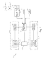
- FIG. 1 is a schematic view of a switch image control system for a vehicle.
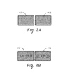
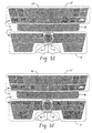
- FIG. 2A is a diagram of two switches shown in a backlight OFF condition.
- FIG. 2 B is a schematic view of the same two switches shown in a backlight ON condition.
- FIG. 3 is a schematic view of a switch image control system for an audio system and an HVAC system in a vehicle.
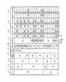
- FIG. 4 is an exemplary control matrix for selectively and independently backlighting control switches of the HVAC system and audio system of FIG. 3 .
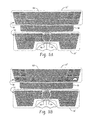
- FIGS. 5A-5G show views of HVAC control switches and audio control switches corresponding to the control matrix of FIG. 4 .
- FIG. 6 is a flow chart illustrating a switch image control method for a vehicle.
- FIG. 1 schematically illustrates a switch image control system for a vehicle, the system generally designated by reference numeral 10.
- the system 10 includes at least one first switch (e.g., switch 12) having a first image 14 viewable when a backlighting 20 is applied to the switch 12.
- the system 10 further includes at least one second switch (e.g., switch 16) having a second image 18 viewable when the backlighting 20 is applied to the second switch 16.
- Backlighting 20 can be independently applicable to either or both of the at least one first switch 12 and the at least one second switch 16.
- the first and second switches 12, 16 can employ black-out technology that allows the first image 14 to be viewable only when the backlighting 20 is applied to the first switch 12 and likewise allows the second image 18 to be viewable only when the backlighting 20 is applied to the second switch 16.
- the backlighting 20 can be applied to one or both the first and second switches based on at least one operating condition of the vehicle.
- the first and second images 14, 16 on the switches 12, 16 can be comprised of text and/or icons, which can be representative of the function of the switch.
- the first switch 12 has a black-out appearance (i.e., the first image is not viewable) when the backlighting 20 is not applied to the first switch 12.
- the second switch 16 has a black-out appearance (i.e., the second image 18 is not viewable) when the backlighting 20 is not applied to the second switch 16.
- backlighting of the images on the switches can be used to indicate the active status of the switches and/or the underlying devices or systems corresponding to the switches.
- switches 112, 116 which could be the first and second switches 12, 16, is illustrated.
- the illustrated switches 112, 116 have a black-out appearance and thus images of these switches 112, 116 are not viewable.
- the "black-out" appearance of the switches 112, 116 ( FIG. 2A ) is a blank non-descriptive appearance.
- backlighting for the illustrated switches 112, 116 is turned on and thus images of the illustrated switches 112, 116 are viewable (e.g., "AM/FM" and "(((XM)))").
- Ambient lighting, or lighting other than the backlighting has no effect on the viewability of the switches 112, 116. Accordingly, images of the switches 112, 116 cannot be seen with the provision of ambient light absent backlighting.
- the first image 14 and the second image 18 are not visible with ambient lighting when the backlighting 20 is not applied to the first switch 12 and the second switch 16.
- the first image 14 and the second image 18 are not visible even with front side lighting (e.g., vehicle cabin lighting, such as a dome light) when the backlighting 20 is not applied to the first and second switches 12, 16. Only the application of the backlighting 20 to the switches 12, 16 enables viewing of the respective images 14, 18 thereon.
- backlighting of the images 14 or 18 on the switches 12, 16 can be used to provide further information to a vehicle user. More particularly, in one embodiment, application of the backlighting 20 to the first switch 12 can correspond with an operational status of the first switch 12. Likewise, application of the backlighting 20 to the second switch 16 can correspond to the operational status of the second switch 16. In contrast to conventional images provided on vehicle switches, which allow images on the switches to be seen with ambient light, the system 10 can use the backlighting or absence of backlighting (i.e., switch images turned on or off) to reflect the operational status of the switches.
- the operational status of the first switch 12 is active when the backlighting 20 is applied to the first switch 12 and the first image 14 is illuminated, and inactive when the backlighting 20 is not applied to the first switch 12 and the first image 14 is blacked out.
- the operational status of the second switch 16 can be active when the backlighting 20 is applied to the second switch 16 and the second image 18 is illuminated, and inactive when the backlighting 20 is not applied to the second switch 16 and the second image 18 is blacked-out.
- the first switch 12 can correspond to a first vehicle sub-system 26 and the second switch 16 can correspond to a second vehicle sub-system 28.
- input from the first switch 12 e.g., depression of the first switch
- the second switch 16 can be associated with a sub-system controller 32 of the second sub-system 28 such that actuation of the second switch 16 (e.g., by depression thereof) is communicated to the sub-system controller 32.
- the backlighting source 20 can be operatively connected to the switches 12, 16 as schematically indicated at 34 and 36 such that backlighting of the switches 12, 16 via the backlighting 20 is selectively and independently controllable.
- a backlighting controller 38 is included in the system 10 for controlling backlighting 20 to the switches 12, 16.
- the backlighting controller 38 can be linked to the sub-system controllers 30, 32 of the sub-systems 26, 28, respectively, such that the backlighting controller 38 receives indications from the controllers 30, 32 as to when backlighting of the switches 12 and 16 is to be turned on and off.
- the backlighting controller 38 can additionally receive status or condition signals from other vehicle sub-systems, components, devices, etc., such as from the ignition state controller 40, particular vehicle lights or a lighting system 42 (e.g., small or parking lights, vehicle headlights, etc.), or other vehicle components or systems 44 (e.g., audio power button, hands-free call systems, etc.). This enables the backlighting of one or both of the switches 12, 16 to be based on at least one operating condition of the vehicle in which the switches 12, 16 are employed.
- a lighting system 42 e.g., small or parking lights, vehicle headlights, etc.
- vehicle components or systems 44 e.g., audio power button, hands-free call systems, etc.
- the at least one operating condition of the vehicle could be or correspond to any one or more of the following: an ignition state vehicle (e.g., as determined by the ignition state controller 40); an ON or OFF state of a backup or +B power supply of the vehicle; an ON or OFF state of a lighting system (e.g., parking lights, headlights, etc.) of the vehicle; an ON or OFF state of an audio system of the vehicle; an ON or OFF state of a HVAC system; and/or an ON or OFF state of a communication system (e.g., a hands free call system) of the vehicle.
- an ignition state vehicle e.g., as determined by the ignition state controller 40
- an ON or OFF state of a backup or +B power supply of the vehicle e.g., an ON or OFF state of a lighting system (e.g., parking lights, headlights, etc.) of the vehicle
- an ON or OFF state of an audio system of the vehicle e.g., an ON or OFF state of a
- the ignition state controller 40 can be a switch, push button or other control mechanism for changing the ignition state of the vehicle.
- the controller 40 is a keyed ignition switch having rotatable cylinder with a key slot 40a for receiving an ignition key (e.g., a conventional mechanical key or an electronic key or key fob). Once inserted, the ignition state can be changed by rotating the inserted key.
- the ignition states could include, for example, an off state, an accessory state (ACC), a run state (IG1) and a start state (IG2).
- An additional state could be a state wherein the key is removed from the key slot 40a when the ignition state controller 40 is configured to receive a key in the slot 40a.
- the key slot 40a could be replaced with a rotatable switch 40a' or other control device that is rotatable to various positions corresponding to ignition states of the vehicle and thus does not require insertion of a key.
- the ignition controller 40 could include a push button 40a", such as the type employed in a push button start system.
- changing of the ignition states could be effected by pushing the push button. For example, from an off state the button 40a" could be pressed one time to change the state to the accessory state and could be pressed again to start the vehicle and remain in a run state. A third press of the push button 40a" could change the state back to the off state. It is contemplated that other sequences, etc. could be used with the push button 40a" to change the ignition states.
- the at least one first switch is a first group of switches 12' corresponding to a first vehicle sub-system, such as an HVAC system 26'.
- the at least one second switch is a second group of switches 16' corresponding to another or second vehicle sub-system, such as audio system 28'.
- the first group of switches 12' can include a plurality of HVAC control switches 50 for controlling the HVAC system 26' through an HVAC system controller 30'.
- the second group of switches 16' can include a plurality of audio control switches 52 that control the audio system 28' through an audio system controller 32'.
- Each of the switches 50 can have respective first images (e.g., first image 14) thereon that are viewable when backlighting 20 is applied to the group of switches 12' (see FIG. 5B for example).
- each of the second group of switches 16' can have respective second images (e.g., second image 18) thereon that are viewable when backlighting 20 is applied to the second group of switches 16' (See FIG. 5C for example).
- the backlighting 20 can be applied to one or both of said first group of switches 12' and the second group of switches 16' based on at least one an ignition state of the vehicle, an ON or OFF state of a +B or backup power supply 44a of the vehicle, an ON or OFF state of a lighting system 42 (e.g., parking lights, headlights, etc.) of the vehicle, an ON or OFF state of an audio system 28' of the vehicle, an ON or OFF state of the HVAC system 26', and/or an ON or OFF state of a communication system 44b (e.g., a hands free call system) of the vehicle.
- a lighting system 42 e.g., parking lights, headlights, etc.
- a communication system 44b e.g., a hands free call system
- an audio power switch 54 which can comprise a third group 56, can have a third image thereon that is viewable when backlighting 20 is applied to the audio power switch 54 (See FIG. 5C for example).
- the backlighting 20 can be applied to the audio power switch 54 based on at least one of the ignition state of the vehicle, the ON or OFF state of a +B or backup power supply 44a of the vehicle, the ON or OFF state of a lighting system 42 (e.g., parking lights, headlights, etc.) of the vehicle, the ON or OFF state of an audio system 28' of the vehicle, an ON or OFF state of the HVAC system 26', and/or the ON or OFF state of a communication system 44b (e.g., a hands free call system) of the vehicle.
- a lighting system 42 e.g., parking lights, headlights, etc.
- a communication system 44b e.g., a hands free call system
- Backlighting of the groups of switches 12', 16', 56 can be controlled via backlighting controller 38.
- the controller 38 can independently apply the backlighting 20 to any one or more of the group of HVAC control switches 50, the group of audio control switches 52 and/or the audio power switch 54.
- a display panel 58 can be provided for displaying information associated with the audio system 28' (See FIG. 5C for example) and a display panel 60 can be provided for displaying information associated with the HVAC system 26'.
- the images on the switches 50, 52, 54 are only viewable when backlighting is provided to the groups 12', 16', 56 in which the switches are included. Absent backlighting, the switches 50, 52, 54 have a black-out appearance (see FIG. 2A ) and thus images thereon are not visible even with ambient lighting or other front side lighting.
- the states could include an off state, an accessory state, a start state and a run state.
- the states can correspond to key positions such as: removed from key slot 40a, inserted in the key slot 40a and in the OFF position, inserted in the key slot 40a and in the ACC position, and inserted in the key slot 40a and in an ON position (e.g., the IG2 position, which can be the normal engine running position).
- the ignition states can correspond to depressions of the push button (e.g., a single depression for the accessory state, a second depression for starting and running of the vehicle, and a third depression to revert to the off state).
- the only states of concern are the ACC state and the IG2 state, and backlighting is applied based on whether the ignition switch 40 is in one of these states.
- the lighting system 42 can be the vehicle's parking lights such that the backlighting is applied to one or more of the groups 12', 16', 56 in which the switches are included based on the ON or OFF state of the parking lights.
- the vehicle can be configured such that the parking lights are always on when the vehicle's headlights are turned on.
- the communication system 44b can be a hands free call system of the vehicle such that the backlighting is applied to one or more of the groups 12', 16', 56 in which the switches are included based on the ON or OFF state of the hands free call system.
- Backlighting of the group 12', 16', 56 can also correspond to an operational status of the groups of switches.
- backlighting 20 can be applied to the group 12' only when the switches 50 are active and functional.
- backlighting 20 can be applied respectively to the group 16' or 56 only when the respective switches 52, 54 are active and functional.
- backlighting of the groups 12', 16', 56 which can be done independently, can be used to indicate when switches of the groups are active. Independent backlighting allows the groups of switches 12', 16', 56 to be turned on and off independently.
- the operating conditions of the vehicle upon which the backlighting 20 is based include: the ON or OFF state of the backup or +B power supply 44a, the ignition state of the ignition switch 40 (particularly, whether the state is one of the ACC state or the IG2 state), the ON or OFF state of the audio system 28', the ON or OFF state of a hands free call system 44b, the ON or OFF state of the vehicle's parking lights 42 and the ON or OFF state of the vehicle's HVAC system 26'.
- the "+B” column 70 represents the backup function or +B power supply 44a of the vehicle.
- the "ACC” column 72 represents the accessory state of the ignition switch 40.
- the "IG2” column 74 represents the run state of the ignition switch 40.
- the "Audio Power” column 76 represents the state (i.e., ON or OFF) of the audio system 28' as controlled by the audio power button 54.
- the "HFL Mode” column 78 represents the state of the hands-free call system 44b.
- the "SMALL” column 80 represents the state of the vehicle's small or parking lights 42, which can be used as an indication representing when the vehicle's headlights are turned on.
- the “Aircom” column 82 represents the state of the vehicle's HVAC system 26', such as when that system 26' is turned on and is active, or off and inactive.
- the "VOLUME” column 84 represents the state (i.e., backlighting on or backlighting off) of the audio power button 54, which also serves to control volume of the audio system 28'.
- the "HVAC BUTTONS” column 86 represents the state (i.e., backlighting on or backlighting off) of the HVAC buttons 50 of group 12' as controlled by the backlighting controller 38.
- the AUDIO BUTTONS” column 88 represents the state (i.e., backlighting on or backlighting off) of the audio buttons 52 of group 16'.
- the HVAC switches 50 of the first group 12' are active and thus backlit via backlighting 20 at all times when the ignition switch 40 is in the run state (i.e., IG2) as indicated in column 74.
- Such backlighting can correspond to a day or night state of the vehicle.
- a day brightness setting can be applied, whereas when the headlights are ON, a dimmer night brightness level can be applied.
- the HVAC switches 50, or more particularly the images thereon are required to be visible whenever the vehicle headlights are on. Accordingly, anytime the vehicle's headlights are turned on as indicated in column 80, the HVAC buttons 50 (i.e., group 12') are turned on to one of the day or night brightness settings.
- the audio power switch 54 is backlit and active anytime the ignition switch 40 is set for the ACC state, which is indicated in column 72, or in the run state (i.e., IG2), which is indicated in column 74. Again, day and night brightness levels can be used corresponding to whether the vehicle's headlights are turned on or off which is indicated in column 80. Additionally, the audio power switch 54 can be backlit and active even when the ignition switch 40 is set for the ACC state or in the run state (columns 72 and 74) if the hands-free call system 44b is being used (e.g., a hands-free call is in progress), which is indicated in column 78.
- the audio switches 52 of group 16' can be backlit and active whenever the ignition switch 40 is set for the ACC or run key states (columns 72 and 74) and the audio system 28' is powered on, which is indicated in column 76.
- FIG. 5 the various states of the groups 12', 16', and 56 are shown corresponding to the matrix table of FIG. 4 .
- FIG. 5A illustrates all switches 50, 52, 54 of the groups 12', 16', and 56 turned off (i.e., no backlighting and thus black-out appearance).
- FIG. 5B illustrates the condition wherein the ignition state of the ignition switch 40 is off (i.e., not in the ACC or run states), but the headlights are turned on, thus the HVAC switches 50 of group 12' are backlit.
- FIG. 5C illustrates the condition where the ignition state of the ignition switch 40 is the ACC state, the audio system 28' is turned on, and the headlights are turned off as indicated by the parking lights 42.
- FIG. 5D illustrates the condition where the ignition state of the ignition switch 40 is in the ACC state, the audio system 28' is turned off, and the headlights are turned off; thus, none of the groups 12', 16', 56 of switches 50, 52, 54 are backlit or active (i.e., all are blacked-out).
- FIG. 5E illustrates the condition where the ignition switch 40 is in the run position (i.e., IG2), the audio system 28' is turned off, and the headlights are on or off. As shown, in this condition, the switches 50 of group 12' are backlit and active.
- FIG. IG2 run position
- FIG. 5F illustrates the condition where the ignition state of the ignition switch 40 is the run state, the audio system 28' is on, and the headlights are turned on or off. In this condition, all groups 12', 16', 56 of switches 52, 54 are backlit and active.
- FIG. 5G illustrates the condition where the ignition state of the ignition switch 40 is the ACC position, the audio system 28' is on and the headlights are turned on. In this condition, all groups 12', 16', 56 of switches 52, 54 are backlit and active.
- a switch image control method for a vehicle will now be described.
- at least one first switch 12 (or the switches 50 of the first group 12') is provided having a first image 14 (S100) and at least one second switch 16 (or the switches 52 of the second group 16') is provided having a second image 18 (S102).
- the method can further include the provision of a third switch (e.g., the audio power switch 54) having the third image thereon (S104).
- One or more of the first switch 12, the second switch 16 and the third switch 54 are selectively and independently backlit to illuminate the images thereon based on at least one operating condition of the vehicle (S106).
- the at least one operating condition can include one or more of: the state of the ignition switch 40 , the ON or OFF state of a +B or backup power supply 44a, the ON or OFF state of a lighting system 42 (e.g., parking lights, headlights, etc.), the ON or OFF state of the audio system 28', the ON or OFF state of the HVAC system 26', and/or the ON or OFF state of a communication system 44b.
- the first image 14 is blacked-out (S108).
- the second image 18 is blacked-out (S110).
- the third image is blacked-out (S112).
- Backlighting of the switches 12, 16, 54 to illuminate the respective first, second and third images occurs only when the respective switches 12, 16, 54 are active. Such backlighting can be in accordance with the control matrix of FIG. 4 .
Landscapes
- Engineering & Computer Science (AREA)
- Mechanical Engineering (AREA)
- Chemical & Material Sciences (AREA)
- Combustion & Propulsion (AREA)
- Transportation (AREA)
- Arrangements Of Lighting Devices For Vehicle Interiors, Mounting And Supporting Thereof, Circuits Therefore (AREA)
- Fittings On The Vehicle Exterior For Carrying Loads, And Devices For Holding Or Mounting Articles (AREA)
- Circuit Arrangement For Electric Light Sources In General (AREA)
Abstract
Description
- Exemplary embodiments herein generally relate to vehicle control switches, and more particularly relate to selectively illuminated images on vehicle control switches.
- Conventional vehicle control switches, such as audio and HVAC switches, typically have printed or etched text and/or icons thereon. The text and/or icons identify the function of the particular switch. The printed or etched text and/or icons are generally always visible if sufficient ambient light is present within the vehicle cabin. Sometimes the printing or etching is also backlightable for nighttime viewing in addition to being viewable with ambient light during the daytime.
- More recently, some vehicle manufacturers have been using "black-out" technology. Such technology allows an image to be viewable only when it is backlit. That is, the image is not viewable regardless of the amount of ambient or other light present. Rather, viewing of the image is only possible when backlighting of the image occurs.
- Conventional uses of such black-out technology in vehicles include providing an indicator of the status or condition of a vehicle component. For example, an OFF indicator is only viewable via backlighting when an associated passenger airbag is disabled or non-functional. Another vehicle manufacturer presently employs touch sensor switches on the driver's side door. These switches include images that are only viewable upon backlighting. To actuate backlighting of these switches, which can be used to unlock the vehicle when a predetermined code is entered through the switches, the user swipes his or her hand over the switches.
- Still other others have been known to employ touch sensor switches for audio and HVAC systems in vehicles that employ black-out technology. For example, one known control panel includes mode selector buttons that, when selected, change the operating mode of a control switch (e.g., to HVAC mode or audio mode). In addition, certain switches and displays around the control switch become visible on the control panel corresponding to the selected selector button and its operating mode. Other switches and displays are not visible until their corresponding selector button (and mode) is selected.
- In accordance with one aspect, a switch image control system is provided for a vehicle including at least one first switch having a first image viewable when a backlighting is applied to the at least one first switch and at least one second switch having a second image viewable when the backlighting is applied to the at least one second switch. The backlighting is independently applicable to either or both of the at least one first switch and the at least one second switch.
- According to another aspect, a switch image control method is provided for a vehicle. In the method according to this aspect, at least one first switch having a first image is provided. Also, at least one second switch having a second image is provided. One or both of the at least one first switch and the at least one second switch are selectively and independently backlit to illuminate the first image and/or the second image.
- According to yet another aspect, a switch image control system is provided for a vehicle. More particularly, in accordance with this aspect, the system includes at least one first switch having a first image viewable when a backlighting is applied to the at least one first switch and at least one second switch having a second image viewable when the backlighting is applied to the at least one second switch. The backlighting is applied to one or both the at least one first switch and the at least one second switch based on at least one operating condition of the vehicle. The at least one operating condition can correspond to an ON or OFF state of a backup power supply of the vehicle. The at least one operating condition can correspond to an ON or OFF state of a lighting system of the vehicle. The lighting system can be parking lights of the vehicle and the backlighting can be applied to one or both the at least one first switch and the at least one second switch based on an ON or OFF state of the parking lights. The at least one operating condition can correspond to an ON or OFF state of an audio system of the vehicle or to an ON or OFF state of an HVAC system of the vehicle. The at least one operating condition can correspond to an ON or OFF state of a communication system of the vehicle. Also, the at least one operating condition can correspond to an ON or OFF state of a backup power supply of the vehicle, an ON or OFF state of a lighting system of the vehicle, an ON or OFF state of parking lights of the vehicle when the lighting system is parking lights, an ON or OFF state of an audio system of the vehicle, an ON or OFF state of an HVAC system of the vehicle, and/or an ON or OFF state of a communication system of the vehicle.
- According to still yet another aspect, a switch image control system for a vehicle includes a first group of switches having first images viewable thereon when a backlighting is applied thereto and a second group of switches having second images viewable thereon when the backlighting is applied thereto. The first group of switches corresponds to a first vehicle sub-system and the second group of switches corresponds to a second vehicle sub-system. The backlighting is applied to one or both of the first group of switches and the second group of switches based on at least one of: an ignition state of the vehicle, an ON or OFF state of a backup power supply of the vehicle, an ON or OFF state of a lighting system of the vehicle, an ON or OFF state of an audio system of the vehicle, an ON or OFF state of a HVAC system and an ON or OFF state of a communication system of the vehicle. The first group of switches can include HVAC control switches and the first vehicle sub-system can be an HVAC system, and the second group of switches can include audio control switches and the second vehicle sub-system can be an audio system. The switch image control system can further include an audio power switch having a third image viewable when said backlighting is applied to the audio power switch based on at least one of: the ignition state of the vehicle, the ON or OFF state of the backup power supply of the vehicle, the ON or OFF state of the lighting system of the vehicle, the ON or OFF state of an audio system of the vehicle, an ON or OFF state of a HVAC system, and the ON or OFF state of the communication system of the vehicle. The backlighting can be applied to each of the first group of switches, the second group of switches and the audio power button switch based on each of the ignition state of the vehicle, the ON or OFF state of the backup power supply of the vehicle, the ON or OFF state of a lighting system of the vehicle, the ON or OFF state of the audio system of the vehicle, an ON or OFF state of a HVAC system, and the ON or OFF state of the communication system of the vehicle.
- According to a further aspect, a switch image control method is provided for a vehicle. In the method according to this aspect, at least one first switch having a first image is provided and at least one second switch having a second image is provided. One or both of the at least one first switch and the at least one second switch is selectively and independently backlit to, respectively, illuminate the first image and illuminate the second image based on at least one operating condition of the vehicle.
-
FIG. 1 is a schematic view of a switch image control system for a vehicle. -
FIG. 2A is a diagram of two switches shown in a backlight OFF condition. -
FIG. 2 B is a schematic view of the same two switches shown in a backlight ON condition. -
FIG. 3 is a schematic view of a switch image control system for an audio system and an HVAC system in a vehicle. -
FIG. 4 is an exemplary control matrix for selectively and independently backlighting control switches of the HVAC system and audio system ofFIG. 3 . -
FIGS. 5A-5G show views of HVAC control switches and audio control switches corresponding to the control matrix ofFIG. 4 . -
FIG. 6 is a flow chart illustrating a switch image control method for a vehicle. - Referring now to the drawings wherein the showings are for the purposes of illustrating one or more exemplary embodiments,
FIG. 1 schematically illustrates a switch image control system for a vehicle, the system generally designated byreference numeral 10. Thesystem 10 includes at least one first switch (e.g., switch 12) having afirst image 14 viewable when abacklighting 20 is applied to theswitch 12. Thesystem 10 further includes at least one second switch (e.g., switch 16) having asecond image 18 viewable when thebacklighting 20 is applied to thesecond switch 16.Backlighting 20 can be independently applicable to either or both of the at least onefirst switch 12 and the at least onesecond switch 16. In particular, the first andsecond switches first image 14 to be viewable only when thebacklighting 20 is applied to thefirst switch 12 and likewise allows thesecond image 18 to be viewable only when thebacklighting 20 is applied to thesecond switch 16. In an exemplary embodiment, as will be described in more detail below, thebacklighting 20 can be applied to one or both the first and second switches based on at least one operating condition of the vehicle. - The first and
second images switches first switch 12 has a black-out appearance (i.e., the first image is not viewable) when thebacklighting 20 is not applied to thefirst switch 12. Similarly, thesecond switch 16 has a black-out appearance (i.e., thesecond image 18 is not viewable) when thebacklighting 20 is not applied to thesecond switch 16. As will be described in more detail below, backlighting of the images on the switches can be used to indicate the active status of the switches and/or the underlying devices or systems corresponding to the switches. - With additional reference to
FIGS. 2A and 2B , a pair ofswitches second switches FIG. 2A , the illustratedswitches switches switches 112, 116 (FIG. 2A ) is a blank non-descriptive appearance. InFIG. 2B , backlighting for the illustratedswitches switches switches switches - Likewise, with reference back to
FIG. 1 , thefirst image 14 and thesecond image 18 are not visible with ambient lighting when thebacklighting 20 is not applied to thefirst switch 12 and thesecond switch 16. In addition to ambient lighting, thefirst image 14 and thesecond image 18 are not visible even with front side lighting (e.g., vehicle cabin lighting, such as a dome light) when thebacklighting 20 is not applied to the first andsecond switches backlighting 20 to theswitches respective images - In addition to providing a neat styling effect, backlighting of the
images switches 12, 16 (or the absence thereof) can be used to provide further information to a vehicle user. More particularly, in one embodiment, application of thebacklighting 20 to thefirst switch 12 can correspond with an operational status of thefirst switch 12. Likewise, application of thebacklighting 20 to thesecond switch 16 can correspond to the operational status of thesecond switch 16. In contrast to conventional images provided on vehicle switches, which allow images on the switches to be seen with ambient light, thesystem 10 can use the backlighting or absence of backlighting (i.e., switch images turned on or off) to reflect the operational status of the switches. In one embodiment, the operational status of thefirst switch 12 is active when thebacklighting 20 is applied to thefirst switch 12 and thefirst image 14 is illuminated, and inactive when thebacklighting 20 is not applied to thefirst switch 12 and thefirst image 14 is blacked out. Similarly, the operational status of thesecond switch 16 can be active when thebacklighting 20 is applied to thesecond switch 16 and thesecond image 18 is illuminated, and inactive when thebacklighting 20 is not applied to thesecond switch 16 and thesecond image 18 is blacked-out. - As shown in
FIG. 1 , thefirst switch 12 can correspond to afirst vehicle sub-system 26 and thesecond switch 16 can correspond to asecond vehicle sub-system 28. As is known and understood by those skilled in the art, input from the first switch 12 (e.g., depression of the first switch) can be received or communicated to asub-system controller 30 of thefirst sub-system 26. Similarly, thesecond switch 16 can be associated with asub-system controller 32 of thesecond sub-system 28 such that actuation of the second switch 16 (e.g., by depression thereof) is communicated to thesub-system controller 32. Thebacklighting source 20 can be operatively connected to theswitches switches backlighting 20 is selectively and independently controllable. In one embodiment, abacklighting controller 38 is included in thesystem 10 for controllingbacklighting 20 to theswitches backlighting controller 38 can be linked to thesub-system controllers sub-systems backlighting controller 38 receives indications from thecontrollers switches - The
backlighting controller 38 can additionally receive status or condition signals from other vehicle sub-systems, components, devices, etc., such as from theignition state controller 40, particular vehicle lights or a lighting system 42 (e.g., small or parking lights, vehicle headlights, etc.), or other vehicle components or systems 44 (e.g., audio power button, hands-free call systems, etc.). This enables the backlighting of one or both of theswitches switches - The
ignition state controller 40 can be a switch, push button or other control mechanism for changing the ignition state of the vehicle. In one example (the illustrated embodiment), thecontroller 40 is a keyed ignition switch having rotatable cylinder with akey slot 40a for receiving an ignition key (e.g., a conventional mechanical key or an electronic key or key fob). Once inserted, the ignition state can be changed by rotating the inserted key. The ignition states could include, for example, an off state, an accessory state (ACC), a run state (IG1) and a start state (IG2). An additional state could be a state wherein the key is removed from thekey slot 40a when theignition state controller 40 is configured to receive a key in theslot 40a. - In an alternate embodiment, the
key slot 40a could be replaced with arotatable switch 40a' or other control device that is rotatable to various positions corresponding to ignition states of the vehicle and thus does not require insertion of a key. In another alternate embodiment, theignition controller 40 could include apush button 40a", such as the type employed in a push button start system. In this embodiment, changing of the ignition states could be effected by pushing the push button. For example, from an off state thebutton 40a" could be pressed one time to change the state to the accessory state and could be pressed again to start the vehicle and remain in a run state. A third press of thepush button 40a" could change the state back to the off state. It is contemplated that other sequences, etc. could be used with thepush button 40a" to change the ignition states. - With reference to
FIG. 3 , one implementation of the above-describedsystem 10 is illustrated for a vehicle's HVAC system 26' and audio system 28'. InFIG. 3 , the at least one first switch is a first group of switches 12' corresponding to a first vehicle sub-system, such as an HVAC system 26'. The at least one second switch is a second group of switches 16' corresponding to another or second vehicle sub-system, such as audio system 28'. As illustrated, the first group of switches 12' can include a plurality of HVAC control switches 50 for controlling the HVAC system 26' through an HVAC system controller 30'. The second group of switches 16' can include a plurality of audio control switches 52 that control the audio system 28' through an audio system controller 32'. - Each of the
switches 50 can have respective first images (e.g., first image 14) thereon that are viewable when backlighting 20 is applied to the group of switches 12' (seeFIG. 5B for example). Similarly, each of the second group of switches 16' can have respective second images (e.g., second image 18) thereon that are viewable when backlighting 20 is applied to the second group of switches 16' (SeeFIG. 5C for example). As will be described in more detail below, thebacklighting 20 can be applied to one or both of said first group of switches 12' and the second group of switches 16' based on at least one an ignition state of the vehicle, an ON or OFF state of a +B orbackup power supply 44a of the vehicle, an ON or OFF state of a lighting system 42 (e.g., parking lights, headlights, etc.) of the vehicle, an ON or OFF state of an audio system 28' of the vehicle, an ON or OFF state of the HVAC system 26', and/or an ON or OFF state of acommunication system 44b (e.g., a hands free call system) of the vehicle. - Also in the embodiment illustrated in
FIG. 3 , anaudio power switch 54, which can comprise athird group 56, can have a third image thereon that is viewable when backlighting 20 is applied to the audio power switch 54 (SeeFIG. 5C for example). Like the groups 12' and 16', thebacklighting 20 can be applied to theaudio power switch 54 based on at least one of the ignition state of the vehicle, the ON or OFF state of a +B orbackup power supply 44a of the vehicle, the ON or OFF state of a lighting system 42 (e.g., parking lights, headlights, etc.) of the vehicle, the ON or OFF state of an audio system 28' of the vehicle, an ON or OFF state of the HVAC system 26', and/or the ON or OFF state of acommunication system 44b (e.g., a hands free call system) of the vehicle. - Backlighting of the groups of
switches 12', 16', 56 can be controlled viabacklighting controller 38. In particular, thecontroller 38 can independently apply thebacklighting 20 to any one or more of the group of HVAC control switches 50, the group of audio control switches 52 and/or theaudio power switch 54. In addition, in the illustrated embodiment, adisplay panel 58 can be provided for displaying information associated with the audio system 28' (SeeFIG. 5C for example) and adisplay panel 60 can be provided for displaying information associated with the HVAC system 26'. The images on theswitches groups 12', 16', 56 in which the switches are included. Absent backlighting, theswitches FIG. 2A ) and thus images thereon are not visible even with ambient lighting or other front side lighting. - When the backlighting is based on the ignition state, the states could include an off state, an accessory state, a start state and a run state. When used with a key-type ignition switch or a rotatable switch, the states can correspond to key positions such as: removed from
key slot 40a, inserted in thekey slot 40a and in the OFF position, inserted in thekey slot 40a and in the ACC position, and inserted in thekey slot 40a and in an ON position (e.g., the IG2 position, which can be the normal engine running position). When used with a push button (e.g.,push button 40") of a push button start system, the ignition states can correspond to depressions of the push button (e.g., a single depression for the accessory state, a second depression for starting and running of the vehicle, and a third depression to revert to the off state). In one exemplary embodiment, the only states of concern are the ACC state and the IG2 state, and backlighting is applied based on whether theignition switch 40 is in one of these states. When the backlighting is based on the ON or OFF state of avehicle lighting system 42, thelighting system 42 can be the vehicle's parking lights such that the backlighting is applied to one or more of thegroups 12', 16', 56 in which the switches are included based on the ON or OFF state of the parking lights. As is known by those skilled in the art, the vehicle can be configured such that the parking lights are always on when the vehicle's headlights are turned on. When the backlighting is based on the ON or OFF state of acommunication system 44b of the vehicle, thecommunication system 44b can be a hands free call system of the vehicle such that the backlighting is applied to one or more of thegroups 12', 16', 56 in which the switches are included based on the ON or OFF state of the hands free call system. - Backlighting of the
group 12', 16', 56 can also correspond to an operational status of the groups of switches. For example, backlighting 20 can be applied to the group 12' only when theswitches 50 are active and functional. Likewise, backlighting 20 can be applied respectively to thegroup 16' or 56 only when therespective switches groups 12', 16', 56, which can be done independently, can be used to indicate when switches of the groups are active. Independent backlighting allows the groups ofswitches 12', 16', 56 to be turned on and off independently. - With reference to
FIG. 4 , one exemplary control matrix is illustrated for thebacklighting controller 38, though it is to be appreciated that other control matrices could alternately be employed. In the illustrated control matrix, the operating conditions of the vehicle upon which thebacklighting 20 is based include: the ON or OFF state of the backup or +B power supply 44a, the ignition state of the ignition switch 40 (particularly, whether the state is one of the ACC state or the IG2 state), the ON or OFF state of the audio system 28', the ON or OFF state of a handsfree call system 44b, the ON or OFF state of the vehicle'sparking lights 42 and the ON or OFF state of the vehicle's HVAC system 26'. - In the control matrix, the "+B"
column 70 represents the backup function or +B power supply 44a of the vehicle. The "ACC"column 72 represents the accessory state of theignition switch 40. The "IG2"column 74 represents the run state of theignition switch 40. The "Audio Power"column 76 represents the state (i.e., ON or OFF) of the audio system 28' as controlled by theaudio power button 54. The "HFL Mode"column 78 represents the state of the hands-free call system 44b. The "SMALL"column 80 represents the state of the vehicle's small orparking lights 42, which can be used as an indication representing when the vehicle's headlights are turned on. The "Aircom"column 82 represents the state of the vehicle's HVAC system 26', such as when that system 26' is turned on and is active, or off and inactive. The "VOLUME"column 84 represents the state (i.e., backlighting on or backlighting off) of theaudio power button 54, which also serves to control volume of the audio system 28'. The "HVAC BUTTONS"column 86 represents the state (i.e., backlighting on or backlighting off) of theHVAC buttons 50 of group 12' as controlled by thebacklighting controller 38. The AUDIO BUTTONS"column 88 represents the state (i.e., backlighting on or backlighting off) of theaudio buttons 52 of group 16'. - As will be appreciated from the control matrix of
FIG. 4 , the HVAC switches 50 of the first group 12' are active and thus backlit via backlighting 20 at all times when theignition switch 40 is in the run state (i.e., IG2) as indicated incolumn 74. Such backlighting can correspond to a day or night state of the vehicle. For example, when the vehicle's headlights are turned OFF as indicated incolumn 80, a day brightness setting can be applied, whereas when the headlights are ON, a dimmer night brightness level can be applied. Sometimes per regulations, the HVAC switches 50, or more particularly the images thereon, are required to be visible whenever the vehicle headlights are on. Accordingly, anytime the vehicle's headlights are turned on as indicated incolumn 80, the HVAC buttons 50 (i.e., group 12') are turned on to one of the day or night brightness settings. - As indicated in
column 88, theaudio power switch 54 is backlit and active anytime theignition switch 40 is set for the ACC state, which is indicated incolumn 72, or in the run state (i.e., IG2), which is indicated incolumn 74. Again, day and night brightness levels can be used corresponding to whether the vehicle's headlights are turned on or off which is indicated incolumn 80. Additionally, theaudio power switch 54 can be backlit and active even when theignition switch 40 is set for the ACC state or in the run state (columns 72 and 74) if the hands-free call system 44b is being used (e.g., a hands-free call is in progress), which is indicated incolumn 78. The audio switches 52 of group 16' can be backlit and active whenever theignition switch 40 is set for the ACC or run key states (columns 72 and 74) and the audio system 28' is powered on, which is indicated incolumn 76. - Turning to
FIG. 5 , the various states of thegroups 12', 16', and 56 are shown corresponding to the matrix table ofFIG. 4 . In particular,FIG. 5A illustrates all switches 50, 52, 54 of thegroups 12', 16', and 56 turned off (i.e., no backlighting and thus black-out appearance).FIG. 5B illustrates the condition wherein the ignition state of theignition switch 40 is off (i.e., not in the ACC or run states), but the headlights are turned on, thus the HVAC switches 50 of group 12' are backlit.FIG. 5C illustrates the condition where the ignition state of theignition switch 40 is the ACC state, the audio system 28' is turned on, and the headlights are turned off as indicated by the parking lights 42. As shown, in this condition, theswitches 52 of group 16' are backlit and active.FIG. 5D illustrates the condition where the ignition state of theignition switch 40 is in the ACC state, the audio system 28' is turned off, and the headlights are turned off; thus, none of thegroups 12', 16', 56 ofswitches FIG. 5E illustrates the condition where theignition switch 40 is in the run position (i.e., IG2), the audio system 28' is turned off, and the headlights are on or off. As shown, in this condition, theswitches 50 of group 12' are backlit and active.FIG. 5F illustrates the condition where the ignition state of theignition switch 40 is the run state, the audio system 28' is on, and the headlights are turned on or off. In this condition, allgroups 12', 16', 56 ofswitches FIG. 5G illustrates the condition where the ignition state of theignition switch 40 is the ACC position, the audio system 28' is on and the headlights are turned on. In this condition, allgroups 12', 16', 56 ofswitches - According to the foregoing, and with reference to
FIG. 6 , a switch image control method for a vehicle will now be described. In the illustrated method, at least one first switch 12 (or theswitches 50 of the first group 12') is provided having a first image 14 (S100) and at least one second switch 16 (or theswitches 52 of the second group 16') is provided having a second image 18 (S102). The method can further include the provision of a third switch (e.g., the audio power switch 54) having the third image thereon (S104). One or more of thefirst switch 12, thesecond switch 16 and thethird switch 54 are selectively and independently backlit to illuminate the images thereon based on at least one operating condition of the vehicle (S106). As already described, the at least one operating condition can include one or more of: the state of theignition switch 40 , the ON or OFF state of a +B orbackup power supply 44a, the ON or OFF state of a lighting system 42 (e.g., parking lights, headlights, etc.), the ON or OFF state of the audio system 28', the ON or OFF state of the HVAC system 26', and/or the ON or OFF state of acommunication system 44b. - When no backlighting is applied to the
first switch 12, thefirst image 14 is blacked-out (S108). When no backlighting is applied to thesecond switch 16, thesecond image 18 is blacked-out (S110). Likewise, when no backlighting is applied to thethird switch 54, the third image is blacked-out (S112). Backlighting of theswitches respective switches FIG. 4 . - It will be appreciated that several of the above-disclosed and other features and functions, or alternative thereof, may be desirably combined into many other different systems or applications. Also that various presently unforeseen or unanticipated alternatives, modifications, variations or improvements therein may be subsequently made by those skilled in the art which are also intended to be encompassed by the following claims.
Claims (13)
- A switch image control system for a vehicle, comprising:at least one first switch having a first image viewable when a backlighting is applied to said at least one first switch; andat least one second switch having a second image viewable when said backlighting is applied to said at least one second switch, said backlighting applied to one or both said at least one first switch and said at least one second switch based on at least one operating condition of the vehicle.
- The switch image control system of claim 1 wherein said at least one operating condition corresponds to an ignition state of the vehicle.
- The switch image control system of claim 2 wherein said ignition state is based on an ignition switch having a key slot and said state include one or more of:removed from a key slot, inserted in said key slot and in an OFF position, inserted in said key slot and in an ACC position, and inserted in said key slot and in an ON position.
- The switch image control system of claim 2 wherein said ignition state includes an off state, an accessory ON state and a run state.
- The switch image control system of claim 4 wherein the ignition state is determined by a push button of a push button start system.
- The switch image control system of claim 3 wherein said at least one key position includes: being inserted in said key slot and being in said ACC position, and being inserted in said key slot and being in said ON position, and wherein said backlighting is applied to one or both said at least one first switch and said at least one second switch based on whether a key is inserted in said key slot and said ignition switch is in said ACC position and based on whether said key is inserted in said key slot and said ignition switch is in said ON position.
- The switch image control system of claim 1 wherein said at least one operating condition corresponds to an ON or OFF state of a backup power supply of the vehicle, an ON or OFF state of a lighting system of the vehicle, an ON or OFF state of parking lights of the vehicle when said lighting system is parking lights, an ON or OFF state of an audio system of the vehicle, an ON or OFF state of an HVAC system of the vehicle, and/or an ON or OFF state of a communication system of the vehicle.
- The switch image control system of claim 7 wherein said communication system is a hands free call system of the vehicle, and wherein said backlighting is applied to one or both said at least one first switch and said at least one second switch based on an ON or OFF state of said hands free call system.
- The switch image control system of claim 1 wherein said first image is viewable only when said backlighting is applied to said at least one first switch, otherwise said at least one first switch has a black-out appearance, and said second image is viewable only when said backlighting is applied to said at least one second switch, otherwise said at least one second switch has a black-out appearance.
- The switch image control system of claim 1 wherein said first image and said second image are not visible with ambient lighting or front side lighting when said backlighting is not applied to said at least one first switch and said at least one second switch.
- The switch image control system of claim 1 wherein application of said backlighting to said at least one first switch corresponds with an operational status of said at least one first switch, and application of said backlighting to said at least one second switch corresponds to an operational status of said at least one second switch.
- The switch image control method of claim 18 wherein said at least one operation condition of the vehicle includes at least one of: an ignition state of the vehicle, an ON or OFF state of a backup power supply of the vehicle, an ON or OFF state of a lighting system of the vehicle, an ON or OFF state of an audio system of the vehicle, an ON or OFF state of a HVAC system, and an ON or OFF state of a communication system of the vehicle.
- The switch image control method of claim 18 further including:providing an audio power switch having a third image; andselectively and independently backlighting said audio power switch to illuminate said third image based on said at least one operating condition of the vehicle.
Applications Claiming Priority (2)
| Application Number | Priority Date | Filing Date | Title |
|---|---|---|---|
| US16689909P | 2009-04-06 | 2009-04-06 | |
| US12/614,880 US8639407B2 (en) | 2009-04-06 | 2009-11-09 | Switch image control system and method |
Publications (2)
| Publication Number | Publication Date |
|---|---|
| EP2246215A1 true EP2246215A1 (en) | 2010-11-03 |
| EP2246215B1 EP2246215B1 (en) | 2012-12-19 |
Family
ID=42313572
Family Applications (1)
| Application Number | Title | Priority Date | Filing Date |
|---|---|---|---|
| EP10155580A Not-in-force EP2246215B1 (en) | 2009-04-06 | 2010-03-05 | Switch image control system and method |
Country Status (3)
| Country | Link |
|---|---|
| US (2) | US8639407B2 (en) |
| EP (1) | EP2246215B1 (en) |
| CN (1) | CN101856992B (en) |
Families Citing this family (6)
| Publication number | Priority date | Publication date | Assignee | Title |
|---|---|---|---|---|
| US20120283914A1 (en) * | 2011-05-05 | 2012-11-08 | Karwaczynski Krzysztof W | Vehicle steering wheel control system having integrated electronic control unit |
| US8841995B2 (en) | 2012-09-14 | 2014-09-23 | Nissan North America, Inc. | Stealth mode for indicia used to display vehicle operation |
| JP6277975B2 (en) * | 2015-02-26 | 2018-02-14 | トヨタ自動車株式会社 | Idling stop control device |
| DE112017002168B4 (en) | 2016-06-10 | 2020-02-20 | Fujifilm Corporation | Adjustment device and camera |
| US10303339B2 (en) * | 2016-08-26 | 2019-05-28 | Toyota Motor Engineering & Manufacturing North America, Inc. | Multi-information display software switch strategy |
| CN113135141B (en) * | 2020-01-20 | 2023-06-23 | 长城汽车股份有限公司 | A control method and device for a vehicle switch backlight module |
Citations (4)
| Publication number | Priority date | Publication date | Assignee | Title |
|---|---|---|---|---|
| WO2000034067A1 (en) * | 1998-12-04 | 2000-06-15 | Ford Motor Company Limited | Automotive control panel |
| DE10114588A1 (en) * | 2001-03-24 | 2002-10-10 | Schneider Eng Gmbh | Back lit plastic part for display and/or function control elements consists of transparent plastic with thin metal coating and point or flat illumination body(ies) behind or in plastic part |
| WO2008061786A1 (en) * | 2006-11-24 | 2008-05-29 | Preh Gmbh | Control element comprising a metallic coating for a motor vehicle |
| US20090065336A1 (en) * | 2007-09-12 | 2009-03-12 | Bayley James P | Reconfigurable switch array using multi-layered film |
Family Cites Families (20)
| Publication number | Priority date | Publication date | Assignee | Title |
|---|---|---|---|---|
| US5381074A (en) * | 1993-06-01 | 1995-01-10 | Chrysler Corporation | Self calibrating lighting control system |
| GB9522135D0 (en) | 1995-10-30 | 1996-01-03 | John Mcgavigan Holdings Limite | Display panels |
| US6240347B1 (en) * | 1998-10-13 | 2001-05-29 | Ford Global Technologies, Inc. | Vehicle accessory control with integrated voice and manual activation |
| US6575607B1 (en) * | 2000-04-03 | 2003-06-10 | Delphi Technologies, Inc. | User controllable color lighting in a vehicle instrument cluster |
| US6850209B2 (en) * | 2000-12-29 | 2005-02-01 | Vert, Inc. | Apparatuses, methods, and computer programs for displaying information on vehicles |
| JP4734743B2 (en) * | 2001-03-30 | 2011-07-27 | 株式会社デンソー | Vehicle instrument |
| JP2004058828A (en) * | 2002-07-29 | 2004-02-26 | Denso Corp | Vehicle front display system |
| DE10260831B3 (en) | 2002-12-23 | 2004-04-15 | Lisa Dräxlmaier GmbH | Illumination system for automobile display has carrier with point light sources and surface illumination device and transparent cover with back-lit symbols |
| JP3924548B2 (en) * | 2003-04-22 | 2007-06-06 | 株式会社東海理化電機製作所 | Window glass pinching presence / absence detection device |
| US7106005B2 (en) * | 2003-11-18 | 2006-09-12 | Nissan Motor Co., Ltd. | Vehicle room lamp control device and vehicle room lamp control method |
| US7904220B2 (en) * | 2004-07-26 | 2011-03-08 | GM Global Technology Operations LLC | Vehicular multifunction control system |
| US7009504B1 (en) * | 2004-08-10 | 2006-03-07 | Lear Corporation | Reconfigurable vehicle accessory control panel |
| US7246911B2 (en) | 2004-10-07 | 2007-07-24 | Yazaki North America, Inc. | Instrument cluster with hidden telltale indicators |
| US7113077B2 (en) * | 2005-01-21 | 2006-09-26 | Autotronic Controls Corporation | System and method for providing a display utilizing a fast photon indicator |
| EP2703207A3 (en) | 2006-01-06 | 2014-07-02 | Johnson Controls Technology Company | Reconfigurable instrument cluster |
| US7994907B2 (en) * | 2006-03-31 | 2011-08-09 | Sharp Kabushiki Kaisha | Image information generation device, display control device using the same, information display system for travel body, module for driver seat, and travel body |
| JP4333776B2 (en) | 2007-05-16 | 2009-09-16 | 株式会社デンソー | control panel |
| US7876058B2 (en) * | 2007-06-22 | 2011-01-25 | Dell Products L.P. | Systems and methods for backlighting image displays |
| US8509987B2 (en) * | 2009-11-11 | 2013-08-13 | Benjamin Resner | Methods and apparatus for automatic internet logging and social comparison of vehicular driving behavior |
| US8258704B2 (en) * | 2009-12-28 | 2012-09-04 | Brant Gregory S | Vehicle lighting display system |
-
2009
- 2009-11-09 US US12/614,880 patent/US8639407B2/en not_active Expired - Fee Related
-
2010
- 2010-03-05 EP EP10155580A patent/EP2246215B1/en not_active Not-in-force
- 2010-04-06 CN CN201010156579.2A patent/CN101856992B/en not_active Expired - Fee Related
-
2013
- 2013-12-20 US US14/136,085 patent/US9241390B2/en active Active
Patent Citations (4)
| Publication number | Priority date | Publication date | Assignee | Title |
|---|---|---|---|---|
| WO2000034067A1 (en) * | 1998-12-04 | 2000-06-15 | Ford Motor Company Limited | Automotive control panel |
| DE10114588A1 (en) * | 2001-03-24 | 2002-10-10 | Schneider Eng Gmbh | Back lit plastic part for display and/or function control elements consists of transparent plastic with thin metal coating and point or flat illumination body(ies) behind or in plastic part |
| WO2008061786A1 (en) * | 2006-11-24 | 2008-05-29 | Preh Gmbh | Control element comprising a metallic coating for a motor vehicle |
| US20090065336A1 (en) * | 2007-09-12 | 2009-03-12 | Bayley James P | Reconfigurable switch array using multi-layered film |
Also Published As
| Publication number | Publication date |
|---|---|
| US20100256855A1 (en) | 2010-10-07 |
| US20140103803A1 (en) | 2014-04-17 |
| EP2246215B1 (en) | 2012-12-19 |
| CN101856992A (en) | 2010-10-13 |
| US9241390B2 (en) | 2016-01-19 |
| CN101856992B (en) | 2016-01-20 |
| US8639407B2 (en) | 2014-01-28 |
Similar Documents
| Publication | Publication Date | Title |
|---|---|---|
| US9241390B2 (en) | Switch image control system and method | |
| US7141748B2 (en) | Multifunctional switch with indicator | |
| EP1569073B1 (en) | Single knob multifunction controller and display unit | |
| JP4843609B2 (en) | Operating elements for cars | |
| US20100222972A1 (en) | Method and Apparatus for Shift-by-Wire in a Motor Vehicle | |
| CN102079278A (en) | In-vehicle display system | |
| GB2496238A (en) | Instrument arrangement for a motor vehicle | |
| CN114248624A (en) | Display device for vehicle | |
| KR20010043448A (en) | Control device | |
| JP5909329B2 (en) | Vehicle display device | |
| US20070227795A1 (en) | Operating and Display Unit | |
| US10443725B2 (en) | Shift-by-wire module illumination strategy for vehicle | |
| US8466633B2 (en) | Illumination controlling device for vehicle | |
| JP2020131830A (en) | Driving support device | |
| US7973484B2 (en) | Method and device for automatically switching to main beam | |
| CN117715781B (en) | Display systems for vehicles and methods for optically highlighting different operating states in vehicles. | |
| JP2018185641A (en) | Vehicular information providing device | |
| JP2006256377A (en) | Vehicle information display device | |
| CN105813879A (en) | Method and device for transferring an electronic display device into a secured state, and controller for controlling an electronic display device | |
| JP2005343343A (en) | Vehicle display device | |
| Pryor Jr | Futuristic Instrument Panel | |
| JP2006040683A (en) | Switch display device for vehicle | |
| KR20120119599A (en) | Display device of instrument cluster for car and methods for controlling the display device | |
| JP2013249042A (en) | Display device for vehicle | |
| JP2008241645A (en) | Display device and alarm display method |
Legal Events
| Date | Code | Title | Description |
|---|---|---|---|
| PUAI | Public reference made under article 153(3) epc to a published international application that has entered the european phase |
Free format text: ORIGINAL CODE: 0009012 |
|
| AK | Designated contracting states |
Kind code of ref document: A1 Designated state(s): AT BE BG CH CY CZ DE DK EE ES FI FR GB GR HR HU IE IS IT LI LT LU LV MC MK MT NL NO PL PT RO SE SI SK SM TR |
|
| AX | Request for extension of the european patent |
Extension state: AL BA ME RS |
|
| 17P | Request for examination filed |
Effective date: 20110502 |
|
| GRAP | Despatch of communication of intention to grant a patent |
Free format text: ORIGINAL CODE: EPIDOSNIGR1 |
|
| RIC1 | Information provided on ipc code assigned before grant |
Ipc: B60K 37/06 20060101AFI20111028BHEP |
|
| GRAS | Grant fee paid |
Free format text: ORIGINAL CODE: EPIDOSNIGR3 |
|
| GRAA | (expected) grant |
Free format text: ORIGINAL CODE: 0009210 |
|
| AK | Designated contracting states |
Kind code of ref document: B1 Designated state(s): AT BE BG CH CY CZ DE DK EE ES FI FR GB GR HR HU IE IS IT LI LT LU LV MC MK MT NL NO PL PT RO SE SI SK SM TR |
|
| REG | Reference to a national code |
Ref country code: GB Ref legal event code: FG4D |
|
| REG | Reference to a national code |
Ref country code: CH Ref legal event code: EP |
|
| REG | Reference to a national code |
Ref country code: AT Ref legal event code: REF Ref document number: 589194 Country of ref document: AT Kind code of ref document: T Effective date: 20130115 |
|
| REG | Reference to a national code |
Ref country code: DE Ref legal event code: R096 Ref document number: 602010004135 Country of ref document: DE Effective date: 20130214 |
|
| PG25 | Lapsed in a contracting state [announced via postgrant information from national office to epo] |
Ref country code: NO Free format text: LAPSE BECAUSE OF FAILURE TO SUBMIT A TRANSLATION OF THE DESCRIPTION OR TO PAY THE FEE WITHIN THE PRESCRIBED TIME-LIMIT Effective date: 20130319 Ref country code: ES Free format text: LAPSE BECAUSE OF FAILURE TO SUBMIT A TRANSLATION OF THE DESCRIPTION OR TO PAY THE FEE WITHIN THE PRESCRIBED TIME-LIMIT Effective date: 20130330 Ref country code: SE Free format text: LAPSE BECAUSE OF FAILURE TO SUBMIT A TRANSLATION OF THE DESCRIPTION OR TO PAY THE FEE WITHIN THE PRESCRIBED TIME-LIMIT Effective date: 20121219 Ref country code: HR Free format text: LAPSE BECAUSE OF FAILURE TO SUBMIT A TRANSLATION OF THE DESCRIPTION OR TO PAY THE FEE WITHIN THE PRESCRIBED TIME-LIMIT Effective date: 20121219 Ref country code: LT Free format text: LAPSE BECAUSE OF FAILURE TO SUBMIT A TRANSLATION OF THE DESCRIPTION OR TO PAY THE FEE WITHIN THE PRESCRIBED TIME-LIMIT Effective date: 20121219 Ref country code: FI Free format text: LAPSE BECAUSE OF FAILURE TO SUBMIT A TRANSLATION OF THE DESCRIPTION OR TO PAY THE FEE WITHIN THE PRESCRIBED TIME-LIMIT Effective date: 20121219 |
|
| REG | Reference to a national code |
Ref country code: NL Ref legal event code: VDEP Effective date: 20121219 Ref country code: AT Ref legal event code: MK05 Ref document number: 589194 Country of ref document: AT Kind code of ref document: T Effective date: 20121219 |
|
| REG | Reference to a national code |
Ref country code: LT Ref legal event code: MG4D |
|
| PG25 | Lapsed in a contracting state [announced via postgrant information from national office to epo] |
Ref country code: GR Free format text: LAPSE BECAUSE OF FAILURE TO SUBMIT A TRANSLATION OF THE DESCRIPTION OR TO PAY THE FEE WITHIN THE PRESCRIBED TIME-LIMIT Effective date: 20130320 Ref country code: SI Free format text: LAPSE BECAUSE OF FAILURE TO SUBMIT A TRANSLATION OF THE DESCRIPTION OR TO PAY THE FEE WITHIN THE PRESCRIBED TIME-LIMIT Effective date: 20121219 Ref country code: LV Free format text: LAPSE BECAUSE OF FAILURE TO SUBMIT A TRANSLATION OF THE DESCRIPTION OR TO PAY THE FEE WITHIN THE PRESCRIBED TIME-LIMIT Effective date: 20121219 |
|
| PG25 | Lapsed in a contracting state [announced via postgrant information from national office to epo] |
Ref country code: IS Free format text: LAPSE BECAUSE OF FAILURE TO SUBMIT A TRANSLATION OF THE DESCRIPTION OR TO PAY THE FEE WITHIN THE PRESCRIBED TIME-LIMIT Effective date: 20130419 Ref country code: AT Free format text: LAPSE BECAUSE OF FAILURE TO SUBMIT A TRANSLATION OF THE DESCRIPTION OR TO PAY THE FEE WITHIN THE PRESCRIBED TIME-LIMIT Effective date: 20121219 Ref country code: BG Free format text: LAPSE BECAUSE OF FAILURE TO SUBMIT A TRANSLATION OF THE DESCRIPTION OR TO PAY THE FEE WITHIN THE PRESCRIBED TIME-LIMIT Effective date: 20130319 Ref country code: SK Free format text: LAPSE BECAUSE OF FAILURE TO SUBMIT A TRANSLATION OF THE DESCRIPTION OR TO PAY THE FEE WITHIN THE PRESCRIBED TIME-LIMIT Effective date: 20121219 Ref country code: EE Free format text: LAPSE BECAUSE OF FAILURE TO SUBMIT A TRANSLATION OF THE DESCRIPTION OR TO PAY THE FEE WITHIN THE PRESCRIBED TIME-LIMIT Effective date: 20121219 Ref country code: CZ Free format text: LAPSE BECAUSE OF FAILURE TO SUBMIT A TRANSLATION OF THE DESCRIPTION OR TO PAY THE FEE WITHIN THE PRESCRIBED TIME-LIMIT Effective date: 20121219 Ref country code: BE Free format text: LAPSE BECAUSE OF FAILURE TO SUBMIT A TRANSLATION OF THE DESCRIPTION OR TO PAY THE FEE WITHIN THE PRESCRIBED TIME-LIMIT Effective date: 20121219 |
|
| PG25 | Lapsed in a contracting state [announced via postgrant information from national office to epo] |
Ref country code: NL Free format text: LAPSE BECAUSE OF FAILURE TO SUBMIT A TRANSLATION OF THE DESCRIPTION OR TO PAY THE FEE WITHIN THE PRESCRIBED TIME-LIMIT Effective date: 20121219 Ref country code: RO Free format text: LAPSE BECAUSE OF FAILURE TO SUBMIT A TRANSLATION OF THE DESCRIPTION OR TO PAY THE FEE WITHIN THE PRESCRIBED TIME-LIMIT Effective date: 20121219 Ref country code: PT Free format text: LAPSE BECAUSE OF FAILURE TO SUBMIT A TRANSLATION OF THE DESCRIPTION OR TO PAY THE FEE WITHIN THE PRESCRIBED TIME-LIMIT Effective date: 20130419 Ref country code: PL Free format text: LAPSE BECAUSE OF FAILURE TO SUBMIT A TRANSLATION OF THE DESCRIPTION OR TO PAY THE FEE WITHIN THE PRESCRIBED TIME-LIMIT Effective date: 20121219 |
|
| PLBE | No opposition filed within time limit |
Free format text: ORIGINAL CODE: 0009261 |
|
| STAA | Information on the status of an ep patent application or granted ep patent |
Free format text: STATUS: NO OPPOSITION FILED WITHIN TIME LIMIT |
|
| PG25 | Lapsed in a contracting state [announced via postgrant information from national office to epo] |
Ref country code: DK Free format text: LAPSE BECAUSE OF FAILURE TO SUBMIT A TRANSLATION OF THE DESCRIPTION OR TO PAY THE FEE WITHIN THE PRESCRIBED TIME-LIMIT Effective date: 20121219 Ref country code: MC Free format text: LAPSE BECAUSE OF NON-PAYMENT OF DUE FEES Effective date: 20130331 |
|
| 26N | No opposition filed |
Effective date: 20130920 |
|
| PG25 | Lapsed in a contracting state [announced via postgrant information from national office to epo] |
Ref country code: CY Free format text: LAPSE BECAUSE OF FAILURE TO SUBMIT A TRANSLATION OF THE DESCRIPTION OR TO PAY THE FEE WITHIN THE PRESCRIBED TIME-LIMIT Effective date: 20121219 |
|
| PG25 | Lapsed in a contracting state [announced via postgrant information from national office to epo] |
Ref country code: IT Free format text: LAPSE BECAUSE OF FAILURE TO SUBMIT A TRANSLATION OF THE DESCRIPTION OR TO PAY THE FEE WITHIN THE PRESCRIBED TIME-LIMIT Effective date: 20121219 |
|
| REG | Reference to a national code |
Ref country code: IE Ref legal event code: MM4A |
|
| REG | Reference to a national code |
Ref country code: DE Ref legal event code: R097 Ref document number: 602010004135 Country of ref document: DE Effective date: 20130920 |
|
| PG25 | Lapsed in a contracting state [announced via postgrant information from national office to epo] |
Ref country code: IE Free format text: LAPSE BECAUSE OF NON-PAYMENT OF DUE FEES Effective date: 20130305 |
|
| PG25 | Lapsed in a contracting state [announced via postgrant information from national office to epo] |
Ref country code: MT Free format text: LAPSE BECAUSE OF FAILURE TO SUBMIT A TRANSLATION OF THE DESCRIPTION OR TO PAY THE FEE WITHIN THE PRESCRIBED TIME-LIMIT Effective date: 20121219 |
|
| REG | Reference to a national code |
Ref country code: CH Ref legal event code: PL |
|
| GBPC | Gb: european patent ceased through non-payment of renewal fee |
Effective date: 20140305 |
|
| PG25 | Lapsed in a contracting state [announced via postgrant information from national office to epo] |
Ref country code: GB Free format text: LAPSE BECAUSE OF NON-PAYMENT OF DUE FEES Effective date: 20140305 Ref country code: CH Free format text: LAPSE BECAUSE OF NON-PAYMENT OF DUE FEES Effective date: 20140331 Ref country code: LI Free format text: LAPSE BECAUSE OF NON-PAYMENT OF DUE FEES Effective date: 20140331 |
|
| REG | Reference to a national code |
Ref country code: FR Ref legal event code: PLFP Year of fee payment: 6 |
|
| PG25 | Lapsed in a contracting state [announced via postgrant information from national office to epo] |
Ref country code: SM Free format text: LAPSE BECAUSE OF FAILURE TO SUBMIT A TRANSLATION OF THE DESCRIPTION OR TO PAY THE FEE WITHIN THE PRESCRIBED TIME-LIMIT Effective date: 20121219 |
|
| PGFP | Annual fee paid to national office [announced via postgrant information from national office to epo] |
Ref country code: FR Payment date: 20150309 Year of fee payment: 6 |
|
| PG25 | Lapsed in a contracting state [announced via postgrant information from national office to epo] |
Ref country code: TR Free format text: LAPSE BECAUSE OF FAILURE TO SUBMIT A TRANSLATION OF THE DESCRIPTION OR TO PAY THE FEE WITHIN THE PRESCRIBED TIME-LIMIT Effective date: 20121219 |
|
| PG25 | Lapsed in a contracting state [announced via postgrant information from national office to epo] |
Ref country code: MK Free format text: LAPSE BECAUSE OF FAILURE TO SUBMIT A TRANSLATION OF THE DESCRIPTION OR TO PAY THE FEE WITHIN THE PRESCRIBED TIME-LIMIT Effective date: 20121219 Ref country code: HU Free format text: LAPSE BECAUSE OF FAILURE TO SUBMIT A TRANSLATION OF THE DESCRIPTION OR TO PAY THE FEE WITHIN THE PRESCRIBED TIME-LIMIT; INVALID AB INITIO Effective date: 20100305 Ref country code: LU Free format text: LAPSE BECAUSE OF NON-PAYMENT OF DUE FEES Effective date: 20130305 |
|
| REG | Reference to a national code |
Ref country code: FR Ref legal event code: ST Effective date: 20161130 |
|
| PG25 | Lapsed in a contracting state [announced via postgrant information from national office to epo] |
Ref country code: FR Free format text: LAPSE BECAUSE OF NON-PAYMENT OF DUE FEES Effective date: 20160331 |
|
| PGFP | Annual fee paid to national office [announced via postgrant information from national office to epo] |
Ref country code: DE Payment date: 20200218 Year of fee payment: 11 |
|
| REG | Reference to a national code |
Ref country code: DE Ref legal event code: R119 Ref document number: 602010004135 Country of ref document: DE |
|
| PG25 | Lapsed in a contracting state [announced via postgrant information from national office to epo] |
Ref country code: DE Free format text: LAPSE BECAUSE OF NON-PAYMENT OF DUE FEES Effective date: 20211001 |