EP2246197B1 - Cassette for use in a label printer - Google Patents
Cassette for use in a label printer Download PDFInfo
- Publication number
- EP2246197B1 EP2246197B1 EP10161329A EP10161329A EP2246197B1 EP 2246197 B1 EP2246197 B1 EP 2246197B1 EP 10161329 A EP10161329 A EP 10161329A EP 10161329 A EP10161329 A EP 10161329A EP 2246197 B1 EP2246197 B1 EP 2246197B1
- Authority
- EP
- European Patent Office
- Prior art keywords
- cassette
- cover
- image receiving
- opening
- projection
- Prior art date
- Legal status (The legal status is an assumption and is not a legal conclusion. Google has not performed a legal analysis and makes no representation as to the accuracy of the status listed.)
- Not-in-force
Links
Images


Classifications
-
- B—PERFORMING OPERATIONS; TRANSPORTING
- B41—PRINTING; LINING MACHINES; TYPEWRITERS; STAMPS
- B41J—TYPEWRITERS; SELECTIVE PRINTING MECHANISMS, i.e. MECHANISMS PRINTING OTHERWISE THAN FROM A FORME; CORRECTION OF TYPOGRAPHICAL ERRORS
- B41J32/00—Ink-ribbon cartridges
-
- B—PERFORMING OPERATIONS; TRANSPORTING
- B41—PRINTING; LINING MACHINES; TYPEWRITERS; STAMPS
- B41J—TYPEWRITERS; SELECTIVE PRINTING MECHANISMS, i.e. MECHANISMS PRINTING OTHERWISE THAN FROM A FORME; CORRECTION OF TYPOGRAPHICAL ERRORS
- B41J15/00—Devices or arrangements of selective printing mechanisms, e.g. ink-jet printers or thermal printers, specially adapted for supporting or handling copy material in continuous form, e.g. webs
- B41J15/04—Supporting, feeding, or guiding devices; Mountings for web rolls or spindles
- B41J15/044—Cassettes or cartridges containing continuous copy material, tape, for setting into printing devices
-
- B—PERFORMING OPERATIONS; TRANSPORTING
- B41—PRINTING; LINING MACHINES; TYPEWRITERS; STAMPS
- B41J—TYPEWRITERS; SELECTIVE PRINTING MECHANISMS, i.e. MECHANISMS PRINTING OTHERWISE THAN FROM A FORME; CORRECTION OF TYPOGRAPHICAL ERRORS
- B41J17/00—Mechanisms for manipulating page-width impression-transfer material, e.g. carbon paper
- B41J17/32—Detachable carriers or holders for impression-transfer material mechanism
-
- B—PERFORMING OPERATIONS; TRANSPORTING
- B41—PRINTING; LINING MACHINES; TYPEWRITERS; STAMPS
- B41J—TYPEWRITERS; SELECTIVE PRINTING MECHANISMS, i.e. MECHANISMS PRINTING OTHERWISE THAN FROM A FORME; CORRECTION OF TYPOGRAPHICAL ERRORS
- B41J3/00—Typewriters or selective printing or marking mechanisms characterised by the purpose for which they are constructed
- B41J3/407—Typewriters or selective printing or marking mechanisms characterised by the purpose for which they are constructed for marking on special material
- B41J3/4075—Tape printers; Label printers
Definitions
- the present invention relates to a cassette for use in a label printer.
- a label printer generally comprises a print head which is controlled to print onto an image receiving tape medium or onto a consumable in the form of a continuous backing sheet on which pre-cut labels are provided.
- the image receiving medium is generally provided in the cassette which is received in a cassette receiving bay of the label printer.
- Some cassettes are arranged such that the image receiving medium is drawn out of the cassette to a print zone defined between a print head and a platen of the label printer. Printing on the image receiving medium occurs at the print zone.
- a print area is provided for accommodating at least part of the print head or the platen.
- Some cassettes may have an opening which allows the image receiving medium to exit the cassette housing on one side of the print zone, extend through the print zone and then to exit the cassette completely on the other side of the print zone.
- Some cassettes also contain an ink ribbon.
- the ink ribbon thus may also pass across this print zone, following a similar path to the image receiving medium.
- JP2002-127533 discloses a thermal transfer ribbon cassette with openings on two opposite sides of the cassette through which a thermal head of a printer may be brought into contact with a thermal transfer ribbon within the cassette.
- the cassette includes a shutter which is slidable to open and close both of the openings.
- JP61-164872 discloses a cassette having a take-up side casing and a payoutside casing that are moveable towards and away from each other. When the two casings are moved apart, a recording medium that extends between respective spools in the casings is exposed.
- GB2311765 discloses a tape holding case that has a housing defining a cavity in which is located a supply of image receiving tape that has a heat sensitive layer.
- the housing is constructed in a light tight manner to prevent exposure of the heat sensitive layer.
- the case has a pivoted door that maintains the light-tightness of the case when the case is not in use, but which is pivoted when the case is inserted into a printing apparatus to expose the tape.
- the cassette shown in the Figures is arranged to house one or more supplies of print medium.
- the print medium may be an ink ribbon and/or may be an image receiving medium.
- An image receiving medium may be in the form of an image receiving tape having an upper image receiving layer for receiving an image and a removable backing layer secured to the upper image receiving layer by a layer of adhesive such that after an image has been printed the backing layer can be removed and the image receiving layer can be stuck to a surface.
- This image receiving tape may be a continuous supply.
- the cassette may be used with a label printer which includes a cutter for cutting off a length of image receiving tape after the image has been printed.
- the image receiving medium may comprise a continuous backing layer whilst an image receiving layer is in the form of pre-cut labels.
- the label can be printed and then peeled off from the backing layer.
- the labels may be connected together with no backing layer. The labels may be separated by lines indicating where a user should cut or lines of weakness such as perforations.
- the cassette may hold an image receiving medium or an ink ribbon.
- the cassette may house and image receiving medium and an ink ribbon.
- Some cassettes may be used with a thermal label printer where an image is generated by the activation of a thermal printhead against the ink ribbon such that ink from the ink ribbon is transferred onto the image receiving medium at a print zone.
- a direct thermal image receiving medium is such that an image can be created directly onto or within the direct thermal image receiving medium by a thermal printhead, without the requirement of an ink ribbon.
- the cassette may only house an image receiving medium.
- An ink ribbon may be housed in a separate cassette.
- a protective layer may in some embodiments be applied to the printed surface after printing.
- a protective layer may be provided on the image receiving surface and printing occurs through the protective layer.
- an image is applied to a surface of an image receiving medium and then the image receiving medium is adhered to the backing layer, with the printed image being on the side of the image receiving medium being adhered to the backing layer.
- These embodiments may have a layer of adhesive. In alternative embodiments, there may not be any adhesive.
- a particular label printer may be arranged to receive a range of different cassettes housing different image receiving mediums and/or ink ribbons.
- the printing media may be different in type and/or width.
- the cassettes may differ in their thickness depending on the size of the printing media accommodated therein.
- thermal print head Mention has been made of the use of a thermal print head. It should be appreciated that alternative embodiments may use different printing technologies such as ink jet or any other suitable printing technique.
- the cassette 2 has a housing 4.
- the housing 4 is arranged to contain a supply of image receiving medium 6 and an ink ribbon 8.
- the ink ribbon 8 is provided on an ink ribbon supply spool 12 and is, when used, taken up by the ink ribbon take-up spool 10.
- the image receiving medium 6 and ink ribbon 8 are arranged to pass in overlap past a print head 22 which acts against a rotatable platen 24.
- the print head 22 and platen 24 can be seen from Figure 6 .
- the print head 22 is fixed in position and the moveable platen 24 is able not only to rotate about its axis but also to move between a non-printing position in which the platen is spaced apart from the print head and a printing position in which the platen 24 acts against the print head 22.
- the platen may be fixed into position, for example only able to rotate about its axis and the print head moves between the printing and non-printing positions.
- both the print head and the platen may be arranged to be moved one towards the other so as to, for example move from a non-printing position to a printing position.
- the print head 22 is arranged, when the cassette is in the cassette receiving bay to be accommodated in a print area 16 defined in the cassette. This print area can be seen from Figures 1 and 2 .
- the print head is arranged to be accommodated in the print area 16 with the image receiving medium 6 and ink ribbon 8 passing in overlap between the print head 22 and the platen 24. A print zone is thus provided between the print head 22 and the platen 24.
- the ink ribbon 8 is taken from the ink ribbon supply spool 12 and after passing through the print zone is taken up by the ink ribbon take-up spool 10.
- the housing of the cassette has a first opening 20 aligned with the ink ribbon supply spool. This first opening is provided on the side of the cassette which faces the cassette receiving bay and is arranged to receive a first member 25 provided in the cassette receiving bay.
- the underside of the cassette has a second opening 18 aligned with the ink ribbon take up spool. This second opening 18 is arranged to receive a second member 26 provided in the cassette receiving bay.
- These first and second members 25 and 26 engage the ink ribbon supply spool 12 and the ink ribbon take-up spool 10.
- One or both of the engagement members 25 and 26 may be driven so as to be able to drive the ink ribbon forwards and/or in the reverse direction.
- a cover 28 is provided on a cover side 30 of the cassette 2.
- the cover side 30 is one of the four sides which extend between a first surface 31 and a second surface 29 and can be from Figure 14 . These four sides are parallel to the respective axes defined by each of the first and second members 25 and 26 and the axes about which the image receiving medium supply 6 and the ink ribbon supply 12 rotate. In other words, the four sides are perpendicular to the first and second surfaces.
- the cover side 30 is the side which has the opening 33 through which the image receiving medium and the ink ribbon exits the cassette.
- the cover side 30 is the side which generally defines the print zone and which defines (with the cover 28) the exit 35 of the cassette.
- the cover 28 is arranged to move along the plane of side 30 between the closed position, which is shown in Figure 2 and the open position which is shown in Figure 11 .
- the cover is thus arranged to move in the plane of side 30, in the direction of arrow B.
- the cover 28 is arranged to move back and forth along the length direction of the side.
- the cover may move in the width direction of the slide, have a rotational movement, or move in a combination of any of these directions.
- the cover 28 has an opening 32.
- the opening 32 is arranged, when the cover is in the closed position to engage a locking projection 34 of the cassette.
- the projection 34 engages, that is received in, the opening 32 in the cover and thus prevents the cover from being opened when the cassette is outside the label printer.
- the projection 34 is provided on a generally planar member 38 which extends generally parallel to the cover 28.
- This member 38 is made of a resilient material such that it is normally biased to the position shown in Figure 3 .
- the member 38 itself may be supported or mounted such that the projection 34 is biased to the position shown in Figure 3 . In this scenario, the member 38 may be relatively rigid.
- the projection itself may be of a resilient material.
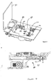
- FIG. 14 shows an exploded view of a cassette embodying the present invention.
- the cassette 2 comprises a first part 202 and a second part 204.
- the first part 202 and the second 204 define the housing 4 of the cassette.
- the cassette is arranged to house the supply of image receiving medium 6.
- the image receiving medium is provided on a spool 212.
- the spool 212 is arranged to spool engagement members 216 provided in the first half 202. Similar spool engagement members may be provided in the other half 204.
- These spool engagement members 216 are arranged to fit inside the spool 212 to position the spool 212 in the cassette.
- the spool engagement members 216 are positioned such that the image receiving medium spool is held in place but the spool is arranged to rotate about the spool engagement members 216.
- the cassette is also provided with the cover 28.
- the member 38 has the first locking projection 34 which is arranged to engage the opening 32 of the cover 28 to hold the cover in the closed position.
- the cassette also has an ink ribbon subassembly 214 which supports the ink ribbon take up spool 10 and the ink ribbon supply spool 12.
- Figure 6 shows a cassette receiving bay 40.
- an unlocking mechanism 50 for unlocking the cover.
- a perspective view of this mechanism is shown in Figure 4 whilst a cross-sectional view of this mechanism along line F-F is shown in Figure 5 .
- the unlocking mechanism 50 has a sliding part 52 which is arranged to move with respect to a housing 60.
- the sliding part 52 is configured to move in the direction of arrow C. This direction is parallel to the longitudinal length of the cover.
- the sliding part 52 moves in the same back and forth directions as the cover.
- the housing 60 is fixed in position in the tape printer and does not move.
- the sliding part 52 has an opening 53 through which an unlock member 54 projects.
- the unlock member 54 projects through the opening 53 and extends into the cassette receiving bay 40.
- This unlock member 54 is arranged to control the unlocking of the cover 28 in the cassette.
- the unlock member is biased to the position in which the unlock member projects through the opening 53. This biasing may be achieved as a result of the material which comprises the unlock member and/or as a result of the way in which the unlock member 54 is supported.
- the unlock member 54 may be separate from the main body 55 of the sliding part.
- the unlock member 54 is arranged to be mounted on the main body 55 of the sliding part.
- the unlock member 54 may be of the same or different material to the main body 55.
- Figure 7 shows the unlocking mechanism 50 and in particular the unlock member 54 extending to the cassette receiving bay 40.
- Figure 7 shows the cassette receiving bay before a cassette is inserted in the cassette receiving bay.
- the unlock member 54 deflects in the direction of arrow D so that the unlock member no longer extends into the cassette receiving bay.
- the sliding part 52 is in the initial position and the main body 55 of the sliding part has not moved.
- the area behind the unlocking mechanism 50 of the label printer has an opening 57 (shown in figure 8 ).
- This opening 57 is configured such that when the unlock member 54 is moved in the direction of arrow D, at least a part of the unlock member 54 can be accommodated in that opening 57.
- the unlock member 54 is such and/or is mounted so that the unlock member 54 is sufficiently flexible so that it can move in the direction of arrow D.
- FIG 8 This shows that the cassette is being inserted into the cassette receiving bay but has not been completely received in the cassette receiving bay.
- the cassette may be two thirds of the way in.
- the unlock member 54 is shown as having extended into the opening 57 of the label printer. This insertion of the cassette moves the unlock member 54 out of the cassette receiving bay so that the cassette 2 can be inserted in the cassette receiving bay. In this position, the unlock member 54 biases on the outer surface of the cover 28.
- the cassette is now partially shown.
- the size of opening 32 in the cover is such that the unlock member 54 can move first over such a distance that the unlock member does not move into opening 57 before it interacts with the side of the opening 32 to pull on the cover. This ensures that the unlock member 54 does not moves into opening 57 when it starts to pull on the cover.
- FIG 10 shows that the cover of the cassette is now in the open configuration, whilst the cassette is in the cassette receiving bay.
- the unlock member 54 is thus engaged with the opening 32 of the cover. Accordingly, when the sliding part 52 is moved in the direction of arrow E, the cover is also moved in the direction of arrow E. This movement moves the cover along the plane of the side 30, out of the cassette receiving bay into the label printer. The cover is moved in the direction away from the print area of the cassette and accordingly when in the open position a portion of the cassette cover will be received outside the cassette receiving bay, inside the label printer.
- the sliding part 52 is guided by the housing 60 which is sized to allow the sliding mechanism to move in the direction of arrow C.
- the housing 60 defines a pair of guide rails 62 which guide the movement of the sliding part 52.
- the sliding part has correspondingly shaped stepped parts 64 which engage the guide rails such that the sliding part is arranged to move in a defined path. Movement of the sliding part may be mechanically controlled or may be controlled by a motor.
- the movement of the sliding part is controlled by a cover 80 of the cassette receiving bay. As the cover 80 of the cassette receiving bay closes, the sliding part 52 is moved in the direction of arrow C. In one embodiment, the sliding part 52 is mechanically coupled to the cover 28 so that when the cover 80 of the cassette receiving bay is closed, the cover 28 of the cassette is open. Likewise when the cover 80 of the cassette receiving bay is open, the cover 28 of the cassette is closed.
- the sliding part moves against the force of a spring or other biasing member.
- the spring is located inside the label printer and is not in the cassette receiving bay. In one embodiment, the spring is located in label printer behind the sliding part and the housing, outside the cassette receiving bay. The spring is biased to urge the slider to the position shown in Figure 6 which corresponds to the cover of the cassette being in the closed position. Accordingly, when the cover 80 of the cassette receiving bay is opened, the cover 28 of the cassette will be urged to the closed position by the sliding part 52, the sliding part being moved by the biasing spring.
- movement of the cover 28 may be caused by a motor.
- the motor can be controlled that when the printer is ready for printing, the sliding member 52 is moved to the open position.
- FIG. 12a shows the under part of the cover 28.
- Part of the cover which is received in the label printer, outside the cassette receiving bay, when the cover 28 is in the open position.
- This part of the cover 28 is at the opposite end to the part of the cover 28 which covers the ink ribbon and image receiving medium.
- an EEPROM Electrical Erasable Programmable Read-Only Memory
- the EEPROM is located on a PCB (printed circuit board) 71 which is heat staked to the inside of the cover 28.
- This EEPROM is able to store information about the printing cassette which can be used to control parameters of the label printer.
- these parameters comprise one or more of:
- the label printer is provided with contacts 77 which contact corresponding contacts 73 on the PCB 71 on which the EEPROM 70 is mounted to allow the EEPROM to be read.
- a series of contacts 77 are provided on a PCB 79 in the label printer.
- the contacts 73 on the cover are arranged to be in contact with the contacts 77 of the label printer.
- the underside of the cover includes a rib 160 which defines the maximum distance that the cover can be moved in the direction of opening. This rib extends in the width direction of the cassette. Once the locking projection 34 is lifted out of opening 32 and the cover is moved, the locking projection 34 is biasing on the inside of the cover.
- the rib 160 on the inside of the cover interacts with the locking projection 34 when the cover is in the maximum opened position.
- the inside of the cover also has a pair of parallel longitudinal guide rails 75 which guide the movement of the locking projection 34 to thereby guide the movement of the cover.
- an EEPROM has been used.
- other suitable method of providing information to be used are : an RF (Radio frequency) tag, a barcode, a pattern of contacts which provides information for example in the form of a binary code.
- the label printer is configured such that printing is prevented unless the cover is in the correct open position.
- the position of the cover 28 itself may be detected or in an alternative embodiment of the present invention, the determination that the cover is in the correct open position is made when the detector of the label printer connects to the EEPROM 70 or the like. In this way, additional circuitry is avoided.
- the position of the cover may be determined by means of a light source and detector having the path there between interrupted by the cover, contacts provided on the cover which, when the cover is open, close a circuit, by the cover activating a switch or with any other suitable mechanism.
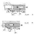
- the movement of the cover 28 is also arranged to control a platen roller lock 400 as will be described with reference to Figures 15 to 18 .
- the platen roller lock 400 is arranged to have a first end 402.
- the first end 402 is arranged to be actuated by the cover 28.
- the cover 28 is in the closed position, the first end 402 of the platen roller lock 400 is in a position which causes the platen roller lock 400 to prevent the platen from being moved towards the print head.
- the platen roller locking member 400 is mounted to pivot about a pivot point 404.
- the pivot point 404 is between the first end 402 and a second end 406 of the platen roller locking member
- Figure 15 shows the first end 402 in the position such that the platen roller is prevented from moving by the second end 406.
- the first end 402 is arranged to extend into the part of the label printer which receives the cover when the cover is in the open position.
- the second end 406 engages a stop 405 of a platen roller support 408. Because the second end 406 engages against the stop 405, the platen roller is prevented from moving towards the print head.
- FIG 16 and 17 shows the cover 28 in the open position.
- the cover 28 has moved the first end 402 in the direction of arrow M, away from the space which accommodates the cover when in the open position.
- the second end 406 is moved in the direction of arrow N, that is in an opposite direction to arrow M, about the pivot point 404.
- the second end 406 When the cover has moved the first end 402 in the direction of arrow M, the second end 406 is moved to the position as shown in Figures 16 and 17 The second end 406 is moved in the direction of arrow N out of contact with the stop 405 of the platen roller support. Accordingly, the platen is then able to move towards the print head. Thus, as the cover is opened the platen can be moved towards the print head. When the cover is closed or there is no cassette present, the platen roller support 408 is prevented from moving by the stop 405.
- the platen locking member 400 is biased to the position in which the platen roller support 400 is prevented from moving.
- FIG. 13 shows basic circuitry for controlling the label printer.
- a microprocessor chip 300 In practice there may be more than one chip. This chip is shown diagrammatically as having read-only memory 302, a processing part 301 and random access memory capacity indicated diagrammatically by RAM 304. However, this is by way of example and different memory and processing arrangements may be used in alternative embodiments.
- the microprocessor chip or chips are arranged to receive label data from a data input device such as a keyboard. Alternatively or additionally, the data input device may comprise a touch screen and/or a data port (e.g. a USB port) arranged to receive data from a PC or the like.
- a data input device such as a keyboard.
- the data input device may comprise a touch screen and/or a data port (e.g. a USB port) arranged to receive data from a PC or the like.
- the microprocessor chip or chips 300 are arranged to output data to drive a display 310 via a display driver 309. That display may display a label to be printed (or a part thereof) and/or a message for the user. This display may for example be a LCD display or a touch screen.
- the display driving capacity may be provided as part of the microprocessor chip or chips.
- the microprocessor chip or chips are also arranged to output data to drive the print head 322 so that label data is printed onto the image receiving medium to form a label.
- the microprocessor chip or chips 300 may also control a motor 307 for driving the image receiving medium.
- microprocessor chip or chips may also control a cutting mechanism 358 to allow a length of tape to be cut off.
- a manual cutter may alternatively be provided.
- the label printer is a stand-alone printer.
- This stand-alone printer may operate independently or may be connected to receive data from a PC.
- the label printer may be a PC printer and as such, the keyboard and display may be omitted as the data may be input and displayed on the PC. The PC then acts as an input device for the printer.
Description
- The present invention relates to a cassette for use in a label printer.
- A label printer generally comprises a print head which is controlled to print onto an image receiving tape medium or onto a consumable in the form of a continuous backing sheet on which pre-cut labels are provided. The image receiving medium is generally provided in the cassette which is received in a cassette receiving bay of the label printer.
- Some cassettes are arranged such that the image receiving medium is drawn out of the cassette to a print zone defined between a print head and a platen of the label printer. Printing on the image receiving medium occurs at the print zone. In some cassettes, a print area is provided for accommodating at least part of the print head or the platen. Some cassettes may have an opening which allows the image receiving medium to exit the cassette housing on one side of the print zone, extend through the print zone and then to exit the cassette completely on the other side of the print zone.
- Some cassettes also contain an ink ribbon. The ink ribbon thus may also pass across this print zone, following a similar path to the image receiving medium.
- When the image receiving medium and ink ribbon, if present, pass across the area of the cassette defined for the print zone, foreign matter such as dust and dirt can contact, stick to and damage either or both of the image receiving medium and ink ribbon. Subsequent printing using the ink ribbon and image receiving medium may therefore be of poor quality.
-
JP2002-127533 -
JP61-164872 -
GB2311765 - According to an aspect there is provided label printer cassette as defined in claim 1.
- Some embodiments of the present invention will now be described, by way of example only, with reference to the accompanying Drawings in which:
-
Figure 1 shows a cross-section of a cassette embodying according to one embodiment of the present invention; -
Figure 2 shows a perspective view of the cassette ofFigure 1 ; -
Figure 3 shows part of the cassette ofFigure 1 in more detail; -
Figure 4 shows a perspective view of an unlocking mechanism in a label printer for unlocking a cover of the cassette ofFigure 1 ; -
Figure 5 shows a cross-sectional view of the unlocking mechanism ofFigure 4 , along line F-F ofFigure 4 ; -
Figure 6 shows a perspective view of a cassette receiving bay of the label printer; -
Figure 7 shows a cross section of part of the label printer showing the unlocking mechanism before the cassette ofFigure 1 is inserted into the cassette receiving bay; -
Figure 8 shows a cross-section view of the part of the label printer shown inFigure 7 and the cassette ofFigure 1 , as the cassette is inserted; -
Figure 9 shows a cross-section view of the part of the label printer shown inFigure 7 and the cassette ofFigure 1 , with the cover of the cassette in an unlocked configuration; -
Figure 10 shows a cross-section view of the part of the label printer shown inFigure 7 and the cassette ofFigure 1 , with the cover of the cassette in an open position; -
Figure 11 shows a perspective view of the cassette ofFigure 1 , with the cover in an open position; -
Figure 12a shows the underside of the cover ; -
Figure 12b shows the part of the printer which interacts with the EEPROM of the cover; -
Figure 13 shows schematically parts of a label printer; -
Figure 14 shows an exploded view of a cassette; -
Figure 15 shows a platen lock member and the cover where the platen lock member is in a lock position where the platen roller is locked; -
Figure 16 shows the platen lock member ofFigure 15 in an unlock position such that the platen can move; -
Figure 17 shows a perspective view of the underside of the cassette receiving bay showing the platen lock member in the unlock position; and -
Figure 18 shows in detail the interaction between the platen lock member with the platen support member in the lock position. - In the Figures, like reference numerals indicate like parts.
- The cassette shown in the Figures is arranged to house one or more supplies of print medium. The print medium may be an ink ribbon and/or may be an image receiving medium. An image receiving medium may be in the form of an image receiving tape having an upper image receiving layer for receiving an image and a removable backing layer secured to the upper image receiving layer by a layer of adhesive such that after an image has been printed the backing layer can be removed and the image receiving layer can be stuck to a surface. This image receiving tape may be a continuous supply. Accordingly, the cassette may be used with a label printer which includes a cutter for cutting off a length of image receiving tape after the image has been printed.
- Alternatively, the image receiving medium may comprise a continuous backing layer whilst an image receiving layer is in the form of pre-cut labels. In this example, the label can be printed and then peeled off from the backing layer. Alternatively, the labels may be connected together with no backing layer. The labels may be separated by lines indicating where a user should cut or lines of weakness such as perforations.
- As mentioned, the cassette may hold an image receiving medium or an ink ribbon. In some embodiments, the cassette may house and image receiving medium and an ink ribbon.
- Some cassettes may be used with a thermal label printer where an image is generated by the activation of a thermal printhead against the ink ribbon such that ink from the ink ribbon is transferred onto the image receiving medium at a print zone.
- It should be appreciated that in some embodiments of the present invention, where the cassette just houses an image receiving medium, that image receiving medium may be in the form of a direct thermal image receiving medium. A direct thermal image receiving medium is such that an image can be created directly onto or within the direct thermal image receiving medium by a thermal printhead, without the requirement of an ink ribbon.
- It should be appreciated that in an alternative embodiment, the cassette may only house an image receiving medium. An ink ribbon may be housed in a separate cassette.
- Alternative embodiments of the invention may have different image receiving medium structures. For example a protective layer may in some embodiments be applied to the printed surface after printing. In other embodiments of the invention, a protective layer may be provided on the image receiving surface and printing occurs through the protective layer. In yet another embodiment, an image is applied to a surface of an image receiving medium and then the image receiving medium is adhered to the backing layer, with the printed image being on the side of the image receiving medium being adhered to the backing layer. In some embodiments, there may be not backing layer. These embodiments may have a layer of adhesive. In alternative embodiments, there may not be any adhesive. These are just some examples of the possible structure of the image receiving medium and other structures are of course possible.
- In some embodiments of the invention, a particular label printer may be arranged to receive a range of different cassettes housing different image receiving mediums and/or ink ribbons. The printing media may be different in type and/or width. The cassettes may differ in their thickness depending on the size of the printing media accommodated therein.
- Mention has been made of the use of a thermal print head. It should be appreciated that alternative embodiments may use different printing technologies such as ink jet or any other suitable printing technique.
- Some cassettes and label printers embodying the present invention will now be described with reference to the accompanying Figures.
- Referring first particularly to
Figure 1 , thecassette 2 has ahousing 4. Thehousing 4 is arranged to contain a supply ofimage receiving medium 6 and anink ribbon 8. Theink ribbon 8 is provided on an inkribbon supply spool 12 and is, when used, taken up by the ink ribbon take-upspool 10. When the cassette is inserted into acassette bay 40, theimage receiving medium 6 andink ribbon 8 are arranged to pass in overlap past aprint head 22 which acts against arotatable platen 24. Theprint head 22 andplaten 24 can be seen fromFigure 6 . - In this embodiment, the
print head 22 is fixed in position and themoveable platen 24 is able not only to rotate about its axis but also to move between a non-printing position in which the platen is spaced apart from the print head and a printing position in which theplaten 24 acts against theprint head 22. It should be appreciated that in alternative embodiments of the present invention, the platen may be fixed into position, for example only able to rotate about its axis and the print head moves between the printing and non-printing positions. In a further alternative embodiment, both the print head and the platen may be arranged to be moved one towards the other so as to, for example move from a non-printing position to a printing position. - The
print head 22 is arranged, when the cassette is in the cassette receiving bay to be accommodated in aprint area 16 defined in the cassette. This print area can be seen fromFigures 1 and 2 . The print head is arranged to be accommodated in theprint area 16 with theimage receiving medium 6 andink ribbon 8 passing in overlap between theprint head 22 and theplaten 24. A print zone is thus provided between theprint head 22 and theplaten 24. - The
ink ribbon 8 is taken from the inkribbon supply spool 12 and after passing through the print zone is taken up by the ink ribbon take-upspool 10. As can be seen fromFigure 2 , the housing of the cassette has afirst opening 20 aligned with the ink ribbon supply spool. This first opening is provided on the side of the cassette which faces the cassette receiving bay and is arranged to receive afirst member 25 provided in the cassette receiving bay. The underside of the cassette has asecond opening 18 aligned with the ink ribbon take up spool. Thissecond opening 18 is arranged to receive asecond member 26 provided in the cassette receiving bay. These first andsecond members ribbon supply spool 12 and the ink ribbon take-upspool 10. One or both of theengagement members - As shown in
Figure 2 , acover 28 is provided on acover side 30 of thecassette 2. Thecover side 30 is one of the four sides which extend between afirst surface 31 and asecond surface 29 and can be fromFigure 14 . These four sides are parallel to the respective axes defined by each of the first andsecond members medium supply 6 and theink ribbon supply 12 rotate. In other words, the four sides are perpendicular to the first and second surfaces. Thecover side 30 is the side which has theopening 33 through which the image receiving medium and the ink ribbon exits the cassette. Thecover side 30 is the side which generally defines the print zone and which defines (with the cover 28) theexit 35 of the cassette. Thecover 28 is arranged to move along the plane ofside 30 between the closed position, which is shown inFigure 2 and the open position which is shown inFigure 11 . The cover is thus arranged to move in the plane ofside 30, in the direction of arrow B. Thecover 28 is arranged to move back and forth along the length direction of the side. In some embodiments, the cover may move in the width direction of the slide, have a rotational movement, or move in a combination of any of these directions. Whencover 28 is in the closed position, the image receiving medium and ink ribbon adjacent to theprint area 16 are covered and hence protected from the exposure to foreign matter. When the cover is open, as shown inFigure 11 , the image receiving medium and ink ribbon are exposed so that the platen can contact the image receiving medium, when acting against the print head and printing can be performed. - The movement of the cover will now be described in more detail. Reference is made to
Figure 3 which shows part of the cassette ofFigure 1 in greater detail. Thecover 28 has anopening 32. Theopening 32 is arranged, when the cover is in the closed position to engage a lockingprojection 34 of the cassette. Theprojection 34 engages, that is received in, theopening 32 in the cover and thus prevents the cover from being opened when the cassette is outside the label printer. Theprojection 34 is provided on a generallyplanar member 38 which extends generally parallel to thecover 28. Thismember 38 is made of a resilient material such that it is normally biased to the position shown inFigure 3 . Alternatively or additionally themember 38 itself may be supported or mounted such that theprojection 34 is biased to the position shown inFigure 3 . In this scenario, themember 38 may be relatively rigid. Alternatively or additionally, the projection itself may be of a resilient material. - Reference is now made to
Figure 14 which shows an exploded view of a cassette embodying the present invention. Thecassette 2 comprises afirst part 202 and asecond part 204. Thefirst part 202 and the second 204 define thehousing 4 of the cassette. - The cassette is arranged to house the supply of
image receiving medium 6. As can be seen, the image receiving medium is provided on aspool 212. Thespool 212 is arranged tospool engagement members 216 provided in thefirst half 202. Similar spool engagement members may be provided in theother half 204. Thesespool engagement members 216 are arranged to fit inside thespool 212 to position thespool 212 in the cassette. Thespool engagement members 216 are positioned such that the image receiving medium spool is held in place but the spool is arranged to rotate about thespool engagement members 216. - The cassette is also provided with the
cover 28. Themember 38 has thefirst locking projection 34 which is arranged to engage theopening 32 of thecover 28 to hold the cover in the closed position. The cassette also has anink ribbon subassembly 214 which supports the ink ribbon take upspool 10 and the inkribbon supply spool 12. - Reference is now made to
Figures 4, 5 and6 which show parts of the label printer which are arranged to cause the unlocking of the cover member. In particular,Figure 6 shows acassette receiving bay 40. On theside 42 of the cassette receiving bay, which faces the cover, is an unlockingmechanism 50 for unlocking the cover. A perspective view of this mechanism is shown inFigure 4 whilst a cross-sectional view of this mechanism along line F-F is shown inFigure 5 . The unlockingmechanism 50 has a slidingpart 52 which is arranged to move with respect to ahousing 60. The slidingpart 52 is configured to move in the direction of arrow C. This direction is parallel to the longitudinal length of the cover. The slidingpart 52 moves in the same back and forth directions as the cover. Thehousing 60 is fixed in position in the tape printer and does not move. - The sliding
part 52 has anopening 53 through which anunlock member 54 projects. When the unlockingmechanism 50 is in thecassette receiving bay 40, theunlock member 54 projects through theopening 53 and extends into thecassette receiving bay 40. Thisunlock member 54 is arranged to control the unlocking of thecover 28 in the cassette. The unlock member is biased to the position in which the unlock member projects through theopening 53. This biasing may be achieved as a result of the material which comprises the unlock member and/or as a result of the way in which theunlock member 54 is supported. Theunlock member 54 may be separate from the main body 55 of the sliding part. Theunlock member 54 is arranged to be mounted on the main body 55 of the sliding part. Theunlock member 54 may be of the same or different material to the main body 55. - The interaction of the cover of the cassette and the cassette receiving bay of the label printer will now be described in more detail.
- Reference is now made to
Figure 7 which shows the unlockingmechanism 50 and in particular theunlock member 54 extending to thecassette receiving bay 40.Figure 7 shows the cassette receiving bay before a cassette is inserted in the cassette receiving bay. When inserting the cassette, theunlock member 54 deflects in the direction of arrow D so that the unlock member no longer extends into the cassette receiving bay. The slidingpart 52 is in the initial position and the main body 55 of the sliding part has not moved. The area behind the unlockingmechanism 50 of the label printer has an opening 57 (shown infigure 8 ). Thisopening 57 is configured such that when theunlock member 54 is moved in the direction of arrow D, at least a part of theunlock member 54 can be accommodated in thatopening 57. Theunlock member 54 is such and/or is mounted so that theunlock member 54 is sufficiently flexible so that it can move in the direction of arrow D. - Reference is now made to
Figure 8 . This shows that the cassette is being inserted into the cassette receiving bay but has not been completely received in the cassette receiving bay. For example, the cassette may be two thirds of the way in. Theunlock member 54 is shown as having extended into theopening 57 of the label printer. This insertion of the cassette moves theunlock member 54 out of the cassette receiving bay so that thecassette 2 can be inserted in the cassette receiving bay. In this position, theunlock member 54 biases on the outer surface of thecover 28. In contrast to the figure shown inFigure 7 , the cassette is now partially shown. - Reference is now made to
Figure 9 , the cassette is now completely received in the cassette receiving bay. Theunlock member 54 has moved back to the position in which theunlock member 54 extends into the cassette receiving bay. However, because the cassette is now in the cassette receiving bay, theunlock member 54 is aligned with theopening 32 of thecover 28. Theunlock member 54 is thus arranged to extend through theopening 32 to move lockingprojection 34 in a direction towards the inside of the cassette and away from the cover. The lockingprojection 34 no longer engages the opening of thecover 32 and the cover can now be moved. However, theunlock member 54 is now engaged with thecover 32 such that if the slidingpart 52 is moved, thecover 28 will move with the sliding part. - Before starting to pull with
unlock member 54 on the cover inopening 32, it has to be ensured that unlockmember 54 does not move into theopening 57. Therefore, the size of opening 32 in the cover is such that theunlock member 54 can move first over such a distance that the unlock member does not move intoopening 57 before it interacts with the side of theopening 32 to pull on the cover. This ensures that theunlock member 54 does not moves intoopening 57 when it starts to pull on the cover. - Reference is made to
Figure 10 which shows that the cover of the cassette is now in the open configuration, whilst the cassette is in the cassette receiving bay. Theunlock member 54 is thus engaged with theopening 32 of the cover. Accordingly, when the slidingpart 52 is moved in the direction of arrow E, the cover is also moved in the direction of arrow E. This movement moves the cover along the plane of theside 30, out of the cassette receiving bay into the label printer. The cover is moved in the direction away from the print area of the cassette and accordingly when in the open position a portion of the cassette cover will be received outside the cassette receiving bay, inside the label printer. - It should be appreciated that the sliding
part 52 is guided by thehousing 60 which is sized to allow the sliding mechanism to move in the direction of arrow C. Thehousing 60 defines a pair ofguide rails 62 which guide the movement of the slidingpart 52. The sliding part has correspondingly shaped steppedparts 64 which engage the guide rails such that the sliding part is arranged to move in a defined path. Movement of the sliding part may be mechanically controlled or may be controlled by a motor. - In one embodiment, the movement of the sliding part is controlled by a cover 80 of the cassette receiving bay. As the cover 80 of the cassette receiving bay closes, the sliding
part 52 is moved in the direction of arrow C. In one embodiment, the slidingpart 52 is mechanically coupled to thecover 28 so that when the cover 80 of the cassette receiving bay is closed, thecover 28 of the cassette is open. Likewise when the cover 80 of the cassette receiving bay is open, thecover 28 of the cassette is closed. - Alternatively or additionally the sliding part moves against the force of a spring or other biasing member. The spring is located inside the label printer and is not in the cassette receiving bay. In one embodiment, the spring is located in label printer behind the sliding part and the housing, outside the cassette receiving bay. The spring is biased to urge the slider to the position shown in
Figure 6 which corresponds to the cover of the cassette being in the closed position. Accordingly, when the cover 80 of the cassette receiving bay is opened, thecover 28 of the cassette will be urged to the closed position by the slidingpart 52, the sliding part being moved by the biasing spring. - In an alternative embodiment of the present invention, movement of the
cover 28 may be caused by a motor. The motor can be controlled that when the printer is ready for printing, the slidingmember 52 is moved to the open position. - Reference is made to
Figure 12a which shows the under part of thecover 28. Part of the cover which is received in the label printer, outside the cassette receiving bay, when thecover 28 is in the open position. This part of thecover 28 is at the opposite end to the part of thecover 28 which covers the ink ribbon and image receiving medium. In the embodiment shown, an EEPROM (Electrically Erasable Programmable Read-Only Memory) 70 is provided. The EEPROM is located on a PCB (printed circuit board) 71 which is heat staked to the inside of thecover 28. This EEPROM is able to store information about the printing cassette which can be used to control parameters of the label printer. By way of example only, these parameters comprise one or more of: - Size information on the image receiving medium; width of the label medium;
- where the image receiving medium is in the form of discrete labels,
- information associated with the discrete labels; information on the colour of the image receiving medium; information on the material of the image receiving medium; ink ribbon colour; information controlling the print head energy; information controlling print head pressure; template information associated with the image receiving medium; amount of image receiving medium used; amount of image receiving medium remaining: or any other suitable information.
- To read the
EEPROM 70, the label printer is provided withcontacts 77 which contact corresponding contacts 73 on the PCB 71 on which theEEPROM 70 is mounted to allow the EEPROM to be read. As can be seen fromFigure 12b , a series ofcontacts 77 are provided on aPCB 79 in the label printer. When the cover is in the open position, the contacts 73 on the cover are arranged to be in contact with thecontacts 77 of the label printer. - As can be seen from
Figure 12a , the underside of the cover includes arib 160 which defines the maximum distance that the cover can be moved in the direction of opening. This rib extends in the width direction of the cassette. Once the lockingprojection 34 is lifted out of opening 32 and the cover is moved, the lockingprojection 34 is biasing on the inside of the cover. Therib 160 on the inside of the cover interacts with the lockingprojection 34 when the cover is in the maximum opened position. The inside of the cover also has a pair of parallellongitudinal guide rails 75 which guide the movement of the lockingprojection 34 to thereby guide the movement of the cover. - It should be appreciated that in this embodiment an EEPROM has been used. However, other suitable method of providing information to be used are : an RF (Radio frequency) tag, a barcode, a pattern of contacts which provides information for example in the form of a binary code.
- In one embodiment of the present invention, the label printer is configured such that printing is prevented unless the cover is in the correct open position. In order to verify this, the position of the
cover 28 itself may be detected or in an alternative embodiment of the present invention, the determination that the cover is in the correct open position is made when the detector of the label printer connects to theEEPROM 70 or the like. In this way, additional circuitry is avoided. - The position of the cover may be determined by means of a light source and detector having the path there between interrupted by the cover, contacts provided on the cover which, when the cover is open, close a circuit, by the cover activating a switch or with any other suitable mechanism.
- The movement of the
cover 28 is also arranged to control aplaten roller lock 400 as will be described with reference toFigures 15 to 18 . Theplaten roller lock 400 is arranged to have afirst end 402. Thefirst end 402 is arranged to be actuated by thecover 28. When thecover 28 is in the closed position, thefirst end 402 of theplaten roller lock 400 is in a position which causes theplaten roller lock 400 to prevent the platen from being moved towards the print head. The platenroller locking member 400 is mounted to pivot about apivot point 404. Thepivot point 404 is between thefirst end 402 and asecond end 406 of the platen roller locking member -
Figure 15 shows thefirst end 402 in the position such that the platen roller is prevented from moving by thesecond end 406. Thefirst end 402 is arranged to extend into the part of the label printer which receives the cover when the cover is in the open position. - Initially, as shown in
Figure 18 andFigure 15 , thesecond end 406 engages a stop 405 of aplaten roller support 408. Because thesecond end 406 engages against the stop 405, the platen roller is prevented from moving towards the print head. - Reference is made to
Figure 16 and17 which shows thecover 28 in the open position. As can be seen, thecover 28 has moved thefirst end 402 in the direction of arrow M, away from the space which accommodates the cover when in the open position. When thecover 28 moves thefirst end 402 in the direction of arrow M, thesecond end 406 is moved in the direction of arrow N, that is in an opposite direction to arrow M, about thepivot point 404. - When the cover has moved the
first end 402 in the direction of arrow M, thesecond end 406 is moved to the position as shown inFigures 16 and17 Thesecond end 406 is moved in the direction of arrow N out of contact with the stop 405 of the platen roller support. Accordingly, the platen is then able to move towards the print head. Thus, as the cover is opened the platen can be moved towards the print head. When the cover is closed or there is no cassette present, theplaten roller support 408 is prevented from moving by the stop 405. - The
platen locking member 400 is biased to the position in which theplaten roller support 400 is prevented from moving. - Reference is made to
Figure 13 which shows basic circuitry for controlling the label printer. There is a microprocessor chip 300. In practice there may be more than one chip. This chip is shown diagrammatically as having read-only memory 302, aprocessing part 301 and random access memory capacity indicated diagrammatically by RAM 304. However, this is by way of example and different memory and processing arrangements may be used in alternative embodiments. The microprocessor chip or chips are arranged to receive label data from a data input device such as a keyboard. Alternatively or additionally, the data input device may comprise a touch screen and/or a data port (e.g. a USB port) arranged to receive data from a PC or the like. - The microprocessor chip or chips 300 are arranged to output data to drive a
display 310 via a display driver 309. That display may display a label to be printed (or a part thereof) and/or a message for the user. This display may for example be a LCD display or a touch screen. The display driving capacity may be provided as part of the microprocessor chip or chips. - The microprocessor chip or chips are also arranged to output data to drive the
print head 322 so that label data is printed onto the image receiving medium to form a label. - The microprocessor chip or chips 300 may also control a motor 307 for driving the image receiving medium.
- Finally, the microprocessor chip or chips may also control a
cutting mechanism 358 to allow a length of tape to be cut off. In alternative embodiments of the present invention, a manual cutter may alternatively be provided. - In one embodiment of the present invention, the label printer is a stand-alone printer. This stand-alone printer may operate independently or may be connected to receive data from a PC. In alternative embodiments of the present invention, the label printer may be a PC printer and as such, the keyboard and display may be omitted as the data may be input and displayed on the PC. The PC then acts as an input device for the printer.
Claims (15)
- A label printer cassette (2) comprising:a supply of print medium (6, 8);a housing (4) for housing said print medium (6, 8), said housing (4) having first and second surfaces (29, 31) and at least one side (30) extending between said first and second surfaces (29, 31); anda cover (28) provided on one (30) of said sides movable along the length of the said one side (30) between a first position in which said print medium (6, 8) is exposed for printing and a second position in which said print medium (6, 8) is protected;characterised in that said cover (28) comprises cassette information providing means (70, 73) comprising at least one of; an EEPROM (70); at least one contact (73); a pattern of contacts (73); an RF tag; and a bar code.
- cassette as claimed in claim 1, wherein said cover comprises an opening, wherein said opening is configured such that in use, when said cassette is in a label printer, a moving means of said printer is received in said opening to move said cover from one of said first and second positions to the other of said first and second positions.
- A cassette as claimed in claims 1 or 2, wherein one of said cover (28) and said cassette (2) comprises an opening (32) and the other of said cover (28) and said cassette (2) comprises a projection (34), wherein said opening (32) and said projection (34) are engagable one with the other to lock the cover (28) in one of said first and second positions.
- A cassette as claimed in claim 3, wherein said projection (34) is configured to be moved between a first projection position, in which said projection (34) is engaged in said opening (32), and a second projection position, in which said projection (34) is unengaged from said opening (32) such that said cover (28) can be moved from said second position to said first position.
- A cassette as claimed in claim 4, wherein said opening (32) is configured such that an unlocking means of a printer is receivable in said opening (32) to move the projection (34) to the second projection position, such that said cover (32) is then movable from said second position to said first position.
- A cassette (2) as claimed in any preceding claim, wherein stop means (160) are provided on said cover (28) for preventing the cover (28) moving from the first position in a direction away from said second position.
- A cassette (2) as claimed in claim 6 when appended to claim 3, wherein said projection (34) is configured to act against the stop means (160) to prevent the cover (28) being moved from the first position in a direction away from said second position.
- A cassette (2) as claimed in any preceding claim, wherein said cover (28) comprises a pair of guides (75) for guiding the movement of the cover (28) between said first and second positions.
- A cassette (2) as claimed in claim 8, wherein the cassette (2) further comprises a guiding means, wherein the guiding means is configured to be guided between said first and second positions between said pair of guides (75).
- A cassette (2) as claimed in claim 6 when appended to claim 3, wherein said projection (34) is configured to be guided between said first and second positions between said pair of guides (75).
- A cassette as claimed in any preceding claim, wherein said cover is configured to control a platen lock member of a label printer, in use.
- A cassette as claimed in claim 11 wherein said cover is configured to control the platen lock member to be in a locked position when in the second position and to be unlocked when in the first position.
- A cassette as claimed in any preceding claim, wherein said cover comprises at least one contact which when said cassette is in said label printer and the cover is in the second position is configured to complete a detection circuit in said label printer.
- A cassette (2) as claimed in claim 1, wherein said cassette information providing means (70, 73) is provided on an inner side of said cover (28) such that when said cover (28) is in said second position, said cassette information providing means (70, 73) are protected and when said cover (28) is in the first position said cassette information providing means (70, 73) are exposed.
- A cassette as claimed in any preceding claim, wherein said cassette information providing means (70, 73) are configured to provide one or more of the following information; size information on an image receiving medium; width of an image receiving medium; where an image receiving medium is in the form of discrete labels, information associated with the discrete labels; information on a colour of a image receiving medium; information on a material of an image receiving medium; ink ribbon colour; information controlling the print head energy; information controlling print head pressure; template information associated with image receiving medium; amount of image receiving medium used; amount of image receiving medium remaining: and cassette presence information.
Priority Applications (1)
| Application Number | Priority Date | Filing Date | Title |
|---|---|---|---|
| PL10161329T PL2246197T3 (en) | 2009-04-28 | 2010-04-28 | Cassette for use in a label printer |
Applications Claiming Priority (2)
| Application Number | Priority Date | Filing Date | Title |
|---|---|---|---|
| GBGB0907281.0A GB0907281D0 (en) | 2009-04-28 | 2009-04-28 | Cassettes |
| GB0907280A GB0907280D0 (en) | 2009-04-28 | 2009-04-28 | Cassette for use in a tape printer |
Publications (2)
| Publication Number | Publication Date |
|---|---|
| EP2246197A1 EP2246197A1 (en) | 2010-11-03 |
| EP2246197B1 true EP2246197B1 (en) | 2012-08-22 |
Family
ID=42225029
Family Applications (3)
| Application Number | Title | Priority Date | Filing Date |
|---|---|---|---|
| EP10718561.3A Active EP2416966B1 (en) | 2009-04-28 | 2010-04-28 | CASSETTE FOR USE IN A LABEL PRINTER, label printer and combination thereof |
| EP10161329A Not-in-force EP2246197B1 (en) | 2009-04-28 | 2010-04-28 | Cassette for use in a label printer |
| EP15173942.2A Active EP2974874B1 (en) | 2009-04-28 | 2010-04-28 | Cassette for use in a label printer |
Family Applications Before (1)
| Application Number | Title | Priority Date | Filing Date |
|---|---|---|---|
| EP10718561.3A Active EP2416966B1 (en) | 2009-04-28 | 2010-04-28 | CASSETTE FOR USE IN A LABEL PRINTER, label printer and combination thereof |
Family Applications After (1)
| Application Number | Title | Priority Date | Filing Date |
|---|---|---|---|
| EP15173942.2A Active EP2974874B1 (en) | 2009-04-28 | 2010-04-28 | Cassette for use in a label printer |
Country Status (8)
| Country | Link |
|---|---|
| US (3) | US8939665B2 (en) |
| EP (3) | EP2416966B1 (en) |
| JP (3) | JP5584286B2 (en) |
| CN (3) | CN102458867B (en) |
| AU (2) | AU2010243573B2 (en) |
| ES (1) | ES2390262T3 (en) |
| PL (1) | PL2246197T3 (en) |
| WO (4) | WO2010125128A1 (en) |
Cited By (1)
| Publication number | Priority date | Publication date | Assignee | Title |
|---|---|---|---|---|
| US8469615B2 (en) | 2009-04-28 | 2013-06-25 | Dymo | Cassette for use in a label printer |
Families Citing this family (34)
| Publication number | Priority date | Publication date | Assignee | Title |
|---|---|---|---|---|
| EP2752300B1 (en) | 2008-12-25 | 2021-06-09 | Brother Kogyo Kabushiki Kaisha | Tape cassette and tape printer |
| EP3854595A1 (en) | 2008-12-25 | 2021-07-28 | Brother Kogyo Kabushiki Kaisha | Tape cassette and tape printer |
| EP3106314B1 (en) | 2009-03-31 | 2022-04-27 | Brother Kogyo Kabushiki Kaisha | Tape cassette and tape printer |
| JP5136503B2 (en) | 2009-03-31 | 2013-02-06 | ブラザー工業株式会社 | Tape cassette |
| CN104442030B (en) | 2009-03-31 | 2017-04-12 | 兄弟工业株式会社 | Tape cassette |
| AU2010231426B2 (en) | 2009-03-31 | 2015-09-03 | Brother Kogyo Kabushiki Kaisha | Tape cassette and tape printer |
| CN105398230B (en) | 2009-03-31 | 2017-10-13 | 兄弟工业株式会社 | Tape drum |
| EP2448762B1 (en) | 2009-06-30 | 2013-09-18 | Brother Kogyo Kabushiki Kaisha | Tape cassette and tape printer |
| EP2514600B1 (en) | 2009-12-16 | 2015-01-21 | Brother Kogyo Kabushiki Kaisha | Tape cassette |
| CN102481794B (en) | 2009-12-28 | 2014-12-10 | 兄弟工业株式会社 | Tape cassette |
| US20110229238A1 (en) * | 2010-03-18 | 2011-09-22 | Seiko Epson Corporation | Tape Cartridge |
| GB201007070D0 (en) * | 2010-04-28 | 2010-06-09 | Dymo Nv | Cassette for use in a label printer |
| GB201007081D0 (en) * | 2010-04-28 | 2010-06-09 | Dymo Nv | Cassette for use in a label printer |
| GB201007087D0 (en) * | 2010-04-28 | 2010-06-09 | Dymo Nv | Cassette for use in a label printer |
| GB201007082D0 (en) * | 2010-04-28 | 2010-06-09 | Dymo Nv | Cassette for use in a label printer |
| JP1459154S (en) * | 2010-04-28 | 2015-12-28 | ||
| JP5857633B2 (en) * | 2011-10-31 | 2016-02-10 | ブラザー工業株式会社 | Tape printer |
| CN202573313U (en) * | 2012-04-18 | 2012-12-05 | 珠海天威飞马打印耗材有限公司 | Printing template |
| GB201304743D0 (en) * | 2013-03-15 | 2013-05-01 | Dymo Nv | Label Printer |
| JP6381941B2 (en) * | 2014-03-24 | 2018-08-29 | セイコーエプソン株式会社 | Tape cartridge |
| JP6134283B2 (en) | 2014-03-24 | 2017-05-24 | セイコーエプソン株式会社 | Tape cartridge |
| EP3150530B1 (en) * | 2015-09-29 | 2020-01-08 | Canon Kabushiki Kaisha | Reception apparatus |
| JP6737676B2 (en) * | 2016-09-30 | 2020-08-12 | 日本電産サンキョー株式会社 | Card processing equipment |
| JP6880643B2 (en) * | 2016-10-19 | 2021-06-02 | カシオ計算機株式会社 | Printing equipment |
| US10906327B2 (en) * | 2017-09-26 | 2021-02-02 | Sato Holdings Kabushiki Kaisha | Printer |
| JP7121025B2 (en) | 2017-09-26 | 2022-08-17 | サトーホールディングス株式会社 | printer |
| JP2019089253A (en) * | 2017-11-14 | 2019-06-13 | 株式会社東芝 | Binding mechanism and binding unit |
| WO2019230011A1 (en) | 2018-06-01 | 2019-12-05 | サトーホールディングス株式会社 | Printer |
| JP7213680B2 (en) * | 2018-12-26 | 2023-01-27 | セイコーエプソン株式会社 | cartridge |
| JP7208785B2 (en) * | 2018-12-26 | 2023-01-19 | セイコーエプソン株式会社 | cartridge |
| US11241896B2 (en) * | 2019-06-19 | 2022-02-08 | Seiko Epson Corporation | Housing case and tape ribbon set |
| JP7279537B2 (en) * | 2019-06-19 | 2023-05-23 | セイコーエプソン株式会社 | Mounting table and tape printing system |
| JP7287840B2 (en) * | 2019-06-19 | 2023-06-06 | セイコーエプソン株式会社 | Container and tape printing system |
| JP7439596B2 (en) * | 2020-03-19 | 2024-02-28 | セイコーエプソン株式会社 | board cartridge |
Family Cites Families (86)
| Publication number | Priority date | Publication date | Assignee | Title |
|---|---|---|---|---|
| GB1406084A (en) | 1971-09-17 | 1975-09-10 | Sony Corp | Cartridge for use in magnetic recording and or reproducing apparatus |
| DE3405164A1 (en) | 1984-02-14 | 1985-08-22 | Olympia Werke Ag, 2940 Wilhelmshaven | Ink supply container for ink jet printers |
| JPH066389B2 (en) * | 1985-01-18 | 1994-01-26 | 株式会社リコー | Cassette for recording medium |
| JPH0696328B2 (en) | 1985-09-12 | 1994-11-30 | キヤノン株式会社 | Printing equipment |
| JPS62292474A (en) * | 1986-06-12 | 1987-12-19 | Fujitsu Ltd | Cartridge |
| US4884159A (en) | 1986-11-05 | 1989-11-28 | Tdk Corporation | Braking arrangement in a magnetic tape cassette |
| JP2635049B2 (en) * | 1987-07-24 | 1997-07-30 | 株式会社日立製作所 | Thermal transfer recording device |
| JPH0162064U (en) | 1987-10-14 | 1989-04-20 | ||
| US4927278A (en) * | 1987-12-29 | 1990-05-22 | Brother Kogyo Kabushiki Kaisha | Tape cassette and tape printer for use therewith |
| US4832514A (en) * | 1988-02-01 | 1989-05-23 | Kroy Inc. | Thermal transfer device and tape-ribbon cartridge therefor |
| US4930913A (en) * | 1988-02-01 | 1990-06-05 | Kroy Inc. | Thermal printing device and tape supply cartridge therefor |
| US4998220A (en) | 1988-05-03 | 1991-03-05 | Waferscale Integration, Inc. | EEPROM with improved erase structure |
| JP2752402B2 (en) | 1988-07-25 | 1998-05-18 | イーストマン コダック カンパニー | Print media container monitoring system for printers |
| JP2965041B2 (en) | 1988-11-08 | 1999-10-18 | 株式会社リコー | Image forming device |
| JPH02200474A (en) | 1989-01-31 | 1990-08-08 | Seiko Epson Corp | Printer |
| US4961088A (en) | 1989-04-20 | 1990-10-02 | Xerox Corporation | Monitor/warranty system for electrostatographic reproducing machines using replaceable cartridges |
| JPH03165387A (en) * | 1989-11-22 | 1991-07-17 | Teac Corp | Disk cartridge and its driving device |
| GB2250716A (en) * | 1990-11-20 | 1992-06-17 | Esselte Dymo Nv | Lid-responsive release of thermal printhead in printer using cassetted ink-ribbon. |
| JPH04246583A (en) | 1991-01-31 | 1992-09-02 | Max Co Ltd | Printing controller of tape printer |
| MY124305A (en) * | 1991-01-31 | 2006-06-30 | Casio Computer Co Ltd | Tape printer. |
| US5253334A (en) | 1991-01-31 | 1993-10-12 | Casio Computer Co., Ltd. | Tape printer |
| JP2985911B2 (en) | 1992-01-08 | 1999-12-06 | ブラザー工業株式会社 | Tape cassette mounting structure in tape printer |
| JP2686013B2 (en) | 1992-02-07 | 1997-12-08 | 富士写真フイルム株式会社 | Paper feed magazine for thermal printer |
| JP3204791B2 (en) * | 1992-09-11 | 2001-09-04 | アルプス電気株式会社 | Label making cassette |
| CA2107746A1 (en) | 1992-10-06 | 1994-04-07 | Masahiko Nunokawa | Tape printing device and tape cartridge used therein |
| JPH06328821A (en) * | 1993-05-19 | 1994-11-29 | Brother Ind Ltd | Tape cassette |
| JP2927146B2 (en) * | 1993-06-15 | 1999-07-28 | ブラザー工業株式会社 | Tape cassette |
| GB9314387D0 (en) * | 1993-07-12 | 1993-08-25 | Esselte Dymo Nv | Printing apparatus |
| JP3370740B2 (en) * | 1993-07-23 | 2003-01-27 | ブラザー工業株式会社 | Tape unit, tape cassette and tape printer |
| US5559577A (en) * | 1994-02-16 | 1996-09-24 | Konica Corporation | Device for replenishing solid processing agent used in a light-sensitive material processing apparatus |
| US6042280A (en) * | 1995-05-25 | 2000-03-28 | Brother Kogyo Kabushiki Kaisha | Tape label printing device |
| US6190069B1 (en) * | 1994-05-25 | 2001-02-20 | Brother Kogyo Kabushiki Kaisha | Tape-shaped label printing device |
| JP3968130B2 (en) * | 1994-08-09 | 2007-08-29 | セイコーエプソン株式会社 | Tape cartridge |
| JP3431697B2 (en) * | 1994-10-19 | 2003-07-28 | ブラザー工業株式会社 | Printing tape making equipment |
| US5727888A (en) * | 1995-03-29 | 1998-03-17 | Brother Kogyo Kabushiki Kaisha | Printer and a composite cassette including a tape cassette and a ribbon cassette used in the printer |
| JPH09109500A (en) | 1995-10-18 | 1997-04-28 | Dainippon Printing Co Ltd | Cassette |
| US6006014A (en) * | 1995-10-19 | 1999-12-21 | Brother Kogyo Kabushiki Kaisha | Tape-shaped label printing device having color range setting means |
| US5823689A (en) | 1996-03-19 | 1998-10-20 | Varitronic Systems, Inc. | Computer system with bi-directional communication and method |
| GB2311765A (en) * | 1996-04-01 | 1997-10-08 | Esselte Nv | Tape holding case |
| US5921688A (en) | 1996-04-15 | 1999-07-13 | Seiko Epson Corporation | Tape printing apparatus |
| JPH09277630A (en) * | 1996-04-15 | 1997-10-28 | Brother Ind Ltd | Tape-like label forming device |
| US6449004B1 (en) * | 1996-04-23 | 2002-09-10 | Minolta Co., Ltd. | Electronic camera with oblique view correction |
| JPH111054A (en) * | 1997-06-11 | 1999-01-06 | Tec Corp | Ink ribbon magazine of thermal printer |
| DE19832093A1 (en) * | 1997-08-22 | 1999-02-25 | Esselte Nv | Tape printing device |
| JPH11157191A (en) * | 1997-11-26 | 1999-06-15 | Alps Electric Co Ltd | Ribbon cassette and thermal transfer printer employing the ribbon cassette |
| EP0919393B1 (en) * | 1997-11-27 | 2004-02-11 | Esselte N.V. | Refillable tape cassette |
| MY116787A (en) | 1998-02-06 | 2004-03-31 | Casio Computer Co Ltd | Label printing apparatus |
| JPH11286129A (en) * | 1998-04-01 | 1999-10-19 | Seiko Epson Corp | Tape printer |
| EP0958927B1 (en) | 1998-04-23 | 2003-10-29 | Esselte N.V. | Tape printing apparatus and tape cassette |
| JP2000001225A (en) | 1998-06-16 | 2000-01-07 | Matsushita Graphic Communication Systems Inc | Container for recording materials, printer, and printing method |
| JPH11240232A (en) * | 1998-12-25 | 1999-09-07 | Seiko Epson Corp | Tape cartridge |
| JP2000229750A (en) * | 1999-02-09 | 2000-08-22 | Casio Comput Co Ltd | Paper cassette and recording paper |
| JP2000343799A (en) * | 1999-06-09 | 2000-12-12 | Alps Electric Co Ltd | Ribbon cassette |
| DE60006622T2 (en) * | 1999-09-14 | 2004-09-23 | Brother Kogyo K.K., Nagoya | Cassette and device for determining whether it is attached |
| JP4378580B2 (en) * | 1999-11-02 | 2009-12-09 | ソニー株式会社 | Ink ribbon cassette |
| JP2002127533A (en) * | 2000-10-23 | 2002-05-08 | Dainippon Printing Co Ltd | Thermal transfer ribbon cassette |
| JP2002137510A (en) * | 2000-10-31 | 2002-05-14 | Seiko Epson Corp | Tape cartridge and tape printer |
| JP2002273911A (en) * | 2001-03-15 | 2002-09-25 | Seiko Epson Corp | Ink jet printer |
| JP2002356012A (en) * | 2001-05-31 | 2002-12-10 | Seiko Epson Corp | Tape cartridge and method of executing function except printing in tape printer |
| GB0230196D0 (en) * | 2002-12-24 | 2003-02-05 | Esselte Nv | Identifying compatible combination for a thermal printer |
| JP4291778B2 (en) * | 2002-12-24 | 2009-07-08 | ダイモ | Printing device and cassette |
| JP2004255656A (en) * | 2003-02-25 | 2004-09-16 | Seiko Epson Corp | Tape cartridge and tape printer |
| JP2004323243A (en) * | 2003-04-21 | 2004-11-18 | Takatomi:Kk | Apparatus and method of producing oxygen |
| JP2005288858A (en) * | 2004-03-31 | 2005-10-20 | Casio Comput Co Ltd | Tape cassette |
| JP2005335292A (en) * | 2004-05-28 | 2005-12-08 | Canon Inc | Cartridge and printer |
| US7798733B2 (en) * | 2004-06-14 | 2010-09-21 | Citizen Holdings Co., Ltd. | Ribbon feeder and printer |
| US8540444B2 (en) | 2004-07-30 | 2013-09-24 | Dymo | Cassette locking and ejecting arrangement |
| WO2006033389A1 (en) * | 2004-09-24 | 2006-03-30 | Brother Kogyo Kabushiki Kaisha | Tape printer |
| MX2007011310A (en) * | 2005-03-16 | 2007-10-08 | Panduit Corp | Hand-held thermal transfer printer for labeling. |
| US20080085142A1 (en) * | 2005-03-17 | 2008-04-10 | Panduit Corp. | Hand-held thermal transfer printer for labeling |
| JP4561442B2 (en) * | 2005-03-30 | 2010-10-13 | ブラザー工業株式会社 | Tape cassette |
| GB0521754D0 (en) | 2005-10-25 | 2005-11-30 | Esselte | Tape printing apparatus |
| JP4677329B2 (en) * | 2005-11-25 | 2011-04-27 | キヤノン株式会社 | Recording device and cassette |
| GB0525766D0 (en) * | 2005-12-19 | 2006-01-25 | Dymo Nv | Magnetic tape |
| JP4777267B2 (en) * | 2006-02-17 | 2011-09-21 | キヤノン株式会社 | Consumable cassette and recording device |
| JP2007301872A (en) * | 2006-05-12 | 2007-11-22 | Seiko Epson Corp | Dividable case, case disassembly apparatus and tape cartridge |
| JP2006240310A (en) * | 2006-05-31 | 2006-09-14 | Brother Ind Ltd | Tape-like label generating apparatus and tape cassette |
| JP2008158914A (en) * | 2006-12-26 | 2008-07-10 | Atsumi Electric Co Ltd | Cover opening/closure detection structure for electronic equipment |
| JP4877222B2 (en) * | 2007-06-11 | 2012-02-15 | ブラザー工業株式会社 | Tape cassette and printing device |
| JP2009073135A (en) * | 2007-09-25 | 2009-04-09 | Casio Comput Co Ltd | Tape cassette |
| CN101204884A (en) * | 2007-12-06 | 2008-06-25 | 珠海天威技术开发有限公司 | Chip, ink stone and manufacture method of ink stone |
| GB2459531B (en) | 2008-04-29 | 2010-10-13 | Dymo Nv | Label printer |
| JP5136503B2 (en) | 2009-03-31 | 2013-02-06 | ブラザー工業株式会社 | Tape cassette |
| GB0907280D0 (en) | 2009-04-28 | 2009-06-10 | Dymo Nv | Cassette for use in a tape printer |
| EP2416966B1 (en) | 2009-04-28 | 2015-07-15 | Dymo | CASSETTE FOR USE IN A LABEL PRINTER, label printer and combination thereof |
| JP6218657B2 (en) * | 2014-03-24 | 2017-10-25 | セイコーエプソン株式会社 | Tape cartridge |
-
2010
- 2010-04-28 EP EP10718561.3A patent/EP2416966B1/en active Active
- 2010-04-28 PL PL10161329T patent/PL2246197T3/en unknown
- 2010-04-28 WO PCT/EP2010/055768 patent/WO2010125128A1/en active Application Filing
- 2010-04-28 EP EP10161329A patent/EP2246197B1/en not_active Not-in-force
- 2010-04-28 CN CN201080027790.2A patent/CN102458867B/en active Active
- 2010-04-28 CN CN2010800287035A patent/CN102481795A/en active Pending
- 2010-04-28 US US13/318,031 patent/US8939665B2/en active Active
- 2010-04-28 CN CN201510098975.7A patent/CN104802537A/en active Pending
- 2010-04-28 WO PCT/EP2010/055738 patent/WO2010125114A1/en active Application Filing
- 2010-04-28 JP JP2012507736A patent/JP5584286B2/en not_active Expired - Fee Related
- 2010-04-28 AU AU2010243573A patent/AU2010243573B2/en not_active Ceased
- 2010-04-28 ES ES10161329T patent/ES2390262T3/en active Active
- 2010-04-28 US US12/769,138 patent/US8469615B2/en not_active Expired - Fee Related
- 2010-04-28 JP JP2012507739A patent/JP5612669B2/en active Active
- 2010-04-28 EP EP15173942.2A patent/EP2974874B1/en active Active
- 2010-04-28 WO PCT/EP2010/055766 patent/WO2010125126A1/en active Application Filing
- 2010-04-28 WO PCT/EP2010/055753 patent/WO2010125122A1/en active Application Filing
- 2010-04-28 AU AU2010243577A patent/AU2010243577B2/en active Active
-
2014
- 2014-09-04 JP JP2014180189A patent/JP6057959B2/en active Active
- 2014-12-15 US US14/570,571 patent/US20160031253A1/en not_active Abandoned
Cited By (2)
| Publication number | Priority date | Publication date | Assignee | Title |
|---|---|---|---|---|
| US8469615B2 (en) | 2009-04-28 | 2013-06-25 | Dymo | Cassette for use in a label printer |
| US8939665B2 (en) | 2009-04-28 | 2015-01-27 | Dymo | Cassette for use in a label printer |
Also Published As
| Publication number | Publication date |
|---|---|
| CN102481795A (en) | 2012-05-30 |
| AU2010243577B2 (en) | 2013-12-19 |
| JP5612669B2 (en) | 2014-10-22 |
| CN102458867B (en) | 2015-04-08 |
| AU2010243573A1 (en) | 2011-11-24 |
| PL2246197T3 (en) | 2012-11-30 |
| US20120057917A1 (en) | 2012-03-08 |
| AU2010243573B2 (en) | 2013-07-04 |
| US20160031253A1 (en) | 2016-02-04 |
| JP2015027804A (en) | 2015-02-12 |
| US20100272492A1 (en) | 2010-10-28 |
| WO2010125126A1 (en) | 2010-11-04 |
| EP2974874A3 (en) | 2016-10-26 |
| EP2416966A1 (en) | 2012-02-15 |
| AU2010243577A1 (en) | 2011-12-15 |
| EP2416966B1 (en) | 2015-07-15 |
| EP2974874A2 (en) | 2016-01-20 |
| JP2012525282A (en) | 2012-10-22 |
| JP5584286B2 (en) | 2014-09-03 |
| EP2246197A1 (en) | 2010-11-03 |
| WO2010125128A1 (en) | 2010-11-04 |
| JP2012525283A (en) | 2012-10-22 |
| WO2010125122A1 (en) | 2010-11-04 |
| CN102458867A (en) | 2012-05-16 |
| US8469615B2 (en) | 2013-06-25 |
| EP2974874B1 (en) | 2019-09-04 |
| ES2390262T3 (en) | 2012-11-08 |
| CN104802537A (en) | 2015-07-29 |
| WO2010125114A1 (en) | 2010-11-04 |
| JP6057959B2 (en) | 2017-01-11 |
| US8939665B2 (en) | 2015-01-27 |
| WO2010125122A9 (en) | 2011-04-14 |
Similar Documents
| Publication | Publication Date | Title |
|---|---|---|
| EP2246197B1 (en) | Cassette for use in a label printer | |
| EP1900535B1 (en) | Tape printing apparatus | |
| KR101921213B1 (en) | Tape cartridge | |
| JP3431697B2 (en) | Printing tape making equipment | |
| GB2412351A (en) | A tape printer having separate tape and ink ribbon cassettes | |
| RU2412059C2 (en) | Belt printing device | |
| WO2010125127A1 (en) | Cassette for use in a tape printer | |
| US7891894B2 (en) | Printer | |
| CN107020848B (en) | Ink ribbon, ink ribbon cartridge, and printer | |
| EP3272541B1 (en) | Tape printing device | |
| TWI655106B (en) | With 匣 | |
| BE1020019A5 (en) | CASSETTE FOR USE IN A LABEL PRINTER. | |
| JP6754861B2 (en) | Tape cartridge | |
| BE1019947A3 (en) | CASSETTE FOR USE IN A LABEL PRINTER. | |
| JP4613775B2 (en) | Printing device | |
| BE1019946A3 (en) | CASSETTE FOR USE IN A LABEL PRINTER. | |
| JP2022080712A (en) | Printer | |
| JP4923895B2 (en) | Tape printer | |
| JP4797427B2 (en) | Printing device | |
| CN112123957A (en) | Printing apparatus | |
| WO2010125125A1 (en) | Cassettes | |
| WO2011134542A1 (en) | Label printer |
Legal Events
| Date | Code | Title | Description |
|---|---|---|---|
| PUAI | Public reference made under article 153(3) epc to a published international application that has entered the european phase |
Free format text: ORIGINAL CODE: 0009012 |
|
| AK | Designated contracting states |
Kind code of ref document: A1 Designated state(s): AT BE BG CH CY CZ DE DK EE ES FI FR GB GR HR HU IE IS IT LI LT LU LV MC MK MT NL NO PL PT RO SE SI SK SM TR |
|
| AX | Request for extension of the european patent |
Extension state: AL BA ME RS |
|
| 17P | Request for examination filed |
Effective date: 20110503 |
|
| 17Q | First examination report despatched |
Effective date: 20110704 |
|
| GRAP | Despatch of communication of intention to grant a patent |
Free format text: ORIGINAL CODE: EPIDOSNIGR1 |
|
| RIC1 | Information provided on ipc code assigned before grant |
Ipc: B41J 17/32 20060101ALI20111214BHEP Ipc: B41J 15/04 20060101AFI20111214BHEP |
|
| GRAS | Grant fee paid |
Free format text: ORIGINAL CODE: EPIDOSNIGR3 |
|
| GRAF | Information related to payment of grant fee modified |
Free format text: ORIGINAL CODE: EPIDOSCIGR3 |
|
| GRAA | (expected) grant |
Free format text: ORIGINAL CODE: 0009210 |
|
| AK | Designated contracting states |
Kind code of ref document: B1 Designated state(s): AT BE BG CH CY CZ DE DK EE ES FI FR GB GR HR HU IE IS IT LI LT LU LV MC MK MT NL NO PL PT RO SE SI SK SM TR |
|
| REG | Reference to a national code |
Ref country code: GB Ref legal event code: FG4D |
|
| REG | Reference to a national code |
Ref country code: CH Ref legal event code: EP |
|
| REG | Reference to a national code |
Ref country code: IE Ref legal event code: FG4D |
|
| REG | Reference to a national code |
Ref country code: AT Ref legal event code: REF Ref document number: 571753 Country of ref document: AT Kind code of ref document: T Effective date: 20120915 |
|
| REG | Reference to a national code |
Ref country code: DE Ref legal event code: R096 Ref document number: 602010002386 Country of ref document: DE Effective date: 20121018 |
|
| REG | Reference to a national code |
Ref country code: ES Ref legal event code: FG2A Ref document number: 2390262 Country of ref document: ES Kind code of ref document: T3 Effective date: 20121108 |
|
| REG | Reference to a national code |
Ref country code: SE Ref legal event code: TRGR |
|
| REG | Reference to a national code |
Ref country code: NL Ref legal event code: T3 |
|
| REG | Reference to a national code |
Ref country code: PL Ref legal event code: T3 |
|
| REG | Reference to a national code |
Ref country code: AT Ref legal event code: MK05 Ref document number: 571753 Country of ref document: AT Kind code of ref document: T Effective date: 20120822 |
|
| REG | Reference to a national code |
Ref country code: LT Ref legal event code: MG4D Effective date: 20120822 |
|
| PG25 | Lapsed in a contracting state [announced via postgrant information from national office to epo] |
Ref country code: LT Free format text: LAPSE BECAUSE OF FAILURE TO SUBMIT A TRANSLATION OF THE DESCRIPTION OR TO PAY THE FEE WITHIN THE PRESCRIBED TIME-LIMIT Effective date: 20120822 Ref country code: AT Free format text: LAPSE BECAUSE OF FAILURE TO SUBMIT A TRANSLATION OF THE DESCRIPTION OR TO PAY THE FEE WITHIN THE PRESCRIBED TIME-LIMIT Effective date: 20120822 Ref country code: HR Free format text: LAPSE BECAUSE OF FAILURE TO SUBMIT A TRANSLATION OF THE DESCRIPTION OR TO PAY THE FEE WITHIN THE PRESCRIBED TIME-LIMIT Effective date: 20120822 Ref country code: FI Free format text: LAPSE BECAUSE OF FAILURE TO SUBMIT A TRANSLATION OF THE DESCRIPTION OR TO PAY THE FEE WITHIN THE PRESCRIBED TIME-LIMIT Effective date: 20120822 Ref country code: IS Free format text: LAPSE BECAUSE OF FAILURE TO SUBMIT A TRANSLATION OF THE DESCRIPTION OR TO PAY THE FEE WITHIN THE PRESCRIBED TIME-LIMIT Effective date: 20121222 Ref country code: NO Free format text: LAPSE BECAUSE OF FAILURE TO SUBMIT A TRANSLATION OF THE DESCRIPTION OR TO PAY THE FEE WITHIN THE PRESCRIBED TIME-LIMIT Effective date: 20121122 |
|
| PG25 | Lapsed in a contracting state [announced via postgrant information from national office to epo] |
Ref country code: GR Free format text: LAPSE BECAUSE OF FAILURE TO SUBMIT A TRANSLATION OF THE DESCRIPTION OR TO PAY THE FEE WITHIN THE PRESCRIBED TIME-LIMIT Effective date: 20121123 Ref country code: LV Free format text: LAPSE BECAUSE OF FAILURE TO SUBMIT A TRANSLATION OF THE DESCRIPTION OR TO PAY THE FEE WITHIN THE PRESCRIBED TIME-LIMIT Effective date: 20120822 Ref country code: PT Free format text: LAPSE BECAUSE OF FAILURE TO SUBMIT A TRANSLATION OF THE DESCRIPTION OR TO PAY THE FEE WITHIN THE PRESCRIBED TIME-LIMIT Effective date: 20121224 Ref country code: SI Free format text: LAPSE BECAUSE OF FAILURE TO SUBMIT A TRANSLATION OF THE DESCRIPTION OR TO PAY THE FEE WITHIN THE PRESCRIBED TIME-LIMIT Effective date: 20120822 |
|
| PG25 | Lapsed in a contracting state [announced via postgrant information from national office to epo] |
Ref country code: CZ Free format text: LAPSE BECAUSE OF FAILURE TO SUBMIT A TRANSLATION OF THE DESCRIPTION OR TO PAY THE FEE WITHIN THE PRESCRIBED TIME-LIMIT Effective date: 20120822 Ref country code: DK Free format text: LAPSE BECAUSE OF FAILURE TO SUBMIT A TRANSLATION OF THE DESCRIPTION OR TO PAY THE FEE WITHIN THE PRESCRIBED TIME-LIMIT Effective date: 20120822 Ref country code: RO Free format text: LAPSE BECAUSE OF FAILURE TO SUBMIT A TRANSLATION OF THE DESCRIPTION OR TO PAY THE FEE WITHIN THE PRESCRIBED TIME-LIMIT Effective date: 20120822 Ref country code: EE Free format text: LAPSE BECAUSE OF FAILURE TO SUBMIT A TRANSLATION OF THE DESCRIPTION OR TO PAY THE FEE WITHIN THE PRESCRIBED TIME-LIMIT Effective date: 20120822 |
|
| PG25 | Lapsed in a contracting state [announced via postgrant information from national office to epo] |
Ref country code: SK Free format text: LAPSE BECAUSE OF FAILURE TO SUBMIT A TRANSLATION OF THE DESCRIPTION OR TO PAY THE FEE WITHIN THE PRESCRIBED TIME-LIMIT Effective date: 20120822 |
|
| PLBE | No opposition filed within time limit |
Free format text: ORIGINAL CODE: 0009261 |
|
| STAA | Information on the status of an ep patent application or granted ep patent |
Free format text: STATUS: NO OPPOSITION FILED WITHIN TIME LIMIT |
|
| 26N | No opposition filed |
Effective date: 20130523 |
|
| PG25 | Lapsed in a contracting state [announced via postgrant information from national office to epo] |
Ref country code: BG Free format text: LAPSE BECAUSE OF FAILURE TO SUBMIT A TRANSLATION OF THE DESCRIPTION OR TO PAY THE FEE WITHIN THE PRESCRIBED TIME-LIMIT Effective date: 20121122 |
|
| PGFP | Annual fee paid to national office [announced via postgrant information from national office to epo] |
Ref country code: SE Payment date: 20130429 Year of fee payment: 4 Ref country code: BE Payment date: 20130429 Year of fee payment: 4 |
|
| PGFP | Annual fee paid to national office [announced via postgrant information from national office to epo] |
Ref country code: PL Payment date: 20130404 Year of fee payment: 4 Ref country code: IT Payment date: 20130430 Year of fee payment: 4 |
|
| REG | Reference to a national code |
Ref country code: DE Ref legal event code: R097 Ref document number: 602010002386 Country of ref document: DE Effective date: 20130523 |
|
| PG25 | Lapsed in a contracting state [announced via postgrant information from national office to epo] |
Ref country code: MC Free format text: LAPSE BECAUSE OF FAILURE TO SUBMIT A TRANSLATION OF THE DESCRIPTION OR TO PAY THE FEE WITHIN THE PRESCRIBED TIME-LIMIT Effective date: 20120822 Ref country code: CY Free format text: LAPSE BECAUSE OF FAILURE TO SUBMIT A TRANSLATION OF THE DESCRIPTION OR TO PAY THE FEE WITHIN THE PRESCRIBED TIME-LIMIT Effective date: 20120822 |
|
| REG | Reference to a national code |
Ref country code: IE Ref legal event code: MM4A |
|
| PG25 | Lapsed in a contracting state [announced via postgrant information from national office to epo] |
Ref country code: IE Free format text: LAPSE BECAUSE OF NON-PAYMENT OF DUE FEES Effective date: 20130428 |
|
| REG | Reference to a national code |
Ref country code: CH Ref legal event code: PL |
|
| REG | Reference to a national code |
Ref country code: SE Ref legal event code: EUG |
|
| PG25 | Lapsed in a contracting state [announced via postgrant information from national office to epo] |
Ref country code: CH Free format text: LAPSE BECAUSE OF NON-PAYMENT OF DUE FEES Effective date: 20140430 Ref country code: LI Free format text: LAPSE BECAUSE OF NON-PAYMENT OF DUE FEES Effective date: 20140430 Ref country code: SE Free format text: LAPSE BECAUSE OF NON-PAYMENT OF DUE FEES Effective date: 20140429 |
|
| PG25 | Lapsed in a contracting state [announced via postgrant information from national office to epo] |
Ref country code: MT Free format text: LAPSE BECAUSE OF FAILURE TO SUBMIT A TRANSLATION OF THE DESCRIPTION OR TO PAY THE FEE WITHIN THE PRESCRIBED TIME-LIMIT Effective date: 20120822 |
|
| PG25 | Lapsed in a contracting state [announced via postgrant information from national office to epo] |
Ref country code: IT Free format text: LAPSE BECAUSE OF NON-PAYMENT OF DUE FEES Effective date: 20140428 |
|
| REG | Reference to a national code |
Ref country code: ES Ref legal event code: FD2A Effective date: 20150526 |
|
| PG25 | Lapsed in a contracting state [announced via postgrant information from national office to epo] |
Ref country code: SM Free format text: LAPSE BECAUSE OF FAILURE TO SUBMIT A TRANSLATION OF THE DESCRIPTION OR TO PAY THE FEE WITHIN THE PRESCRIBED TIME-LIMIT Effective date: 20120822 |
|
| PG25 | Lapsed in a contracting state [announced via postgrant information from national office to epo] |
Ref country code: TR Free format text: LAPSE BECAUSE OF FAILURE TO SUBMIT A TRANSLATION OF THE DESCRIPTION OR TO PAY THE FEE WITHIN THE PRESCRIBED TIME-LIMIT Effective date: 20120822 |
|
| PG25 | Lapsed in a contracting state [announced via postgrant information from national office to epo] |
Ref country code: LU Free format text: LAPSE BECAUSE OF NON-PAYMENT OF DUE FEES Effective date: 20130428 Ref country code: HU Free format text: LAPSE BECAUSE OF FAILURE TO SUBMIT A TRANSLATION OF THE DESCRIPTION OR TO PAY THE FEE WITHIN THE PRESCRIBED TIME-LIMIT; INVALID AB INITIO Effective date: 20100428 Ref country code: MK Free format text: LAPSE BECAUSE OF FAILURE TO SUBMIT A TRANSLATION OF THE DESCRIPTION OR TO PAY THE FEE WITHIN THE PRESCRIBED TIME-LIMIT Effective date: 20120822 Ref country code: ES Free format text: LAPSE BECAUSE OF NON-PAYMENT OF DUE FEES Effective date: 20140429 |
|
| REG | Reference to a national code |
Ref country code: PL Ref legal event code: LAPE |
|
| PG25 | Lapsed in a contracting state [announced via postgrant information from national office to epo] |
Ref country code: PL Free format text: LAPSE BECAUSE OF NON-PAYMENT OF DUE FEES Effective date: 20140428 |
|
| REG | Reference to a national code |
Ref country code: FR Ref legal event code: PLFP Year of fee payment: 7 |
|
| PGFP | Annual fee paid to national office [announced via postgrant information from national office to epo] |
Ref country code: NL Payment date: 20160426 Year of fee payment: 7 |
|
| PGFP | Annual fee paid to national office [announced via postgrant information from national office to epo] |
Ref country code: GB Payment date: 20160427 Year of fee payment: 7 Ref country code: DE Payment date: 20160427 Year of fee payment: 7 |
|
| PGFP | Annual fee paid to national office [announced via postgrant information from national office to epo] |
Ref country code: FR Payment date: 20160425 Year of fee payment: 7 |
|
| PG25 | Lapsed in a contracting state [announced via postgrant information from national office to epo] |
Ref country code: BE Free format text: LAPSE BECAUSE OF NON-PAYMENT OF DUE FEES Effective date: 20140430 |
|
| REG | Reference to a national code |
Ref country code: DE Ref legal event code: R119 Ref document number: 602010002386 Country of ref document: DE |
|
| REG | Reference to a national code |
Ref country code: NL Ref legal event code: MM Effective date: 20170501 |
|
| GBPC | Gb: european patent ceased through non-payment of renewal fee |
Effective date: 20170428 |
|
| REG | Reference to a national code |
Ref country code: FR Ref legal event code: ST Effective date: 20171229 |
|
| PG25 | Lapsed in a contracting state [announced via postgrant information from national office to epo] |
Ref country code: FR Free format text: LAPSE BECAUSE OF NON-PAYMENT OF DUE FEES Effective date: 20170502 Ref country code: NL Free format text: LAPSE BECAUSE OF NON-PAYMENT OF DUE FEES Effective date: 20170501 Ref country code: DE Free format text: LAPSE BECAUSE OF NON-PAYMENT OF DUE FEES Effective date: 20171103 |
|
| PG25 | Lapsed in a contracting state [announced via postgrant information from national office to epo] |
Ref country code: GB Free format text: LAPSE BECAUSE OF NON-PAYMENT OF DUE FEES Effective date: 20170428 |