EP2245975A1 - Dish-holder support for dishwasher rack - Google Patents
Dish-holder support for dishwasher rack Download PDFInfo
- Publication number
- EP2245975A1 EP2245975A1 EP09159145A EP09159145A EP2245975A1 EP 2245975 A1 EP2245975 A1 EP 2245975A1 EP 09159145 A EP09159145 A EP 09159145A EP 09159145 A EP09159145 A EP 09159145A EP 2245975 A1 EP2245975 A1 EP 2245975A1
- Authority
- EP
- European Patent Office
- Prior art keywords
- base
- wires
- rack
- glasses
- bottom wires
- Prior art date
- Legal status (The legal status is an assumption and is not a legal conclusion. Google has not performed a legal analysis and makes no representation as to the accuracy of the status listed.)
- Granted
Links
Images


Classifications
-
- A—HUMAN NECESSITIES
- A47—FURNITURE; DOMESTIC ARTICLES OR APPLIANCES; COFFEE MILLS; SPICE MILLS; SUCTION CLEANERS IN GENERAL
- A47L—DOMESTIC WASHING OR CLEANING; SUCTION CLEANERS IN GENERAL
- A47L15/00—Washing or rinsing machines for crockery or tableware
- A47L15/42—Details
- A47L15/50—Racks ; Baskets
- A47L15/503—Racks ; Baskets with foldable parts
-
- A—HUMAN NECESSITIES
- A47—FURNITURE; DOMESTIC ARTICLES OR APPLIANCES; COFFEE MILLS; SPICE MILLS; SUCTION CLEANERS IN GENERAL
- A47L—DOMESTIC WASHING OR CLEANING; SUCTION CLEANERS IN GENERAL
- A47L15/00—Washing or rinsing machines for crockery or tableware
- A47L15/42—Details
- A47L15/50—Racks ; Baskets
- A47L15/505—Inserts, e.g. for holding baby bottles, stemware or cups
Definitions
- This invention is related to bases which prevent kitchen utensils such as glass and jars placed in a dishwasher rack from slipping or tilting.
- the base of the invention is an apparatus which is placed onto the bottom of the dishwasher racks.
- the base is made as a wireframe and the parts forming the wireframe are spaced such that they are facing the bottom wires of the rack.
- the water spraying from the nozzles can reach inside the kitchen utensils such as glasses, wineglasses, mugs, bowls and jars without obstruction.
- On upper surface of the base there are teeth in which head parts of such utensils can enter. By this way these utensil are prevented from slipping on the base.
- the protrusions located on one side of the base are mounted on the rack wires and said rack wires are held in these protrusions.
- This connection mechanism allows the base to make a rotational movement with respect to the axis of this wire and by this way allows the base to open and close (between horizontal and vertical positions).
- the protrusions under the base (in case the base is mounted on the bottom of the rack) are mounted to the wires on the bottom of the rack preventing the base from separating without control.
- the base When the base is not in use, it is closed (vertical position) and in this position it does not affect in-rack layout since it occupies a very small space.
- the objective of this invention is to provide a base for placing kitchen utensils such as glasses, wineglasses, mugs, bowls and jars into dishwasher racks.
- Another objective of the invention is to provide a base which can be placed onto the bottom of dishwasher racks, which can be opened and closed and which can prevent the utensils placed on it from slipping.
- Another objective of the invention is to space the parts comprising the wireframe base such that the distance between them is same as the distance between the wires of the rack and by this way making the water spraying from the nozzles reach into the kitchen utensils without obstruction.
- Another objective of the invention is to provide a cheap, reliable and easy-to-mount-and-remove base.
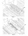
- FIGs 1 - 14 an example of the dishwasher rack (1) and the base (2) of the invention are illustrated; the base (2) is developed to prevent glasses (3) (or kitchen utensils such as wineglasses, mugs, bowls and jars) placed in the rack (1) from slipping and tilting.
- the perspective view of the said base (2) when it is placed in the dishwasher rack (1) is in the horizontal position on the bottom of the rack (1) and this is the open position of the base (2) and a glass (3) can be placed on it (shown in Figures 8 and 9 ).
- a dishwasher rack (1) is formed by several shaped wires. As shown in Figure 2 , there are wires with different functions in the rack (1). For example, there are horizontal and vertical (14, 13) wires encircling the rack (1). On the bottom of the rack (1), there are bottom wires (12) on which miscellaneous kitchen utensils are placed and following these wires (12) there are wires for placing plates (11) shaped in bent form such that the plates can be inserted between them. In the racks, the bottom wires (12) are used horizontally or inclined to some degree. Besides, there are intermediate connection wires (15) on the bottom of the rack (1) which connect the bottom wires (12) to each other (shown in Figures 11 - 12 ).
- FIGs 3, 4 and 10 perspective views of the base (2) placed onto the bottom of the dishwasher rack (1) are given.
- the base (2) shown here has a flat wireframe form and this wireframe form consists of multiple parallel and / or intersecting bars (21).
- the distance between the bars (21) is held equal with the distance between the bottom wires (12) of the rack (1) under the base (2).
- the base (2) On the upper surface of the base (2) (on top of at least one bar (21)), there are multiple teeth (22) formed as recesses and protrusions.
- the glasses (3) are placed on the base (2) such that their head parts are between the teeth (22) (illustrated in Figures 8 - 9 ). By this way, during the movement of the rack (1), the glasses (3) are prevented from slipping.
- the base (2) On the bottom of the base (2), there is at least one hook (23).
- the bottom wires (12) are shrink fitted between these hooks (23) which have the ability to stretch.
- the base (2) is placed on the bottom of the rack (1) such that the bottom wires (12) enter between the hooks (23) of the base (2).
- each of the bottom wires (12) has entered inside the longitudinal groove (26) formed by a hook (23)
- the base (2) is prevented from slipping without control since the bottom wires (12) are shrink fitted to the hooks (23).
- teeth (22) forms are shown in Figures 5 - 7 .
- the teeth (22) in which the head parts of the glasses (3) are inserted may be in triangular, circular, rectangular form or the combination of at least two of these forms.
- the base (2) Another important feature of the base (2) is its ability to open and close around an axis.
- FIG 10 on one side of the base (2), there is an insert with at least one snap fitting (25) which is fitted to the intermediate connection wire (15).
- the base (2) can be mounted to and removed from the intermediate connection wire (15) by these said snap fittings (25).
- the snap fittings (25) are shrink fitted to the intermediate connection wire (15) and the base (2) can make a rotational movement in this position with respect to the axis of the wire (15) and also can be moved back and forth along this wire (15) (or in other words along the axis of the wire (15)).
- the opened and closed positions of the base (2) as a result of this rotation are shown in Figures 11 - 13 .
- Figure 13 when the base (2) is at the vertical position, it is between the glasses (3) and wires for placing plates (11) and therefore in the vertical position it does not cause a substantial loss of the usable volume.
- At least one concave surface (24) has been formed under the base (2).
- This concave surface (24) sits in a balance manner on the two bottom wires (12) when the base (2) is open (in this position, the edges (27) of the surface (24) is at equal distance to both bottom wires (12)).
- the said surface's (24) being concave and this surface's sitting on two bottom wires (12) makes it harder to slip on the bottom wires (12) when compared to bottom of the base (2) being flat.
- the kitchen utensils on the base (2) increase the weight, the functionality of the concave surfaces (24) increases.
- the base (2) prevented from moving back and forth without control.
- the base (2) can take a position by rotating according to the use on the rack (2).
- the user according to the glass (3) placement need, can provide a safe glass (3) placement in the rack (2) by using the base (2) in vertical position as shown in Figure 11 and 13 . Therefore, when the base (2) is vertically positioned, the teeth (22) and wires for placing plates (11) intertwine and the base (2) is prevented from moving back and forth on the intermediate connection wire (15).
- the glasses (3) (or the kitchen utensils) can be made stable by leaning the glasses (3) placed on the bottom wires (12) against the said concave surfaces (24) (glasses' (3) leaning against concave surfaces (24) results in less slipping when compared to leaning against flat surfaces). Therefore, the width of the base (2) and the bent of the wires (11, 12) should be suitable for this.
Abstract
Description
- This invention is related to bases which prevent kitchen utensils such as glass and jars placed in a dishwasher rack from slipping or tilting.
- There exists various studies related to the known state of the art in accordance with the dishwasher racks in which the kitchen utensils to be cleaned are placed. The main problems with the dishwasher racks are to increase the usable area of the racks and make the kitchen utensils placed on these racks steady and organized. In other words, the full capacity and layout of a rack is of great importance. Specially, placing kitchenware of various sizes and various types into racks sometimes raises difficulties to the user. For example, while there are slots specially placed for the plates to be placed into the rack, the glasses are usually placed into the left spaces. In cases where the rack is not completely full these glasses may slip, tilt and in turn may be broken while these racks are being moved back and forth. Therefore, there is a need for various apparatus that can prevent glasses in the rack from slipping and tilting.
- There are several studies about the known state of the art related to this subject and patent application published under patent no
EP1787569 can be given as an example. In this application a glass base made of a flexible material is disclosed. According to this, the base is installed to the bottom of the rack by stretching and several elastic extensions on the base prevent the glasses on it from slipping and tilting. - In the patent application published under patent no
US2005242046 which is another example of the known state of the art, a glass rack that is hung on to the wireframe of the rack is disclosed. This rack is hung higher than the bottom of the rack and the part in which the glasses are inserted can turn. This apparatus which is not appropriate for the glasses to be placed onto the base of the rack, causes reduction in the usable area of the rack due to its parts extending towards inside the rack. - The base of the invention is an apparatus which is placed onto the bottom of the dishwasher racks. The base is made as a wireframe and the parts forming the wireframe are spaced such that they are facing the bottom wires of the rack. Thus, it is achieved that the water spraying from the nozzles can reach inside the kitchen utensils such as glasses, wineglasses, mugs, bowls and jars without obstruction. On upper surface of the base, there are teeth in which head parts of such utensils can enter. By this way these utensil are prevented from slipping on the base. The protrusions located on one side of the base are mounted on the rack wires and said rack wires are held in these protrusions. This connection mechanism allows the base to make a rotational movement with respect to the axis of this wire and by this way allows the base to open and close (between horizontal and vertical positions). The protrusions under the base (in case the base is mounted on the bottom of the rack) are mounted to the wires on the bottom of the rack preventing the base from separating without control. When the base is not in use, it is closed (vertical position) and in this position it does not affect in-rack layout since it occupies a very small space.
- The objective of this invention is to provide a base for placing kitchen utensils such as glasses, wineglasses, mugs, bowls and jars into dishwasher racks.
- Another objective of the invention is to provide a base which can be placed onto the bottom of dishwasher racks, which can be opened and closed and which can prevent the utensils placed on it from slipping.
- Another objective of the invention is to space the parts comprising the wireframe base such that the distance between them is same as the distance between the wires of the rack and by this way making the water spraying from the nozzles reach into the kitchen utensils without obstruction.
- Another objective of the invention is to provide a cheap, reliable and easy-to-mount-and-remove base.
- An example of the base of the invention and the dishwasher rack in which it is used are illustrated in the Figures and the brief descriptions of the Figures are given below:
-
Figure 1 is the perspective view of the base of the invention while the base is placed in the dishwasher rack. -
Figure 2 is the side view of the base while the base is placed in the dishwasher rack. -
Figure 3 is a general perspective view of the base. -
Figure 4 is the detailed perspective view of the base. -
Figure 5-7 are the views of different teeth geometries of the base. -
Figure 8 is the perspective view of the base when a glass is placed on it. -
Figure 9 is the side view of the base when a glass is placed on it. -
Figure 10 is another perspective view of the base. -
Figure 11 is the perspective view of the base in closed position in the dishwasher rack. -
Figure 12 is the detailed perspective view of the base of the invention while the base is placed in the dishwasher rack. -
Figure 13 is the side view of the base in closed position in the dishwasher rack. -
Figure 14 is a view of the position of the base on the rack. - The parts in the figures are individually referenced and these references are:
- Dishwasher rack (1)
- Base (2)
- Glass (3)
- Wires for placing plates (11)
- Base wires (12)
- Vertical wires (13)
- Horizontal wires (14)
- Intermediate connection wires (15)
- Bars (21)
- Teeth (22)
- Hooks (23)
- Concave surfaces (24)
- Snap fitting (25)
- Groove (26)
- Edges of the concave surface (27)
- In
Figures 1 - 14 , an example of the dishwasher rack (1) and the base (2) of the invention are illustrated; the base (2) is developed to prevent glasses (3) (or kitchen utensils such as wineglasses, mugs, bowls and jars) placed in the rack (1) from slipping and tilting. InFigure 1 , the perspective view of the said base (2) when it is placed in the dishwasher rack (1). The base (2) shown here is in the horizontal position on the bottom of the rack (1) and this is the open position of the base (2) and a glass (3) can be placed on it (shown inFigures 8 and9 ). - As known, a dishwasher rack (1) is formed by several shaped wires. As shown in
Figure 2 , there are wires with different functions in the rack (1). For example, there are horizontal and vertical (14, 13) wires encircling the rack (1). On the bottom of the rack (1), there are bottom wires (12) on which miscellaneous kitchen utensils are placed and following these wires (12) there are wires for placing plates (11) shaped in bent form such that the plates can be inserted between them. In the racks, the bottom wires (12) are used horizontally or inclined to some degree. Besides, there are intermediate connection wires (15) on the bottom of the rack (1) which connect the bottom wires (12) to each other (shown inFigures 11 - 12 ). - In
Figures 3, 4 and10 , perspective views of the base (2) placed onto the bottom of the dishwasher rack (1) are given. The base (2) shown here has a flat wireframe form and this wireframe form consists of multiple parallel and / or intersecting bars (21). The distance between the bars (21) is held equal with the distance between the bottom wires (12) of the rack (1) under the base (2). In other words, when the base (2) is placed into the rack (1) there is one bottom wire (12) under each bar (21). Thus, it achieved that the water coming from the washing nozzles of the dishwasher can reach into the said kitchen utensils without any obstruction. - On the upper surface of the base (2) (on top of at least one bar (21)), there are multiple teeth (22) formed as recesses and protrusions. The glasses (3) are placed on the base (2) such that their head parts are between the teeth (22) (illustrated in
Figures 8 - 9 ). By this way, during the movement of the rack (1), the glasses (3) are prevented from slipping. - On the bottom of the base (2), there is at least one hook (23). The bottom wires (12) are shrink fitted between these hooks (23) which have the ability to stretch. The base (2) is placed on the bottom of the rack (1) such that the bottom wires (12) enter between the hooks (23) of the base (2). When each of the bottom wires (12) has entered inside the longitudinal groove (26) formed by a hook (23), it is possible to move the base (2) a little bit back and forth due to the length of the groove (26). Also, the base (2) is prevented from slipping without control since the bottom wires (12) are shrink fitted to the hooks (23).
- Different teeth (22) forms are shown in
Figures 5 - 7 . In accordance with these, the teeth (22) in which the head parts of the glasses (3) are inserted may be in triangular, circular, rectangular form or the combination of at least two of these forms. - As shown in
Figures 8 - 9 , when the glasses (3) are placed on the base (2), a more stable condition can be obtained by leaning the sides of the glasses (3) against the wires for placing plates (11) (for this to be possible, the bottom wires (12) next to the wires for placing plates (11) should be sloped towards wires for placing plates (11)). - Another important feature of the base (2) is its ability to open and close around an axis. As shown in
Figure 10 , on one side of the base (2), there is an insert with at least one snap fitting (25) which is fitted to the intermediate connection wire (15). The base (2) can be mounted to and removed from the intermediate connection wire (15) by these said snap fittings (25). The snap fittings (25) are shrink fitted to the intermediate connection wire (15) and the base (2) can make a rotational movement in this position with respect to the axis of the wire (15) and also can be moved back and forth along this wire (15) (or in other words along the axis of the wire (15)). The opened and closed positions of the base (2) as a result of this rotation are shown inFigures 11 - 13 . As shown inFigure 13 , when the base (2) is at the vertical position, it is between the glasses (3) and wires for placing plates (11) and therefore in the vertical position it does not cause a substantial loss of the usable volume. - Alternatively, at least one concave surface (24) has been formed under the base (2). This concave surface (24) sits in a balance manner on the two bottom wires (12) when the base (2) is open (in this position, the edges (27) of the surface (24) is at equal distance to both bottom wires (12)). In other words, the said surface's (24) being concave and this surface's sitting on two bottom wires (12) makes it harder to slip on the bottom wires (12) when compared to bottom of the base (2) being flat. Also, since the kitchen utensils on the base (2) increase the weight, the functionality of the concave surfaces (24) increases. Thus, the base (2) prevented from moving back and forth without control.
- As seen in
Figures 11 and13 , the base (2) can take a position by rotating according to the use on the rack (2). The user, according to the glass (3) placement need, can provide a safe glass (3) placement in the rack (2) by using the base (2) in vertical position as shown inFigure 11 and13 . Therefore, when the base (2) is vertically positioned, the teeth (22) and wires for placing plates (11) intertwine and the base (2) is prevented from moving back and forth on the intermediate connection wire (15). Again, in this position (Figure 13 ), the glasses (3) (or the kitchen utensils) can be made stable by leaning the glasses (3) placed on the bottom wires (12) against the said concave surfaces (24) (glasses' (3) leaning against concave surfaces (24) results in less slipping when compared to leaning against flat surfaces). Therefore, the width of the base (2) and the bent of the wires (11, 12) should be suitable for this.
Claims (5)
- A base (2) which is mounted on the bottom wires (12) of a dishwasher rack (1); which comprises multiple bars (21) joined as a wireframe; and which comprises multiple teeth (22) shaped as recesses and protrusions between which kitchen utensils such as glasses are placed, wherein the teeth are placed on at least one bar (21); characterized in that
each of the bars (21) are spaced such that they each are on a bottom wire (12);
under the base (2), there is at least one hook (23) engaging the bottom wires (12);
on one side of the base (2), there is at least one snap fitting (25) which is mounted on one of the intermediate connection wires (15) connecting the bottom wires (12); and
in this position, the base (2) can make a rotational movement with respect to the axis of the wire (15) and can be moved back and forth along the wire (15). - A base (2) according to Claim 1 characterized in that, when the hooks (23) are mounted to the bottom wires (12), there is a longitudinal groove (26) in each hook (23) for the base (2) to be moved back and forth a little bit.
- A base (2) according to Claim 1 characterized in that said hooks (23) can be shrink fitted to the bottom wires (12).
- A base (2) according to Claim 1 characterized in that under the base (2), when the base (2) is in vertical position, there is at least one concave surface (24) against which the kitchen utensils lean.
- A base (2) according to Claim 4 characterized in that when the base (2) is placed on the bottom wires (2), the edges (27) of the concave surface (24) is equally distanced to the two bottom wires (12).
Priority Applications (2)
| Application Number | Priority Date | Filing Date | Title |
|---|---|---|---|
| EP09159145A EP2245975B1 (en) | 2009-04-30 | 2009-04-30 | Dish-holder support for dishwasher rack |
| AT09159145T ATE526862T1 (en) | 2009-04-30 | 2009-04-30 | DISH HOLDER SUPPORT FOR DISHWASHER DISHWASHER BASKET |
Applications Claiming Priority (1)
| Application Number | Priority Date | Filing Date | Title |
|---|---|---|---|
| EP09159145A EP2245975B1 (en) | 2009-04-30 | 2009-04-30 | Dish-holder support for dishwasher rack |
Publications (2)
| Publication Number | Publication Date |
|---|---|
| EP2245975A1 true EP2245975A1 (en) | 2010-11-03 |
| EP2245975B1 EP2245975B1 (en) | 2011-10-05 |
Family
ID=41016831
Family Applications (1)
| Application Number | Title | Priority Date | Filing Date |
|---|---|---|---|
| EP09159145A Revoked EP2245975B1 (en) | 2009-04-30 | 2009-04-30 | Dish-holder support for dishwasher rack |
Country Status (2)
| Country | Link |
|---|---|
| EP (1) | EP2245975B1 (en) |
| AT (1) | ATE526862T1 (en) |
Cited By (14)
| Publication number | Priority date | Publication date | Assignee | Title |
|---|---|---|---|---|
| ITTO20110339A1 (en) * | 2011-04-18 | 2012-10-19 | Drahtzug Stein Divisione Omim Divisione Come S | BASKET FOR DISHWASHER MACHINES AND DISHWASHER MACHINE THAT INCORPORATES SUCH BASKET. |
| EP2554095A1 (en) * | 2011-08-05 | 2013-02-06 | Indesit Company S.p.A. | Dishwasher rack comprising tilting and folding supports |
| ITTO20110749A1 (en) * | 2011-08-05 | 2013-02-06 | Indesit Co Spa | DISHWASH SUPPORT POSSIBLE ON THE BOTTOM OF A DISHWASHER BASKET THAT IS ABLE TO CREATE SOFT SURFACES |
| WO2013036468A1 (en) * | 2011-09-05 | 2013-03-14 | Premark Feg L.L.C. | Dish rack for dishwashers |
| ITMI20121044A1 (en) * | 2012-06-15 | 2013-12-16 | Iwt Srl | DEVICE FOR LOADING A WASHING MACHINE WITH COMPONENTS TO BE WASHED AND INCLUDING THIS DEVICE |
| WO2015000508A1 (en) * | 2013-07-02 | 2015-01-08 | Electrolux Appliances Aktiebolag | Dishwasher basket |
| WO2016034202A1 (en) | 2014-09-01 | 2016-03-10 | Electrolux Appliances Aktiebolag | Support assembly |
| CN106539548A (en) * | 2015-09-17 | 2017-03-29 | 博西华电器(江苏)有限公司 | Dish-washing machine |
| JP2017136425A (en) * | 2017-04-06 | 2017-08-10 | リンナイ株式会社 | Dishwasher |
| DE102016208112A1 (en) * | 2016-05-11 | 2017-11-16 | BSH Hausgeräte GmbH | Dish rack for holding items to be washed and dishwasher, in particular household dishwasher |
| US10052012B2 (en) | 2014-09-01 | 2018-08-21 | Electrolux Appliances Aktiebolag | Holding assembly |
| US10165927B2 (en) | 2014-09-01 | 2019-01-01 | Electrolux Appliances Aktiebolag | Holding assembly |
| DE102019220277B3 (en) * | 2019-12-19 | 2021-01-14 | BSH Hausgeräte GmbH | Wash ware holder |
| EP3769657A4 (en) * | 2018-03-20 | 2021-04-28 | Gree Electric Appliances (Wuhan) Co., Ltd. | Cup holder, dishware basket assembly having same, and dishwasher |
Families Citing this family (1)
| Publication number | Priority date | Publication date | Assignee | Title |
|---|---|---|---|---|
| DE102012219818A1 (en) | 2012-10-30 | 2014-04-30 | BSH Bosch und Siemens Hausgeräte GmbH | Dish rack and dishwasher, in particular domestic dishwasher with crockery basket |
Citations (5)
| Publication number | Priority date | Publication date | Assignee | Title |
|---|---|---|---|---|
| US4589556A (en) * | 1985-06-03 | 1986-05-20 | Peretz Steven I | Holder assembly for stemmed glassware and like objects |
| US20050242046A1 (en) | 2004-05-03 | 2005-11-03 | Lee Kang H | Auxiliary rack and automatic dishwasher using the same |
| EP1787569A1 (en) | 2005-11-16 | 2007-05-23 | Electrolux Home Products Corporation N.V. | Storing device for a dishwashing machine |
| DE102006007330A1 (en) * | 2006-02-16 | 2007-08-30 | BSH Bosch und Siemens Hausgeräte GmbH | Household-dishwasher has bars, whose one end is arranged at crockery basket, where another end of bars serves for holding of hollow container and swivel-mounting of holding device is formed at crockery basket |
| JP2007282755A (en) * | 2006-04-14 | 2007-11-01 | Matsushita Electric Ind Co Ltd | Dishwasher |
-
2009
- 2009-04-30 AT AT09159145T patent/ATE526862T1/en not_active IP Right Cessation
- 2009-04-30 EP EP09159145A patent/EP2245975B1/en not_active Revoked
Patent Citations (5)
| Publication number | Priority date | Publication date | Assignee | Title |
|---|---|---|---|---|
| US4589556A (en) * | 1985-06-03 | 1986-05-20 | Peretz Steven I | Holder assembly for stemmed glassware and like objects |
| US20050242046A1 (en) | 2004-05-03 | 2005-11-03 | Lee Kang H | Auxiliary rack and automatic dishwasher using the same |
| EP1787569A1 (en) | 2005-11-16 | 2007-05-23 | Electrolux Home Products Corporation N.V. | Storing device for a dishwashing machine |
| DE102006007330A1 (en) * | 2006-02-16 | 2007-08-30 | BSH Bosch und Siemens Hausgeräte GmbH | Household-dishwasher has bars, whose one end is arranged at crockery basket, where another end of bars serves for holding of hollow container and swivel-mounting of holding device is formed at crockery basket |
| JP2007282755A (en) * | 2006-04-14 | 2007-11-01 | Matsushita Electric Ind Co Ltd | Dishwasher |
Cited By (23)
| Publication number | Priority date | Publication date | Assignee | Title |
|---|---|---|---|---|
| ITTO20110339A1 (en) * | 2011-04-18 | 2012-10-19 | Drahtzug Stein Divisione Omim Divisione Come S | BASKET FOR DISHWASHER MACHINES AND DISHWASHER MACHINE THAT INCORPORATES SUCH BASKET. |
| EP2946716A1 (en) * | 2011-08-05 | 2015-11-25 | Indesit Company S.p.A. | Dishwasher rack comprising tilting supports having slots |
| EP2554095A1 (en) * | 2011-08-05 | 2013-02-06 | Indesit Company S.p.A. | Dishwasher rack comprising tilting and folding supports |
| ITTO20110749A1 (en) * | 2011-08-05 | 2013-02-06 | Indesit Co Spa | DISHWASH SUPPORT POSSIBLE ON THE BOTTOM OF A DISHWASHER BASKET THAT IS ABLE TO CREATE SOFT SURFACES |
| ITTO20110742A1 (en) * | 2011-08-05 | 2013-02-06 | Indesit Co Spa | BASKET FOR DISHWASHER MACHINE INCLUDING FOLDING AND FOLDABLE SUPPORTS THAT DO NOT TENSE THE BASKET WIRES |
| EP2554101A1 (en) * | 2011-08-05 | 2013-02-06 | Indesit Company, S.p.A. | Crockery support which can be positioned on the bottom of a dishwasher rack to create soft surfaces |
| EP2949257A1 (en) * | 2011-08-05 | 2015-12-02 | Indesit Company S.p.A. | Dishwasher rack comprising tilting supports having snap-on hooks |
| WO2013036468A1 (en) * | 2011-09-05 | 2013-03-14 | Premark Feg L.L.C. | Dish rack for dishwashers |
| EP2674093A1 (en) * | 2012-06-15 | 2013-12-18 | IWT S.r.L. | Device for loading a washing machine with components to be washed and apparatus comprising this device |
| ITMI20121044A1 (en) * | 2012-06-15 | 2013-12-16 | Iwt Srl | DEVICE FOR LOADING A WASHING MACHINE WITH COMPONENTS TO BE WASHED AND INCLUDING THIS DEVICE |
| WO2015000508A1 (en) * | 2013-07-02 | 2015-01-08 | Electrolux Appliances Aktiebolag | Dishwasher basket |
| US10165927B2 (en) | 2014-09-01 | 2019-01-01 | Electrolux Appliances Aktiebolag | Holding assembly |
| US10052012B2 (en) | 2014-09-01 | 2018-08-21 | Electrolux Appliances Aktiebolag | Holding assembly |
| WO2016034202A1 (en) | 2014-09-01 | 2016-03-10 | Electrolux Appliances Aktiebolag | Support assembly |
| US10463226B2 (en) | 2014-09-01 | 2019-11-05 | Electrolux Appliances Aktiebolag | Support assembly |
| CN106539548A (en) * | 2015-09-17 | 2017-03-29 | 博西华电器(江苏)有限公司 | Dish-washing machine |
| DE102016208112A1 (en) * | 2016-05-11 | 2017-11-16 | BSH Hausgeräte GmbH | Dish rack for holding items to be washed and dishwasher, in particular household dishwasher |
| DE102016208112B4 (en) * | 2016-05-11 | 2018-10-11 | BSH Hausgeräte GmbH | Dish rack for holding items to be washed and dishwasher, in particular household dishwasher |
| JP2017136425A (en) * | 2017-04-06 | 2017-08-10 | リンナイ株式会社 | Dishwasher |
| EP3769657A4 (en) * | 2018-03-20 | 2021-04-28 | Gree Electric Appliances (Wuhan) Co., Ltd. | Cup holder, dishware basket assembly having same, and dishwasher |
| DE102019220277B3 (en) * | 2019-12-19 | 2021-01-14 | BSH Hausgeräte GmbH | Wash ware holder |
| WO2021122025A1 (en) | 2019-12-19 | 2021-06-24 | BSH Hausgeräte GmbH | Dish rack |
| US11826004B2 (en) | 2019-12-19 | 2023-11-28 | BSH Hausgeräte GmbH | Dish rack |
Also Published As
| Publication number | Publication date |
|---|---|
| ATE526862T1 (en) | 2011-10-15 |
| EP2245975B1 (en) | 2011-10-05 |
Similar Documents
| Publication | Publication Date | Title |
|---|---|---|
| EP2245975B1 (en) | Dish-holder support for dishwasher rack | |
| EP1707101B1 (en) | Utensil rack and automatic dishwasher comprising said utensil rack | |
| US6571965B1 (en) | Dishwasher rack with pivotable fences | |
| US5351837A (en) | Dishwasher rack assembly with fold down combs | |
| US7909181B2 (en) | Article holders | |
| EP2292140B1 (en) | Silverware container, especially silverware tray and/or silverware basket, as well as dishwasher with such a silverware container | |
| US8757419B2 (en) | Crockery basket comprising height-adjustable racks | |
| US8167147B2 (en) | Dish drainer | |
| US9119524B2 (en) | Dishwasher rack insert | |
| EP2554097A2 (en) | Dishwasher rack comprising an extractable perimetric frame | |
| EP2798996B1 (en) | Removable glass-holding insert for dishwasher rack | |
| EP1854395A1 (en) | Dishwasher with utensil rack and slides therefor | |
| EP3164045B1 (en) | Dishwasher comprising a wire rack with an improved carrier adaptor structure | |
| EP0729725A1 (en) | Multi-functional dish holder | |
| US7665475B2 (en) | Utility shelf for a dishwasher dish rack | |
| US20110303626A1 (en) | Sink rack and system for supporting large frying pans horizontally within the confines of a kitchen sink | |
| EP2934277B1 (en) | Cutlery rack | |
| KR20070039542A (en) | Crockery basket for receiving crockery in a variable manner | |
| US20040079713A1 (en) | Dishwasher utility basket | |
| EP3188643B1 (en) | A dishwasher wire rack having an improved carrier adaptor tine assembly structure | |
| EP2074925A1 (en) | Rack mechanism attachable to a dish washing machine basket | |
| EP2036482A1 (en) | Support for glasses for dishwasher baskets | |
| KR20210001373A (en) | Grooming shelf of Kitchen utensils | |
| EP2554094A1 (en) | A dishwasher rack with shelf for supporting objects | |
| DE102011085417B4 (en) | Dish rack for a dishwasher, in particular domestic dishwasher |
Legal Events
| Date | Code | Title | Description |
|---|---|---|---|
| PUAI | Public reference made under article 153(3) epc to a published international application that has entered the european phase |
Free format text: ORIGINAL CODE: 0009012 |
|
| AK | Designated contracting states |
Kind code of ref document: A1 Designated state(s): AT BE BG CH CY CZ DE DK EE ES FI FR GB GR HR HU IE IS IT LI LT LU LV MC MK MT NL NO PL PT RO SE SI SK TR |
|
| 17P | Request for examination filed |
Effective date: 20110114 |
|
| 17Q | First examination report despatched |
Effective date: 20110204 |
|
| GRAP | Despatch of communication of intention to grant a patent |
Free format text: ORIGINAL CODE: EPIDOSNIGR1 |
|
| GRAS | Grant fee paid |
Free format text: ORIGINAL CODE: EPIDOSNIGR3 |
|
| GRAA | (expected) grant |
Free format text: ORIGINAL CODE: 0009210 |
|
| AK | Designated contracting states |
Kind code of ref document: B1 Designated state(s): AT BE BG CH CY CZ DE DK EE ES FI FR GB GR HR HU IE IS IT LI LT LU LV MC MK MT NL NO PL PT RO SE SI SK TR |
|
| REG | Reference to a national code |
Ref country code: GB Ref legal event code: FG4D |
|
| REG | Reference to a national code |
Ref country code: CH Ref legal event code: EP |
|
| REG | Reference to a national code |
Ref country code: IE Ref legal event code: FG4D |
|
| REG | Reference to a national code |
Ref country code: DE Ref legal event code: R096 Ref document number: 602009002909 Country of ref document: DE Effective date: 20111201 |
|
| REG | Reference to a national code |
Ref country code: NL Ref legal event code: VDEP Effective date: 20111005 |
|
| REG | Reference to a national code |
Ref country code: ES Ref legal event code: FG2A Ref document number: 2375044 Country of ref document: ES Kind code of ref document: T3 Effective date: 20120224 |
|
| PG25 | Lapsed in a contracting state [announced via postgrant information from national office to epo] |
Ref country code: SI Free format text: LAPSE BECAUSE OF FAILURE TO SUBMIT A TRANSLATION OF THE DESCRIPTION OR TO PAY THE FEE WITHIN THE PRESCRIBED TIME-LIMIT Effective date: 20111005 |
|
| LTIE | Lt: invalidation of european patent or patent extension |
Effective date: 20111005 |
|
| REG | Reference to a national code |
Ref country code: AT Ref legal event code: MK05 Ref document number: 526862 Country of ref document: AT Kind code of ref document: T Effective date: 20111005 |
|
| PG25 | Lapsed in a contracting state [announced via postgrant information from national office to epo] |
Ref country code: LT Free format text: LAPSE BECAUSE OF FAILURE TO SUBMIT A TRANSLATION OF THE DESCRIPTION OR TO PAY THE FEE WITHIN THE PRESCRIBED TIME-LIMIT Effective date: 20111005 Ref country code: BE Free format text: LAPSE BECAUSE OF FAILURE TO SUBMIT A TRANSLATION OF THE DESCRIPTION OR TO PAY THE FEE WITHIN THE PRESCRIBED TIME-LIMIT Effective date: 20111005 Ref country code: IS Free format text: LAPSE BECAUSE OF FAILURE TO SUBMIT A TRANSLATION OF THE DESCRIPTION OR TO PAY THE FEE WITHIN THE PRESCRIBED TIME-LIMIT Effective date: 20120205 Ref country code: NO Free format text: LAPSE BECAUSE OF FAILURE TO SUBMIT A TRANSLATION OF THE DESCRIPTION OR TO PAY THE FEE WITHIN THE PRESCRIBED TIME-LIMIT Effective date: 20120105 |
|
| PG25 | Lapsed in a contracting state [announced via postgrant information from national office to epo] |
Ref country code: GR Free format text: LAPSE BECAUSE OF FAILURE TO SUBMIT A TRANSLATION OF THE DESCRIPTION OR TO PAY THE FEE WITHIN THE PRESCRIBED TIME-LIMIT Effective date: 20120106 Ref country code: PT Free format text: LAPSE BECAUSE OF FAILURE TO SUBMIT A TRANSLATION OF THE DESCRIPTION OR TO PAY THE FEE WITHIN THE PRESCRIBED TIME-LIMIT Effective date: 20120206 Ref country code: SE Free format text: LAPSE BECAUSE OF FAILURE TO SUBMIT A TRANSLATION OF THE DESCRIPTION OR TO PAY THE FEE WITHIN THE PRESCRIBED TIME-LIMIT Effective date: 20111005 Ref country code: LV Free format text: LAPSE BECAUSE OF FAILURE TO SUBMIT A TRANSLATION OF THE DESCRIPTION OR TO PAY THE FEE WITHIN THE PRESCRIBED TIME-LIMIT Effective date: 20111005 Ref country code: NL Free format text: LAPSE BECAUSE OF FAILURE TO SUBMIT A TRANSLATION OF THE DESCRIPTION OR TO PAY THE FEE WITHIN THE PRESCRIBED TIME-LIMIT Effective date: 20111005 Ref country code: HR Free format text: LAPSE BECAUSE OF FAILURE TO SUBMIT A TRANSLATION OF THE DESCRIPTION OR TO PAY THE FEE WITHIN THE PRESCRIBED TIME-LIMIT Effective date: 20111005 |
|
| PG25 | Lapsed in a contracting state [announced via postgrant information from national office to epo] |
Ref country code: CY Free format text: LAPSE BECAUSE OF FAILURE TO SUBMIT A TRANSLATION OF THE DESCRIPTION OR TO PAY THE FEE WITHIN THE PRESCRIBED TIME-LIMIT Effective date: 20111005 |
|
| PLBI | Opposition filed |
Free format text: ORIGINAL CODE: 0009260 |
|
| PG25 | Lapsed in a contracting state [announced via postgrant information from national office to epo] |
Ref country code: CZ Free format text: LAPSE BECAUSE OF FAILURE TO SUBMIT A TRANSLATION OF THE DESCRIPTION OR TO PAY THE FEE WITHIN THE PRESCRIBED TIME-LIMIT Effective date: 20111005 Ref country code: SK Free format text: LAPSE BECAUSE OF FAILURE TO SUBMIT A TRANSLATION OF THE DESCRIPTION OR TO PAY THE FEE WITHIN THE PRESCRIBED TIME-LIMIT Effective date: 20111005 Ref country code: DK Free format text: LAPSE BECAUSE OF FAILURE TO SUBMIT A TRANSLATION OF THE DESCRIPTION OR TO PAY THE FEE WITHIN THE PRESCRIBED TIME-LIMIT Effective date: 20111005 Ref country code: EE Free format text: LAPSE BECAUSE OF FAILURE TO SUBMIT A TRANSLATION OF THE DESCRIPTION OR TO PAY THE FEE WITHIN THE PRESCRIBED TIME-LIMIT Effective date: 20111005 Ref country code: BG Free format text: LAPSE BECAUSE OF FAILURE TO SUBMIT A TRANSLATION OF THE DESCRIPTION OR TO PAY THE FEE WITHIN THE PRESCRIBED TIME-LIMIT Effective date: 20120105 |
|
| PGFP | Annual fee paid to national office [announced via postgrant information from national office to epo] |
Ref country code: IE Payment date: 20120427 Year of fee payment: 4 |
|
| PLAX | Notice of opposition and request to file observation + time limit sent |
Free format text: ORIGINAL CODE: EPIDOSNOBS2 |
|
| 26 | Opposition filed |
Opponent name: ARCELIK ANONIM SIRKETI Effective date: 20120705 |
|
| PG25 | Lapsed in a contracting state [announced via postgrant information from national office to epo] |
Ref country code: PL Free format text: LAPSE BECAUSE OF FAILURE TO SUBMIT A TRANSLATION OF THE DESCRIPTION OR TO PAY THE FEE WITHIN THE PRESCRIBED TIME-LIMIT Effective date: 20111005 Ref country code: RO Free format text: LAPSE BECAUSE OF FAILURE TO SUBMIT A TRANSLATION OF THE DESCRIPTION OR TO PAY THE FEE WITHIN THE PRESCRIBED TIME-LIMIT Effective date: 20111005 |
|
| PGFP | Annual fee paid to national office [announced via postgrant information from national office to epo] |
Ref country code: IT Payment date: 20120430 Year of fee payment: 4 |
|
| REG | Reference to a national code |
Ref country code: DE Ref legal event code: R026 Ref document number: 602009002909 Country of ref document: DE Effective date: 20120705 |
|
| PG25 | Lapsed in a contracting state [announced via postgrant information from national office to epo] |
Ref country code: MC Free format text: LAPSE BECAUSE OF NON-PAYMENT OF DUE FEES Effective date: 20120430 |
|
| PGFP | Annual fee paid to national office [announced via postgrant information from national office to epo] |
Ref country code: ES Payment date: 20120416 Year of fee payment: 4 |
|
| PG25 | Lapsed in a contracting state [announced via postgrant information from national office to epo] |
Ref country code: AT Free format text: LAPSE BECAUSE OF FAILURE TO SUBMIT A TRANSLATION OF THE DESCRIPTION OR TO PAY THE FEE WITHIN THE PRESCRIBED TIME-LIMIT Effective date: 20111005 |
|
| PG25 | Lapsed in a contracting state [announced via postgrant information from national office to epo] |
Ref country code: MK Free format text: LAPSE BECAUSE OF FAILURE TO SUBMIT A TRANSLATION OF THE DESCRIPTION OR TO PAY THE FEE WITHIN THE PRESCRIBED TIME-LIMIT Effective date: 20111005 |
|
| PG25 | Lapsed in a contracting state [announced via postgrant information from national office to epo] |
Ref country code: FI Free format text: LAPSE BECAUSE OF FAILURE TO SUBMIT A TRANSLATION OF THE DESCRIPTION OR TO PAY THE FEE WITHIN THE PRESCRIBED TIME-LIMIT Effective date: 20111005 |
|
| PG25 | Lapsed in a contracting state [announced via postgrant information from national office to epo] |
Ref country code: MT Free format text: LAPSE BECAUSE OF FAILURE TO SUBMIT A TRANSLATION OF THE DESCRIPTION OR TO PAY THE FEE WITHIN THE PRESCRIBED TIME-LIMIT Effective date: 20111005 |
|
| REG | Reference to a national code |
Ref country code: CH Ref legal event code: PL |
|
| REG | Reference to a national code |
Ref country code: IE Ref legal event code: MM4A |
|
| PG25 | Lapsed in a contracting state [announced via postgrant information from national office to epo] |
Ref country code: LI Free format text: LAPSE BECAUSE OF NON-PAYMENT OF DUE FEES Effective date: 20130430 Ref country code: CH Free format text: LAPSE BECAUSE OF NON-PAYMENT OF DUE FEES Effective date: 20130430 |
|
| PG25 | Lapsed in a contracting state [announced via postgrant information from national office to epo] |
Ref country code: IT Free format text: LAPSE BECAUSE OF NON-PAYMENT OF DUE FEES Effective date: 20130430 |
|
| PG25 | Lapsed in a contracting state [announced via postgrant information from national office to epo] |
Ref country code: IE Free format text: LAPSE BECAUSE OF NON-PAYMENT OF DUE FEES Effective date: 20130430 |
|
| PG25 | Lapsed in a contracting state [announced via postgrant information from national office to epo] |
Ref country code: LU Free format text: LAPSE BECAUSE OF NON-PAYMENT OF DUE FEES Effective date: 20120430 |
|
| REG | Reference to a national code |
Ref country code: ES Ref legal event code: FD2A Effective date: 20140609 |
|
| PG25 | Lapsed in a contracting state [announced via postgrant information from national office to epo] |
Ref country code: HU Free format text: LAPSE BECAUSE OF FAILURE TO SUBMIT A TRANSLATION OF THE DESCRIPTION OR TO PAY THE FEE WITHIN THE PRESCRIBED TIME-LIMIT Effective date: 20090430 |
|
| PG25 | Lapsed in a contracting state [announced via postgrant information from national office to epo] |
Ref country code: ES Free format text: LAPSE BECAUSE OF NON-PAYMENT OF DUE FEES Effective date: 20130501 |
|
| REG | Reference to a national code |
Ref country code: FR Ref legal event code: PLFP Year of fee payment: 7 |
|
| PGFP | Annual fee paid to national office [announced via postgrant information from national office to epo] |
Ref country code: GB Payment date: 20150310 Year of fee payment: 7 Ref country code: TR Payment date: 20150318 Year of fee payment: 7 |
|
| PGFP | Annual fee paid to national office [announced via postgrant information from national office to epo] |
Ref country code: DE Payment date: 20150619 Year of fee payment: 7 |
|
| PGFP | Annual fee paid to national office [announced via postgrant information from national office to epo] |
Ref country code: FR Payment date: 20150330 Year of fee payment: 7 |
|
| PLAY | Examination report in opposition despatched + time limit |
Free format text: ORIGINAL CODE: EPIDOSNORE2 |
|
| PLBC | Reply to examination report in opposition received |
Free format text: ORIGINAL CODE: EPIDOSNORE3 |
|
| RDAF | Communication despatched that patent is revoked |
Free format text: ORIGINAL CODE: EPIDOSNREV1 |
|
| REG | Reference to a national code |
Ref country code: DE Ref legal event code: R064 Ref document number: 602009002909 Country of ref document: DE Ref country code: DE Ref legal event code: R103 Ref document number: 602009002909 Country of ref document: DE |
|
| REG | Reference to a national code |
Ref country code: DE Ref legal event code: R119 Ref document number: 602009002909 Country of ref document: DE |
|
| RDAE | Information deleted related to despatch of communication that patent is revoked |
Free format text: ORIGINAL CODE: EPIDOSDREV1 |
|
| RDAF | Communication despatched that patent is revoked |
Free format text: ORIGINAL CODE: EPIDOSNREV1 |
|
| STAA | Information on the status of an ep patent application or granted ep patent |
Free format text: STATUS: THE PATENT HAS BEEN GRANTED |
|
| GBPC | Gb: european patent ceased through non-payment of renewal fee |
Effective date: 20160430 |
|
| RDAG | Patent revoked |
Free format text: ORIGINAL CODE: 0009271 |
|
| REG | Reference to a national code |
Ref country code: FR Ref legal event code: ST Effective date: 20161230 |
|
| STAA | Information on the status of an ep patent application or granted ep patent |
Free format text: STATUS: PATENT REVOKED |
|
| PG25 | Lapsed in a contracting state [announced via postgrant information from national office to epo] |
Ref country code: DE Free format text: LAPSE BECAUSE OF NON-PAYMENT OF DUE FEES Effective date: 20161101 Ref country code: FR Free format text: LAPSE BECAUSE OF NON-PAYMENT OF DUE FEES Effective date: 20160502 Ref country code: GB Free format text: LAPSE BECAUSE OF NON-PAYMENT OF DUE FEES Effective date: 20160430 |
|
| 27W | Patent revoked |
Effective date: 20161024 |
|
| STAA | Information on the status of an ep patent application or granted ep patent |
Free format text: STATUS: PATENT REVOKED |