EP2245732B1 - Digital excitation control system for an electrical generator and an associated method of use - Google Patents
Digital excitation control system for an electrical generator and an associated method of use Download PDFInfo
- Publication number
- EP2245732B1 EP2245732B1 EP09706546.0A EP09706546A EP2245732B1 EP 2245732 B1 EP2245732 B1 EP 2245732B1 EP 09706546 A EP09706546 A EP 09706546A EP 2245732 B1 EP2245732 B1 EP 2245732B1
- Authority
- EP
- European Patent Office
- Prior art keywords
- output voltage
- generator
- exciter
- voltage
- pid controller
- Prior art date
- Legal status (The legal status is an assumption and is not a legal conclusion. Google has not performed a legal analysis and makes no representation as to the accuracy of the status listed.)
- Active
Links
Images








Classifications
-
- H—ELECTRICITY
- H02—GENERATION; CONVERSION OR DISTRIBUTION OF ELECTRIC POWER
- H02P—CONTROL OR REGULATION OF ELECTRIC MOTORS, ELECTRIC GENERATORS OR DYNAMO-ELECTRIC CONVERTERS; CONTROLLING TRANSFORMERS, REACTORS OR CHOKE COILS
- H02P9/00—Arrangements for controlling electric generators for the purpose of obtaining a desired output
- H02P9/10—Control effected upon generator excitation circuit to reduce harmful effects of overloads or transients, e.g. sudden application of load, sudden removal of load, sudden change of load
- H02P9/102—Control effected upon generator excitation circuit to reduce harmful effects of overloads or transients, e.g. sudden application of load, sudden removal of load, sudden change of load for limiting effects of transients
-
- G—PHYSICS
- G05—CONTROLLING; REGULATING
- G05B—CONTROL OR REGULATING SYSTEMS IN GENERAL; FUNCTIONAL ELEMENTS OF SUCH SYSTEMS; MONITORING OR TESTING ARRANGEMENTS FOR SUCH SYSTEMS OR ELEMENTS
- G05B11/00—Automatic controllers
- G05B11/01—Automatic controllers electric
- G05B11/36—Automatic controllers electric with provision for obtaining particular characteristics, e.g. proportional, integral, differential
- G05B11/42—Automatic controllers electric with provision for obtaining particular characteristics, e.g. proportional, integral, differential for obtaining a characteristic which is both proportional and time-dependent, e.g. P. I., P. I. D.
-
- G—PHYSICS
- G05—CONTROLLING; REGULATING
- G05B—CONTROL OR REGULATING SYSTEMS IN GENERAL; FUNCTIONAL ELEMENTS OF SUCH SYSTEMS; MONITORING OR TESTING ARRANGEMENTS FOR SUCH SYSTEMS OR ELEMENTS
- G05B13/00—Adaptive control systems, i.e. systems automatically adjusting themselves to have a performance which is optimum according to some preassigned criterion
- G05B13/02—Adaptive control systems, i.e. systems automatically adjusting themselves to have a performance which is optimum according to some preassigned criterion electric
- G05B13/04—Adaptive control systems, i.e. systems automatically adjusting themselves to have a performance which is optimum according to some preassigned criterion electric involving the use of models or simulators
- G05B13/042—Adaptive control systems, i.e. systems automatically adjusting themselves to have a performance which is optimum according to some preassigned criterion electric involving the use of models or simulators in which a parameter or coefficient is automatically adjusted to optimise the performance
- G05B13/044—Adaptive control systems, i.e. systems automatically adjusting themselves to have a performance which is optimum according to some preassigned criterion electric involving the use of models or simulators in which a parameter or coefficient is automatically adjusted to optimise the performance not using a perturbation signal
Definitions
- An electrical generator typically operates by rotating a coil of wire relative to a magnetic field (or vice versa). In modern electrical generators, this magnetic field is typically generated using electromagnets known as field coils. An electrical current in these field coils provides the magnetic field necessary to induce an electrical current in the main generator coil. The current and voltage output of the main generator depends on the current in the field coils. Thus, as the generator load changes, the magnetic field strength must be adjusted in an attempt to maintain constant generator output. This is achieved by regulating the current in the field coils. Thus, it is desirable to regulate continuously the current in the field coils.
- the electrical current in the field coils is provided by an exciter generator.
- the problem of regulating the main generator field strength is typically achieved by regulating the output of the exciter generator.
- the exciter generator can include its own exciter field coils, in which case the output of the exciter generator can be controlled by regulating the current supplied to the exciter field coils.
- the output of a voltage regulator can provide power to the field coils of an exciter or generator.
- the voltage regulator can therefore be used to control the output of an exciter generator, and thereby control the output of a main generator.
- One important purpose of a voltage regulator is to maintain the output of a main generator at a constant voltage, known as the "set point,” under various conditions. The difference between the set point and the actual main generator output is "error.”
- PID Proportional, Integral, and Derivative
- a PID controller monitors the output of the generator and adjusts its own output depending on sensed generator output. As the name implies, the PID controller provides three types of control: proportional, integral, and derivative. Proportional control responds in proportion to the error. Integral control responds to the sum of previous errors. Derivative control responds to the rate of change of the error.
- the basic block diagram of a PID block utilized in the automatic voltage regulator control loop is generally indicated by numeral 10.
- the system loop gain K G provides an adjustable term to compensate for variations in system input voltage to a power converting bridge.
- the generator reference voltage V REF 12 is summed 16 with the sensed voltage V C 14 to form a voltage error signal. It is multiplied by the loop gain K G 18. This scaled voltage error signal is utilized to generate three terms with corresponding gains, the proportional gain K P 20, the integral gain K I 22 and the derivative gain K D 24.
- the integral term is limited by an upper summation value of max field forcing V RLMT 26 divided by power input voltage V P 28.
- the integral term and the derivative term are summed together 30 and then this summation is summed 32 with the proportional term. This summed value 32 is multiplied by the power input voltage V P 34 to provide the voltage regulator output V R 36.
- the relative weights of these three types of control in a PID controller must be set for accurate control of the generator output. Choosing these relative weights is known as "tuning" the PID controller. The goal is to achieve a "fast" excitation system that will respond to a disturbance by quickly bringing the generator output back to the set point. An ideal excitation system achieves the set point with as little overshoot and undershoot as possible. Overshoot occurs when the controller provides too much current, thereby causing a "spike” in main generator output. Undershoot occurs when the controller provides too little current, thereby causing a "dip” in main generator output. A poorly tuned PID controller will result in poor performance, e.g., overshoot, undershoot, or slow response time.
- a well-tuned excitation system offers benefits in overall operating performance by responding quickly to transient conditions such as system faults, disturbances, and motor starting. After a fault, a fast excitation system will improve transient stability by holding up the system voltage and providing positive damping to system oscillations. A well-tuned excitation system will minimize voltage overshoot after a disturbance and avoid the nuisance tripping of generator protection circuits.
- a motor When a motor is powered by a generator, the motor presents a large load while the motor is starting, which can cause the generator output voltage to dip. A dip in generator output voltage can cause damage to the motor as the motor will increase its current consumption and heats up due to resistive heating within the motor.
- a fast excitation system will minimize the generator voltage dip and reduce the heating losses of the motor.
- the controller gains are determined using several excitation system parameters, such as voltage loop gain, open circuit time constants, and so forth. These parameters vary not only with the system loading conditions, as generally illustrated by numeral 38 in Fig. 2 , but also system configuration dependent gains such as power input voltage.
- time constant The main time constants of concern are the exciter time constant and the generator time constant. In the present invention, these time constants are estimated and taken into account when tuning the PID controller, thereby achieving improved performance.
- the present invention is directed to overcoming one or more of the problems set forth above.
- the calculated PID gains are fixed during commissioning. No further tuning is conducted during normal operation. The benefit of this approach is that no supervision is needed to prevent undesirable responses caused by a transient behavior of the PID gain estimation.
- a system for self-tuning a PID controller utilized with an exciter and generator includes a power source, an exciter electrically connected to the power source, a generator that is electrically energized by the exciter, and a processor that provides a PID controller that calculates system gain, an estimated exciter time constant and an estimated generator time constant using a recursive least square with forgetting factor algorithm, wherein the estimated exciter time constant and the estimated generator time constant are utilized to calculate PID gains by the processor.
- a system for self-tuning a PID controller utilized with an exciter and generator includes a power source, an exciter electrically connected to the power source, a generator that is electrically energized by the exciter, and a processor that provides a PID controller that calculates system gain, an estimated exciter time constant and an estimated generator time constant with a recursive least square with forgetting factor algorithm, wherein the estimated exciter time constant and the estimated generator time constant are utilized to calculate PID gains by the processor, wherein the processor includes a random input generator that is summed with the output of the PID controller as input to determine the PID gains using the estimated exciter time constant and the estimated generator time constant and the processor compares a digital value of rms generator voltage against a reference voltage as input into the PID controller.
- a system for self-tuning a PID controller utilized with an exciter and generator includes a power source, an exciter electrically connected to the power source, a generator that is electrically energized by the exciter, a first processor that provides a PID controller that calculates system gain, an estimated exciter time constant and an estimated generator time constant with a recursive least square with forgetting factor algorithm, wherein the estimated exciter time constant and the estimated generator time constant are utilized to calculate PID gains by the first processor, wherein the processor includes a random input generator that is summed with the output of the PID controller as input to determine the PID gains using the estimated exciter time constant and the estimated generator time constant and the first processor compares a digital value of rms generator voltage against a reference voltage as input into the PID controller, a second processor controls a self-tuning mode and obtains operating status while obtaining the estimated exciter time constant, the estimated generator time constant and the PID gains from the first
- a method for self-tuning a PID controller utilized with an exciter and generator includes calculating system gain with a processor that also operates as a PID controller, calculating an estimated exciter time constant and an estimated generator time constant with a recursive least square with forgetting factor algorithm with the processor, utilizing the estimated exciter time constant and the estimated generator time constant to calculate PID gains with the processor, self-tuning the PID gains, with the processor, to control exciter field voltage to an exciter, wherein the exciter electrically connected to the power source and a generator is electrically energized by the exciter.
- An embodiment of the present invention relates to an automatic algorithm for tuning a PID controller using a Particle Swarm Optimization (PSO) technique.
- PSO Particle Swarm Optimization
- the PSO technique is used to estimate time constants for an exciter and generator in an excitation system.
- the estimated exciter and generator time constants are used to calculate PID gains (proportional gain K P , integral gain K I and derivative gain K D ).
- the calculated PID gains are fixed during commissioning. Preferably, no further tuning is conducted during normal operation.
- no supervision is needed to prevent undesirable responses caused by a transient behavior of the PID gain estimation.
- a system for self-tuning a PID controller utilized with an exciter and generator includes a power source, an exciter electrically connected to the power source, a generator that is electrically energized by the exciter, and a processor that provides a PID controller that calculates an estimated exciter time constant and an estimated generator time constant using particle swarm optimization to control exciter field voltage.
- a system for self-tuning a PID controller utilized with an exciter and generator includes a power source, an exciter electrically connected to the power source, a generator that is electrically energized by the exciter, and a processor that provides a PID controller that performs a system step response by increasing the voltage reference by a predetermined percentage over a predetermined time period, initializes each particle position of exciter time constant and generator time constant, calculates generator voltage, performs a fitness evaluation and then obtains and updates best values and then repeats calculating the generator voltage, the fitness evaluation and the best values over a predetermined number of iterations.
- a system for self-tuning a PID controller utilized with an exciter and generator includes a power source, an exciter electrically connected to the power source, a generator that is electrically energized by the exciter, a first processor that provides a PID controller with a combination of a reference voltage, a system step response by increasing the voltage reference by a predetermined percentage over a predetermined time period and a calculated generator voltage, and a second processor that receives the system step response and the calculated generator voltage through a communications link and then compares a simulation of a step response using the system step response and measured step response from a voltage regulator and then performs an adjustment using particle swarm optimization which is then provided to the simulation of a step response and also utilized in calculating an estimated exciter time constant, an estimated generator time constant, and PID gains, which are then provided through the communications link to the first processor, wherein the second processor controls a self-tuning mode and obtains operating status, which includes at least one of the estimated
- a method for self-tuning a PID controller utilized with an exciter and generator includes calculating an estimated exciter time constant and an estimated generator time constant with particle swarm optimization with a processor that provides a PID controller, and utilizing the estimated exciter time constant and the estimated generator time constant to calculate PID gains with the processor to control exciter field voltage to an exciter, wherein the exciter electrically connected to the power source and a generator is electrically energized by the exciter.
- a Particle Swarm Optimization Approach for Optimum Design of PID Controller in AVR System IEEE Trans. Energy Convers., Vol. 19 No. 2, June 2004, by Zwe-Lee Gaing discloses a Particle Swarm Optimization Approach for optimizing three controller parameters of a PID controller in a voltage regulator, based on linearized models of a PID controller, an amplifier, an exciter, a generator, and a sensor, based on various time-domain performance criteria.
- Nonlinear Identification and Control of a Turbogenerator - An On-Line Scheduled Multiple Model/Controller Approach IEEE Trans. Energy Convers., Vol. 20 No.
- a self-tuning recursive least squares algorithm is represented as follows:
- G(s) K S 1 1 + s T E 1 1 + s T do ′
- y(k) represents the generator output voltage at time sample k
- u(k) represents the regulator output voltage at time sample k
- unknown parameters of a linear model are chosen in such a way that the sum of the squared errors between actually observed and computed generator voltage ( y(k) ) is at a minimum.
- a block diagram of the Recursive Least Squares scheme is generally indicated by numeral 42.
- the closed loop control system with a proportional (“ P ") gain controller 48 is utilized. This provides for stable operation in the linear region rather than the saturation region.
- a random input 52 is provided which operates as a disturbance is summed 54 with the controller voltage output V C 50 from the proportional (" P ") gain controller 48.
- This summation 54 is provided as input to calculate the values of the exciter time constant, i.e., T e , and the generator time constant, i.e., T' do 60.
- summation 54 is provided to the linearized exciter and generator 58.
- the generator terminal voltage from the exciter and generator 58 is also provided as input to calculate the values of the exciter time constant, i.e., T e , and the generator time constant, i.e., T' do 60.
- the generator terminal voltage from the exciter and generator 58 is also summed 46 with generator voltage Reference ( "V REF " ) 44 that provides input to the proportional gain (" P ") gain controller 48.
- the proportional gain is selected at a predetermined value, e.g., eight (8) p.u. to regulate at eighty five percent (85%) of rated voltage.
- V R represents the output voltage of the PID and V T represents the generator output voltage then the steps for calculating the system loop gain K G are:
- the exciter and generator time constants are then calculated.
- T ⁇ exc ′ T S / log ⁇ k 1 ⁇ ⁇ k 1 2 + 4 ⁇ k 2 1
- PSO Particle Swarm Optimization
- PSO is a technique that can be used to estimate PID gain values (the proportional gain K P , the integral gain K I and the derivative gain K D ) .
- PSO is an evolutionary computation technique and is inspired by social behavior of birds flocking or fish schooling. The system is initialized with a population of random solutions and searches for optima by updating generations. The PSO technique mimics behaviors found in nature. The idea is to search a solution space using a "swarm" of simulated individuals or "particles.” Each particle has a position in the search space, where each position corresponds to one possible solution to the problem. Each particle has an associated velocity vector. Each particle flies in the search space according to specified rules.
- each particle can include: (1) each particle remembers its own personal best solution found so far ( pbest ); (2) each particle is aware of the global best solution found so far all particles in the swarm ( gbest ); (3) each particle is programmed to move toward its personal best ( pbest ) location(s); and (4) each particle is programmed to move toward the global best ( gbest ) location(s).
- each particle moves once per iteration, and the program is executed over a pre-determined number of iterations.
- Each particle's position is evaluated according to a "fitness function," which determines the desirability of that solution. Once the software program has reached the iteration limit, the best values found so far are used as the estimated optimal values.
- the system parameter is normalized in per unit.
- a simple feedback linearization loop is constructed to eliminate bilinear system characteristics that may be present in the system shown in Fig. 16 .
- the Euler integration method is utilized for solving ordinary differential equations of dynamic models with an integration step size of a predetermined value, e.g., ten (10) milliseconds. Therefore, the power input is estimated for every predetermined time period, e.g., ten milliseconds, and the controller output is scaled by the power input voltage to eliminate a bilinear effect.
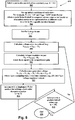
- Fig. 6 depicts an exemplary flow chart for the overall process in an exemplary embodiment and is generally indicated by numeral 400.
- the first step ⁇ 401> involves the building up of the generator voltage to a predetermined value, e.g., 0.9 p.u.
- the second step ⁇ 403> is for the system to measure the system step response of the generator.
- the system step response is measured by increasing the voltage reference by predetermined percentage, e.g., five percent (5%), and measuring the generator voltages during a first predetermined time period, e.g., every fifty (50) milliseconds.
- This process is repeated in the third step ⁇ 405> for a second predetermined time period, e.g., five (5) seconds.
- the set of data measured is referred to as the actual system step response and is stored for later use in the PSO algorithm.
- the system estimates exciter time constants T e , and generator time constants T' do .
- a Particle Swarm Optimization algorithm is used to estimate the exciter time constants T e , and generator time constants T' do , as described in detail below with reference to Fig. 7 .
- the estimated the exciter time constants T e and generator time constants T' do from step ⁇ 405> are used to calculate PID gains.
- PID gains can be calculated using either pole-zero cancellation or pole-placement, as described in detail below.
- Fig. 7 depicts an exemplary, non-limiting algorithm for performing Particle Swarm Optimization (PSO) for estimating exciter and generator time constants.
- PSO Particle Swarm Optimization
- each simulated particle has an associated position x k and velocity v k .
- Each particle's position is preferably represented by a pair of exciter time constant values T e and generator time constant values T' do (solutions).
- the first step of the PSO algorithm includes utilizing the PID controller 340, as shown in Fig 10 , 5 . ⁇ 412>, to build-up the generator voltage at a predetermined value, e.g., 0.9 p.u.
- the PID controller with zero derivative gain KD i.e., a PI controller is utilized.
- a second step of performing a voltage step response by increasing voltage reference by a predetermined percentage, e.g., five percent (5%), sampling the generator voltages during a first predetermined time period, e.g., every 50 milliseconds, and then recording the history of the sampled generator voltages during a second predetermined time period, e.g., five second interval ⁇ 414>.
- a predetermined percentage e.g., five percent (5%
- sampling the generator voltages e.g., every 50 milliseconds
- a second predetermined time period e.g., five second interval ⁇ 414>.
- the third step ⁇ 416> includes initializing a plurality of particles with a random or pre-selected position.
- the fourth step ⁇ 418> is to calculate the model's step response with selected particle position (computation of generator voltage).
- the second step ⁇ 504> is to set-up the initial conditions of each state.
- the sensed generator voltage e.g., V T (1)
- V REF can be set to 0.95 times a scale factor.
- a scale factor is used in computer science when a real world set of numbers needs to be represented on a different scale in order to fit a specific number format.
- the third step ⁇ 506> is to set the k-stage equal to one to utilize the Euler method to solve the first order dynamic equation.
- the seventh step ⁇ 514> is to increment the value of k to implement the Euler method for solving a first order dynamic equation.
- a determination is then made as to whether k is equal to a predetermined value ⁇ 516>, e.g., 100. If the response to this query is positive, the process for step ⁇ 418> from Fig. 7 ends ⁇ 518>, and if the response to this query is negative, the process returns to the fourth step ⁇ 508> to repeat steps ⁇ 508> through ⁇ 516> until the predetermined value, e.g., 100, is reached.
- each particle's position is evaluated during each iteration of the particle swarm optimization ("PSO") algorithm.
- PSO particle swarm optimization
- a simulated step response is calculated and its results are compared with the actual system step response. Therefore, the fitness function J evaluates the quality of a solution (exciter and generator time constants) by evaluating the difference between the system's simulated step response and the actual system step response.
- the sixth step ⁇ 422> obtains the two best values of time constants of the exciter and the generator, where T e represents the exciter time constant and T' do represents the generator time constant.
- each particle also has an associated "personal best" value pbest k , which stores the best solution that the particular particle has found.
- the system stores a "global best" solution gbest, which represents the best solution found (so far) by any of the particles.
- the expression "rand(0,1)" represents a random number between zero and one.
- the seventh step ⁇ 424> is a query as to whether the maximum number of predetermined iterations has been reached. If the response to this query is positive, the particle swarm optimization ("PSO") loop is terminated ⁇ 426>. If the response to this query is negative, then the process returns to the fourth step ⁇ 418>, which is to calculate the model's step response with selected particle position (computation of generator voltage), as shown in detail in Fig. 8 . The fifth step ⁇ 420> and sixth step ⁇ 422> are then also repeated until the maximum number of predetermined iterations has been reached in the seventh step ⁇ 424> and the particle swarm optimization ("PSO") loop is terminated ⁇ 426>.
- PSO particle swarm optimization
- the overall system is shown in Fig. 9 and is generally indicated by numeral 600.
- the generator voltage reference V REF 602 is applied to get the system's actual response of the exciter and the generator with AVR for T e , and T' do where z k is the measured generator voltage 604.
- the generator voltage reference V REF 602 is applied to get the system's simulated step response for T e , and T' do where y k is the simulated generator voltage 606.
- These values are compared with the fitness function, e.g., J , 608.
- There is then an adjustment made using particle swarm optimization (“PSO") 610 where the best values are obtained and the particles position and velocity are updated as previously described above.
- PSO particle swarm optimization
- This parameter adjustment is then applied to the system's simulated step response for T e , and T' do where y k is the simulated generator voltage 606 for the modeling of the excitation control system 606.
- T D represents the derivative filter time constant.
- pole-zero cancellation forces the two zeros resulting from the PID controller to cancel the two poles of the plant.
- the placement of zeros is achieved via appropriate choice of controller gains.
- K D T do ′ T E ln 9 t r ⁇ K G
- pole placement is used to design the PID controller.
- the desired closed-loop pole locations are decided on the basis for meeting a transient response specification.
- the above equations are implemented with a PID controller using a voltage regulator developed for small size generator set. It consists of micro processor and signal conditioning circuits for generator voltage and PWM controlled regulator output.
- the generator voltage can be sampled with sixteen (16) bits resolution after anti-aliasing filters. The rms calculation of generator voltage can then be calculated on a predetermined period, e.g., every quarter cycle.
- the self-tuning algorithm can be updated on a predetermined time period, e.g., every 200 milliseconds.
- the voltage regulator estimates a set of desired PID gains based on estimated time constants.
- the amplitude of the regulator output is then adjusted to maintain the voltage regulation in a linear region, which is a predetermined percentage of the rated generator voltage, e.g., 80%. This adjusted amplitude of regulator output is obtained during calculation of the system gain K G .
- a personal computer (“PC") program can be implemented on any of a wide variety of processors.
- the following illustrative, but nonlimiting, functions that can be implemented in the software program include: basic diagnostic functions (wiring and metering calibration); estimate the loop gain of the closed loop with PI controller; estimate generator and exciter time constants using Recursive Least Squares ("RLS") or Particle Swarm Optimization (“PSO”); calculate PID controller gains using estimated time constants ( T e and T' do ); and step response with real-time monitoring.
- basic diagnostic functions wiring and metering calibration
- estimate the loop gain of the closed loop with PI controller estimate generator and exciter time constants using Recursive Least Squares ("RLS") or Particle Swarm Optimization (“PSO”
- RLS Recursive Least Squares
- PSO Particle Swarm Optimization
- This software program is able to determine PID gains based on rising time and estimated parameters (system gain and exciter/generator time constants) using either a pole-zero cancellation method or a pole placement design method.
- Fig. 10 illustrates a block diagram of an exemplary embodiment of the present invention with Recursive Least Squares ("RLS”) and is generally indicated by numeral 62.
- I/O (Input/Output) circuitry 66 provides the interface between a first processor 64 and the heavy equipment, i.e., a power source 70, an exciter 76 and a generator 78 (Exciter/Generator/Power Source).
- the I/O circuitry 66 includes a power switch 72 and an analog-to-digital (“AD”) converter 82.
- the power source 70 provides power input voltage V P 71 to the power switch 72.
- the power switch 72 is controlled by the first processor 64.
- a wide variety of computing devices may be utilized for the first processor 64, e.g., computers, controllers, and so forth.
- a preferred embodiment for the first processor 64 includes an embedded microprocessor.
- the power switch 72 also provides exciter field voltage 74 to the field coils of the exciter 76.
- the exciter 76 provides power to the field coils of generator 78.
- the a.c. output voltage 80 of generator 78 is connected to the analog-to-digital (“AD") converter 82.
- the analog-to-digital (“AD”) converter 82 converts the input voltage level into a digital value which is passed on to the first processor 64. This digital value is then calculated 96, by the first processor 64, as a generator rms voltage, V T 98.
- the analog-to-digital (“AD") converter 82 could be contained within the first processor 64.
- the first processor 64 is loaded with a generator output voltage set point labelled V REF 102.
- the first processor 64 calculates the error 100 as the difference between the voltage set point V REF 102 and the sensed generator rms voltage, V T 98 from the analog-to-digital ("AD") converter 82.
- the first processor 64 is programmed to implement a PID controller 88.
- the first processor 64 is further programmed to calculate the estimated exciter time constant, i.e., T e , and the generator time constant, i.e., T' do , 94 as described above with input 96 involving the sensed generator rms voltage, V T 98.
- the voltage regulator output V R 90 from the PID controller 88 is summed 92 with a random input 86.
- This summation 92 is provided as input to both the power switch 72 as well as the calculations for the estimated exciter time constant, i.e., T e , and the generator time constant, i.e., T' do , 94.
- the first processor 64 is further programmed to calculate the PID gain values based on the estimated time constants, using either the pole-zero method or pole placement method as described above.
- the second processor 68 is connected to the first processor 64 through electronic communication link 84, e.g., RS 232 Communication Port.
- electronic communication links 84 e.g., RS 232 Communication Port.
- a variety of electronic communication protocols could be used, and RS 232 is merely one example.
- a wide variety of computing devices may be utilized for the second processor 68, e.g., computers, controllers, microprocessors and so forth.
- a preferred embodiment for the second processor 68 includes a general purpose microprocessor.
- the second processor 68 via the electronic communication link 84 allows the user of the second processor 68 to initiate the self-tuning mode, and to show on an electronic display 104 the estimated time constants and/or PID gain values. Any of a wide variety of electronic displays can suffice for the electronic display 104.
- second processor 68 can calculate the exciter and generator time constants and PID gain values, and communicate these values to the first processor 64.
- first processor 64 and the second processor 68 can be combined as a single processing mechanism and either embedded or located away from the exciter and generator.
- Fig. 11 illustrates a block diagram of an exemplary embodiment of the present invention with Particle Swarm Optimization (“PSO”) and is generally indicated by numeral 762.
- I/O (Input/Output) circuitry 766 provides the interface between a first processor 764 and the heavy equipment, i.e., a power source 768, an exciter 776 and a generator 778 (Exciter/Generator/Power Source).
- the I/O circuitry 766 includes a power switch 772 and an analog-to-digital (“AD”) converter 782.
- the power source 768 provides power input voltage V P 770 to the power switch 772.
- the power switch 772 is controlled by the first processor 764.
- a wide variety of computing devices may be utilized for the first processor 764, e.g., computers, controllers, and so forth.
- a preferred embodiment for the first processor 764 includes an embedded microprocessor.
- the power switch 772 also provides exciter field voltage 774 to the field coils of the exciter 776.
- the exciter 776 provides power to the field coils of generator 778.
- the a.c. output voltage 780 of generator 778 is connected to the analog-to-digital (“AD") converter 782.
- the analog-to-digital (“AD”) converter 782 converts the input voltage level into a digital value which is passed on to the first processor 764. This digital value is then calculated 784, by the first processor 764, as a generator rms voltage V T 786.
- the analog-to-digital (“AD") converter 782 could be contained within the first processor 764.
- the first processor 764 is loaded with a generator output voltage set point labelled V REF 788. There is a voltage step response by increasing voltage reference by a predetermined percentage, e.g., five percent (5%), sampling the generator voltages during a first predetermined time period, e.g., every 50 milliseconds, and then recording the history of the sampled generator voltages during a second predetermined time period, e.g., five second interval.
- This voltage step input ⁇ V 792 is summed 790 with the generator output voltage set point VR EF 788 and the generator rms voltage V T 786.
- This summation 790 is provided as input to a PID controller 789.
- the first processor 764 is programmed to implement a PID controller 789.
- the voltage regulator output V R 794 from the PID controller 789 is provided as input to the power switch 772.
- the second processor 824 that is connected to the first processor 764 through electronic communication link 798, e.g., RS 232 Communication Port.
- a variety of electronic communication protocols could be used, and RS 232 is merely one example.
- a wide variety of computing devices may be utilized for the second processor 824, e.g., computers, controllers, microprocessors and so forth.
- a preferred embodiment for the second processor 824 includes a general purpose computer.
- the set of data 800 involving generator rms voltage, V T and voltage step input ⁇ V is transmitted from the first processor 764 through electronic communication link 798 to the second processor 824.
- the calculated PID gain values 796 based on the estimated time constants, using either the pole-zero method or pole placement method as described above, is transmitted from the second processor 824 through electronic communication link 798 to the first processor 764.
- the voltage step input ⁇ V 802 is provided to create a simulation of step response with excitation control system models 806 that is compared against measured step response date from voltage regulator 804.
- This calculated generator rms voltage, V T 810 is compared against a measured generator rms voltage V T 808 with a comparator 812.
- the measured generator rms voltage V T 808 is the system's actual measured generator voltage of the exciter and the generator with a static load for T e and T' do and the calculated generator rms voltage V T 810 is the system's simulated generator voltage for T e and T' do .
- These PID gains with estimated values of generator time constant T' do and exciter time constant T e 818 are then provided to a control 820 that operates the self-tuning mode and provides status of the operation, including values of generator time constant T' do , exciter time constant T e and PID gains.
- This information can be provided to an electronic display 822 through an electrical conduit 826 from the control. 820.
- any of a wide variety of electronic displays may suffice for the electronic display 822, including, but not limited to: cathode ray tube ("CRT”); storage tube; bistable display; nixie tube display; vector display; flat panel display; vacuum fluorescent display (“VF”); light-emitting diode (“LED”) display; electroluminescent Display (“ELD”); plasma display panel (“PDP”); liquid crystal display (“LCD”); organic light-emitting diode displays (“OLED”); surface-conduction electron-emitter display (“SED”); laser optoelectronics; carbon nanotubes; and nanocrystal displays.
- CTR cathode ray tube
- storage tube bistable display
- nixie tube display vector display
- flat panel display vacuum fluorescent display
- LED light-emitting diode
- ELD electroluminescent Display
- PDP plasma display panel
- LCD liquid crystal display
- OLED organic light-emitting diode displays
- SED surface-conduction electron-emitter display
- performance of self-tuning algorithm is tested using the Diesel-Generating Set, which consists of a 75 kW, 208 Vac, 1800 RPM, 3 ⁇ synchronous generator.
- the excitation for this generator is provided by a permanent magnet generator ("PMG") excited 0.3 Amp, 7 Vdc, ac exciter at no load.
- PMG permanent magnet generator
- Evaluation of system performance begins by performing voltage step responses to examine the behavior of the excitation system connected to the generator.
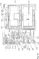
- a graphical user interface is generally indicated by numeral 200.
- This graphical user interface 200 appears on the electronic display 104, as shown in Fig. 10 .
- there are five modes which include: identifying loop gain K G 202; identifying time constants 204; stop identification 206; updating PID gains 208; and a software program exit function 210.
- For identifying loop gain 202 there is an input for identification of sampling time 212.
- For calculated PID there are four outputs that include: loop gain K G 218; proportional gain K P 220; integral gain K I 222; and derivative gain K D 224. Additional outputs include estimated time constants for the exciter T e 226 and the generator T' do 228. There are a series of inputs for creating graphical representations. These include a maximum value for the generator voltage on the y-axis 234; a minimum value for the generator voltage on the y-axis 236; a maximum value for the regulator voltage on the y-axis 230; and a minimum value for the regulator voltage on the y-axis 232.
- a graphical output icon 238 for extending a width of the x-axis and a graphical output icon 240 for reducing a width of the x-axis.
- a graphical output icon 240 for reducing a width of the x-axis.
- Fig. 13 is the same graphical user interface as shown in Fig. 12 with the exception of a graphical representation of a time constant for the exciter T e 252 and a graphical representation of a time constant for the generator T' do 254.
- the updating of the PID gains feature 208 is shown in detail in Fig. 14 and is generally indicated by numeral 260.
- There are five inputs for PID gains that include: loop gain K G 270; proportional gain K P 272; integral gain K I 274; derivative gain K D 276 and the derivative filter time constant T D 278.
- a push button icon 292 is used to increase the automatic voltage regulator to an upper predetermined value, e.g., 218.4, a push button icon 294 to operate the automatic voltage regulator at a nominal value and a push button icon 296 to decrease the automatic voltage regulator to a lower predetermined value, e.g., 197.6.
- a drop-down input 300 for a first graph is used to graph parameters on the Y-axis, e.g., generator voltage. There is an input for both a maximum value 302 and a minimum value 304. There is a drop-down input 306 for a second graph to graph parameters on the Y-axis 300, e.g., regulator voltage. There is an input for both a maximum value 308 and a minimum value 310.
- There is a graphical representation of generator voltage 244 and of regulator output 246 This is the automatic voltage regulator response utilizing default values, which indicates a large overshoot which is caused by improper gains.
- Fig. 15 is the same graphical user interface as shown in Fig. 14 with the exception that the graphical representation of generator voltage 322 and regulator output 324 reflects self-tuned PID gains that provide a fast response with no overshoot.
- the basic block diagram of a self-exciting excitation control system with exemplary PID block utilized in an automatic voltage regulator control loop is generally indicated by numeral 330.
- the system loop gain K G 338 provides an adjustable term to compensate for variations in system input voltage to a power converting bridge.
- the generator reference voltage V REF 332 is summed 336 with the summation 356 of the noise in the terminal voltage V N 352 with the sensed generator voltage V T 354 to form a voltage error signal.
- This voltage error signal is multiplied by the loop gain K G 338.
- This scaled voltage error signal is utilized to generate three terms with corresponding gains with the PID control 340, i.e., the proportional gain K P , the integral gain K I and the derivative gain K D .
- the output of the PID control 340 is multiplied 342 by the power input voltage V P 344 to create the voltage regulator output V R 350. For the external power input case, V P 344 becomes a constant. Therefore, a linear theory can be applied for small signal stability.
- the exciter field voltage is the output of the PID control 340 multiplied by the power input voltage V P 344.
- the excitation control system 330 becomes a bilinear system for the exciter and generator 348.
- a simple feedback linearization loop is implemented as shown in Fig. 16 and is generally indicated by numeral 360.
- the generator reference voltage V REF 332 is summed 362 with the output of the exciter and generator 348.
- the sensed voltage V C 368 is provided as output by the PID controller 340.
- the output of the exciter and generator 348 provides input to create an estimator of power input voltage V P 374.
- sampling time T SI 376 of the inner loop increases, a bilinear characteristic appears in the system response.
- An illustrative, but nonlimiting, value of sampling time would be fifty (50) milliseconds. The selection of 50 milliseconds has been determined based on the simulation results with time constants of the industrial excitation control system under a practical noise environment.
- the sensed voltage V C 368 is scaled 370 by the inverse of the power input voltage V P 342 to provide the voltage regulator output V R 350.
- the output of the exciter and generator 348 provides input to a transformer 372 that generates the power input voltage V P 342, which is then multiplied 378 by the voltage regulator output V R 350.
- G s K S 1 1 + s T e 1 1 + s T do '
- K S , T e , and T' do are the system gain, the exciter and generator time constants, respectively.
- the gain K G 338 in Fig. 5 is used for compensating variations in system configuration dependent gains such as power input voltage ( V P ) 344 and saturation effects, i.e., loop gain, i.e., K G , multiplied by the system gain, i.e., K S , is equal to one (1).
- the loop gain i.e., K G , 338 is estimated based on a steady state condition that is preferably near the rated generator voltage. This is preferably accomplished with a robust controller having a soft start feature.
- the soft start feature is preferably designed to avoid a large voltage overshoot during voltage buildup.
- the PID controller 340 is utilized to measure the voltage regulator output V R 350 and terminal voltage V T 354, as shown in Fig. 5 .
- the voltage regulator output V R 350 and terminal voltage V T 354 are measured in a steady-state condition of the closed loop with the PID controller 340.
- the steady-state condition is determined when the generator voltage variation is less than a predetermined value, e.g., 0.005 p.u., for more than a predetermined time period, e.g., ten (10) seconds.
- the regulator output and generator voltage are utilized to obtain the loop gain, i.e., K G , 338.
- a graphical user interface is generally indicated by numeral 1050.
- This graphical user interface 1050 appears on the electronic display 822, as shown in Fig. 11 .
- identifying loop gain K G 1002 there is an input for identification of gain factor 1012.
- identifying loop gain 1002 there is an input for identification of gain factor 1012.
- a click-on input 1014 for pole zero cancellation as a design method for a PID controller
- a click-on input 1016 for pole placement as a design method for a PID controller.
- For calculated PID there are four outputs that include: loop gain K G 1018; proportional gain K P 1020; integral gain K I 1022; and derivative gain K D 1024. Additional outputs include estimated time constants for the exciter T e 1026 and the generator T' do 1028. There are a series of inputs for creating graphical representations. These include a maximum value for the generator voltage on the y-axis 1034; a minimum value for the generator voltage on the y-axis 1036; a maximum value for the regulator voltage on the y-axis 1030; and a minimum value for the regulator voltage on the y-axis 1032.
- a graphical output icon 1038 for extending a width of the x-axis and a graphical output icon 1040 for reducing width of the x-axis.
- There is a graphical representation of generator voltage 1044 e.g., value of 0.740 volts
- regulator output 1046 e.g., value of 0.106 volts.
- a time constant for the exciter T e 1052 e.g., value of 0.294
- a time constant for the generator T' do 1054 e.g., value of 2.995.
- This software program monitors system and estimated parameters continuously.
- Fig. 18 Real-time monitoring feature was also implemented to easily evaluate system performance of the voltage step responses is shown in Fig. 18 , which is generally indicated by numeral 1120.
- PID gains that include: loop gain K G 1070; proportional gain K P 1072; integral gain K I 1074; derivative gain K D 1076 and the derivative filter time constant T D 1078.
- an indicator 1080 to indicate an alarm condition as well as an indicator 1098 of whether the automatic voltage regulator is either stopped or started.
- an indicator 1080 to indicate an alarm condition as well as an indicator 1098 of whether the automatic voltage regulator is either stopped or started.
- a push button icon 1092 is used to increase the automatic voltage regulator to an upper predetermined value, e.g., 210
- a push button icon 1094 to operate the automatic voltage regulator at a nominal value
- a push button icon 1096 to decrease the automatic voltage regulator to a lower predetermined value, e.g., 190.
- a drop-down input 1100 for a first graph is used to graph parameters on the Y-axis, e.g., generator voltage. There is an input for both a maximum value 1102 and a minimum value 1104. There is a drop-down input 1106 for a second graph to display parameters on the Y-axis, e.g., generator voltage. There is an input for both a maximum value 1108 and a minimum value 1110. There is a graphical output icon 1138 for extending a width of the x-axis and a graphical output icon 1140 for reducing width of the x-axis. There is also an input for a width of the x-axis in seconds 1142.
- regulator output voltage 1144 e.g., value of 0.040
- generator voltage 1146 e.g., value of 0.999. This is the automatic voltage regulator response utilizing default values, which indicates a large overshoot which is caused by improper gains.
- the external power input case (fixed power input voltage, i.e., V P ) is tested for comparison with a shunt application case.
- V P fixed power input voltage
- the results of two approaches are illustrated in the first table indicated by numeral 1202 for both a Recursive Least Square ("RLS") with linearization via feedback in comparison to the previously mentioned Particle Swarm Optimization (“PSO”) technique.
- RLS Recursive Least Square
- PSO Particle Swarm Optimization
- the second table is generally indicated by numeral 1204 for a shunt application for both a Recursive Least Square (“RLS”) with linearization via feedback in comparison to the previously mentioned Particle Swarm Optimization (“PSO”) technique. There is no significant error that is caused for the shunt application.
- RLS Recursive Least Square
- PSO Particle Swarm Optimization
- the estimation error in the PSO approach is mainly caused by the incorrect starting time to apply the unit input to the exciter field, which is determined randomly at a time delay.
- a nonlimiting example of this time delay is about sixteen (16) milliseconds.
- the random behavior is caused by inexact synchronization among the pulse width modulation ("PWM") signal update for the power amplifier, the rms calculation of 60 Hz voltage signal, and a real time interrupt time for control functions in the digital voltage regulator.
- PWM pulse width modulation
- performance of self-tuning algorithm is tested using the Diesel-Generating Set, which consists of a 75 kW, 208 Vac, 1800 RPM, 3 Phase synchronous generator.
- the excitation for this generator is provided by a permanent magnet generator ("PMG") excited 0.3 Amp, 7 Vdc, ac exciter at no load.
- PMG permanent magnet generator
- Evaluation of system performance begins by performing voltage step responses to examine the behavior of the excitation system connected to the generator.
- An automatic voltage regulator uses default values is shown in Fig. 21 , which is generally indicated by numeral 1220.
- There are five inputs for PID gains that include: loop gain K G 1230; proportional gain K P 1232; integral gain K I 1234; derivative gain K D 1236 and the derivative filter time constant T D 1238.
- a push button icon 1252 is used to increase the automatic voltage regulator to an upper predetermined value, e.g., 210, a push button icon 1254 to operate the automatic voltage regulator at a nominal value and a push button icon 1256 to decrease the automatic voltage regulator to a lower predetermined value, e.g., 190.
- a drop-down input 1258 for a first graph is used to graph parameters on the Y-axis, e.g., regulator output. There is an input for both a maximum value 1260 and a minimum value 1262. There is a drop-down input 1264 for a second graph to display parameters on the Y-axis, e.g., generator voltage. There is an input for both a maximum value 1266 and a minimum value 1268. There is a graphical output icon 1270 for extending a width of the x-axis and a graphical output icon 1272 for reducing width of the x-axis. There is also an input for a width of the x-axis in seconds 1274.
- regulator output 1276 e.g., value of 0.031
- generator voltage 1278 e.g. 0.999. This is the automatic voltage regulator response utilizing default values, which indicates a large overshoot which is caused by improper gains.
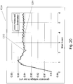
- the self-tuning PID gains are shown in Fig. 22 , which is generally indicated by numeral 1320.
- a push button icon 1352 is used to increase the automatic voltage regulator to an upper predetermined value, e.g., 210, a push button icon 1354 to operate the automatic voltage regulator at a nominal value and a push button icon 1356 to decrease the automatic voltage regulator to a lower predetermined value, e.g., 190.
- a drop-down input 1358 for a first graph is used to graph parameters on the Y-axis, e.g., regulator output. There is an input for both a maximum value 1360 and a minimum value 1362. There is a drop-down input 1364 for a second graph to display parameters on the Y-axis, e.g., generator voltage. There is an input for both a maximum value 1366 and a minimum value 1368. There is a graphical output icon 1370 for extending a width of the x-axis and a graphical output icon 1372 for reducing a width of the x-axis. There is also an input for a width of the x-axis in seconds 1374. There is a graphical representation of regulator output 1376, e.g., value of 0.040, and of generator voltage 1378, e.g., value of 0.999. This is the response utilizing self-tuning PID gains.
- the voltage step response of the first method using the automatic voltage regulator (“AVR”) with default values is shown by numerals 1276 and 1278 in Fig. 21 , is compared to self-tuning PID gains shown by numerals 1376 and 1378 in Fig. 22 .
- the automatic voltage regulator (“AVR") with default values is shown by numerals 1276 and 1278 in Fig. 21 indicates a large overshoot with improper gains.
- the self-tuning PID gains, shown by numerals 1376 and 1378 in Fig. 22 provide a response with much less overshoot.
- the large overshoot in step up response is caused by asymmetric high forcing limit. This is a typical response for a rotary excitation control system which has no negative field forcing. For this case, the selection of proper controller gains is more important.
- Fig. 23 The self-tuning PID gains for a medium level of generator set with a gas turbine and generator rated at 13.8 kV and 15 MVA, respectively, is shown in Fig. 23 , which is generally indicated by numeral 1420.
- a push button icon 1452 is used to increase the automatic voltage regulator to an upper predetermined value, e.g., 14,161.581 Volts, a push button icon 1454 to operate the automatic voltage regulator at a nominal value and a push button icon 1456 to decrease the automatic voltage regulator to a lower predetermined value, e.g., 12,812.859 Volts.
- a drop-down input 1458 for a first graph is used to graph parameters on the Y-axis, e.g., generator voltage. There is an input for both a maximum value 1460 and a minimum value 1462. There is a drop-down input 1464 for a second graph to display parameters on the Y-axis, e.g., regulator output. There is an input for both a maximum value 1466 and a minimum value 1468. There is a graphical output icon 1470 for extending a width of the x-axis and a graphical output icon 1472 for reducing a width of the x-axis. There is also an input for a width of the x-axis in seconds 1474. There is a graphical representation of generator voltage 1476, e.g., value of .977, and of regulator output 1478, e.g., value of 0.051. This is the response utilizing self-tuning PID gains.
- PSO Particle Swarm Optimization
- RLS Recursive Least Square
- PSO Particle Swarm Optimization
- RLS Recursive Least Square
Landscapes
- Engineering & Computer Science (AREA)
- Physics & Mathematics (AREA)
- General Physics & Mathematics (AREA)
- Automation & Control Theory (AREA)
- Computer Vision & Pattern Recognition (AREA)
- Artificial Intelligence (AREA)
- Health & Medical Sciences (AREA)
- Evolutionary Computation (AREA)
- Medical Informatics (AREA)
- Software Systems (AREA)
- Power Engineering (AREA)
- Control Of Eletrric Generators (AREA)
- Feedback Control In General (AREA)
Description
- This International Patent Application claims priority to
U.S. Patent Application Serial Number 12/183,781, filed July 31, 2008U.S. Patent .Application Serial Number 12/023,145, filed January 31, 2008 - An electrical generator typically operates by rotating a coil of wire relative to a magnetic field (or vice versa). In modern electrical generators, this magnetic field is typically generated using electromagnets known as field coils. An electrical current in these field coils provides the magnetic field necessary to induce an electrical current in the main generator coil. The current and voltage output of the main generator depends on the current in the field coils. Thus, as the generator load changes, the magnetic field strength must be adjusted in an attempt to maintain constant generator output. This is achieved by regulating the current in the field coils. Thus, it is desirable to regulate continuously the current in the field coils.
- In many modern electrical generators, the electrical current in the field coils is provided by an exciter generator. Thus, the problem of regulating the main generator field strength is typically achieved by regulating the output of the exciter generator. The exciter generator can include its own exciter field coils, in which case the output of the exciter generator can be controlled by regulating the current supplied to the exciter field coils.
- The output of a voltage regulator can provide power to the field coils of an exciter or generator. The voltage regulator can therefore be used to control the output of an exciter generator, and thereby control the output of a main generator. One important purpose of a voltage regulator is to maintain the output of a main generator at a constant voltage, known as the "set point," under various conditions. The difference between the set point and the actual main generator output is "error."
- Many different types of voltage regulators have been proposed for excitation systems. One of the most popular modern voltage regulator systems utilizes a Proportional, Integral, and Derivative ("PID") controller. A PID controller monitors the output of the generator and adjusts its own output depending on sensed generator output. As the name implies, the PID controller provides three types of control: proportional, integral, and derivative. Proportional control responds in proportion to the error. Integral control responds to the sum of previous errors. Derivative control responds to the rate of change of the error.
- Referring now to
Fig. 1 , the basic block diagram of a PID block utilized in the automatic voltage regulator control loop is generally indicated bynumeral 10. In addition to thePID block 10, the system loop gain KG provides an adjustable term to compensate for variations in system input voltage to a power converting bridge. The transfer function Gc(s) of the PID controller may be expressed as
- The generator
reference voltage V REF 12 is summed 16 with thesensed voltage V C 14 to form a voltage error signal. It is multiplied by theloop gain K G 18. This scaled voltage error signal is utilized to generate three terms with corresponding gains, theproportional gain K P 20, theintegral gain K I 22 and thederivative gain K D 24. The integral term is limited by an upper summation value of maxfield forcing V RLMT 26 divided by powerinput voltage V P 28. The integral term and the derivative term are summed together 30 and then this summation is summed 32 with the proportional term. Thissummed value 32 is multiplied by the powerinput voltage V P 34 to provide the voltageregulator output V R 36. - The relative weights of these three types of control in a PID controller must be set for accurate control of the generator output. Choosing these relative weights is known as "tuning" the PID controller. The goal is to achieve a "fast" excitation system that will respond to a disturbance by quickly bringing the generator output back to the set point. An ideal excitation system achieves the set point with as little overshoot and undershoot as possible. Overshoot occurs when the controller provides too much current, thereby causing a "spike" in main generator output. Undershoot occurs when the controller provides too little current, thereby causing a "dip" in main generator output. A poorly tuned PID controller will result in poor performance, e.g., overshoot, undershoot, or slow response time. A well-tuned excitation system offers benefits in overall operating performance by responding quickly to transient conditions such as system faults, disturbances, and motor starting. After a fault, a fast excitation system will improve transient stability by holding up the system voltage and providing positive damping to system oscillations. A well-tuned excitation system will minimize voltage overshoot after a disturbance and avoid the nuisance tripping of generator protection circuits. When a motor is powered by a generator, the motor presents a large load while the motor is starting, which can cause the generator output voltage to dip. A dip in generator output voltage can cause damage to the motor as the motor will increase its current consumption and heats up due to resistive heating within the motor. During motor starting, a fast excitation system will minimize the generator voltage dip and reduce the heating losses of the motor.
- The controller gains are determined using several excitation system parameters, such as voltage loop gain, open circuit time constants, and so forth. These parameters vary not only with the system loading conditions, as generally illustrated by
numeral 38 inFig. 2 , but also system configuration dependent gains such as power input voltage. - In general, since the calculation of loop gain requires several excitation system parameters that are generally not available during commissioning, e.g., specifically the machine time constant, this lack of information increases commissioning time. Many times there is no access to the actual equipment but only to a manufacturer's data sheet, or some typical data set. For this case, the only available measurement to check excitation system performance is the combined response of exciter and generator as generally illustrated by
numeral 40 inFig. 3 . Under these conditions, commissioning a new voltage regulator becomes a challenging task. - One method of tuning the PID controller is by trial-and-error. Trial-and-error is tedious and adds significantly to commissioning time. Consequently, several automatic "self-tuning" algorithms have been proposed.
- One difficulty in regulating the voltage output of a generator arises due to the inductive properties of a coil of wire, such as a field coil winding. Since the excitation system and the generator contain inductive coils, there is a time delay between a change in output voltage from the voltage regulator and the corresponding change in generator output voltage. The length of this delay is determined by "time constant." The main time constants of concern are the exciter time constant and the generator time constant. In the present invention, these time constants are estimated and taken into account when tuning the PID controller, thereby achieving improved performance.
- Also, today's digital voltage regulators are designed to achieve about 0.25% regulation accuracy at rated voltage. The accuracy of a digital voltage regulator is mostly determined by truncation error in an analog/digital ("AD") converter and thermal noise in interface circuits. Institute of Electrical and Electronics Engineers, Inc. ("I.E.E.E.") Standard 421.5 recommends two percent (2%) step responses for testing or analyzing performance of an excitation control loop. Thus, generator voltages due to small perturbation in excitation are measured with a very poor signal-to-noise ratio. For example, the relative accuracy of a two percent (2%) step response test becomes about a ten percent (10%) error in measurement. Therefore, in this case, it is difficult to identify the exciter and generator time constants. Experiments show very slow convergence speed in identification, which is much slower than today's fast excitation system requirements.
- The present invention is directed to overcoming one or more of the problems set forth above.
- It is described an automatic algorithm for tuning a PID controller using a Recursive Least Square algorithm with a forgetting factor. A new algorithm for estimating exciter and generator time constants is disclosed herein.
- In one embodiment, the calculated PID gains are fixed during commissioning. No further tuning is conducted during normal operation. The benefit of this approach is that no supervision is needed to prevent undesirable responses caused by a transient behavior of the PID gain estimation.
- In an embodiment, a system for self-tuning a PID controller utilized with an exciter and generator is disclosed. The system includes a power source, an exciter electrically connected to the power source, a generator that is electrically energized by the exciter, and a processor that provides a PID controller that calculates system gain, an estimated exciter time constant and an estimated generator time constant using a recursive least square with forgetting factor algorithm, wherein the estimated exciter time constant and the estimated generator time constant are utilized to calculate PID gains by the processor.
- In another embodiment, a system for self-tuning a PID controller utilized with an exciter and generator is disclosed. The system includes a power source, an exciter electrically connected to the power source, a generator that is electrically energized by the exciter, and a processor that provides a PID controller that calculates system gain, an estimated exciter time constant and an estimated generator time constant with a recursive least square with forgetting factor algorithm, wherein the estimated exciter time constant and the estimated generator time constant are utilized to calculate PID gains by the processor, wherein the processor includes a random input generator that is summed with the output of the PID controller as input to determine the PID gains using the estimated exciter time constant and the estimated generator time constant and the processor compares a digital value of rms generator voltage against a reference voltage as input into the PID controller.
- In yet another embodiment, a system for self-tuning a PID controller utilized with an exciter and generator is disclosed. The system includes a power source, an exciter electrically connected to the power source, a generator that is electrically energized by the exciter, a first processor that provides a PID controller that calculates system gain, an estimated exciter time constant and an estimated generator time constant with a recursive least square with forgetting factor algorithm, wherein the estimated exciter time constant and the estimated generator time constant are utilized to calculate PID gains by the first processor, wherein the processor includes a random input generator that is summed with the output of the PID controller as input to determine the PID gains using the estimated exciter time constant and the estimated generator time constant and the first processor compares a digital value of rms generator voltage against a reference voltage as input into the PID controller, a second processor controls a self-tuning mode and obtains operating status while obtaining the estimated exciter time constant, the estimated generator time constant and the PID gains from the first processor through a communications link, and an electronic display that is electrically connected to the second processor for displaying at least one of the operating status, diagnostic functions, the system gain, the estimated exciter time constant, the estimated generator time constant, and a step response with real time monitoring.
- In still yet another embodiment, a method for self-tuning a PID controller utilized with an exciter and generator is disclosed. The method includes calculating system gain with a processor that also operates as a PID controller, calculating an estimated exciter time constant and an estimated generator time constant with a recursive least square with forgetting factor algorithm with the processor, utilizing the estimated exciter time constant and the estimated generator time constant to calculate PID gains with the processor, self-tuning the PID gains, with the processor, to control exciter field voltage to an exciter, wherein the exciter electrically connected to the power source and a generator is electrically energized by the exciter.
- In another embodiment, a method for self-tuning a PID controller, utilized with an exciter and generator is disclosed. The method includes calculating system gain with a first processor that also operates as a PID controller, calculating an estimated exciter time constant and an estimated generator time constant with a recursive least square with forgetting factor algorithm with the first processor, utilizing the estimated exciter time constant and the estimated generator time constant to calculate PID gains with the first processor, self-tuning the PID gains, with the first processor, to control exciter field voltage to an exciter, wherein the exciter electrically connected to the power source and a generator is electrically energized by the exciter, controlling a self-tuning mode and obtaining operating status while obtaining the estimated exciter time constant, the estimated generator time constant and the PID gains from the first processor through a communications link with a second processor, and displaying at least one of the operating status, diagnostic functions, the system gain, the estimated exciter time constant, the estimated generator time constant, and a step response with real time monitoring on an electronic display that is electrically connected to the second processor.
- An embodiment of the present invention relates to an automatic algorithm for tuning a PID controller using a Particle Swarm Optimization (PSO) technique.
- In another embodiment, the PSO technique is used to estimate time constants for an exciter and generator in an excitation system.
- In still another embodiment, the estimated exciter and generator time constants are used to calculate PID gains (proportional gain KP, integral gain KI and derivative gain KD).
- In yet another embodiment, the calculated PID gains are fixed during commissioning. Preferably, no further tuning is conducted during normal operation. One benefit of this approach is that no supervision is needed to prevent undesirable responses caused by a transient behavior of the PID gain estimation.
- In still yet another embodiment, a system for self-tuning a PID controller utilized with an exciter and generator is disclosed. The system includes a power source, an exciter electrically connected to the power source, a generator that is electrically energized by the exciter, and a processor that provides a PID controller that calculates an estimated exciter time constant and an estimated generator time constant using particle swarm optimization to control exciter field voltage.
- In another embodiment, a system for self-tuning a PID controller utilized with an exciter and generator is disclosed. The system includes a power source, an exciter electrically connected to the power source, a generator that is electrically energized by the exciter, and a processor that provides a PID controller that performs a system step response by increasing the voltage reference by a predetermined percentage over a predetermined time period, initializes each particle position of exciter time constant and generator time constant, calculates generator voltage, performs a fitness evaluation and then obtains and updates best values and then repeats calculating the generator voltage, the fitness evaluation and the best values over a predetermined number of iterations.
- In yet another embodiment, a system for self-tuning a PID controller utilized with an exciter and generator is disclosed. The system includes a power source, an exciter electrically connected to the power source, a generator that is electrically energized by the exciter, a first processor that provides a PID controller with a combination of a reference voltage, a system step response by increasing the voltage reference by a predetermined percentage over a predetermined time period and a calculated generator voltage, and a second processor that receives the system step response and the calculated generator voltage through a communications link and then compares a simulation of a step response using the system step response and measured step response from a voltage regulator and then performs an adjustment using particle swarm optimization which is then provided to the simulation of a step response and also utilized in calculating an estimated exciter time constant, an estimated generator time constant, and PID gains, which are then provided through the communications link to the first processor, wherein the second processor controls a self-tuning mode and obtains operating status, which includes at least one of the estimated exciter time constant, the estimated generator time constant and the PID gains, and an electronic display that is electrically connected to the second processor for displaying at least one of the operating status, a diagnostic function, the estimated exciter time constant, the estimated generator time constant and the PID gains with real time monitoring.
- In still yet another embodiment, a method for self-tuning a PID controller utilized with an exciter and generator is disclosed. The method includes calculating an estimated exciter time constant and an estimated generator time constant with particle swarm optimization with a processor that provides a PID controller, and utilizing the estimated exciter time constant and the estimated generator time constant to calculate PID gains with the processor to control exciter field voltage to an exciter, wherein the exciter electrically connected to the power source and a generator is electrically energized by the exciter.
- These are merely some of the innumerable aspects of the present invention and should not be deemed an all-inclusive listing of the innumerable aspects associated with the present invention.
- Thus, the prior art provides technical background for this disclosure. "A Particle Swarm Optimization Approach for Optimum Design of PID Controller in AVR System", IEEE Trans. Energy Convers., Vol. 19 No. 2, June 2004, by Zwe-Lee Gaing discloses a Particle Swarm Optimization Approach for optimizing three controller parameters of a PID controller in a voltage regulator, based on linearized models of a PID controller, an amplifier, an exciter, a generator, and a sensor, based on various time-domain performance criteria. "Nonlinear Identification and Control of a Turbogenerator - An On-Line Scheduled Multiple Model/Controller Approach", IEEE Trans. Energy Convers., Vol. 20 No. 1, March 2005, by Ren Lixin, George Irwin, and Damian Flynn, discloses an approach for the design of an AVR, including multiple PID controllers, for non-linear control of the terminal output of a turbogenerator, by regulating the excitation field of the turbogenerator. Each of these two references of Gaing and Flynn et al, show the need for a system / method, such as that disclosed herein.
- For a better understanding of the present invention, reference may be made to accompanying drawings, in which:
-
Fig. 1 depicts a block diagram representation of a PID controller utilized in an automatic voltage regulator; -
Fig. 2 is a graphical representation of a generator saturation curve illustrating generator gain; -
Fig. 3 is a graphical representation of a phase shift in degrees for an exciter field, a generator field, and the summation of the phase shift for the exciter field and the generator field in relationship to machine/regulator oscillating frequency; -
Fig. 4 depicts a block diagram representation for an estimation algorithm that relies on both exciter and generator dynamics; -
Fig. 5 depicts a block diagram representation of a simplified excitation control system with automatic voltage regulators; -
Fig. 6 is a flowchart for the overall process of an exemplary embodiment for calculating PID gains; -
Fig. 7 is a flowchart for an estimation algorithm based on Particle Swarm Optimization (PSO); -
Fig. 8 is a detailed analysis for the step of calculating a model's step response with selected particle position (computation of generator voltage), i.e., process step <418>, fromFig. 7 ; -
Fig. 9 depicts a block diagram representation for identification utilizing Particle Swarm Optimization (PSO); -
Fig. 10 shows a block diagram of an exemplary embodiment of the present invention utilizing at least one processor, input/output, an exciter, a generator and an associated power supply; -
Fig. 11 shows a block diagram of an exemplary embodiment of the present invention utilizing at least one processor, input/output, an exciter, a generator and an associated power supply; -
Fig. 12 is a graphical user interface showing estimation of loop gain; -
Fig. 13 is a graphical user interface showing estimation of time constants; -
Fig. 14 is a graphical user interface showing an automatic voltage regulator response with default values; -
Fig. 15 is a graphical user interface showing self-tuned PID gains; -
Fig. 16 depicts a block diagram representation for feedback linearization of a self-excitation control system; -
Fig. 17 is a graphical user interface showing estimation of time constants; -
Fig. 18 is a graphical user interface showing a step response with calculated PID gains; -
Fig. 19 is a comparison of time constants, i.e., T'do and Te, for the Recursive Least Square ("RLS") with linearization via feedback in comparison to Particle Swarm Optimization ("PSO") technique with an external power input, for a self-excited power input; and a shunt case with noise, i.e., 10% relative error in generator voltage; -
Fig. 20 is a graphical comparison of measured versus estimated response for the Particle Swarm Optimization ("PSO") technique for generator voltage over time; -
Fig. 21 is a graphical user interface showing an automatic voltage regulator response with default values; -
Fig. 22 is a graphical user interface showing self-tuned PID gains; and -
Fig. 23 is a graphical user interface showing the step response of a gas turbine generator set. - In the following detailed description, numerous exemplary specific details are set forth in order to provide a thorough understanding of the invention. However, it will be understood by those skilled in the art that the present invention may be practiced without these specific details, or with various modifications of the details. In other instances, well known methods, procedures, and components have not been described in detail so as not to obscure the present invention.
- A self-tuning recursive least squares algorithm is represented as follows:
- KS represents the system gain.
- TE represents the exciter time constant.
- T'do represents the generator time constant.
- The plant transfer function G(s) can then be expressed as:

- When y(k) represents the generator output voltage at time sample k and u(k) represents the regulator output voltage at time sample k then the generator output can be expressed in a discrete form as:

- In recursive least square estimation, unknown parameters of a linear model are chosen in such a way that the sum of the squared errors between actually observed and computed generator voltage (y(k)) is at a minimum.
- When α = [a 1 a 2 b 1 B 2 1] and φT (k) = [y(k -1) y(k - 2) u(k - 1) u(k - 2) 1] then:


- Referring now to
Fig. 4 , a block diagram of the Recursive Least Squares scheme is generally indicated bynumeral 42. The closed loop control system with a proportional ("P")gain controller 48 is utilized. This provides for stable operation in the linear region rather than the saturation region. Arandom input 52 is provided which operates as a disturbance is summed 54 with the controllervoltage output V C 50 from the proportional ("P")gain controller 48. Thissummation 54 is provided as input to calculate the values of the exciter time constant, i.e., Te, and the generator time constant, i.e., T'do 60. Also,summation 54 is provided to the linearized exciter andgenerator 58. The generator terminal voltage from the exciter andgenerator 58 is also provided as input to calculate the values of the exciter time constant, i.e., Te, and the generator time constant, i.e., T'do 60. The generator terminal voltage from the exciter andgenerator 58 is also summed 46 with generator voltage Reference ("VREF") 44 that provides input to the proportional gain ("P")gain controller 48. The proportional gain is selected at a predetermined value, e.g., eight (8) p.u. to regulate at eighty five percent (85%) of rated voltage. - The next step is to calculate system gain. If VR represents the output voltage of the PID and VT represents the generator output voltage then the steps for calculating the system loop gain KG are:
- 1. check residual voltage with zero regulator output;
- 2. find open loop output corresponding to residual voltage;
- 3. find regulator output corresponding to nominal generator voltage; and
- 4. calculate loop gain according to the following equation: KG = VR / VT
- The exciter and generator time constants are then calculated. The generator time constant (T'do ) is calculated based on estimated parameters, αk1 and αk2, obtained by Recursive Least Squares according to the following equation:

- The exciter time constant T'do is calculated based on estimated parameters, αk1 and αk2, obtained by Recursive Least Squares according to the following equation:
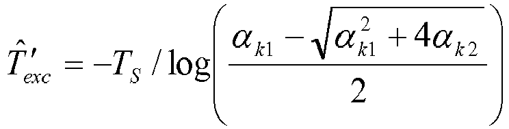
- Another method for estimating time constants includes Particle Swarm Optimization (PSO). Particle Swarm Optimization (PSO) is a technique that can be used to estimate PID gain values (the proportional gain KP, the integral gain KI and the derivative gain KD ). PSO is an evolutionary computation technique and is inspired by social behavior of birds flocking or fish schooling. The system is initialized with a population of random solutions and searches for optima by updating generations. The PSO technique mimics behaviors found in nature. The idea is to search a solution space using a "swarm" of simulated individuals or "particles." Each particle has a position in the search space, where each position corresponds to one possible solution to the problem. Each particle has an associated velocity vector. Each particle flies in the search space according to specified rules. These rules, for example, can include: (1) each particle remembers its own personal best solution found so far (pbest); (2) each particle is aware of the global best solution found so far all particles in the swarm (gbest); (3) each particle is programmed to move toward its personal best (pbest) location(s); and (4) each particle is programmed to move toward the global best (gbest) location(s).
- Typically, each particle moves once per iteration, and the program is executed over a pre-determined number of iterations. Each particle's position is evaluated according to a "fitness function," which determines the desirability of that solution. Once the software program has reached the iteration limit, the best values found so far are used as the estimated optimal values.
- Based on an estimated value of system gain, i.e., Ks, the system parameter is normalized in per unit. A simple feedback linearization loop is constructed to eliminate bilinear system characteristics that may be present in the system shown in
Fig. 16 . Overall, for simulation of the system, the Euler integration method is utilized for solving ordinary differential equations of dynamic models with an integration step size of a predetermined value, e.g., ten (10) milliseconds. Therefore, the power input is estimated for every predetermined time period, e.g., ten milliseconds, and the controller output is scaled by the power input voltage to eliminate a bilinear effect. - In the description of the flowcharts, the functional explanation marked with numerals in angle brackets <nnn>, will refer to the flowchart blocks bearing that numeral.
Fig. 6 depicts an exemplary flow chart for the overall process in an exemplary embodiment and is generally indicated bynumeral 400. The first step <401> involves the building up of the generator voltage to a predetermined value, e.g., 0.9 p.u. The second step <403> is for the system to measure the system step response of the generator. Preferably, the system step response is measured by increasing the voltage reference by predetermined percentage, e.g., five percent (5%), and measuring the generator voltages during a first predetermined time period, e.g., every fifty (50) milliseconds. This process is repeated in the third step <405> for a second predetermined time period, e.g., five (5) seconds. - The set of data measured is referred to as the actual system step response and is stored for later use in the PSO algorithm. In the fourth step <407>, the system estimates exciter time constants Te, and generator time constants T'do. Preferably, a Particle Swarm Optimization algorithm is used to estimate the exciter time constants Te, and generator time constants T'do, as described in detail below with reference to
Fig. 7 . Finally, at the fifth step <409>, the estimated the exciter time constants Te and generator time constants T'do from step <405> are used to calculate PID gains. PID gains can be calculated using either pole-zero cancellation or pole-placement, as described in detail below. -
Fig. 7 depicts an exemplary, non-limiting algorithm for performing Particle Swarm Optimization (PSO) for estimating exciter and generator time constants. Preferably, each simulated particle has an associated position xk and velocity vk . Each particle's position is preferably represented by a pair of exciter time constant values Te and generator time constant values T'do (solutions). The "kth" particle's position can be represented as follows: xk = (T'do,Te ) where T'do represents the generator time constant and Te represents the exciter time constant. - In the exemplary flow chart shown in Fig. 137 and indicated generally by
numeral 410, the first step of the PSO algorithm includes utilizing thePID controller 340, as shown inFig 10 ,5 . <412>, to build-up the generator voltage at a predetermined value, e.g., 0.9 p.u. For this purpose, the PID controller with zero derivative gain KD, i.e., a PI controller is utilized. This is followed by a second step of performing a voltage step response by increasing voltage reference by a predetermined percentage, e.g., five percent (5%), sampling the generator voltages during a first predetermined time period, e.g., every 50 milliseconds, and then recording the history of the sampled generator voltages during a second predetermined time period, e.g., five second interval <414>. This is a set of recorded data ZT (k) when k goes from one to a predetermined value, e.g., k = 1, ..., 100. - This set of data for the actual system step response can also be termed a reference response. The third step <416> includes initializing a plurality of particles with a random or pre-selected position. For example, one possible pre-selected initialization of particles (Te , T'do ) could be: x 1 =(1.0,0.1), x 2 =(2.0,0.2), x 3 =(3.0,0.3), x 4 =(4.0,0.4) and x 5 = (5.0,0.5). The associated velocity for each particle (one through five) is preferably initialized at zero: vk =0 for k = 1...5 . This is based on the fact that in general, the exciter time constant is designed about one tenth of the generator time constant for most generator sets. By the same practical reason to simplify computations, the boundary of the search surface is constrained by the following rules: 0.5 ≤ T'do ≤ 10 and 0.1 ≤ Te ≤ 0.5T'do .
- The fourth step <418> is to calculate the model's step response with selected particle position (computation of generator voltage). As shown in detail in
Fig. 8 , the first step <502> is to select a particular particle (time constant). For example, T = 2.0. The second step <504> is to set-up the initial conditions of each state. For example, the sensed generator voltage, e.g., VT (1), can be set equal to 0.9 for 0.9 p.u. and the generator voltage reference VREF can set to 0.95 times a scale factor. A scale factor is used in computer science when a real world set of numbers needs to be represented on a different scale in order to fit a specific number format. - The third step <506> is to set the k-stage equal to one to utilize the Euler method to solve the first order dynamic equation. The fourth step <508> is to calculate the voltage error in a closed loop, which is the generator voltage reference minus the sensed generator voltage, i.e., VERROR = VREF - VT. The fifth step <510> is to calculate the voltage regulator output which is the generator voltage reference times the proportional gain, i.e., VR = V ERROR * KP. The sixth step <512> is to calculate a new generator voltage, i.e., VT (k) = VT (k) + TS * (VT (k) + VR ) /T, where TS is the sampling time, T is the time constant, e.g., 2.0, and VR is the voltage regulator output for the current value of k.
- The seventh step <514> is to increment the value of k to implement the Euler method for solving a first order dynamic equation. A determination is then made as to whether k is equal to a predetermined value <516>, e.g., 100. If the response to this query is positive, the process for step <418> from
Fig. 7 ends <518>, and if the response to this query is negative, the process returns to the fourth step <508> to repeat steps <508> through <516> until the predetermined value, e.g., 100, is reached. This provides a set of calculated data VT (k) when k goes from one to a predetermined value, e.g., k = 1, ..., 100. - Returning again to
Fig. 7 , the fifth step <420>, involves comparing the set of recorded data ZT (k) when k goes from one to a predetermined value, e.g., k = 1, ..., 100 from step <418> with the set of calculated data VT (k) when k goes from one to a predetermined value, e.g., k = 1,..., 100 from step <418> with the following exemplary "fitness function" J for evaluation of the quality of a particle's position is:
- The sixth step <422>, as shown in
Fig. 7 , obtains the two best values of time constants of the exciter and the generator, where Te represents the exciter time constant and T'do represents the generator time constant. Preferably, each particle also has an associated "personal best" value pbestk, which stores the best solution that the particular particle has found. Preferably, the system stores a "global best" solution gbest, which represents the best solution found (so far) by any of the particles. After obtaining the two best values of exciter time constant Te and generator time constant, T'do, the particle updates the particle's velocity and positions. - An exemplary formula for updating particle velocity is given as follows: v k+1 = αvk + β 1 rand(0,1)[pbestk - xk ] + β2rand(0,1)[gbest - xk ], where xk is the current particle position, α is an inertia weight, β1 is equal to a first learning factor and β2 is equal to a second learning factor. The expression "rand(0,1)" represents a random number between zero and one. An exemplary formula for updating particle position is given as follows: x k+1 = xk + vk , where xk is the current particle position and vk is the current particle velocity.
- The seventh step <424> is a query as to whether the maximum number of predetermined iterations has been reached. If the response to this query is positive, the particle swarm optimization ("PSO") loop is terminated <426>. If the response to this query is negative, then the process returns to the fourth step <418>, which is to calculate the model's step response with selected particle position (computation of generator voltage), as shown in detail in
Fig. 8 . The fifth step <420> and sixth step <422> are then also repeated until the maximum number of predetermined iterations has been reached in the seventh step <424> and the particle swarm optimization ("PSO") loop is terminated <426>. - In summary, the overall system is shown in
Fig. 9 and is generally indicated bynumeral 600. The generatorvoltage reference V REF 602 is applied to get the system's actual response of the exciter and the generator with AVR for Te, and T'do where zk is the measuredgenerator voltage 604. Also, the generatorvoltage reference V REF 602 is applied to get the system's simulated step response for Te, and T'do where yk is the simulated generator voltage 606. These values are compared with the fitness function, e.g., J, 608. There is then an adjustment made using particle swarm optimization ("PSO") 610 where the best values are obtained and the particles position and velocity are updated as previously described above. This parameter adjustment is then applied to the system's simulated step response for Te, and T'do where yk is the simulated generator voltage 606 for the modeling of the excitation control system 606. - Upon calculation of the system gain and the exciter and generator time constants, the PID gains can be calculated. TD represents the derivative filter time constant. To simplify the design of the PID controller, the following assumptions are made:


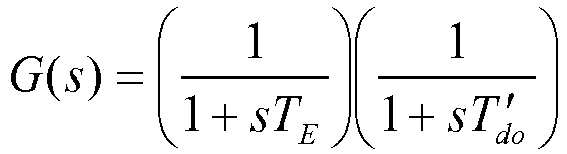
- There are two methods that can be utilized for designing the PID controller: (1) pole-zero cancellation; and (2) pole placement. In one embodiment of the present invention, pole-zero cancellation forces the two zeros resulting from the PID controller to cancel the two poles of the plant. The placement of zeros is achieved via appropriate choice of controller gains. The open-loop transfer function of the system becomes:

- For pole-zero cancellation:


- Thus the system transfer function is reduced to:


- The time response of the closed-loop system to a unit step input is as follows:


- In another embodiment of the present invention, pole placement is used to design the PID controller. In this method, the desired closed-loop pole locations are decided on the basis for meeting a transient response specification. In one embodiment, the design forces the overall closed-loop system to be a dominantly second-order system. Specifically, we force the two dominant closed-loop poles to be a complex conjugate pair, (s = -a ±jb) resulting in an underdamped response. The third pole is chosen to be a real pole (s = c), and is placed so that the natural mode of response from it is five times faster than the dominant poles. The open loop transfer function is given as:

- The PID controller gains KP, KI, and KD are then analytically determined by solving the characteristic equation:


- Thus, there are three equations and three unknowns. The value of s for each of Equations


- Preferably, but not necessarily, the above equations are implemented with a PID controller using a voltage regulator developed for small size generator set. It consists of micro processor and signal conditioning circuits for generator voltage and PWM controlled regulator output. Preferably, but not necessarily, the generator voltage can be sampled with sixteen (16) bits resolution after anti-aliasing filters. The rms calculation of generator voltage can then be calculated on a predetermined period, e.g., every quarter cycle. Moreover, the self-tuning algorithm can be updated on a predetermined time period, e.g., every 200 milliseconds. When the self-tuning mode is activated by the user, the voltage regulator estimates a set of desired PID gains based on estimated time constants. The amplitude of the regulator output is then adjusted to maintain the voltage regulation in a linear region, which is a predetermined percentage of the rated generator voltage, e.g., 80%. This adjusted amplitude of regulator output is obtained during calculation of the system gain KG.
- For a simple user interface to digital voltage regulator with self-tuning feature, a personal computer ("PC") program can be implemented on any of a wide variety of processors. The following illustrative, but nonlimiting, functions that can be implemented in the software program include: basic diagnostic functions (wiring and metering calibration); estimate the loop gain of the closed loop with PI controller; estimate generator and exciter time constants using Recursive Least Squares ("RLS") or Particle Swarm Optimization ("PSO"); calculate PID controller gains using estimated time constants (Te and T'do ); and step response with real-time monitoring.
- Therefore, a field engineer is able to activate a self-tuning mode utilizing this software program. This software program is able to determine PID gains based on rising time and estimated parameters (system gain and exciter/generator time constants) using either a pole-zero cancellation method or a pole placement design method.
-
Fig. 10 illustrates a block diagram of an exemplary embodiment of the present invention with Recursive Least Squares ("RLS") and is generally indicated bynumeral 62. I/O (Input/Output)circuitry 66 provides the interface between afirst processor 64 and the heavy equipment, i.e., apower source 70, anexciter 76 and a generator 78 (Exciter/Generator/Power Source). The I/O circuitry 66 includes apower switch 72 and an analog-to-digital ("AD")converter 82. Thepower source 70 provides powerinput voltage V P 71 to thepower switch 72. Thepower switch 72 is controlled by thefirst processor 64. A wide variety of computing devices may be utilized for thefirst processor 64, e.g., computers, controllers, and so forth. A preferred embodiment for thefirst processor 64 includes an embedded microprocessor. Thepower switch 72 also providesexciter field voltage 74 to the field coils of theexciter 76. Theexciter 76 provides power to the field coils ofgenerator 78. The a.c.output voltage 80 ofgenerator 78 is connected to the analog-to-digital ("AD")converter 82. The analog-to-digital ("AD")converter 82 converts the input voltage level into a digital value which is passed on to thefirst processor 64. This digital value is then calculated 96, by thefirst processor 64, as a generator rms voltage,V T 98. Optionally, the analog-to-digital ("AD")converter 82 could be contained within thefirst processor 64. - The
first processor 64 is loaded with a generator output voltage set point labelledV REF 102. Thefirst processor 64 calculates theerror 100 as the difference between the voltageset point V REF 102 and the sensed generator rms voltage,V T 98 from the analog-to-digital ("AD")converter 82. Thefirst processor 64 is programmed to implement aPID controller 88. Thefirst processor 64 is further programmed to calculate the estimated exciter time constant, i.e., Te, and the generator time constant, i.e., T'do, 94 as described above withinput 96 involving the sensed generator rms voltage,V T 98. The voltageregulator output V R 90 from thePID controller 88 is summed 92 with arandom input 86. Thissummation 92 is provided as input to both thepower switch 72 as well as the calculations for the estimated exciter time constant, i.e., Te, and the generator time constant, i.e., T'do, 94. Thefirst processor 64 is further programmed to calculate the PID gain values based on the estimated time constants, using either the pole-zero method or pole placement method as described above. - There is a
second processor 68 that is connected to thefirst processor 64 throughelectronic communication link 84, e.g.,RS 232 Communication Port. A variety of electronic communication protocols could be used, andRS 232 is merely one example. A wide variety of computing devices may be utilized for thesecond processor 68, e.g., computers, controllers, microprocessors and so forth. A preferred embodiment for thesecond processor 68 includes a general purpose microprocessor. Thesecond processor 68 via theelectronic communication link 84 allows the user of thesecond processor 68 to initiate the self-tuning mode, and to show on anelectronic display 104 the estimated time constants and/or PID gain values. Any of a wide variety of electronic displays can suffice for theelectronic display 104. Optionally,second processor 68 can calculate the exciter and generator time constants and PID gain values, and communicate these values to thefirst processor 64. However, both thefirst processor 64 and thesecond processor 68 can be combined as a single processing mechanism and either embedded or located away from the exciter and generator. -
Fig. 11 illustrates a block diagram of an exemplary embodiment of the present invention with Particle Swarm Optimization ("PSO") and is generally indicated bynumeral 762. I/O (Input/Output)circuitry 766 provides the interface between afirst processor 764 and the heavy equipment, i.e., apower source 768, anexciter 776 and a generator 778 (Exciter/Generator/Power Source). The I/O circuitry 766 includes apower switch 772 and an analog-to-digital ("AD")converter 782. Thepower source 768 provides powerinput voltage V P 770 to thepower switch 772. Thepower switch 772 is controlled by thefirst processor 764. A wide variety of computing devices may be utilized for thefirst processor 764, e.g., computers, controllers, and so forth. A preferred embodiment for thefirst processor 764 includes an embedded microprocessor. Thepower switch 772 also providesexciter field voltage 774 to the field coils of theexciter 776. Theexciter 776 provides power to the field coils ofgenerator 778. The a.c.output voltage 780 ofgenerator 778 is connected to the analog-to-digital ("AD")converter 782. The analog-to-digital ("AD")converter 782 converts the input voltage level into a digital value which is passed on to thefirst processor 764. This digital value is then calculated 784, by thefirst processor 764, as a generatorrms voltage V T 786. Optionally, the analog-to-digital ("AD")converter 782 could be contained within thefirst processor 764. - The
first processor 764 is loaded with a generator output voltage set point labelledV REF 788. There is a voltage step response by increasing voltage reference by a predetermined percentage, e.g., five percent (5%), sampling the generator voltages during a first predetermined time period, e.g., every 50 milliseconds, and then recording the history of the sampled generator voltages during a second predetermined time period, e.g., five second interval. This voltage step input ΔV 792 is summed 790 with the generator output voltage setpoint VR EF 788 and the generator rmsvoltage V T 786. Thissummation 790 is provided as input to aPID controller 789. Thefirst processor 764 is programmed to implement aPID controller 789. The voltageregulator output V R 794 from thePID controller 789 is provided as input to thepower switch 772. - There is a
second processor 824 that is connected to thefirst processor 764 throughelectronic communication link 798, e.g.,RS 232 Communication Port. A variety of electronic communication protocols could be used, andRS 232 is merely one example. A wide variety of computing devices may be utilized for thesecond processor 824, e.g., computers, controllers, microprocessors and so forth. A preferred embodiment for thesecond processor 824 includes a general purpose computer. The set ofdata 800 involving generator rms voltage, VT and voltage step input ΔV is transmitted from thefirst processor 764 throughelectronic communication link 798 to thesecond processor 824. The calculated PID gain values 796 based on the estimated time constants, using either the pole-zero method or pole placement method as described above, is transmitted from thesecond processor 824 throughelectronic communication link 798 to thefirst processor 764. - The voltage
step input ΔV 802 is provided to create a simulation of step response with excitationcontrol system models 806 that is compared against measured step response date fromvoltage regulator 804. This calculated generator rms voltage,V T 810 is compared against a measured generatorrms voltage V T 808 with acomparator 812. The measured generatorrms voltage V T 808 is the system's actual measured generator voltage of the exciter and the generator with a static load for Te and T'do and the calculated generatorrms voltage V T 810 is the system's simulated generator voltage for Te and T'do. These values are compared with the fitness function and then an adjustment is made using particle swarm optimization ("PSO") 814 where the best values are obtained and the particles position and velocity are updated as previously described above. The adjustment of the model parameters 814 xk = (T'do,Te ) where T'do represents the generator time constant and Te represents the exciter time constant is fed back into the simulation of step response with excitationcontrol system models 806. - The adjustment of the model parameters 814 xk = (T'do,Te ) is also then used to calculate the PID gain values based on the
estimated time constants 816, using either the pole-zero method or pole placement method as described above with calculations from thesecond processor 824. These PID gains with estimated values of generator time constant T'do and exciter timeconstant T e 818 are then provided to acontrol 820 that operates the self-tuning mode and provides status of the operation, including values of generator time constant T'do, exciter time constant Te and PID gains. This information can be provided to anelectronic display 822 through anelectrical conduit 826 from the control. 820. Any of a wide variety of electronic displays may suffice for theelectronic display 822, including, but not limited to: cathode ray tube ("CRT"); storage tube; bistable display; nixie tube display; vector display; flat panel display; vacuum fluorescent display ("VF"); light-emitting diode ("LED") display; electroluminescent Display ("ELD"); plasma display panel ("PDP"); liquid crystal display ("LCD"); organic light-emitting diode displays ("OLED"); surface-conduction electron-emitter display ("SED"); laser optoelectronics; carbon nanotubes; and nanocrystal displays. Both thefirst processor 764 and thesecond processor 824 can be combined as a single processing mechanism and either embedded or located away from the exciter and the generator. Any of a wide variety of computing mechanisms may suffice for either thefirst processor 764 or the second processor 724 - As an illustrative, but nonlimiting example, performance of self-tuning algorithm is tested using the Diesel-Generating Set, which consists of a 75 kW, 208 Vac, 1800 RPM, 3ϕ synchronous generator. The excitation for this generator is provided by a permanent magnet generator ("PMG") excited 0.3 Amp, 7 Vdc, ac exciter at no load. Evaluation of system performance begins by performing voltage step responses to examine the behavior of the excitation system connected to the generator.
- As shown in
Fig. 12 , a graphical user interface is generally indicated bynumeral 200. Thisgraphical user interface 200 appears on theelectronic display 104, as shown inFig. 10 . Referring again toFig. 12 , there are five modes which include: identifyingloop gain K G 202; identifyingtime constants 204; stopidentification 206; updatingPID gains 208; and a softwareprogram exit function 210. For identifyingloop gain 202, there is an input for identification of sampling time 212. There is a click-oninput 214 for pole zero cancellation as a design method for a PID controller and a click-oninput 216 for pole placement as a design method for a PID controller. - For calculated PID, there are four outputs that include:
loop gain K G 218;proportional gain K P 220;integral gain K I 222; andderivative gain K D 224. Additional outputs include estimated time constants for theexciter T e 226 and the generator T'do 228. There are a series of inputs for creating graphical representations. These include a maximum value for the generator voltage on the y-axis 234; a minimum value for the generator voltage on the y-axis 236; a maximum value for the regulator voltage on the y-axis 230; and a minimum value for the regulator voltage on the y-axis 232. There is agraphical output icon 238 for extending a width of the x-axis and agraphical output icon 240 for reducing a width of the x-axis. There is also an input for a width of the x-axis inseconds 242. There is a graphical representation ofgenerator voltage 244 and ofregulator output 246. - This software program monitors system and estimated parameters continuously. Since exciter and generator time constants are not available, factory PID gains (KP = 30, KI =150, KD = 2, and TD = 0.08) were selected. These gains are compared with self-tuned gains in voltage step response. The system loop gain (KG ) was selected as three (3) for this case. A trial and error method was used to get a desirable gain. This commission time was eliminated with digital voltage regulator with self-tuning feature. The software program designed for self-tuning features in the self-tuning mode is activated and this self-tuning mode determines PID gains based on rising time and estimated parameters (system gain and exciter/generator time constants) using pole-zero cancellation method (KP = 69, KI = 110, and KD = 7). The time constant for the
derivative block 24 inFig. 1 was selected as TD = 0.03 to reduce the noise effect.Fig. 13 , generally indicated bynumeral 250, is the same graphical user interface as shown inFig. 12 with the exception of a graphical representation of a time constant for theexciter T e 252 and a graphical representation of a time constant for the generator T'do 254. - The updating of the PID gains feature 208, as shown as numeral 208 in
Fig. 12 , is shown in detail inFig. 14 and is generally indicated bynumeral 260. There are four push button feature icons that include: update PID gains fromcalculator 262; startmonitor 264; stopmonitor 266; and anexit function 268. There are five inputs for PID gains that include:loop gain K G 270;proportional gain K P 272;integral gain K I 274;derivative gain K D 276 and the derivative filter timeconstant T D 278. There is also apush button icon 288 to stop and start the automatic voltage regulator. - There is an
indicator 280 to indicate an alarm condition as well as anindicator 298 of whether the automatic voltage regulator is either stopped or started. Additionally, there is an input for ratedvoltage 282, setpoint 284, and percent (%) ofchange 286. Moreover, apush button icon 292 is used to increase the automatic voltage regulator to an upper predetermined value, e.g., 218.4, apush button icon 294 to operate the automatic voltage regulator at a nominal value and apush button icon 296 to decrease the automatic voltage regulator to a lower predetermined value, e.g., 197.6. - A drop-down
input 300 for a first graph is used to graph parameters on the Y-axis, e.g., generator voltage. There is an input for both amaximum value 302 and aminimum value 304. There is a drop-downinput 306 for a second graph to graph parameters on the Y-axis 300, e.g., regulator voltage. There is an input for both amaximum value 308 and aminimum value 310. There is agraphical output icon 238 for extending a width of the x-axis and agraphical output icon 240 for reducing a width of the x-axis. There is also an input for a width of the x-axis inseconds 242. There is a graphical representation ofgenerator voltage 244 and ofregulator output 246. This is the automatic voltage regulator response utilizing default values, which indicates a large overshoot which is caused by improper gains. -
Fig. 15 , generally indicated bynumeral 320, is the same graphical user interface as shown inFig. 14 with the exception that the graphical representation ofgenerator voltage 322 andregulator output 324 reflects self-tuned PID gains that provide a fast response with no overshoot. - Referring again to
Fig. 5 , the basic block diagram of a self-exciting excitation control system with exemplary PID block utilized in an automatic voltage regulator control loop is generally indicated bynumeral 330. In addition to thePID block 340, the systemloop gain K G 338 provides an adjustable term to compensate for variations in system input voltage to a power converting bridge. The transfer function Gc(s) of thePID controller 340 may be expressed as
- The generator
reference voltage V REF 332 is summed 336 with thesummation 356 of the noise in theterminal voltage V N 352 with the sensedgenerator voltage V T 354 to form a voltage error signal. This voltage error signal is multiplied by theloop gain K G 338. This scaled voltage error signal is utilized to generate three terms with corresponding gains with thePID control 340, i.e., the proportional gain KP, the integral gain KI and the derivative gain KD. The output of thePID control 340 is multiplied 342 by the powerinput voltage V P 344 to create the voltageregulator output V R 350. For the external power input case,V P 344 becomes a constant. Therefore, a linear theory can be applied for small signal stability. On the other hand, if the power input can be derived from the generator voltage for a self-excitation application, i.e., VP = KTVT whereK T 346 is a gain to represent a power transformer. The exciter field voltage is the output of thePID control 340 multiplied by the powerinput voltage V P 344. In this case, theexcitation control system 330 becomes a bilinear system for the exciter andgenerator 348. - In order to make the self-exciting control system a linear system, a simple feedback linearization loop is implemented as shown in
Fig. 16 and is generally indicated bynumeral 360. The generatorreference voltage V REF 332 is summed 362 with the output of the exciter andgenerator 348. There is an outer loopsampling time T S 364 that is applied to thissummation 362 and then provided as input to thePID controller 340. The sensedvoltage V C 368 is provided as output by thePID controller 340. The output of the exciter andgenerator 348 provides input to create an estimator of powerinput voltage V P 374. There is an inner loopsampling time T SI 376 connected to the estimator of powerinput voltage V P 374. As thesampling time T SI 376 of the inner loop increases, a bilinear characteristic appears in the system response. An illustrative, but nonlimiting, value of sampling time would be fifty (50) milliseconds. The selection of 50 milliseconds has been determined based on the simulation results with time constants of the industrial excitation control system under a practical noise environment. The sensedvoltage V C 368 is scaled 370 by the inverse of the powerinput voltage V P 342 to provide the voltageregulator output V R 350. The output of the exciter andgenerator 348 provides input to atransformer 372 that generates the powerinput voltage V P 342, which is then multiplied 378 by the voltageregulator output V R 350. - With inner loop control implemented, a linear estimation algorithm can be utilized. Thus, the plant transfer function G(s) is approximated as:
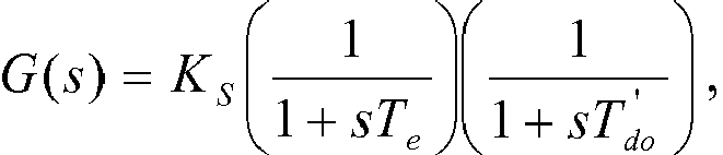
- The
gain K G 338 inFig. 5 is used for compensating variations in system configuration dependent gains such as power input voltage (VP ) 344 and saturation effects, i.e., loop gain, i.e., KG, multiplied by the system gain, i.e., KS, is equal to one (1). - First, the loop gain, i.e., KG, 338 is estimated based on a steady state condition that is preferably near the rated generator voltage. This is preferably accomplished with a robust controller having a soft start feature. The soft start feature is preferably designed to avoid a large voltage overshoot during voltage buildup.
- The
PID controller 340 is utilized to measure the voltageregulator output V R 350 andterminal voltage V T 354, as shown inFig. 5 . The voltageregulator output V R 350 andterminal voltage V T 354 are measured in a steady-state condition of the closed loop with thePID controller 340. The steady-state condition is determined when the generator voltage variation is less than a predetermined value, e.g., 0.005 p.u., for more than a predetermined time period, e.g., ten (10) seconds. The regulator output and generator voltage are utilized to obtain the loop gain, i.e., KG, 338. The steps for calculating the loop gain, i.e., KG, 338, would be as follows: (a) check residual voltage with a zero voltage regulator output; (b) find an open loop output that corresponds to the residual voltage; (c) find a regulator output corresponding to the nominal generator voltage using thePID controller 340; and (d) calculate loop gain, i.e., KG, 338, which is equal to thePID controller 340output voltage V R 350 divided by the sensedgenerator voltage V T 354, i.e., KG = VR /VT. - As shown in
Fig. 17 , a graphical user interface is generally indicated by numeral 1050. Thisgraphical user interface 1050 appears on theelectronic display 822, as shown inFig. 11 . Referring again toFig. 17 , there are five modes which include: identifyingloop gain K G 1002; identifyingtime constants 1004; stopidentification 1006; updatingPID gains 1008; and a softwareprogram exit function 1010. For identifyingloop gain 1002, there is an input for identification ofgain factor 1012. There is a click-oninput 1014 for pole zero cancellation as a design method for a PID controller and a click-oninput 1016 for pole placement as a design method for a PID controller. - For calculated PID, there are four outputs that include:
loop gain K G 1018;proportional gain K P 1020;integral gain K I 1022; andderivative gain K D 1024. Additional outputs include estimated time constants for theexciter T e 1026 and the generator T'do 1028. There are a series of inputs for creating graphical representations. These include a maximum value for the generator voltage on the y-axis 1034; a minimum value for the generator voltage on the y-axis 1036; a maximum value for the regulator voltage on the y-axis 1030; and a minimum value for the regulator voltage on the y-axis 1032. There is agraphical output icon 1038 for extending a width of the x-axis and agraphical output icon 1040 for reducing width of the x-axis. There is also an input for a width of the x-axis inseconds 1042. There is a graphical representation ofgenerator voltage 1044, e.g., value of 0.740 volts, and ofregulator output 1046, e.g., value of 0.106 volts. There is also a graphical representation of a time constant for theexciter T e 1052, e.g., value of 0.294, and a graphical representation of a time constant for the generator T'do 1054, e.g., value of 2.995. This software program monitors system and estimated parameters continuously. - Real-time monitoring feature was also implemented to easily evaluate system performance of the voltage step responses is shown in
Fig. 18 , which is generally indicated by numeral 1120. There are four push button feature icons that include: update PID gains fromcalculator 1062; startmonitor 1064; stopmonitor 1066; and anexit function 1068. There are five inputs for PID gains that include:loop gain K G 1070;proportional gain K P 1072;integral gain K I 1074;derivative gain K D 1076 and the derivative filter timeconstant T D 1078. There is also apush button icon 1088 to stop and start the automatic voltage regulator. - There is an
indicator 1080 to indicate an alarm condition as well as anindicator 1098 of whether the automatic voltage regulator is either stopped or started. Additionally, there is an input for ratedvoltage 1082, setpoint 1084, and percent (%) ofchange 1086. Moreover, apush button icon 1092 is used to increase the automatic voltage regulator to an upper predetermined value, e.g., 210, apush button icon 1094 to operate the automatic voltage regulator at a nominal value and apush button icon 1096 to decrease the automatic voltage regulator to a lower predetermined value, e.g., 190. - A drop-down
input 1100 for a first graph is used to graph parameters on the Y-axis, e.g., generator voltage. There is an input for both amaximum value 1102 and aminimum value 1104. There is a drop-downinput 1106 for a second graph to display parameters on the Y-axis, e.g., generator voltage. There is an input for both amaximum value 1108 and aminimum value 1110. There is a graphical output icon 1138 for extending a width of the x-axis and a graphical output icon 1140 for reducing width of the x-axis. There is also an input for a width of the x-axis in seconds 1142. There is a graphical representation ofregulator output voltage 1144, e.g., value of 0.040, and ofgenerator voltage 1146, e.g., value of 0.999. This is the automatic voltage regulator response utilizing default values, which indicates a large overshoot which is caused by improper gains. - The performance of proposed self-tuning algorithm was verified using with simplified first order exciter and generator simulation models. These models are also implemented in a commercial regulator for small size of generator set. Estimation results of the proposed method are shown in Table 1 shown in
Fig. 19 , which is generally indicated by numeral 1200. - The external power input case (fixed power input voltage, i.e., VP) is tested for comparison with a shunt application case. The results of two approaches are illustrated in the first table indicated by numeral 1202 for both a Recursive Least Square ("RLS") with linearization via feedback in comparison to the previously mentioned Particle Swarm Optimization ("PSO") technique. In this case, the RLS approach would appear to be more accurate.
- The second table is generally indicated by numeral 1204 for a shunt application for both a Recursive Least Square ("RLS") with linearization via feedback in comparison to the previously mentioned Particle Swarm Optimization ("PSO") technique. There is no significant error that is caused for the shunt application.
- The estimation error in the PSO approach is mainly caused by the incorrect starting time to apply the unit input to the exciter field, which is determined randomly at a time delay. A nonlimiting example of this time delay is about sixteen (16) milliseconds. In general, the random behavior is caused by inexact synchronization among the pulse width modulation ("PWM") signal update for the power amplifier, the rms calculation of 60 Hz voltage signal, and a real time interrupt time for control functions in the digital voltage regulator.
- The presence of ten percent (10%) relative error in generator voltage, the Particle Swarm Optimization ("PSO") approach arrives to a solution faster than the Recursive Least Square ("RLS"). For the Recursive Least Square ("RLS") approach, about thirty (30) seconds are required to converge to the time constants. On the other hand, it only takes several seconds for the Particle Swarm Optimization ("PSO") approach. This is shown on the third table indicated by numeral 1206. The typical identification results for the Particle Swarm Optimization ("PSO") approach is shown in
Fig. 20 , which is generally indicated by numeral 1210. The estimated values are indicated by numeral 1212 and the measured values are indicated by numeral 1214. The level of noise in the actual system step response is indicated by the measured values 1214. - As an illustrative, but nonlimiting example, performance of self-tuning algorithm is tested using the Diesel-Generating Set, which consists of a 75 kW, 208 Vac, 1800 RPM, 3 Phase synchronous generator. The excitation for this generator is provided by a permanent magnet generator ("PMG") excited 0.3 Amp, 7 Vdc, ac exciter at no load. Evaluation of system performance begins by performing voltage step responses to examine the behavior of the excitation system connected to the generator.
- An automatic voltage regulator ("AVR") uses default values is shown in
Fig. 21 , which is generally indicated by numeral 1220. There are four push button feature icons that include: update PID gains fromcalculator 1222; startmonitor 1224; stopmonitor 1226; and anexit function 1228. There are five inputs for PID gains that include:loop gain K G 1230;proportional gain K P 1232;integral gain K I 1234;derivative gain K D 1236 and the derivative filter timeconstant T D 1238. There is also apush button icon 1240 to stop and start the automatic voltage regulator. - There is an
indicator 1242 to indicate an alarm condition as well as anindicator 1244 of whether the automatic voltage regulator is either stopped or started. Additionally, there is an input for ratedvoltage 1246, setpoint 1248, and percent (%) ofchange 1250. Moreover, apush button icon 1252 is used to increase the automatic voltage regulator to an upper predetermined value, e.g., 210, apush button icon 1254 to operate the automatic voltage regulator at a nominal value and apush button icon 1256 to decrease the automatic voltage regulator to a lower predetermined value, e.g., 190. - A drop-down
input 1258 for a first graph is used to graph parameters on the Y-axis, e.g., regulator output. There is an input for both amaximum value 1260 and aminimum value 1262. There is a drop-downinput 1264 for a second graph to display parameters on the Y-axis, e.g., generator voltage. There is an input for both amaximum value 1266 and aminimum value 1268. There is agraphical output icon 1270 for extending a width of the x-axis and agraphical output icon 1272 for reducing width of the x-axis. There is also an input for a width of the x-axis inseconds 1274. There is a graphical representation ofregulator output 1276, e.g., value of 0.031, and ofgenerator voltage 1278, e.g., value of 0.999. This is the automatic voltage regulator response utilizing default values, which indicates a large overshoot which is caused by improper gains. - Since exciter and generator time constants are not available, factory PID gains (KP = 200 shown by
input 1232, KI =600 shown byinput 1234, KD = 30 shown byinput 1236, and TD = 0.0 shown by input 1238) were selected, which was obtained for other generator by trial-and-error method. Since the factory gain for KG = 50 causes a large overshoot, it was reduced to KG = 1.0, shown byinput 1230, to get areasonable response - The self-tuning PID gains are shown in
Fig. 22 , which is generally indicated by numeral 1320. There are four push button feature icons that include: update PID gains fromcalculator 1322; startmonitor 1324; stopmonitor 1326; and anexit function 1328. There are five inputs for PID gains that include:loop gain K G 1330;proportional gain K P 1332;integral gain K I 1334;derivative gain K D 1336 and the derivative filter timeconstant T D 1338. There is also apush button icon 1340 to stop and start the automatic voltage regulator. - There is an
indicator 1342 to indicate an alarm condition as well as anindicator 1344 of whether the automatic voltage regulator is either stopped or started. Additionally, there is an input for ratedvoltage 1346, setpoint 1348, and percent (%) ofchange 1350. Moreover, apush button icon 1352 is used to increase the automatic voltage regulator to an upper predetermined value, e.g., 210, apush button icon 1354 to operate the automatic voltage regulator at a nominal value and apush button icon 1356 to decrease the automatic voltage regulator to a lower predetermined value, e.g., 190. - A drop-down
input 1358 for a first graph is used to graph parameters on the Y-axis, e.g., regulator output. There is an input for both amaximum value 1360 and aminimum value 1362. There is a drop-downinput 1364 for a second graph to display parameters on the Y-axis, e.g., generator voltage. There is an input for both amaximum value 1366 and aminimum value 1368. There is agraphical output icon 1370 for extending a width of the x-axis and agraphical output icon 1372 for reducing a width of the x-axis. There is also an input for a width of the x-axis inseconds 1374. There is a graphical representation ofregulator output 1376, e.g., value of 0.040, and ofgenerator voltage 1378, e.g., value of 0.999. This is the response utilizing self-tuning PID gains. - This software program is designed for self-tuning features so that when the self-tuning mode is activated, PID gains are determined based on rising time and estimated parameters (system gain and exciter/generator time constants) using pole-zero cancellation method (KP = 57.81 shown by
input 1332, KI = 110.15 shown byinput 1334, and KD = 6.53 shown by input 1336). The time constant for derivative term was selected TD = 0.03, shown byinput 1338, to reduce the noise effect. Much less commission time was required with the self-tuning feature. - The voltage step response of the first method using the automatic voltage regulator ("AVR") with default values is shown by
numerals Fig. 21 , is compared to self-tuning PID gains shown bynumerals Fig. 22 . The automatic voltage regulator ("AVR") with default values is shown bynumerals Fig. 21 indicates a large overshoot with improper gains. The self-tuning PID gains, shown bynumerals Fig. 22 , provide a response with much less overshoot. The large overshoot in step up response is caused by asymmetric high forcing limit. This is a typical response for a rotary excitation control system which has no negative field forcing. For this case, the selection of proper controller gains is more important. - The self-tuning PID gains for a medium level of generator set with a gas turbine and generator rated at 13.8 kV and 15 MVA, respectively, is shown in
Fig. 23 , which is generally indicated by numeral 1420. There are four push button feature icons that include: update PID gains fromcalculator 1422; startmonitor 1424; stopmonitor 1426; and anexit function 1428. There are five inputs for PID gains that include:loop gain K G 1430;proportional gain K P 1432;integral gain K I 1434;derivative gain K D 1436 and the derivative filter timeconstant T D 1438. There is also apush button icon 1440 to stop and start the automatic voltage regulator. - There is an
indicator 1442 to indicate an alarm condition as well as anindicator 1444 of whether the automatic voltage regulator is either stopped or started. Additionally, there is an input for ratedvoltage 1446, setpoint 1448, and percent (%) ofchange 1450. Moreover, apush button icon 1452 is used to increase the automatic voltage regulator to an upper predetermined value, e.g., 14,161.581 Volts, apush button icon 1454 to operate the automatic voltage regulator at a nominal value and apush button icon 1456 to decrease the automatic voltage regulator to a lower predetermined value, e.g., 12,812.859 Volts. - A drop-down
input 1458 for a first graph is used to graph parameters on the Y-axis, e.g., generator voltage. There is an input for both amaximum value 1460 and aminimum value 1462. There is a drop-downinput 1464 for a second graph to display parameters on the Y-axis, e.g., regulator output. There is an input for both amaximum value 1466 and aminimum value 1468. There is agraphical output icon 1470 for extending a width of the x-axis and agraphical output icon 1472 for reducing a width of the x-axis. There is also an input for a width of the x-axis inseconds 1474. There is a graphical representation ofgenerator voltage 1476, e.g., value of .977, and ofregulator output 1478, e.g., value of 0.051. This is the response utilizing self-tuning PID gains. - This software program is designed for self-tuning features so that when the self-tuning mode is activated, PID gains are determined based on rising time and estimated parameters (system gain and exciter/generator time constants) using pole-zero cancellation method (KP = 222 shown by
input 1432, KI = 109.86 shown byinput 1434, and KD = 73.89 shown by input 1436). The time constant for derivative term was selected TD = 0.08, shown byinput 1438, to reduce the noise effect. As before, there is much less commission time was required with the self-tuning feature. - The Particle Swarm Optimization ("PSO") technique was found to be faster than a Recursive Least Square ("RLS") technique at estimating exciter and generator time constants. The computational speed is particularly important for small automatic voltage regulators (AVRs), where processing power comes with a high cost.
- Although less estimation error can be obtained with Recursive Least Square ("RLS") approach than Particle Swarm Optimization ("PSO"), the Particle Swarm Optimization ("PSO") approach arrives to a solution faster than Recursive Least Square ("RLS") since all calculations can be achieved by the software program. For the Recursive Least Square ("RLS") approach, about 30 seconds are required to converge to the time constants with 10% error of rms voltage calculation. On the other hand, it takes several seconds for the Particle Swarm Optimization ("PSO") approach using standard personal computer, e.g., 2
GHz Intel Core 2 CPU. - The Particle Swarm Optimization ("PSO") technique was found to have very good accuracy and the results achieved by Particle Swarm Optimization ("PSO") technique were similar to those found using Recursive Least Square ("RLS") technique. Another advantage of the Particle Swarm Optimization ("PSO") approach is that continuous excitation is not required. Only one step response is performed and PID gains are calculated by computer program. Therefore, Particle Swarm Optimization ("PSO") approach is very desirable when working with a small automatic voltage regulator that does not have computational capabilities. Exemplary embodiments of the present invention therefore allow fast commissioning of generator sets with good performance results.
- Thus, there has been shown and described several embodiments of a novel invention. As is evident from the foregoing description, certain aspects of the present invention are not limited by the particular details of the examples illustrated herein, and it is therefore contemplated that other modifications and applications, or equivalents thereof, will occur to those skilled in the art. The terms "have," "having," "includes" and "including" and similar terms as used in the foregoing specification are used in the sense of "optional" or "may include" and not as "required." Many changes, modifications, variations and other uses and applications of the present construction will, however, become apparent to those skilled in the art after considering the specification and the accompanying drawings. All such changes, modifications, variations and other uses and applications which do not depart from the disclosure are deemed to be covered by the invention which is limited only by the claims that follow.
Claims (22)
- A system for self-tuning a PID controller utilized with an exciter having an exciter field voltage electrically connected to a voltage regulator having an exciter field output voltage, and a generator that is electrically energized by the exciter and having a generator output voltage, the system comprising:means for providing a voltage regulator including a power source that produces the exciter field output voltage and a processor configured to act as a PID controller;the processor further configured to calculate a system gain from the generator output voltage, a residual voltage, and the exciter field output voltage;the processor further configured to calculate an estimated exciter time constant and an estimated generator time constant using particle swarm optimization by determining a generator output voltage step response by increasing the output voltage of the power source by a predetermined percentage over a predetermined time period, initializing each particle position of exciter time constant and generator time constant, calculating generator voltage, performing a fitness evaluation and then obtaining and updating best values for the estimated exciter time constant and the estimated generator time constant;the processor further configured to utilize the system gain, estimated exciter time constant and the estimated generator time constant to calculate optimized PID gains; andwherein the PID controller is configured for utilizing the optimized PID gains to control the exciter field output voltage.
- The system for self-tuning a PID controller from a generator output voltage and an exciter field output voltage according to Claim 1, wherein the voltage regulator is configured to receive as input a comparison of a digital value of rms generator voltage against a reference voltage.
- The system for self-tuning a PID controller for self-tuning a PID controller from a generator output voltage and an exciter field output voltage according to Claim 2, wherein the voltage regulator further includes an analog-to-digital converter, and is configured to convert an analog generator output voltage to the digital value of rms generator output voltage.
- The system for self-tuning a PID controller from a generator output voltage and an exciter field output voltage according to Claim 1, wherein the voltage regulator further includes a switch that is electrically connected to the power source, and the processor further configured to regulate the exciter field output voltage using the switch; and
wherein the electrical connection between the exciter and the voltage regulator provides the exciter field output voltage as the exciter field voltage. - The system for self-tuning a PID controller from a generator output voltage and an exciter field output voltage according to Claim 1, wherein the PID controller is configured to use pole zero cancellation.
- The system for self-tuning a PID controller from a generator output voltage and an exciter field output voltage according to Claim 1, wherein the PID controller is configured to use pole placement.
- The system for self-tuning a PID controller from a generator output voltage and an exciter field output voltage according to-Claim 1, wherein the PID controller is configured to utilize a predetermined number of iterations to generate the calculated generator output voltage, the fitness evaluation and the best values.
- The system for self-tuning a PID controller from a generator output voltage and an exciter field output voltage according to Claim 1, wherein the PID controller is configured to perform the fitness evaluation by utilizing a summation of a plurality of values that represent the difference between a plurality of measured generator output voltages and corresponding plurality of calculated generator output voltages.
- The system for self-tuning a PID controller from a generator output voltage and an exciter field output voltage according to Claim 1, wherein the PID controller is configured to set the initialized particle positions of exciter time constant and generator time constant within boundaries and a velocity to zero.
- The system for self-tuning a PID controller from a generator output voltage and an exciter field output voltage according to Claim 1, wherein the PID controller is configured to calculate generator output voltage by utilizing a predetermined time constant and initial conditions, calculating closed loop voltage error, calculating voltage regulator exciter field output voltage and calculating a new generator output voltage and then repeating for a predetermined number of iterations calculating the closed loop voltage error, calculating the voltage regulator exciter field output voltage and calculating the new generator output voltage.
- A method for self-tuning a PID controller utilized with an exciter having an exciter field voltage and electrically connected to a voltage regulator having an exciter field output voltage, and a generator that is electrically energized by the exciter and having a generator output voltage, the method comprising the steps of:a. providing, by the voltage regulator, a power source that produces the exciter field output voltage and a processor configured to act as the PID controller that utilizes PID gains to control the exciter field output voltage of the power source;b. calculating, by the processor, a system gain from the generator output voltage, a residual voltage, and the exciter field output voltage, and an estimated exciter time constant and an estimated generator time constant using particle swarm optimization by determining a generator output voltage step response by increasing the voltage output of the power source by a predetermined percentage over a predetermined time period, initializing each particle position of exciter time constant and generator time constant, calculating the generator output voltage, performing a fitness evaluation and then obtaining and updating best values for the estimated exciter time constant and the estimated generator time constant;c. calculating, by the processor, optimized PID gains from the system gain, estimated exciter time constant and the estimated generator time; andd. utilizing, by the PID controller, the optimized PID gains to control the exciter field output voltage.
- The method for self-tuning a PID controller from a generator output voltage and an exciter field output voltage of Claim 11, wherein the method further comprises:converting an analog a.c. generator output voltage to a digital value of rms generator output voltage with an analog-to-digital converter; andcomparing the digital value of rms generator output voltage against a reference voltage as input into the PID controller associated with the processor.
- The method for self-tuning a PID controller from a generator output voltage and an exciter field output voltage according to Claim 12, wherein the step of performing a fitness evaluation further includes creating a summation of a plurality of values that represent the difference between a plurality of measured generator output voltages and corresponding plurality of calculated generator output voltages with the PID controller.
- The method for self-tuning a PID controller from a generator output voltage and an exciter field output voltage according to Claim 12, wherein the step of calculating the generator output voltage further includes the steps of:(a) utilizing a predetermined time constant and initial conditions;(b) calculating closed loop voltage error;(c) calculating the voltage regulator exciter field output voltage;(d) calculating a new generator voltage; and then repeating steps (b) through (d) over a predetermined number of iterations.
- The method for self-tuning a PID controller from a generator output voltage and an exciter field output voltage according to Claim 11, wherein the voltage regulator receiving as an input a comparison of a digital value of rms generator output voltage against a reference voltage.
- The method for self-tuning a PID controller from a generator output voltage and an exciter field output voltage according to Claim 11, wherein the voltage regulator further comprises a switch that is electrically connected to the power source, and the step of the processor regulating the exciter field output voltage using the switch; and
wherein the electrical connection between the exciter and the voltage regulator provides the exciter field output voltage as the exciter field voltage. - The method for self-tuning a PID controller from a generator output voltage and an exciter field output voltage according to Claim 11, further comprising the step of implementing the PID controller using pole zero cancellation.
- The method for self-tuning a PID controller from a generator output voltage and an exciter field output voltage according to Claim 11, further comprising the step of implementing the PID controller using pole placement.
- The method for self-tuning a PID controller from a generator output voltage and an exciter field output voltage according to Claim 11, further comprising the step of the PID controller utilizing a predetermined number of iterations to generate the calculated generator voltage, the fitness evaluation and the best values.
- The method for self-tuning a PID controller from a generator output voltage and an exciter field output voltage according to Claim 11, further comprising the step of the PID controller setting the initialized particle positions of exciter time constant and generator time constant within boundaries and a velocity to zero.
- The method for self-tuning a PID controller from a generator output voltage and an exciter field output voltage according to Claim 11, wherein the processor comprises:a first processor configured to provide the PID controller;a second processor configured to determine the system gain, the exciter time constant, the generator time constant and the optimized PID gains;further comprising the steps of:f. electrically connecting the first processor to the second processor through a communications link;g. transmitting, by the second processor, the optimized PID gains to the first processor through the communications link;h. receiving, by the first processor, the optimized PID gains from the second processor through the communications link; andi. providing, by the first processor, the optimized PID gains to the PID controller.
- The system for self-tuning a PID controller from a generator output voltage and an exciter field output voltage according to Claim 1, wherein the processor comprises:a first processor configured to provide the PID controller;a second processor configured to determine the system gain, the exciter time constant, the generator time constant and the optimized PID gains;the first processor electrically connected to the second processor through a communications link;the second processor further configured to transmit the optimized PID gains to the first processor through the communications link; andthe first processor further configured to receive the optimized PID gains from the second processor through the communications link and to provide the optimized PID gains to the PID controller.
Priority Applications (1)
| Application Number | Priority Date | Filing Date | Title |
|---|---|---|---|
| PL09706546T PL2245732T3 (en) | 2008-01-31 | 2009-02-02 | Digital excitation control system for an electrical generator and an associated method of use |
Applications Claiming Priority (3)
| Application Number | Priority Date | Filing Date | Title |
|---|---|---|---|
| US12/023,145 US20090195224A1 (en) | 2008-01-31 | 2008-01-31 | Digital Excitation Control System Utilizing Self-Tuning PID Gains and an Associated Method of Use |
| US12/183,781 US8275488B2 (en) | 2008-01-31 | 2008-07-31 | Digital excitation control system utilizing swarm intelligence and an associated method of use |
| PCT/US2009/032834 WO2009097605A1 (en) | 2008-01-31 | 2009-02-02 | Digital excitation control system for an electrical generator and an associated method of use |
Publications (3)
| Publication Number | Publication Date |
|---|---|
| EP2245732A1 EP2245732A1 (en) | 2010-11-03 |
| EP2245732A4 EP2245732A4 (en) | 2015-12-30 |
| EP2245732B1 true EP2245732B1 (en) | 2017-12-20 |
Family
ID=40913302
Family Applications (1)
| Application Number | Title | Priority Date | Filing Date |
|---|---|---|---|
| EP09706546.0A Active EP2245732B1 (en) | 2008-01-31 | 2009-02-02 | Digital excitation control system for an electrical generator and an associated method of use |
Country Status (7)
| Country | Link |
|---|---|
| US (1) | US8275488B2 (en) |
| EP (1) | EP2245732B1 (en) |
| BR (1) | BRPI0906753B8 (en) |
| ES (1) | ES2662668T3 (en) |
| HU (1) | HUE036616T2 (en) |
| PL (1) | PL2245732T3 (en) |
| WO (1) | WO2009097605A1 (en) |
Cited By (1)
| Publication number | Priority date | Publication date | Assignee | Title |
|---|---|---|---|---|
| US11689135B2 (en) | 2019-06-06 | 2023-06-27 | Abb Schweiz Ag | Automatically determining control parameters for a voltage regulator of a synchronous machine |
Families Citing this family (46)
| Publication number | Priority date | Publication date | Assignee | Title |
|---|---|---|---|---|
| US8031940B2 (en) * | 2006-06-29 | 2011-10-04 | Google Inc. | Recognizing text in images using ranging data |
| US8866626B2 (en) | 2008-01-31 | 2014-10-21 | Basler Electric Company | System and method for detecting generator incipient failures |
| US8276106B2 (en) * | 2009-03-05 | 2012-09-25 | International Business Machines Corporation | Swarm intelligence for electrical design space modeling and optimization |
| US8255066B2 (en) * | 2009-05-18 | 2012-08-28 | Imb Controls Inc. | Method and apparatus for tuning a PID controller |
| JP5408535B2 (en) * | 2009-07-10 | 2014-02-05 | 日立工機株式会社 | Electric tool |
| KR101033816B1 (en) * | 2009-09-03 | 2011-05-13 | (주)유스텍 | Proportional Calculus Control Device for Motion Control of Motor and Its Control Method |
| US8550038B2 (en) * | 2009-10-05 | 2013-10-08 | Cummins Power Generation Ip, Inc. | Generator set cooling control system |
| US8572004B2 (en) * | 2009-12-29 | 2013-10-29 | International Business Machines Corporation | Space solution search |
| US10289753B2 (en) | 2010-07-07 | 2019-05-14 | Simon Fraser University | Methods and systems for guidance of human locomotion |
| WO2012040178A1 (en) * | 2010-09-24 | 2012-03-29 | Waters Technologies Corporation | Techniques for automated software testing |
| JP5683000B2 (en) * | 2010-09-30 | 2015-03-11 | インターナショナル・ビジネス・マシーンズ・コーポレーションInternational Business Machines Corporation | PID controller configuration method, program and system |
| CN101965043A (en) * | 2010-10-27 | 2011-02-02 | 北京邮电大学 | Adaptive power control-based inter-cell interference coordination method |
| CN101977428A (en) * | 2010-10-27 | 2011-02-16 | 北京邮电大学 | Adaptive power control-based energy saving method |
| US9293914B2 (en) | 2011-11-04 | 2016-03-22 | Kohler Co | Power management system that includes a generator controller |
| US9991709B2 (en) | 2011-11-04 | 2018-06-05 | Kohler Co. | Adding and shedding loads using load levels to determine timing |
| US8942854B2 (en) | 2011-11-28 | 2015-01-27 | Kohler Co. | System and method for identifying electrical devices in a power management system |
| US9281716B2 (en) | 2011-12-20 | 2016-03-08 | Kohler Co. | Generator controller configured for preventing automatic transfer switch from supplying power to the selected load |
| US20130158726A1 (en) | 2011-12-20 | 2013-06-20 | Kohler Co. | System and method for using a network to control multiple power management systems |
| US8836163B2 (en) * | 2012-02-14 | 2014-09-16 | University Of Tennessee Research Foundation | Adaptive controller for STATCOM to enhance voltage stability |
| US9075407B2 (en) | 2012-12-13 | 2015-07-07 | King Fahd University Of Petroleum And Minerals | Reduced complexity auto-tuning process controller system and method |
| US8933572B1 (en) | 2013-09-04 | 2015-01-13 | King Fahd University Of Petroleum And Minerals | Adaptive superconductive magnetic energy storage (SMES) control method and system |
| US9252695B2 (en) * | 2014-03-12 | 2016-02-02 | General Electric Company | Brushless permanent magnet generator plus auxiliary voltage source constant potential exciter |
| EP2945278B1 (en) * | 2014-05-12 | 2021-03-03 | General Electric Technology GmbH | Static exciter system for generators |
| US9574511B2 (en) * | 2014-07-24 | 2017-02-21 | Basler Electric Company | System and method for a load anticipation feature and its tuning method for a generating set |
| US9835160B2 (en) | 2014-12-08 | 2017-12-05 | General Electric Company | Systems and methods for energy optimization for converterless motor-driven pumps |
| US10054965B2 (en) * | 2015-08-06 | 2018-08-21 | Honeywell International Inc. | Analog/digital input architecture having programmable analog output mode |
| US10641507B2 (en) * | 2015-09-16 | 2020-05-05 | Siemens Industry, Inc. | Tuning building control systems |
| CN108845490A (en) * | 2018-06-23 | 2018-11-20 | 广东希望高科数字技术有限公司 | A kind of identical tension of Tension Adjustable, which synchronizes, unreels control system |
| CN109062040B (en) * | 2018-07-27 | 2021-12-10 | 湖北工业大学 | PID (proportion integration differentiation) predicting method based on system nesting optimization |
| KR102225315B1 (en) * | 2019-06-03 | 2021-03-10 | 재단법인대구경북과학기술원 | Apparatus and method for controlling system |
| US11146193B2 (en) | 2019-10-14 | 2021-10-12 | Schweitzer Engineering Laboratories, Inc. | Genset engine paralleling controls, devices, systems, and methods |
| US11012016B2 (en) * | 2019-10-14 | 2021-05-18 | Schweitzer Engineering Laboratories, Inc. | Energy packet control of generator prime mover |
| TWI708470B (en) * | 2020-02-21 | 2020-10-21 | 龍華科技大學 | A power converter |
| BR112022023417A2 (en) * | 2020-05-28 | 2023-01-24 | Basler Electric Co | SYSTEM AND METHOD FOR AUTOMATICALLY ADJUSTING/CONFIGURING A POWER SYSTEM STABILIZER (PSS) IN A DIGITAL EXCITATION CONTROL SYSTEM |
| CN112332731B (en) * | 2020-10-27 | 2024-09-03 | 连云港杰瑞电子有限公司 | A self-tuning motion control system and method |
| CN112733424B (en) * | 2020-12-12 | 2023-08-01 | 国网新源控股有限公司回龙分公司 | Modeling simulation method and system for pumped storage power station generator |
| CN113467225A (en) * | 2021-06-24 | 2021-10-01 | 王珠 | Intelligent PID controller online optimization method and system |
| CN113759697B (en) * | 2021-08-21 | 2023-03-10 | 天津工业大学 | Optimizing Method for PSO Intelligent Setting of PID Controller Parameters of Belt Conveyor |
| CN114123937B (en) * | 2021-10-22 | 2024-04-09 | 衢州元立金属制品有限公司 | Smooth conversion method for realizing manual and automatic PID adjustment |
| CN114244192B (en) * | 2021-11-13 | 2024-04-12 | 黄河交通学院 | Multifunctional synchronous motor excitation device based on PLC control |
| US11777426B2 (en) | 2022-02-21 | 2023-10-03 | Schweitzer Engineering Laboratories, Inc. | Energy packet control of generator prime mover and control processing |
| CN116844654B (en) * | 2023-04-12 | 2024-07-05 | 湖北三峡实验室 | LS-SVM-based method for optimizing and predicting phosphogypsum soluble phosphorus and fluorine leaching removal conditions |
| CN118367680B (en) * | 2024-04-29 | 2024-09-27 | 广西贝多力电子科技有限公司 | An intelligent drive control system and method for monitoring power equipment |
| CN118944104B (en) * | 2024-10-14 | 2025-03-25 | 河南才鸿电力安装有限公司 | Cold Region Power System and Voltage Automatic Control Method |
| CN119743065A (en) * | 2024-12-16 | 2025-04-01 | 迈为技术(珠海)有限公司 | Motor control method, apparatus, computer device, readable storage medium, and program product |
| CN120150572B (en) * | 2025-03-14 | 2025-09-16 | 浙江大学 | A method for switching working conditions of a starting-integrated permanent magnet motor in an aviation power system |
Family Cites Families (14)
| Publication number | Priority date | Publication date | Assignee | Title |
|---|---|---|---|---|
| JP2563894B2 (en) | 1982-09-25 | 1996-12-18 | 株式会社東芝 | Multi-input / output sample value PID controller |
| US5124626A (en) | 1990-12-20 | 1992-06-23 | Mts Systems Corporation | Sinusoidal signal amplitude and phase control for an adaptive feedback control system |
| US5294879A (en) | 1991-11-01 | 1994-03-15 | Basler Electric Company | Microprocessor-controlled regulator |
| US5691896A (en) | 1995-08-15 | 1997-11-25 | Rosemount, Inc. | Field based process control system with auto-tuning |
| US6549858B1 (en) | 1998-02-03 | 2003-04-15 | Sheet Dynamics, Ltd. | Structural control and monitoring using adaptive spatio-temporal filtering |
| US6760716B1 (en) | 2000-06-08 | 2004-07-06 | Fisher-Rosemount Systems, Inc. | Adaptive predictive model in a process control system |
| US7113834B2 (en) | 2000-06-20 | 2006-09-26 | Fisher-Rosemount Systems, Inc. | State based adaptive feedback feedforward PID controller |
| US6577908B1 (en) | 2000-06-20 | 2003-06-10 | Fisher Rosemount Systems, Inc | Adaptive feedback/feedforward PID controller |
| US7024253B2 (en) | 2000-08-21 | 2006-04-04 | Honeywell International Inc. | Auto-tuning controller using loop-shaping |
| US6697767B2 (en) | 2000-10-18 | 2004-02-24 | The National University Of Singapore | Robust process identification and auto-tuning control |
| US6700356B1 (en) | 2000-10-24 | 2004-03-02 | Kohler Co. | Method and apparatus for regulating the excitation of an alternator of a genset |
| US7317953B2 (en) | 2003-12-03 | 2008-01-08 | Fisher-Rosemount Systems, Inc. | Adaptive multivariable process controller using model switching and attribute interpolation |
| US8131656B2 (en) | 2006-01-31 | 2012-03-06 | The Board Of Trustees Of The University Of Illinois | Adaptive optimization methods |
| US8190299B2 (en) * | 2006-07-19 | 2012-05-29 | Rovnyak Steven M | Integrated and optimized distributed generation and interconnect system controller |
-
2008
- 2008-07-31 US US12/183,781 patent/US8275488B2/en active Active
-
2009
- 2009-02-02 ES ES09706546.0T patent/ES2662668T3/en active Active
- 2009-02-02 WO PCT/US2009/032834 patent/WO2009097605A1/en not_active Ceased
- 2009-02-02 EP EP09706546.0A patent/EP2245732B1/en active Active
- 2009-02-02 PL PL09706546T patent/PL2245732T3/en unknown
- 2009-02-02 BR BRPI0906753A patent/BRPI0906753B8/en active IP Right Grant
- 2009-02-02 HU HUE09706546A patent/HUE036616T2/en unknown
Non-Patent Citations (1)
| Title |
|---|
| None * |
Cited By (1)
| Publication number | Priority date | Publication date | Assignee | Title |
|---|---|---|---|---|
| US11689135B2 (en) | 2019-06-06 | 2023-06-27 | Abb Schweiz Ag | Automatically determining control parameters for a voltage regulator of a synchronous machine |
Also Published As
| Publication number | Publication date |
|---|---|
| EP2245732A4 (en) | 2015-12-30 |
| US20090198386A1 (en) | 2009-08-06 |
| US8275488B2 (en) | 2012-09-25 |
| HUE036616T2 (en) | 2018-07-30 |
| ES2662668T3 (en) | 2018-04-09 |
| BRPI0906753B8 (en) | 2021-07-06 |
| WO2009097605A1 (en) | 2009-08-06 |
| BRPI0906753B1 (en) | 2019-09-03 |
| EP2245732A1 (en) | 2010-11-03 |
| BRPI0906753A2 (en) | 2015-07-07 |
| PL2245732T3 (en) | 2018-06-29 |
Similar Documents
| Publication | Publication Date | Title |
|---|---|---|
| US8275488B2 (en) | Digital excitation control system utilizing swarm intelligence and an associated method of use | |
| US20090195224A1 (en) | Digital Excitation Control System Utilizing Self-Tuning PID Gains and an Associated Method of Use | |
| US9574511B2 (en) | System and method for a load anticipation feature and its tuning method for a generating set | |
| Kim et al. | Self-tuning of the PID controller for a digital excitation control system | |
| US10950378B2 (en) | Methods and systems for controlling electromagnetic field generators | |
| EP3161563B1 (en) | Adaptive pid control system for industrial turbines | |
| Orlowska-Kowalska et al. | Optimization of fuzzy-logic speed controller for DC drive system with elastic joints | |
| EP3591836A1 (en) | Processing device | |
| CN108351621B (en) | Adaptive multiple input multiple output PID control system for industrial turbines | |
| CN110268340A (en) | Processing device, control parameter determination method, and control parameter determination program | |
| US11689135B2 (en) | Automatically determining control parameters for a voltage regulator of a synchronous machine | |
| RU2552891C1 (en) | Control method | |
| Bora et al. | A novel objective function design and detailed analysis for the AVR-LFC system | |
| US12068607B2 (en) | System and method for automated tuning/configuring of a power system stabilizer (PSS) in a digital excitation control system | |
| Pantonial et al. | Real time thermal estimation of a Brushed DC Motor by a steady-state Kalman filter algorithm in multi-rate sampling scheme | |
| Syed et al. | Performance improvement of doubly fed induction generator using grey wolf optimization | |
| CN110611467B (en) | Pump analog control system | |
| CN110609490B (en) | Converter pump simulation control system | |
| Telang et al. | Optimization-Based State Feedback and Observer Design for Speed Control and Stability Enhancement in DC Motors | |
| Chouiter et al. | On the robust control of an induction machine: A complete design and realization | |
| Ho et al. | On-Line Efficiency-Optimization Control of Induction Motor Drives Using Particle Swarm Optimization Algorithm | |
| Huang et al. | Research on Voice Coil Motor Control Considering Interference | |
| Kumar et al. | Adaptive Control of Synchronous Reluctance Motor via Estimation of Machine Inertia and Friction Coefficient | |
| Qadir | Electro-Mechanical Modeling of Separately Excited DC Motor & Performance Improvement using different Industrial Controllers with Active Circuit Realization | |
| CN121364392A (en) | Rotary motor multi-type load simulation device and method based on sliding mode control |
Legal Events
| Date | Code | Title | Description |
|---|---|---|---|
| PUAI | Public reference made under article 153(3) epc to a published international application that has entered the european phase |
Free format text: ORIGINAL CODE: 0009012 |
|
| 17P | Request for examination filed |
Effective date: 20100830 |
|
| AK | Designated contracting states |
Kind code of ref document: A1 Designated state(s): AT BE BG CH CY CZ DE DK EE ES FI FR GB GR HR HU IE IS IT LI LT LU LV MC MK MT NL NO PL PT RO SE SI SK TR |
|
| AX | Request for extension of the european patent |
Extension state: AL BA RS |
|
| DAX | Request for extension of the european patent (deleted) | ||
| RA4 | Supplementary search report drawn up and despatched (corrected) |
Effective date: 20151202 |
|
| RIC1 | Information provided on ipc code assigned before grant |
Ipc: G05B 13/04 20060101AFI20151126BHEP Ipc: G05B 11/42 20060101ALI20151126BHEP Ipc: H02P 9/10 20060101ALI20151126BHEP |
|
| REG | Reference to a national code |
Ref country code: DE Ref legal event code: R079 Ref document number: 602009049957 Country of ref document: DE Free format text: PREVIOUS MAIN CLASS: H02P0009100000 Ipc: G05B0013040000 |
|
| GRAP | Despatch of communication of intention to grant a patent |
Free format text: ORIGINAL CODE: EPIDOSNIGR1 |
|
| RIC1 | Information provided on ipc code assigned before grant |
Ipc: H02P 9/10 20060101ALI20160920BHEP Ipc: G05B 13/04 20060101AFI20160920BHEP Ipc: G05B 11/42 20060101ALI20160920BHEP |
|
| INTG | Intention to grant announced |
Effective date: 20161007 |
|
| GRAJ | Information related to disapproval of communication of intention to grant by the applicant or resumption of examination proceedings by the epo deleted |
Free format text: ORIGINAL CODE: EPIDOSDIGR1 |
|
| GRAP | Despatch of communication of intention to grant a patent |
Free format text: ORIGINAL CODE: EPIDOSNIGR1 |
|
| INTC | Intention to grant announced (deleted) | ||
| INTG | Intention to grant announced |
Effective date: 20161223 |
|
| GRAJ | Information related to disapproval of communication of intention to grant by the applicant or resumption of examination proceedings by the epo deleted |
Free format text: ORIGINAL CODE: EPIDOSDIGR1 |
|
| INTC | Intention to grant announced (deleted) | ||
| GRAP | Despatch of communication of intention to grant a patent |
Free format text: ORIGINAL CODE: EPIDOSNIGR1 |
|
| INTG | Intention to grant announced |
Effective date: 20170710 |
|
| GRAS | Grant fee paid |
Free format text: ORIGINAL CODE: EPIDOSNIGR3 |
|
| GRAA | (expected) grant |
Free format text: ORIGINAL CODE: 0009210 |
|
| AK | Designated contracting states |
Kind code of ref document: B1 Designated state(s): AT BE BG CH CY CZ DE DK EE ES FI FR GB GR HR HU IE IS IT LI LT LU LV MC MK MT NL NO PL PT RO SE SI SK TR |
|
| REG | Reference to a national code |
Ref country code: GB Ref legal event code: FG4D |
|
| REG | Reference to a national code |
Ref country code: CH Ref legal event code: EP |
|
| REG | Reference to a national code |
Ref country code: IE Ref legal event code: FG4D |
|
| REG | Reference to a national code |
Ref country code: AT Ref legal event code: REF Ref document number: 956907 Country of ref document: AT Kind code of ref document: T Effective date: 20180115 |
|
| REG | Reference to a national code |
Ref country code: DE Ref legal event code: R096 Ref document number: 602009049957 Country of ref document: DE |
|
| REG | Reference to a national code |
Ref country code: FR Ref legal event code: PLFP Year of fee payment: 10 |
|
| REG | Reference to a national code |
Ref country code: CH Ref legal event code: NV Representative=s name: RENTSCH PARTNER AG, CH |
|
| REG | Reference to a national code |
Ref country code: RO Ref legal event code: EPE |
|
| REG | Reference to a national code |
Ref country code: ES Ref legal event code: FG2A Ref document number: 2662668 Country of ref document: ES Kind code of ref document: T3 Effective date: 20180409 |
|
| REG | Reference to a national code |
Ref country code: NL Ref legal event code: MP Effective date: 20171220 |
|
| PG25 | Lapsed in a contracting state [announced via postgrant information from national office to epo] |
Ref country code: NO Free format text: LAPSE BECAUSE OF FAILURE TO SUBMIT A TRANSLATION OF THE DESCRIPTION OR TO PAY THE FEE WITHIN THE PRESCRIBED TIME-LIMIT Effective date: 20180320 Ref country code: LT Free format text: LAPSE BECAUSE OF FAILURE TO SUBMIT A TRANSLATION OF THE DESCRIPTION OR TO PAY THE FEE WITHIN THE PRESCRIBED TIME-LIMIT Effective date: 20171220 Ref country code: SE Free format text: LAPSE BECAUSE OF FAILURE TO SUBMIT A TRANSLATION OF THE DESCRIPTION OR TO PAY THE FEE WITHIN THE PRESCRIBED TIME-LIMIT Effective date: 20171220 |
|
| REG | Reference to a national code |
Ref country code: LT Ref legal event code: MG4D |
|
| PG25 | Lapsed in a contracting state [announced via postgrant information from national office to epo] |
Ref country code: BG Free format text: LAPSE BECAUSE OF FAILURE TO SUBMIT A TRANSLATION OF THE DESCRIPTION OR TO PAY THE FEE WITHIN THE PRESCRIBED TIME-LIMIT Effective date: 20180320 Ref country code: GR Free format text: LAPSE BECAUSE OF FAILURE TO SUBMIT A TRANSLATION OF THE DESCRIPTION OR TO PAY THE FEE WITHIN THE PRESCRIBED TIME-LIMIT Effective date: 20180321 Ref country code: HR Free format text: LAPSE BECAUSE OF FAILURE TO SUBMIT A TRANSLATION OF THE DESCRIPTION OR TO PAY THE FEE WITHIN THE PRESCRIBED TIME-LIMIT Effective date: 20171220 Ref country code: LV Free format text: LAPSE BECAUSE OF FAILURE TO SUBMIT A TRANSLATION OF THE DESCRIPTION OR TO PAY THE FEE WITHIN THE PRESCRIBED TIME-LIMIT Effective date: 20171220 |
|
| PG25 | Lapsed in a contracting state [announced via postgrant information from national office to epo] |
Ref country code: NL Free format text: LAPSE BECAUSE OF FAILURE TO SUBMIT A TRANSLATION OF THE DESCRIPTION OR TO PAY THE FEE WITHIN THE PRESCRIBED TIME-LIMIT Effective date: 20171220 |
|
| REG | Reference to a national code |
Ref country code: HU Ref legal event code: AG4A Ref document number: E036616 Country of ref document: HU |
|
| PG25 | Lapsed in a contracting state [announced via postgrant information from national office to epo] |
Ref country code: CY Free format text: LAPSE BECAUSE OF FAILURE TO SUBMIT A TRANSLATION OF THE DESCRIPTION OR TO PAY THE FEE WITHIN THE PRESCRIBED TIME-LIMIT Effective date: 20171220 Ref country code: EE Free format text: LAPSE BECAUSE OF FAILURE TO SUBMIT A TRANSLATION OF THE DESCRIPTION OR TO PAY THE FEE WITHIN THE PRESCRIBED TIME-LIMIT Effective date: 20171220 Ref country code: SK Free format text: LAPSE BECAUSE OF FAILURE TO SUBMIT A TRANSLATION OF THE DESCRIPTION OR TO PAY THE FEE WITHIN THE PRESCRIBED TIME-LIMIT Effective date: 20171220 |
|
| PG25 | Lapsed in a contracting state [announced via postgrant information from national office to epo] |
Ref country code: IS Free format text: LAPSE BECAUSE OF FAILURE TO SUBMIT A TRANSLATION OF THE DESCRIPTION OR TO PAY THE FEE WITHIN THE PRESCRIBED TIME-LIMIT Effective date: 20180420 |
|
| REG | Reference to a national code |
Ref country code: DE Ref legal event code: R097 Ref document number: 602009049957 Country of ref document: DE |
|
| PG25 | Lapsed in a contracting state [announced via postgrant information from national office to epo] |
Ref country code: MC Free format text: LAPSE BECAUSE OF FAILURE TO SUBMIT A TRANSLATION OF THE DESCRIPTION OR TO PAY THE FEE WITHIN THE PRESCRIBED TIME-LIMIT Effective date: 20171220 |
|
| PLBE | No opposition filed within time limit |
Free format text: ORIGINAL CODE: 0009261 |
|
| STAA | Information on the status of an ep patent application or granted ep patent |
Free format text: STATUS: NO OPPOSITION FILED WITHIN TIME LIMIT |
|
| 26N | No opposition filed |
Effective date: 20180921 |
|
| REG | Reference to a national code |
Ref country code: BE Ref legal event code: MM Effective date: 20180228 |
|
| PG25 | Lapsed in a contracting state [announced via postgrant information from national office to epo] |
Ref country code: LU Free format text: LAPSE BECAUSE OF NON-PAYMENT OF DUE FEES Effective date: 20180202 Ref country code: DK Free format text: LAPSE BECAUSE OF FAILURE TO SUBMIT A TRANSLATION OF THE DESCRIPTION OR TO PAY THE FEE WITHIN THE PRESCRIBED TIME-LIMIT Effective date: 20171220 |
|
| PG25 | Lapsed in a contracting state [announced via postgrant information from national office to epo] |
Ref country code: BE Free format text: LAPSE BECAUSE OF NON-PAYMENT OF DUE FEES Effective date: 20180228 Ref country code: SI Free format text: LAPSE BECAUSE OF FAILURE TO SUBMIT A TRANSLATION OF THE DESCRIPTION OR TO PAY THE FEE WITHIN THE PRESCRIBED TIME-LIMIT Effective date: 20171220 |
|
| PG25 | Lapsed in a contracting state [announced via postgrant information from national office to epo] |
Ref country code: MT Free format text: LAPSE BECAUSE OF NON-PAYMENT OF DUE FEES Effective date: 20180202 |
|
| PG25 | Lapsed in a contracting state [announced via postgrant information from national office to epo] |
Ref country code: TR Free format text: LAPSE BECAUSE OF FAILURE TO SUBMIT A TRANSLATION OF THE DESCRIPTION OR TO PAY THE FEE WITHIN THE PRESCRIBED TIME-LIMIT Effective date: 20171220 |
|
| PG25 | Lapsed in a contracting state [announced via postgrant information from national office to epo] |
Ref country code: PT Free format text: LAPSE BECAUSE OF FAILURE TO SUBMIT A TRANSLATION OF THE DESCRIPTION OR TO PAY THE FEE WITHIN THE PRESCRIBED TIME-LIMIT Effective date: 20171220 |
|
| PG25 | Lapsed in a contracting state [announced via postgrant information from national office to epo] |
Ref country code: MK Free format text: LAPSE BECAUSE OF NON-PAYMENT OF DUE FEES Effective date: 20171220 |
|
| REG | Reference to a national code |
Ref country code: AT Ref legal event code: UEP Ref document number: 956907 Country of ref document: AT Kind code of ref document: T Effective date: 20171220 |
|
| REG | Reference to a national code |
Ref country code: CH Ref legal event code: U11 Free format text: ST27 STATUS EVENT CODE: U-0-0-U10-U11 (AS PROVIDED BY THE NATIONAL OFFICE) Effective date: 20260301 |
|
| PGFP | Annual fee paid to national office [announced via postgrant information from national office to epo] |
Ref country code: HU Payment date: 20260127 Year of fee payment: 18 |
|
| PGFP | Annual fee paid to national office [announced via postgrant information from national office to epo] |
Ref country code: GB Payment date: 20260227 Year of fee payment: 18 |
|
| PGFP | Annual fee paid to national office [announced via postgrant information from national office to epo] |
Ref country code: ES Payment date: 20260302 Year of fee payment: 18 |
|
| PGFP | Annual fee paid to national office [announced via postgrant information from national office to epo] |
Ref country code: IE Payment date: 20260227 Year of fee payment: 18 Ref country code: DE Payment date: 20260227 Year of fee payment: 18 |
|
| PGFP | Annual fee paid to national office [announced via postgrant information from national office to epo] |
Ref country code: AT Payment date: 20260227 Year of fee payment: 18 |
|
| PGFP | Annual fee paid to national office [announced via postgrant information from national office to epo] |
Ref country code: FI Payment date: 20260225 Year of fee payment: 18 Ref country code: RO Payment date: 20260126 Year of fee payment: 18 Ref country code: IT Payment date: 20260219 Year of fee payment: 18 |
|
| PGFP | Annual fee paid to national office [announced via postgrant information from national office to epo] |
Ref country code: FR Payment date: 20260225 Year of fee payment: 18 |
|
| PGFP | Annual fee paid to national office [announced via postgrant information from national office to epo] |
Ref country code: CZ Payment date: 20260126 Year of fee payment: 18 Ref country code: CH Payment date: 20260301 Year of fee payment: 18 |
|
| PGFP | Annual fee paid to national office [announced via postgrant information from national office to epo] |
Ref country code: PL Payment date: 20260122 Year of fee payment: 18 |