EP2245569B1 - Medical imaging method and system for providing a finite-element model - Google Patents
Medical imaging method and system for providing a finite-element model Download PDFInfo
- Publication number
- EP2245569B1 EP2245569B1 EP08789145.3A EP08789145A EP2245569B1 EP 2245569 B1 EP2245569 B1 EP 2245569B1 EP 08789145 A EP08789145 A EP 08789145A EP 2245569 B1 EP2245569 B1 EP 2245569B1
- Authority
- EP
- European Patent Office
- Prior art keywords
- patient
- bone structure
- specific
- acquisition data
- data
- Prior art date
- Legal status (The legal status is an assumption and is not a legal conclusion. Google has not performed a legal analysis and makes no representation as to the accuracy of the status listed.)
- Not-in-force
Links
- 238000000034 method Methods 0.000 title claims description 34
- 238000002059 diagnostic imaging Methods 0.000 title description 2
- 210000000988 bone and bone Anatomy 0.000 claims description 62
- 230000005484 gravity Effects 0.000 claims description 20
- 230000003387 muscular Effects 0.000 claims description 13
- 238000004590 computer program Methods 0.000 claims description 2
- 230000002596 correlated effect Effects 0.000 claims description 2
- 238000006073 displacement reaction Methods 0.000 claims description 2
- 238000001514 detection method Methods 0.000 description 17
- 230000005865 ionizing radiation Effects 0.000 description 6
- 210000003205 muscle Anatomy 0.000 description 6
- 238000004364 calculation method Methods 0.000 description 5
- 210000000689 upper leg Anatomy 0.000 description 5
- 230000000875 corresponding effect Effects 0.000 description 3
- 230000001054 cortical effect Effects 0.000 description 3
- 230000006870 function Effects 0.000 description 3
- 238000003384 imaging method Methods 0.000 description 3
- 238000005259 measurement Methods 0.000 description 3
- 210000003484 anatomy Anatomy 0.000 description 2
- 230000006399 behavior Effects 0.000 description 2
- 238000002591 computed tomography Methods 0.000 description 2
- 229910052500 inorganic mineral Inorganic materials 0.000 description 2
- 238000003780 insertion Methods 0.000 description 2
- 230000037431 insertion Effects 0.000 description 2
- 210000003141 lower extremity Anatomy 0.000 description 2
- 239000002184 metal Substances 0.000 description 2
- 239000011707 mineral Substances 0.000 description 2
- 230000003287 optical effect Effects 0.000 description 2
- 210000004197 pelvis Anatomy 0.000 description 2
- 238000012545 processing Methods 0.000 description 2
- 230000009023 proprioceptive sensation Effects 0.000 description 2
- 230000005855 radiation Effects 0.000 description 2
- 210000004872 soft tissue Anatomy 0.000 description 2
- 238000012360 testing method Methods 0.000 description 2
- 230000009466 transformation Effects 0.000 description 2
- 210000001364 upper extremity Anatomy 0.000 description 2
- 208000010392 Bone Fractures Diseases 0.000 description 1
- 206010017076 Fracture Diseases 0.000 description 1
- 238000005452 bending Methods 0.000 description 1
- 230000037182 bone density Effects 0.000 description 1
- 230000008859 change Effects 0.000 description 1
- 239000003086 colorant Substances 0.000 description 1
- 230000006835 compression Effects 0.000 description 1
- 238000007906 compression Methods 0.000 description 1
- 230000003247 decreasing effect Effects 0.000 description 1
- 230000001419 dependent effect Effects 0.000 description 1
- 230000000694 effects Effects 0.000 description 1
- 210000001624 hip Anatomy 0.000 description 1
- 238000000338 in vitro Methods 0.000 description 1
- 238000009434 installation Methods 0.000 description 1
- 239000000463 material Substances 0.000 description 1
- 238000013178 mathematical model Methods 0.000 description 1
- 230000025712 muscle attachment Effects 0.000 description 1
- 210000000056 organ Anatomy 0.000 description 1
- 230000001009 osteoporotic effect Effects 0.000 description 1
- 230000007170 pathology Effects 0.000 description 1
- 238000012805 post-processing Methods 0.000 description 1
- 230000001144 postural effect Effects 0.000 description 1
- 238000002601 radiography Methods 0.000 description 1
- 230000009467 reduction Effects 0.000 description 1
- 230000001105 regulatory effect Effects 0.000 description 1
- 238000004088 simulation Methods 0.000 description 1
- 238000011895 specific detection Methods 0.000 description 1
- 238000000547 structure data Methods 0.000 description 1
- 238000002560 therapeutic procedure Methods 0.000 description 1
- 210000001519 tissue Anatomy 0.000 description 1
- 238000013519 translation Methods 0.000 description 1
Images



Classifications
-
- G—PHYSICS
- G16—INFORMATION AND COMMUNICATION TECHNOLOGY [ICT] SPECIALLY ADAPTED FOR SPECIFIC APPLICATION FIELDS
- G16H—HEALTHCARE INFORMATICS, i.e. INFORMATION AND COMMUNICATION TECHNOLOGY [ICT] SPECIALLY ADAPTED FOR THE HANDLING OR PROCESSING OF MEDICAL OR HEALTHCARE DATA
- G16H50/00—ICT specially adapted for medical diagnosis, medical simulation or medical data mining; ICT specially adapted for detecting, monitoring or modelling epidemics or pandemics
- G16H50/50—ICT specially adapted for medical diagnosis, medical simulation or medical data mining; ICT specially adapted for detecting, monitoring or modelling epidemics or pandemics for simulation or modelling of medical disorders
-
- G—PHYSICS
- G16—INFORMATION AND COMMUNICATION TECHNOLOGY [ICT] SPECIALLY ADAPTED FOR SPECIFIC APPLICATION FIELDS
- G16H—HEALTHCARE INFORMATICS, i.e. INFORMATION AND COMMUNICATION TECHNOLOGY [ICT] SPECIALLY ADAPTED FOR THE HANDLING OR PROCESSING OF MEDICAL OR HEALTHCARE DATA
- G16H30/00—ICT specially adapted for the handling or processing of medical images
- G16H30/20—ICT specially adapted for the handling or processing of medical images for handling medical images, e.g. DICOM, HL7 or PACS
Definitions
- the instant invention relates to medical imaging methods and systems for providing a finite-element model.
- the volumetric image provided by the scanner is also a way to quantify the local mechanical properties, by linking the grey value of the voxel to the bone mineral density, which itself can be correlated to the mechanical characteristics of the bone. Then, a finite-element calculation is performed by applying loads on a bony surface.
- US 5172695 discloses a method bone structure data being patient specific so as to determine structure patient specific mechanical characteristics.
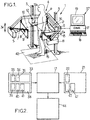
- Figure 1 shows a radiographic apparatus 1 for three-dimensional reconstruction, the apparatus comprising a moving frame 2 displaceable under motor drive along vertical guides 3 in both directions of translation 3a.
- the frame surrounds a field of observation 4 in which a patient P may be placed in a given position, e.g. standing, for observing an osteo-articular structure of the patient when in the standing position, which may be relevant for patients suffering from postural imbalance for example.
- a patient P may be placed in a given position, e.g. standing, for observing an osteo-articular structure of the patient when in the standing position, which may be relevant for patients suffering from postural imbalance for example.
- the moving frame 2 carries a first radiological source 5 and a first detector 6 which is placed facing the source 5 beyond the field 4, and which comprises at least one horizontal line 6a of detector cells.
- the detector 6 may be a gas detector responsive to low doses of radiation, e.g. as described in documents FR-A-2 749 402 or FR-A-2 754 068 .
- other types of detectors may optionally be used in the context of the present invention.
- the radiological source 5 is adapted to emit ionizing radiation, in particular X-rays, suitable for being detected by the detector 6 in an image-taking direction 7 that is antero-posterior relative to the patient P, the rays passing through a horizontal slit 8 made through an aiming mask 9 such as a metal plate in order to generate a horizontal beam 10 of ionizing radiation in the field of observation 4.
- ionizing radiation in particular X-rays
- the moving frame 2 also carries a second radiological source 11 similar to the source 5 and a second detector 12 similar to the detector 6, disposed facing the source 11 beyond the field 4, and comprising at least one horizontal line 12a of detector cells.
- the radiological source 11 is adapted to emit ionizing radiation in a image-taking direction 13 that is lateral relative to the patient P, passing through a horizontal slit 14 formed in an aiming mask 15 such as a metal plate in order to generate a horizontal beam 16 of ionizing radiation in the field of observation 4.
- radiological sources and detectors there could be more than two radiological sources and detectors, and the image-taking directions of these various radiological sources could, where appropriate, be other than mutually perpendicular, and they need not even be horizontal.
- One or each source 5, 11 can be made to emit a beam of X-rays distributed on two different energy peaks, for example by the use of different filters.
- the source 5 emits a beam of low energy and a beam of high energy alternately during the vertical scanning.
- the obtained image carries both high energy and low energy acquisition.
- the patient P is standing on a force-platform 42 which enables to provide the weight and the position of the gravity line of the patient.
- the weight data of the patient could be measured by a separate device, before the patient steps into the radiographic apparatus.
- the two detectors 6, 12 are connected to a computerized system 37 or some other electronic control system provided with:
- the computerized system 37 may also be connected to the motor-driven drive means (not shown) contained in the guide 3, and to the sources 5 and 11, so as to control the vertical displacement of the frame and/or the emission of ionizing radiation.
- the method which is described below is a method of obtention of a finite-element model of a vertebra using a knowledge base of vertebrae.
- this method could be used for any bone or osteo-articular structure of the body such as for example, the femur, the upper limb, the lower limb, the hip, or even part or totality of the skeleton, when a knowledge base of the structure to be reconstructed is provided.
- the processor 17 is connected to a detection memory 33 comprising detection data of the patient P.
- the detection data of the patient P comprises detection data 34 of the bone structure of the patient, such as, for example, antero-posterior 35 and lateral 36 (possibly dual-energy) X-ray images of the patient taken with the apparatus 1.
- the detection data can further comprise external detection data 38 of the patient such as, for example, antero-posterior 39 and lateral 40 detection of the external envelope (skin) of the patient detected on the antero-posterior and lateral radiographs, respectively, and/or, for example, data of the 3D envelope of the patient and/or weight data 41 of the patient, for example provided from the force platform 42.
- the processor 17 is further connected to a knowledge base memory 21 comprising a knowledge base 22 of the geometry of the bone structure, a knowledge base 43 related to the mass and the location of the center of gravity of patient body segments with regard to the bone(s) of interest, and a knowledge base 47 of bone mechanical characteristics.
- a knowledge base memory 21 comprising a knowledge base 22 of the geometry of the bone structure, a knowledge base 43 related to the mass and the location of the center of gravity of patient body segments with regard to the bone(s) of interest, and a knowledge base 47 of bone mechanical characteristics.
- the processor 17 calculates, from the detection data and the knowledge base a patient-specific position-specific finite-element model (FEM) which can be used in an appropriate FEM-solver 44.
- FEM finite-element model
- the detection memory 33, the processor 17, the knowledge base memory 21 and the FEM-solver 44 could be found on the same computerized system, or distributed over a network.
- the knowledge database may be constructed as or from data obtained from similar structures.
- the geometry knowledge database 22 is arranged so as to store surface data relating to coordinates of points belonging to a surface of a generic model.
- the surface data comprise information about points corresponding to particular reference marks on structures of the same type of the studied structure, acquired beforehand, for example by computer tomography.
- the geometry knowledge database 22 of the vertebra contains the coordinates x P1 , y P1 , Z P1 ,..., x P23 , y P23 , Z p23 , of characteristic points P1,..,P23 for the vertebra of each of a plurality of previous patients, characteristic lengths D1..D8 for each vertebra, as shown in Fig. 3 , segments, straight lines or arcs that are characteristics of the object, and/or outlines and edges of these particular vertebra.
- the coordinates of characteristic points or lines may be expressed, for example, in a local X, Y, Z frame of reference.
- outer and inner surface data may further comprise a mesh of several hundred to several hundred thousand points and/or elements of an average vertebra.
- the vertebral mesh may be obtained from a mathematical model constructed from the previously acquired data.
- the surface data may include statistical data (means, variances%) for each parameter of the knowledge base.
- the surface data may include mathematical equations for determining from the knowledge base of a given vertebra, the positions of the characteristic points for a personalised mesh on the basis of values of estimator parameters for said object.
- the coordinates of the characteristic points may be parameterized by functions of these parameters.
- data represents as well raw data such as obtained from measurements of similar structures, and elaborated data such as equations or the like obtained from the observation of such measurements.
- data is used to represent any knowledge which can be stored on a medium and relate to the studied structure.
- the mechanical characteristic knowledge data base 47 can for example have been previously obtained from imaging samples from anatomical specimen by X-rays, so as to determine the grey-level of the sample (the bone's mineral density), then by determining in vitro the bone's mechanical properties by mechanical testing (compression, traction and/or bending tests), so as to correlate the grey level and the mechanical characteristics of the sample.
- the computer 37 is used initially to take two radiographic images of the patient P by causing the field of observation 4 to be scanned by the beams 10 and 16 of ionizing radiation over a height corresponding to the structure of the patient that is to be observed, for example the spine and the pelvis, or indeed the entire skeleton.
- the frame is displaceable for example over the height of the patient.
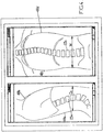
- Fig. 4 is just an illustrative schematic representation of radiographs, which are grey-levelled images.
- the processor 17 receives two-dimensional patient-specific detection data 35, 36, i.e. the two radiographic images of the patient P.
- the processor 17 comprises or communicates with the memory 21 that stores the knowledge database of the structure 22 shown in Fig.2 .
- the processor selects an initial model in the geometry knowledge database 22 of the bone from the detection data 35, 36.
- the selection step may take into account parameters such as a previous radiography of a same patient, a knowledge of the part of the patient that is being imaged etc. to identify an initial model.
- the selection step is performed by an operator, who selects an initial model, and might also point out parts 23a, 23b of the images corresponding to the model.
- the method is to be used for imaging a single type of structure, e.g. femurs, and the base 22 may contain data relative to a single model, e.g. of an healthy femur.
- the selection step is trivial.
- the invention is by no means limited by the implementation of the selection step.
- the 3D outer surfacic model could be obtained by already known methods such as the one described in Laporte et al. "A Biplanar Reconstruction Method Based on 2D and 3D Contours: Application to the Distal Femur", Computer Methods in Biomechanics and Biomedical Engineering 6(1), 1-6, 2003 .
- a three-dimensional position-specific patient-specific surfacic geometric model of the bone structure of the patient is thereby obtained in the frame of reference of the imager.
- This model is represented as a mesh comprising, for example, surfacic shell elements 46, for representing the cortical bone.
- the inside volume can be meshed with internal (not shown) volumic elements, for representing the trabecular bone.
- the model is obtained in the frame of reference of the imager, i.e. corresponds to the actual position of the patient when taking the image.
- patient-specific bone mechanical properties e.g. Young's modulus, maximum compressive or tensile strength
- Further parameters such as those related to the anisotropy of the bone material could also be defined. These parameters could be defined individually for each element of the mesh or for parts of the model having, in average, the same mechanical behaviour.
- the mechanical property knowledge database 47 is used to correlate the information provided from the detection data, such as the grey level in the radiographic images, to the mechanical characteristics of the bone.
- a thickness value and a value of the Young's modulus are defined from the mechanical characteristics knowledge base 47.
- uniform thickness and Young's modulus data are defined over the model elements, based on average thickness and Young's modulus data provided from the mechanical characteristics knowledge base 47.
- different initial values could be defined for different anatomical regions such as the anterior, lateral, and posterior vertebral walls, the pedicle, etc.
- the initial mechanical characteristics inserted into the geometric model can be modified to be made patient-specific. For example, if we take into account the fact that the grey level on the image is related both to attenuation coefficient of the tissues (which is also related density and thus to elastic modulus) and cortical thickness. We can simulate virtual X-rays according to the initial attenuation/thickness and we can change those initial parameters until the simulated radiographs are made as similar as possible to the real radiographs. This step will lead to patient-specific mechanical properties.
- the above is just an example of how to determine the patient's specific geometry and mechanical characteristics.
- the mechanical characteristics could be determined simultaneously with the determination of the geometry, by using the mechanical characteristics already during the reconstruction step.
- the cortical bone could also be meshed with volumic elements.
- the patient-specific position-specific mechanical loads applied to the bone structure in the position of the patient when taking the acquisition data are estimated. For example, these loads are due to gravity.
- the patient-specific mechanical loads can be assessed from any suitable kind of mechanical model.
- the body is virtually divided into segments, such as the head, each upper limb, the trunk, and each of the lower limbs.
- the trunk segment could be divided in sub-segments, for example at each vertebral level and at the pelvis level.
- the mass and position of the centre of gravity is determined from the geometry at that level.
- the knowledge base 43 related to the mass and location of the centre of gravity of the body segments comprise an anthropometric table enabling to estimate, from the local geometry, the mass and the location of the centre of gravity of the studied segment or sub-segment.
- the local geometry could for example be the bone geometry obtained from the radiographs or from the previously obtained mesh, for example.
- the location of the centre of gravity and the mass of the sub-segment can be statistically determined from the knowledge base 43 based only on the location of the bone in one, or both radiographs or on the 3D mesh.
- the location of the centre of gravity and the mass of the sub-segment can be statistically determined using additional data 39, 40 relating to the external envelope of the patient at the sub-segment.
- the knowledge base 43 comprises knowledge enabling to determine, for a given envelope, the location of the centre of gravity and the mass of each corporal sub-segment situated above the bony structure of interest.
- parts of the patient's envelope are determined.
- the back and front outlines 48a, 48b of the skin of the patient are detected on the lateral radiographs, and left and right outlines 48c, 48d on the frontal radiograph.
- These outlines could be determined, either automatically by image processing, or manually by the user.
- the lateral depth between the front and back envelope is measured as shown by arrow D L on Figure 4
- the width between the left and right envelopes is measured, as shown (for another sub-segment) by arrow W on Fig. 4 .
- the knowledge base 43 comprises a priori knowledge of the average density of the sub-segment which allows calculating the mass and the position of the centre of gravity of this sub-segment, as a function of depth and width. This a priori knowledge is used, together with the patient specific measurements, to determine the patient-specific position of the sub-segment's centre of gravity and its mass.
- This average density might not distinguish density values for bone and soft tissue and, in this case, is an overall density for the sub-segment.
- the stored density might distinguish between average soft tissue density and average bone density.
- This determination is performed for all the sub-segments and segments above the studied structure, so as to evaluate the location and intensity of the gravitational load on the studied structure, by calculating the barycentre of all the segments above the structure.
- the medical imager could comprise an optical acquisition device, such as one or more cameras, the images of which can be determined in the same three-dimensional frame of reference as the one of the geometrical 3D model, of the studied structure so as to reconstruct a full 3D envelope.
- An embodiment could use the projection of structured light onto the patient, detection of this light by cameras, and the processing of the detected optical images by suitable well-known algorithms.
- the envelope data is used to determine, in the imaging position (here : standing), the point of application of the gravitational load of the part of the patient situated above the bone structure of which a 3-dimensional reconstruction has been previously established.
- the total mass 41 of the patient could also be used for the determination of the mass and the location of the centre of gravity of the sub-segment.
- the mass and the location of the centre of gravity of the segments under the studied structure could be determined using any of the above methods. Then, the mass and the location of the centre of gravity of the part above the studied structure could be determined therefrom and from the data provided from the force platform 42, by an equilibrium calculation.
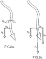
- the applied load F g on the bone structure is calculated by the total mass above the bone structure, applied on the centre of mass G of the portions of the patient above the bone structure, and along the vertical direction. It is thus shown on Fig. 6a that the gravity load for a given vertebra is applied at a distance Dg from the vertebra, whereby a moment Mg is applied on the vertebra. As shown on Fig. 6b , this moment can be regulated by a muscular force F m , which is applied at a distance Dm from the vertebra. F g and F m build up the total resultant force F v applied on the vertebra.
- More complex models can be used. Taking into account the muscles lever arms (the distance between the gravity line and the bone and the distance between muscle attachments and the bone) it is possible to estimate the loads on the bone. Such mechanical model could be improved using a multiple muscles regulation model.
- a proprioception based regulation model can be proposed to estimate the trunk muscular loads.
- the muscular model is built as a closed loop regulation system considering the load components within the intervertebral joint as the commands that have to be maintained beyond given thresholds, such as described for example in " A proprioception based regulation model to estimate the trunk muscular forces", Pomero and al., Computer Methods in Biomechanics and Biomedical Engineering, Vol. 7, No 6, December 2004, pages 331-338 .
- the initial mesh of the generic model could bear information of the nodes or elements which are to be considered as muscle insertion points into the bone. Upon deforming the initial mesh to be rendered patient-specific, these nodes and elements are displaced and/or deformed, which provides with a patient-specific location of muscle insertion.
- arrows 51 represent the intensity of forces exerted by the muscles 52 in the sectional view, as determined from the muscular model.
- the resulting force 53 and torque 54 at the bone joint are also shown on Fig. 7.
- Fig. 7 is a purely illustrative view of the muscular loads determined by the muscular model, but is not a view obtained from the medical imager of Figure 1 .
- the thereby determined loads are expressed in the same frame of reference as the 3D patient-specific mesh with personalised mechanical characteristics.
- the thus obtained patient-specific and position-specific finite-element model is input in a finite element solver 44, which solves the mechanical problem for the model.
- the results can be displayed on the screen 19, for example in pseudo-colours, such as schematically illustrated on Fig. 8 , on which a level of stress experienced by the patient in the standing position in which he was imaged is represented. The highest stress is found in region 50 1 . Decreasing stresses are encountered in regions 50 2 , 50 3 ,..., 50 k ,.... These results could allow a clinician to visualize on which part of the bone the applied mechanical load has a critical effect in the functional position in which the patient was imaged.
- Automatic post-processing could be made to determine biomechanically relevant parameters, such as, for example, the highest stress or highest strain encountered in an element, an average stress in a given part of the bone model, a number of contiguous elements having a stress or strain above a predetermined threshold, or any preestablished biomechanical criteria.
- biomechanical parameters could be taken into account by the clinician to determine a risk of fracture for the patient, for example osteoporotic patients and/or to propose a therapy.
- the structure to be studied could be a single bone or a whole osteo-articular structure and could be any part of the body skeleton of a patient, either in a lying or standing position or any other functional position in which gravity induces a critical load on the bone structure (squatting, standing carrying a load,).
- the acquisition scheme is not limited to the one presented in relation to Fig. 1 , wherein a lateral and an antero-posterior images of the structure are obtained simultaneously.
- the platen 29 will be movable relative to the radiological source in order to take a plurality of images of the patient standing on the platen along different orientations. It is even estimated that the present method could be performed using, as detection data, either a pair of non-calibrated radiographs, or a single radiograph.
Landscapes
- Health & Medical Sciences (AREA)
- Public Health (AREA)
- Engineering & Computer Science (AREA)
- Medical Informatics (AREA)
- Primary Health Care (AREA)
- General Health & Medical Sciences (AREA)
- Epidemiology (AREA)
- Data Mining & Analysis (AREA)
- Pathology (AREA)
- Databases & Information Systems (AREA)
- Biomedical Technology (AREA)
- Nuclear Medicine, Radiotherapy & Molecular Imaging (AREA)
- Radiology & Medical Imaging (AREA)
- Apparatus For Radiation Diagnosis (AREA)
Description
- The instant invention relates to medical imaging methods and systems for providing a finite-element model.
- When it comes to mechanical structures, the advantages of the finite-element-method are well known. Recently, attempts were made to use this method to simulate the behaviour of body structures, in particular bony structures of a patient as a mechanical system. Such simulations are difficult: it is necessary to obtain a precise geometry of the bony structure, the mechanical properties of the internal body organs, and the applied loads (also called "boundary conditions"). An attempt to provide such a finite-element-model is described in
US 5,172,695 . In this patent, the three-dimensional geometry is obtained using a conventional Computer Tomography scanner. The volumetric image provided by the scanner is also a way to quantify the local mechanical properties, by linking the grey value of the voxel to the bone mineral density, which itself can be correlated to the mechanical characteristics of the bone. Then, a finite-element calculation is performed by applying loads on a bony surface. - There is a need to improve the clinical relevance of such calculations, so that their results could be used by clinicians.
-
US 5172695 discloses a method bone structure data being patient specific so as to determine structure patient specific mechanical characteristics. - To this aim, according to the invention, a method according to claim 1 is provided.
- With these features, it is possible to take into account the position of the patient during the acquisition, so that the applied load used for the calculation corresponds to the one actually applied on the bony structure in this functional position.
- In some embodiments, one might also use one or more of the features defined in the dependent claims. Advantages of some of these embodiments include reduction of the radiation dose applied to the patient.
- Other characteristics and advantages of the invention will readily appear from the following description of two of its embodiments, provided as a non-limitative example, and of the accompanying drawings.
- On the drawings :
-
Fig. 1 is a perspective view of an example of a medical imager according to an embodiment of the invention, -
Fig. 2 is a schematic view of the computerized system ofFig. 1 , -
Fig. 3 is a perspective view of an example of a generic model for use in a method according to an embodiment of the invention, -
Fig. 4 is a schematic view of a computer screen on which detection data is schematically represented, -
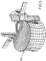
Fig. 5 is a schematic view of an FEM model, -
Fig. 6a and 6b are schematic views with a basic muscular model, illustrating how the loads can be estimated using the patient position-specificity, -
Fig. 7 is a cross-sectional view through a patient, showing a plurality of applied muscular forces illustrating data related to a more sophisticated muscular model, -
Fig. 8 is a schematic view of a result of a FEM calculation for a FEM model such as the one ofFig. 5 , and -
Fig. 9 is a schematic perspective view of another possible embodiment for an installation. - On the different figures, the same reference signs designate like or similar elements.
- The scope of the invention is defined by the appended claims. Other embodiments herein decribed have to be interpreted as examples.
-
Figure 1 shows a radiographic apparatus 1 for three-dimensional reconstruction, the apparatus comprising a movingframe 2 displaceable under motor drive along vertical guides 3 in both directions of translation 3a. - The frame surrounds a field of
observation 4 in which a patient P may be placed in a given position, e.g. standing, for observing an osteo-articular structure of the patient when in the standing position, which may be relevant for patients suffering from postural imbalance for example. - The moving
frame 2 carries a first radiological source 5 and afirst detector 6 which is placed facing the source 5 beyond thefield 4, and which comprises at least onehorizontal line 6a of detector cells. By way of example, thedetector 6 may be a gas detector responsive to low doses of radiation, e.g. as described in documentsFR-A-2 749 402 FR-A-2 754 068 - The radiological source 5 is adapted to emit ionizing radiation, in particular X-rays, suitable for being detected by the
detector 6 in an image-taking direction 7 that is antero-posterior relative to the patient P, the rays passing through ahorizontal slit 8 made through an aiming mask 9 such as a metal plate in order to generate ahorizontal beam 10 of ionizing radiation in the field ofobservation 4. - The moving
frame 2 also carries a secondradiological source 11 similar to the source 5 and asecond detector 12 similar to thedetector 6, disposed facing thesource 11 beyond thefield 4, and comprising at least onehorizontal line 12a of detector cells. - The
radiological source 11 is adapted to emit ionizing radiation in a image-takingdirection 13 that is lateral relative to the patient P, passing through ahorizontal slit 14 formed in an aimingmask 15 such as a metal plate in order to generate ahorizontal beam 16 of ionizing radiation in the field ofobservation 4. - Naturally, there could be more than two radiological sources and detectors, and the image-taking directions of these various radiological sources could, where appropriate, be other than mutually perpendicular, and they need not even be horizontal.
- One or each
source 5, 11 can be made to emit a beam of X-rays distributed on two different energy peaks, for example by the use of different filters. For example, the source 5 emits a beam of low energy and a beam of high energy alternately during the vertical scanning. The obtained image carries both high energy and low energy acquisition. - In the present example, the patient P is standing on a force-
platform 42 which enables to provide the weight and the position of the gravity line of the patient. In another embodiment, the weight data of the patient could be measured by a separate device, before the patient steps into the radiographic apparatus. - The two
detectors computerized system 37 or some other electronic control system provided with: - · an input interface comprising at least a
keyboard 18 and generally also a mouse (not shown); - · an output interface comprising at least a
screen 19; and - · a
processor 17, for executing a computer program adapted to implement the method described herein. - The
computerized system 37 may also be connected to the motor-driven drive means (not shown) contained in the guide 3, and to thesources 5 and 11, so as to control the vertical displacement of the frame and/or the emission of ionizing radiation. - By way of example, the method which is described below is a method of obtention of a finite-element model of a vertebra using a knowledge base of vertebrae. However, this method could be used for any bone or osteo-articular structure of the body such as for example, the femur, the upper limb, the lower limb, the hip, or even part or totality of the skeleton, when a knowledge base of the structure to be reconstructed is provided.
- As an example shown on
Fig. 2 , theprocessor 17 is connected to adetection memory 33 comprising detection data of the patient P. - The detection data of the patient P comprises
detection data 34 of the bone structure of the patient, such as, for example, antero-posterior 35 and lateral 36 (possibly dual-energy) X-ray images of the patient taken with the apparatus 1. In some embodiments, the detection data can further compriseexternal detection data 38 of the patient such as, for example, antero-posterior 39 and lateral 40 detection of the external envelope (skin) of the patient detected on the antero-posterior and lateral radiographs, respectively, and/or, for example, data of the 3D envelope of the patient and/orweight data 41 of the patient, for example provided from theforce platform 42. - The
processor 17 is further connected to aknowledge base memory 21 comprising aknowledge base 22 of the geometry of the bone structure, aknowledge base 43 related to the mass and the location of the center of gravity of patient body segments with regard to the bone(s) of interest, and aknowledge base 47 of bone mechanical characteristics. There are multiple ways in which the knowledge can be stored in the knowledge base(s). - As will be described in more details below, the
processor 17 calculates, from the detection data and the knowledge base a patient-specific position-specific finite-element model (FEM) which can be used in an appropriate FEM-solver 44. Such FEM-solvers are commercially available and will not be described in more details. - The
detection memory 33, theprocessor 17, theknowledge base memory 21 and the FEM-solver 44 could be found on the same computerized system, or distributed over a network. - For the bone structure under study, the knowledge database may be constructed as or from data obtained from similar structures.
- The
geometry knowledge database 22 is arranged so as to store surface data relating to coordinates of points belonging to a surface of a generic model. - In this example, the surface data comprise information about points corresponding to particular reference marks on structures of the same type of the studied structure, acquired beforehand, for example by computer tomography.
- By way of example, the
geometry knowledge database 22 of the vertebra contains the coordinates xP1, yP1, ZP1,..., xP23, yP23, Zp23, of characteristic points P1,..,P23 for the vertebra of each of a plurality of previous patients, characteristic lengths D1..D8 for each vertebra, as shown inFig. 3 , segments, straight lines or arcs that are characteristics of the object, and/or outlines and edges of these particular vertebra. - As shown in
Fig. 3 , the coordinates of characteristic points or lines may be expressed, for example, in a local X, Y, Z frame of reference. - Further, the outer and inner surface data may further comprise a mesh of several hundred to several hundred thousand points and/or elements of an average vertebra.
- It is possible to establish a subset (not represented) of the knowledge database related to vertebrae belonging to healthy individuals or to individuals suffering from different pathologies, and similarly it is possible to characterize each vertebral mesh as a function of the weight, the size, the age, or any other type of parameter concerning the individual that is deemed to be necessary.
- Alternatively, in a not represented embodiment, the vertebral mesh may be obtained from a mathematical model constructed from the previously acquired data. By way of example, the surface data may include statistical data (means, variances...) for each parameter of the knowledge base. The surface data may include mathematical equations for determining from the knowledge base of a given vertebra, the positions of the characteristic points for a personalised mesh on the basis of values of estimator parameters for said object. For example, the coordinates of the characteristic points may be parameterized by functions of these parameters.
- As used herein, the term "data" represents as well raw data such as obtained from measurements of similar structures, and elaborated data such as equations or the like obtained from the observation of such measurements. The word "data" is used to represent any knowledge which can be stored on a medium and relate to the studied structure.
- The mechanical characteristic
knowledge data base 47 can for example have been previously obtained from imaging samples from anatomical specimen by X-rays, so as to determine the grey-level of the sample (the bone's mineral density), then by determining in vitro the bone's mechanical properties by mechanical testing (compression, traction and/or bending tests), so as to correlate the grey level and the mechanical characteristics of the sample. - Referring back to
Fig. 1 , thecomputer 37 is used initially to take two radiographic images of the patient P by causing the field ofobservation 4 to be scanned by thebeams - During this movement, two calibrated digital radiographic images of the portion of the patient under examination are stored in the
memory 33 of themicrocomputer 37, for example an antero-posterior image and a lateral image respectively, wherein each images can be viewed on thescreen 19 of the microcomputer, as shown schematically inFigure 4 . Of course,Fig. 4 is just an illustrative schematic representation of radiographs, which are grey-levelled images. - The
processor 17 receives two-dimensional patient-specific detection data processor 17 comprises or communicates with thememory 21 that stores the knowledge database of thestructure 22 shown inFig.2 . - The processor selects an initial model in the
geometry knowledge database 22 of the bone from thedetection data - In an alternative embodiment, the selection step is performed by an operator, who selects an initial model, and might also point out
parts 23a, 23b of the images corresponding to the model. - In an alternative embodiment, the method is to be used for imaging a single type of structure, e.g. femurs, and the base 22 may contain data relative to a single model, e.g. of an healthy femur. In this case, the selection step is trivial.
- The invention is by no means limited by the implementation of the selection step.
- The 3D outer surfacic model could be obtained by already known methods such as the one described in Laporte et al. "A Biplanar Reconstruction Method Based on 2D and 3D Contours: Application to the Distal Femur", Computer Methods in Biomechanics and Biomedical Engineering 6(1), 1-6, 2003.
- Although this article is related to the distal femur, the method described there could be used for any other bone structure. This exemplary method could be summarized as follows :
- the initial model is placed in virtual space so as to roughly correspond to the images of the structure,
- anatomical regions are defined on the generic model,
- 2D contours Λj are identified on the radiographs,
- 2D contours Ωj in the plane of the radiographs are generated from the initial model,
- contours Ωj and Λj are associated to one another,
- the initial model is deformed (for example by combination of a rigid transformation and an homothetic transformation) and contours Ωj are calculated for the deformed model, until contours Ωj and Λj fit,
- the deformed model is further deformed so as to be optimized, for example by kriging.
- A three-dimensional position-specific patient-specific surfacic geometric model of the bone structure of the patient is thereby obtained in the frame of reference of the imager. This model is represented as a mesh comprising, for example,
surfacic shell elements 46, for representing the cortical bone. For example, the inside volume can be meshed with internal (not shown) volumic elements, for representing the trabecular bone. In addition, the model is obtained in the frame of reference of the imager, i.e. corresponds to the actual position of the patient when taking the image. - On
Fig. 5 , the patient specific resulting mesh is represented very schematically. - In a further step, patient-specific bone mechanical properties (e.g. Young's modulus, maximum compressive or tensile strength) are input into the model. Further parameters, such as those related to the anisotropy of the bone material could also be defined. These parameters could be defined individually for each element of the mesh or for parts of the model having, in average, the same mechanical behaviour.
- The mechanical
property knowledge database 47 is used to correlate the information provided from the detection data, such as the grey level in the radiographic images, to the mechanical characteristics of the bone. - For example, for each surfacic element of the obtained geometric model, a thickness value and a value of the Young's modulus are defined from the mechanical
characteristics knowledge base 47. For example, initially, uniform thickness and Young's modulus data are defined over the model elements, based on average thickness and Young's modulus data provided from the mechanicalcharacteristics knowledge base 47. - In variant embodiments, different initial values could be defined for different anatomical regions such as the anterior, lateral, and posterior vertebral walls, the pedicle, etc....
- It should be noted that other mechanical parameters could be defined, such as a single parameter combining thickness and Young's modulus (equivalent homogenized modulus for a given thickness).
- The initial mechanical characteristics inserted into the geometric model can be modified to be made patient-specific. For example, if we take into account the fact that the grey level on the image is related both to attenuation coefficient of the tissues (which is also related density and thus to elastic modulus) and cortical thickness. We can simulate virtual X-rays according to the initial attenuation/thickness and we can change those initial parameters until the simulated radiographs are made as similar as possible to the real radiographs. This step will lead to patient-specific mechanical properties.
- The above is just an example of how to determine the patient's specific geometry and mechanical characteristics. The mechanical characteristics could be determined simultaneously with the determination of the geometry, by using the mechanical characteristics already during the reconstruction step.
- In another embodiment, the cortical bone could also be meshed with volumic elements.
- Further, the patient-specific position-specific mechanical loads applied to the bone structure in the position of the patient when taking the acquisition data are estimated. For example, these loads are due to gravity. The patient-specific mechanical loads can be assessed from any suitable kind of mechanical model.
- For example, the body is virtually divided into segments, such as the head, each upper limb, the trunk, and each of the lower limbs. The trunk segment could be divided in sub-segments, for example at each vertebral level and at the pelvis level. For each segment or sub-segment, the mass and position of the centre of gravity is determined from the geometry at that level. For example, the
knowledge base 43 related to the mass and location of the centre of gravity of the body segments comprise an anthropometric table enabling to estimate, from the local geometry, the mass and the location of the centre of gravity of the studied segment or sub-segment. The local geometry could for example be the bone geometry obtained from the radiographs or from the previously obtained mesh, for example. - In this case, the location of the centre of gravity and the mass of the sub-segment can be statistically determined from the
knowledge base 43 based only on the location of the bone in one, or both radiographs or on the 3D mesh. - In another embodiment, the location of the centre of gravity and the mass of the sub-segment can be statistically determined using
additional data - For example, the
knowledge base 43 comprises knowledge enabling to determine, for a given envelope, the location of the centre of gravity and the mass of each corporal sub-segment situated above the bony structure of interest. - In this example, as shown on
Fig. 4 , parts of the patient's envelope are determined. For example, the back andfront outlines right outlines 48c, 48d on the frontal radiograph. These outlines could be determined, either automatically by image processing, or manually by the user. For example, for each sub-segment, the lateral depth between the front and back envelope is measured as shown by arrow DL onFigure 4 , and the width between the left and right envelopes is measured, as shown (for another sub-segment) by arrow W onFig. 4 . Theknowledge base 43 comprises a priori knowledge of the average density of the sub-segment which allows calculating the mass and the position of the centre of gravity of this sub-segment, as a function of depth and width. This a priori knowledge is used, together with the patient specific measurements, to determine the patient-specific position of the sub-segment's centre of gravity and its mass. - This average density might not distinguish density values for bone and soft tissue and, in this case, is an overall density for the sub-segment. In a variant embodiment where bone detection data is available for the sub-segment, the stored density might distinguish between average soft tissue density and average bone density.
- Although the above embodiments describe using both the width and depth of the sub-segment for determining its mass and the location of its centre of gravity, only one of the width and depth could be used, in a variant embodiment for this determination.
- This determination is performed for all the sub-segments and segments above the studied structure, so as to evaluate the location and intensity of the gravitational load on the studied structure, by calculating the barycentre of all the segments above the structure.
- There are many other possible embodiments for obtaining the mass and the location of the centre of gravity. For example, the medical imager could comprise an optical acquisition device, such as one or more cameras, the images of which can be determined in the same three-dimensional frame of reference as the one of the geometrical 3D model, of the studied structure so as to reconstruct a full 3D envelope. An embodiment could use the projection of structured light onto the patient, detection of this light by cameras, and the processing of the detected optical images by suitable well-known algorithms.
- The envelope data is used to determine, in the imaging position (here : standing), the point of application of the gravitational load of the part of the patient situated above the bone structure of which a 3-dimensional reconstruction has been previously established.
- In any of the above embodiments, the
total mass 41 of the patient could also be used for the determination of the mass and the location of the centre of gravity of the sub-segment. - In a variant embodiment, the mass and the location of the centre of gravity of the segments under the studied structure could be determined using any of the above methods. Then, the mass and the location of the centre of gravity of the part above the studied structure could be determined therefrom and from the data provided from the
force platform 42, by an equilibrium calculation. - The applied load Fg on the bone structure is calculated by the total mass above the bone structure, applied on the centre of mass G of the portions of the patient above the bone structure, and along the vertical direction. It is thus shown on
Fig. 6a that the gravity load for a given vertebra is applied at a distance Dg from the vertebra, whereby a moment Mg is applied on the vertebra. As shown onFig. 6b , this moment can be regulated by a muscular force Fm, which is applied at a distance Dm from the vertebra. Fg and Fm build up the total resultant force Fv applied on the vertebra. - There is a whole range of possibilities to determine the muscular load. One might use a simple muscular model in which only one set of muscles is activated.
- More complex models can be used. Taking into account the muscles lever arms (the distance between the gravity line and the bone and the distance between muscle attachments and the bone) it is possible to estimate the loads on the bone. Such mechanical model could be improved using a multiple muscles regulation model. For example a proprioception based regulation model can be proposed to estimate the trunk muscular loads. The muscular model is built as a closed loop regulation system considering the load components within the intervertebral joint as the commands that have to be maintained beyond given thresholds, such as described for example in "A proprioception based regulation model to estimate the trunk muscular forces", Pomero and al., Computer Methods in Biomechanics and Biomedical Engineering, Vol. 7, No 6, December 2004, pages 331-338.
- The initial mesh of the generic model could bear information of the nodes or elements which are to be considered as muscle insertion points into the bone. Upon deforming the initial mesh to be rendered patient-specific, these nodes and elements are displaced and/or deformed, which provides with a patient-specific location of muscle insertion.
- As shown on
Fig. 7 ,arrows 51 represent the intensity of forces exerted by themuscles 52 in the sectional view, as determined from the muscular model. The resultingforce 53 andtorque 54 at the bone joint are also shown onFig. 7. Fig. 7 is a purely illustrative view of the muscular loads determined by the muscular model, but is not a view obtained from the medical imager ofFigure 1 . - The thereby determined loads are expressed in the same frame of reference as the 3D patient-specific mesh with personalised mechanical characteristics.
- Finally, the applied loads are input into the finite-element model as shown by arrow Fv on
Fig. 6b . The above are just examples of possible patient-specific loads and only examples of how to measure them. - The thus obtained patient-specific and position-specific finite-element model is input in a
finite element solver 44, which solves the mechanical problem for the model. The results can be displayed on thescreen 19, for example in pseudo-colours, such as schematically illustrated onFig. 8 , on which a level of stress experienced by the patient in the standing position in which he was imaged is represented. The highest stress is found in region 501. Decreasing stresses are encountered in regions 502, 503,..., 50k,.... These results could allow a clinician to visualize on which part of the bone the applied mechanical load has a critical effect in the functional position in which the patient was imaged. Automatic post-processing could be made to determine biomechanically relevant parameters, such as, for example, the highest stress or highest strain encountered in an element, an average stress in a given part of the bone model, a number of contiguous elements having a stress or strain above a predetermined threshold, or any preestablished biomechanical criteria. - These biomechanical parameters could be taken into account by the clinician to determine a risk of fracture for the patient, for example osteoporotic patients and/or to propose a therapy.
- The method which was described above was by way of example only. The structure to be studied could be a single bone or a whole osteo-articular structure and could be any part of the body skeleton of a patient, either in a lying or standing position or any other functional position in which gravity induces a critical load on the bone structure (squatting, standing carrying a load,...).
- In particular, the acquisition scheme is not limited to the one presented in relation to
Fig. 1 , wherein a lateral and an antero-posterior images of the structure are obtained simultaneously. One could use other kind of acquisition apparatus, such as the one shown onFig. 9 comprising aplaten 29 and twoposts opaque markers 31 positioned in three-dimensional space so that their detection on the obtaineddetection data 32 will be used for calibrating the images respective to each other. Theplaten 29 will be movable relative to the radiological source in order to take a plurality of images of the patient standing on the platen along different orientations. It is even estimated that the present method could be performed using, as detection data, either a pair of non-calibrated radiographs, or a single radiograph.
Claims (15)
- A method comprising:- providing acquisition data (34, 38) of a patient, comprising at least acquisition data (34) of a bone structure of the patient in a given functional position,- providing a knowledge base (22,43,47), comprising at least data (22) related to structures of the same type as the bone structure of the patient,- determining, at least from said acquisition data, a patient-specific three-dimensional geometry of the bone structure,- determining, from said acquisition data and said knowledge base, patient-specific mechanical characteristics of the bone structure,- determining, at least from the acquisition data, a patient-specific position-specific mechanical load (F) applied to the bone structure in said functional given position,- assembling the three-dimensional geometry, the mechanical characteristics and the mechanical load into a patient-specific position-specific finite-element model of the bone structure.
- Method according to claim 1 further comprising one of the following features:- the knowledge database comprises at least data related to the three-dimensional geometry of structures of the same type as the structure of the patient, and wherein the patient-specific three-dimensional geometry is determined using the knowledge base;- the knowledge database comprises at least data related to the mechanical characteristics of structures of the same type as the structure of the patient.
- Method according to any preceding claim wherein the knowledge database comprises at least data related to mass and/or location of a centre of mass of body segments, and wherein the patient-specific position-specific mechanical load is determined using the knowledge base; and optionally wherein acquisition data further comprise acquisition data (39, 40) of at least a part of the external envelope of the patient,
wherein the knowledge base further comprise data (43) related to mass and/or location of a centre of mass correlated to external envelopes. - A method according to any preceding claim, wherein providing acquisition data further comprises providing the weight of the patient.
- A method according to any preceding claim, wherein the mechanical load (F) comprises the load of the mass of the patient situated above the bone structure in said functional position; and optionally wherein the mechanical load further comprises a muscular load applied to the bone structure.
- A method according to any preceding claim further comprising at least one of the following features:- acquisition data of the bone structure comprises at least one bi-dimensional image (35) of the bone structure, and wherein the knowledge base comprises at least data (47) related to the mechanical characteristics of bone structures of the same type as the bone structure of the patient;- acquisition data of the bone structure comprises at least one bi-dimensional image (35) of the bone structure, and the patient-specific three-dimensional geometry is obtained by fitting a generic three-dimensional mesh (20) of the bone structure to the image, said 3D mesh comprising at least one 3D surface.
- A method according to claim 6, and further comprising one or more of the following features:- acquisition data of the bone structure comprises at least two bi-dimensional images (35, 36) of the bone structure taken along two non-parallel directions, and referenced in the same reference frame;- the images are X-ray images.
- A method according to any preceding claim, further comprising a step of placing the patient in the given functional position in a medical imager, and of acquiring at least said acquisition data of the bony structure; and optionally further comprising a step of detecting a part of the external envelope (48a) of the patient in said given functional position.
- A method according to any preceding claim, further comprising applying a finite-element-method solver (44) to the patient-specific position-specific model; and optionally comprising determining with the finite-element-method solver (44) a biomechanical criteria of the bone structure.
- Computer program product comprising instructions for causing a programmable unit to perform the method of any of the preceding claims when executed on said programmable unit.
- A system comprising:- a medical imager (1) adapted to provide acquisition data of a patient, comprising at least acquisition data of a bone structure of the patient in a given functional position,- a knowledge base (22, 43, 47), comprising at least data related to structures of the same type as the structure of the patient,- a computerized unit (37) adapted to determine, from said acquisition data a patient-specific three-dimensional geometry of the bone structure,wherein the computerized unit (37) is further adapted to determine from the acquisition data and said knowledge base, a patient-specific mechanical characteristics of the bone structure,
wherein the computerized unit (37) is further adapted to determine, at least from the acquisition data a patient-specific position-specific mechanical load applied to the bone structure in said given functional position,
wherein the computerized unit (37) is further adapted to assemble the three-dimensional geometry, the mechanical characteristics and the mechanical load into a patient-specific position-specific finite-element model of the bone structure. - A system according to claim 11 further comprising a finite-element-method solver (44) adapted to be applied to the patient-specific position-specific finite-element model.
- A system according to claim 11 or 12 wherein the imager comprises at least a first X-ray source (5), a first X-ray detector (6), and a patient-receiving space adapted to receive the patient in standing position between the first source and the first detector, said detector being adapted to detect said acquisition data of the bone structure of the patient; and optionally comprising at least one of the following features:- the first X-ray source and the first X-ray detector are aligned along a first direction, the imager further comprising a second X-ray source (11) and a second X-ray detector (12) aligned along a second direction not parallel with the first direction;- the system comprises a displacement device adapted for moving said sources and detectors along a third direction in order to scan the patient.
- A system according to any of claims 11 to 13, wherein the medical imager further comprises a force platform (42) adapted to detect the gravity axis passing through the patient.
- A system according to any of claims 11 to 13, wherein the medical imager further comprises at least one camera for detecting at least part of the external envelope of the patient.
Applications Claiming Priority (1)
| Application Number | Priority Date | Filing Date | Title |
|---|---|---|---|
| PCT/IB2008/051807 WO2009106937A1 (en) | 2008-02-29 | 2008-02-29 | Medical imaging method and system for providing a finite-element model |
Publications (2)
| Publication Number | Publication Date |
|---|---|
| EP2245569A1 EP2245569A1 (en) | 2010-11-03 |
| EP2245569B1 true EP2245569B1 (en) | 2020-08-12 |
Family
ID=39929817
Family Applications (1)
| Application Number | Title | Priority Date | Filing Date |
|---|---|---|---|
| EP08789145.3A Not-in-force EP2245569B1 (en) | 2008-02-29 | 2008-02-29 | Medical imaging method and system for providing a finite-element model |
Country Status (3)
| Country | Link |
|---|---|
| US (1) | US20110015514A1 (en) |
| EP (1) | EP2245569B1 (en) |
| WO (1) | WO2009106937A1 (en) |
Families Citing this family (25)
| Publication number | Priority date | Publication date | Assignee | Title |
|---|---|---|---|---|
| US8549888B2 (en) | 2008-04-04 | 2013-10-08 | Nuvasive, Inc. | System and device for designing and forming a surgical implant |
| US9225965B2 (en) * | 2008-11-07 | 2015-12-29 | Telecom Italia S.P.A. | Method and system for producing multi-view 3D visual contents |
| WO2013080223A2 (en) * | 2011-12-01 | 2013-06-06 | Tuscano Equipments Private Limited | A device with simultaneous x-ray and infrared image acquisition and processing system for enhanced breast imaging |
| US11207132B2 (en) | 2012-03-12 | 2021-12-28 | Nuvasive, Inc. | Systems and methods for performing spinal surgery |
| US9507912B2 (en) | 2012-08-31 | 2016-11-29 | Nuvectra Corporation | Method and system of simulating a pulse generator on a clinician programmer |
| US9180302B2 (en) | 2012-08-31 | 2015-11-10 | Greatbatch Ltd. | Touch screen finger position indicator for a spinal cord stimulation programming device |
| US9594877B2 (en) | 2012-08-31 | 2017-03-14 | Nuvectra Corporation | Virtual reality representation of medical devices |
| US8868199B2 (en) | 2012-08-31 | 2014-10-21 | Greatbatch Ltd. | System and method of compressing medical maps for pulse generator or database storage |
| US8903496B2 (en) | 2012-08-31 | 2014-12-02 | Greatbatch Ltd. | Clinician programming system and method |
| US10668276B2 (en) | 2012-08-31 | 2020-06-02 | Cirtec Medical Corp. | Method and system of bracketing stimulation parameters on clinician programmers |
| US9615788B2 (en) | 2012-08-31 | 2017-04-11 | Nuvectra Corporation | Method and system of producing 2D representations of 3D pain and stimulation maps and implant models on a clinician programmer |
| US8761897B2 (en) | 2012-08-31 | 2014-06-24 | Greatbatch Ltd. | Method and system of graphical representation of lead connector block and implantable pulse generators on a clinician programmer |
| US8812125B2 (en) | 2012-08-31 | 2014-08-19 | Greatbatch Ltd. | Systems and methods for the identification and association of medical devices |
| US9471753B2 (en) | 2012-08-31 | 2016-10-18 | Nuvectra Corporation | Programming and virtual reality representation of stimulation parameter Groups |
| US9375582B2 (en) | 2012-08-31 | 2016-06-28 | Nuvectra Corporation | Touch screen safety controls for clinician programmer |
| US9259577B2 (en) | 2012-08-31 | 2016-02-16 | Greatbatch Ltd. | Method and system of quick neurostimulation electrode configuration and positioning |
| US8983616B2 (en) | 2012-09-05 | 2015-03-17 | Greatbatch Ltd. | Method and system for associating patient records with pulse generators |
| US8757485B2 (en) | 2012-09-05 | 2014-06-24 | Greatbatch Ltd. | System and method for using clinician programmer and clinician programming data for inventory and manufacturing prediction and control |
| US9767255B2 (en) | 2012-09-05 | 2017-09-19 | Nuvectra Corporation | Predefined input for clinician programmer data entry |
| CN110123448A (en) | 2013-10-09 | 2019-08-16 | 纽文思公司 | The method for being designed in art during vertebra program of performing the operation and evaluating spine malformation correction |
| US9848922B2 (en) | 2013-10-09 | 2017-12-26 | Nuvasive, Inc. | Systems and methods for performing spine surgery |
| EP3157425A4 (en) | 2014-06-17 | 2017-11-15 | Nuvasive, Inc. | Systems and methods for planning, performing, and assessing spinal correction during surgery |
| US10433893B1 (en) | 2014-10-17 | 2019-10-08 | Nuvasive, Inc. | Systems and methods for performing spine surgery |
| FR3035991B1 (en) * | 2015-05-07 | 2021-01-29 | Arts | PROCESS FOR GENERATING A VIRTUAL MODEL IN THREE DIMENSIONS OF AT LEAST ONE PART OF A SKELETON OF AN INDIVIDUAL |
| CN106598683B (en) * | 2016-12-23 | 2020-09-15 | 武大吉奥信息技术有限公司 | Method and device for quickly loading model data in GIS (geographic information System) large scene |
Family Cites Families (7)
| Publication number | Priority date | Publication date | Assignee | Title |
|---|---|---|---|---|
| US5172695A (en) * | 1990-09-10 | 1992-12-22 | Cann Christopher E | Method for improved prediction of bone fracture risk using bone mineral density in structural analysis |
| FR2749402B1 (en) * | 1996-05-29 | 1998-08-07 | Charpak Georges | HIGH RESOLUTION RADIOGRAPHIC IMAGING DEVICE |
| US8195434B2 (en) * | 2001-09-12 | 2012-06-05 | The Boeing Company | System and method for generating finite element models |
| FR2856170B1 (en) * | 2003-06-10 | 2005-08-26 | Biospace Instr | RADIOGRAPHIC IMAGING METHOD FOR THREE-DIMENSIONAL RECONSTRUCTION, DEVICE AND COMPUTER PROGRAM FOR IMPLEMENTING SAID METHOD |
| GB0404269D0 (en) * | 2004-02-26 | 2004-03-31 | Leuven K U Res & Dev | Time-dependent three-dimensional musculo-skeletal modeling based on dynamic surface measurements of bodies |
| JP4826459B2 (en) * | 2006-01-12 | 2011-11-30 | 株式会社豊田中央研究所 | Musculoskeletal model creation method, human stress / strain estimation method, program, and recording medium |
| FR2909791B1 (en) * | 2006-12-07 | 2009-02-13 | Ecole Nale Sup Artes Metiers | METHOD FOR SIMULATING THE BEHAVIOR OF AN ARTICULATED BONE ASSEMBLY |
-
2008
- 2008-02-29 US US12/919,857 patent/US20110015514A1/en not_active Abandoned
- 2008-02-29 EP EP08789145.3A patent/EP2245569B1/en not_active Not-in-force
- 2008-02-29 WO PCT/IB2008/051807 patent/WO2009106937A1/en not_active Ceased
Non-Patent Citations (1)
| Title |
|---|
| None * |
Also Published As
| Publication number | Publication date |
|---|---|
| EP2245569A1 (en) | 2010-11-03 |
| WO2009106937A1 (en) | 2009-09-03 |
| US20110015514A1 (en) | 2011-01-20 |
Similar Documents
| Publication | Publication Date | Title |
|---|---|---|
| US20110015514A1 (en) | Medical imaging method and system for providing a finite-element model | |
| JP5426170B2 (en) | Estimating the risk of future fractures using a three-dimensional bone density model | |
| US9142020B2 (en) | Osteo-articular structure | |
| US7801350B2 (en) | Method for absorptiometry radiographic imaging using a three-dimensional generic model | |
| EP2149123B1 (en) | Method for reconstruction of a three-dimensional model of a body structure | |
| Testi et al. | Risk of fracture in elderly patients: a new predictive index based on bone mineral density and finite element analysis | |
| EP3461412B1 (en) | System and method for dxa tomo-based finite element analysis of bones | |
| EP2578155A1 (en) | X-ray calibration device | |
| Bagheri et al. | Reliability of three-dimensional spinal modeling of patients with idiopathic scoliosis using EOS system | |
| Lee et al. | Measurement of body segment parameters using dual energy X-ray absorptiometry and three-dimensional geometry: an application in gait analysis | |
| Kadoury et al. | Three-dimensional reconstruction of the scoliotic spine and pelvis from uncalibrated biplanar x-ray images | |
| Le Bras et al. | Three-dimensional (3D) detailed reconstruction of human vertebrae from low-dose digital stereoradiography | |
| Jan et al. | Low-dose computed tomography: a solution for in vivo medical imaging and accurate patient-specific 3D bone modeling? | |
| Pattijn et al. | Structural and radiological parameters for the nondestructive characterization of trabecular bone | |
| Gong et al. | The relationship between orthopedic clinical imaging and bone strength prediction | |
| Sapin et al. | Bone mineral density assessment using the EOS® low-dose X-ray device: A feasibility study | |
| KR20160126195A (en) | Method, System and Computer Program for Bone Modelling via X-Ray Image Processing using Computer | |
| Falcinelli et al. | The effect of computed tomography current reduction on proximal femur subject-specific finite element models | |
| Branni | Constitutive models of bone: The human femur | |
| García-Ruesgas et al. | Projective geometric model for automatic determination of X-ray-emitting source of a standard radiographic system | |
| Haverfield | Quantifying variation in human rib volumetric bone mineral density (vbmd) and its relationship to fracture | |
| Chen | Verification and validation of microCT-based finite element models of bone tissue biomechanics | |
| EP3756546A1 (en) | Bone trabeculae index for x-ray dark-field radiography | |
| Templeton | Three-dimensional biomechanical modeling of vertebrae from radiographs | |
| Urriolagoitia-Sosa et al. | an Anisotropic Elastic FE-Model Based on Swine Femoral Bones Using Numerical Modeling |
Legal Events
| Date | Code | Title | Description |
|---|---|---|---|
| PUAI | Public reference made under article 153(3) epc to a published international application that has entered the european phase |
Free format text: ORIGINAL CODE: 0009012 |
|
| 17P | Request for examination filed |
Effective date: 20100818 |
|
| AK | Designated contracting states |
Kind code of ref document: A1 Designated state(s): AT BE BG CH CY CZ DE DK EE ES FI FR GB GR HR HU IE IS IT LI LT LU LV MC MT NL NO PL PT RO SE SI SK TR |
|
| AX | Request for extension of the european patent |
Extension state: AL BA MK RS |
|
| DAX | Request for extension of the european patent (deleted) | ||
| STAA | Information on the status of an ep patent application or granted ep patent |
Free format text: STATUS: EXAMINATION IS IN PROGRESS |
|
| 17Q | First examination report despatched |
Effective date: 20170323 |
|
| REG | Reference to a national code |
Ref country code: DE Ref legal event code: R079 Ref document number: 602008063137 Country of ref document: DE Free format text: PREVIOUS MAIN CLASS: G06F0019000000 Ipc: G16H0030200000 |
|
| RIC1 | Information provided on ipc code assigned before grant |
Ipc: G16H 30/20 20180101AFI20191216BHEP Ipc: G16H 50/50 20180101ALI20191216BHEP |
|
| GRAP | Despatch of communication of intention to grant a patent |
Free format text: ORIGINAL CODE: EPIDOSNIGR1 |
|
| STAA | Information on the status of an ep patent application or granted ep patent |
Free format text: STATUS: GRANT OF PATENT IS INTENDED |
|
| INTG | Intention to grant announced |
Effective date: 20200302 |
|
| RAP1 | Party data changed (applicant data changed or rights of an application transferred) |
Owner name: CENTRE NATIONAL DE LA RECHERCHE SCIENTIFIQUE (C.N.R.S.) Owner name: ECOLE NATIONALE SUPERIEURE D'ARTS ET METIERS (ENSAM) |
|
| GRAS | Grant fee paid |
Free format text: ORIGINAL CODE: EPIDOSNIGR3 |
|
| GRAA | (expected) grant |
Free format text: ORIGINAL CODE: 0009210 |
|
| STAA | Information on the status of an ep patent application or granted ep patent |
Free format text: STATUS: THE PATENT HAS BEEN GRANTED |
|
| AK | Designated contracting states |
Kind code of ref document: B1 Designated state(s): AT BE BG CH CY CZ DE DK EE ES FI FR GB GR HR HU IE IS IT LI LT LU LV MC MT NL NO PL PT RO SE SI SK TR |
|
| REG | Reference to a national code |
Ref country code: GB Ref legal event code: FG4D |
|
| REG | Reference to a national code |
Ref country code: CH Ref legal event code: EP |
|
| REG | Reference to a national code |
Ref country code: IE Ref legal event code: FG4D |
|
| REG | Reference to a national code |
Ref country code: DE Ref legal event code: R096 Ref document number: 602008063137 Country of ref document: DE |
|
| REG | Reference to a national code |
Ref country code: AT Ref legal event code: REF Ref document number: 1302340 Country of ref document: AT Kind code of ref document: T Effective date: 20200915 |
|
| REG | Reference to a national code |
Ref country code: LT Ref legal event code: MG4D |
|
| REG | Reference to a national code |
Ref country code: NL Ref legal event code: MP Effective date: 20200812 |
|
| PG25 | Lapsed in a contracting state [announced via postgrant information from national office to epo] |
Ref country code: SE Free format text: LAPSE BECAUSE OF FAILURE TO SUBMIT A TRANSLATION OF THE DESCRIPTION OR TO PAY THE FEE WITHIN THE PRESCRIBED TIME-LIMIT Effective date: 20200812 Ref country code: HR Free format text: LAPSE BECAUSE OF FAILURE TO SUBMIT A TRANSLATION OF THE DESCRIPTION OR TO PAY THE FEE WITHIN THE PRESCRIBED TIME-LIMIT Effective date: 20200812 Ref country code: FI Free format text: LAPSE BECAUSE OF FAILURE TO SUBMIT A TRANSLATION OF THE DESCRIPTION OR TO PAY THE FEE WITHIN THE PRESCRIBED TIME-LIMIT Effective date: 20200812 Ref country code: LT Free format text: LAPSE BECAUSE OF FAILURE TO SUBMIT A TRANSLATION OF THE DESCRIPTION OR TO PAY THE FEE WITHIN THE PRESCRIBED TIME-LIMIT Effective date: 20200812 Ref country code: BG Free format text: LAPSE BECAUSE OF FAILURE TO SUBMIT A TRANSLATION OF THE DESCRIPTION OR TO PAY THE FEE WITHIN THE PRESCRIBED TIME-LIMIT Effective date: 20201112 Ref country code: NO Free format text: LAPSE BECAUSE OF FAILURE TO SUBMIT A TRANSLATION OF THE DESCRIPTION OR TO PAY THE FEE WITHIN THE PRESCRIBED TIME-LIMIT Effective date: 20201112 Ref country code: GR Free format text: LAPSE BECAUSE OF FAILURE TO SUBMIT A TRANSLATION OF THE DESCRIPTION OR TO PAY THE FEE WITHIN THE PRESCRIBED TIME-LIMIT Effective date: 20201113 Ref country code: ES Free format text: LAPSE BECAUSE OF FAILURE TO SUBMIT A TRANSLATION OF THE DESCRIPTION OR TO PAY THE FEE WITHIN THE PRESCRIBED TIME-LIMIT Effective date: 20200812 |
|
| REG | Reference to a national code |
Ref country code: AT Ref legal event code: MK05 Ref document number: 1302340 Country of ref document: AT Kind code of ref document: T Effective date: 20200812 |
|
| PG25 | Lapsed in a contracting state [announced via postgrant information from national office to epo] |
Ref country code: IS Free format text: LAPSE BECAUSE OF FAILURE TO SUBMIT A TRANSLATION OF THE DESCRIPTION OR TO PAY THE FEE WITHIN THE PRESCRIBED TIME-LIMIT Effective date: 20201212 Ref country code: NL Free format text: LAPSE BECAUSE OF FAILURE TO SUBMIT A TRANSLATION OF THE DESCRIPTION OR TO PAY THE FEE WITHIN THE PRESCRIBED TIME-LIMIT Effective date: 20200812 Ref country code: PL Free format text: LAPSE BECAUSE OF FAILURE TO SUBMIT A TRANSLATION OF THE DESCRIPTION OR TO PAY THE FEE WITHIN THE PRESCRIBED TIME-LIMIT Effective date: 20200812 Ref country code: LV Free format text: LAPSE BECAUSE OF FAILURE TO SUBMIT A TRANSLATION OF THE DESCRIPTION OR TO PAY THE FEE WITHIN THE PRESCRIBED TIME-LIMIT Effective date: 20200812 |
|
| PG25 | Lapsed in a contracting state [announced via postgrant information from national office to epo] |
Ref country code: RO Free format text: LAPSE BECAUSE OF FAILURE TO SUBMIT A TRANSLATION OF THE DESCRIPTION OR TO PAY THE FEE WITHIN THE PRESCRIBED TIME-LIMIT Effective date: 20200812 Ref country code: CZ Free format text: LAPSE BECAUSE OF FAILURE TO SUBMIT A TRANSLATION OF THE DESCRIPTION OR TO PAY THE FEE WITHIN THE PRESCRIBED TIME-LIMIT Effective date: 20200812 Ref country code: DK Free format text: LAPSE BECAUSE OF FAILURE TO SUBMIT A TRANSLATION OF THE DESCRIPTION OR TO PAY THE FEE WITHIN THE PRESCRIBED TIME-LIMIT Effective date: 20200812 Ref country code: EE Free format text: LAPSE BECAUSE OF FAILURE TO SUBMIT A TRANSLATION OF THE DESCRIPTION OR TO PAY THE FEE WITHIN THE PRESCRIBED TIME-LIMIT Effective date: 20200812 |
|
| REG | Reference to a national code |
Ref country code: DE Ref legal event code: R097 Ref document number: 602008063137 Country of ref document: DE |
|
| PG25 | Lapsed in a contracting state [announced via postgrant information from national office to epo] |
Ref country code: AT Free format text: LAPSE BECAUSE OF FAILURE TO SUBMIT A TRANSLATION OF THE DESCRIPTION OR TO PAY THE FEE WITHIN THE PRESCRIBED TIME-LIMIT Effective date: 20200812 |
|
| PLBE | No opposition filed within time limit |
Free format text: ORIGINAL CODE: 0009261 |
|
| STAA | Information on the status of an ep patent application or granted ep patent |
Free format text: STATUS: NO OPPOSITION FILED WITHIN TIME LIMIT |
|
| PG25 | Lapsed in a contracting state [announced via postgrant information from national office to epo] |
Ref country code: SK Free format text: LAPSE BECAUSE OF FAILURE TO SUBMIT A TRANSLATION OF THE DESCRIPTION OR TO PAY THE FEE WITHIN THE PRESCRIBED TIME-LIMIT Effective date: 20200812 |
|
| 26N | No opposition filed |
Effective date: 20210514 |
|
| PG25 | Lapsed in a contracting state [announced via postgrant information from national office to epo] |
Ref country code: SI Free format text: LAPSE BECAUSE OF FAILURE TO SUBMIT A TRANSLATION OF THE DESCRIPTION OR TO PAY THE FEE WITHIN THE PRESCRIBED TIME-LIMIT Effective date: 20200812 |
|
| PG25 | Lapsed in a contracting state [announced via postgrant information from national office to epo] |
Ref country code: MC Free format text: LAPSE BECAUSE OF FAILURE TO SUBMIT A TRANSLATION OF THE DESCRIPTION OR TO PAY THE FEE WITHIN THE PRESCRIBED TIME-LIMIT Effective date: 20200812 |
|
| REG | Reference to a national code |
Ref country code: BE Ref legal event code: MM Effective date: 20210228 |
|
| PG25 | Lapsed in a contracting state [announced via postgrant information from national office to epo] |
Ref country code: LU Free format text: LAPSE BECAUSE OF NON-PAYMENT OF DUE FEES Effective date: 20210228 Ref country code: LI Free format text: LAPSE BECAUSE OF NON-PAYMENT OF DUE FEES Effective date: 20210228 Ref country code: CH Free format text: LAPSE BECAUSE OF NON-PAYMENT OF DUE FEES Effective date: 20210228 |
|
| PG25 | Lapsed in a contracting state [announced via postgrant information from national office to epo] |
Ref country code: IE Free format text: LAPSE BECAUSE OF NON-PAYMENT OF DUE FEES Effective date: 20210228 Ref country code: FR Free format text: LAPSE BECAUSE OF NON-PAYMENT OF DUE FEES Effective date: 20210228 |
|
| PG25 | Lapsed in a contracting state [announced via postgrant information from national office to epo] |
Ref country code: BE Free format text: LAPSE BECAUSE OF NON-PAYMENT OF DUE FEES Effective date: 20210228 |
|
| PGFP | Annual fee paid to national office [announced via postgrant information from national office to epo] |
Ref country code: IT Payment date: 20220713 Year of fee payment: 15 Ref country code: GB Payment date: 20220711 Year of fee payment: 15 Ref country code: DE Payment date: 20220808 Year of fee payment: 15 |
|
| PG25 | Lapsed in a contracting state [announced via postgrant information from national office to epo] |
Ref country code: PT Free format text: LAPSE BECAUSE OF FAILURE TO SUBMIT A TRANSLATION OF THE DESCRIPTION OR TO PAY THE FEE WITHIN THE PRESCRIBED TIME-LIMIT Effective date: 20201214 |
|
| PG25 | Lapsed in a contracting state [announced via postgrant information from national office to epo] |
Ref country code: HU Free format text: LAPSE BECAUSE OF FAILURE TO SUBMIT A TRANSLATION OF THE DESCRIPTION OR TO PAY THE FEE WITHIN THE PRESCRIBED TIME-LIMIT; INVALID AB INITIO Effective date: 20080229 Ref country code: CY Free format text: LAPSE BECAUSE OF FAILURE TO SUBMIT A TRANSLATION OF THE DESCRIPTION OR TO PAY THE FEE WITHIN THE PRESCRIBED TIME-LIMIT Effective date: 20200812 |
|
| REG | Reference to a national code |
Ref country code: DE Ref legal event code: R119 Ref document number: 602008063137 Country of ref document: DE |
|
| GBPC | Gb: european patent ceased through non-payment of renewal fee |
Effective date: 20230228 |
|
| PG25 | Lapsed in a contracting state [announced via postgrant information from national office to epo] |
Ref country code: GB Free format text: LAPSE BECAUSE OF NON-PAYMENT OF DUE FEES Effective date: 20230228 |
|
| PG25 | Lapsed in a contracting state [announced via postgrant information from national office to epo] |
Ref country code: IT Free format text: LAPSE BECAUSE OF NON-PAYMENT OF DUE FEES Effective date: 20230301 Ref country code: GB Free format text: LAPSE BECAUSE OF NON-PAYMENT OF DUE FEES Effective date: 20230228 Ref country code: DE Free format text: LAPSE BECAUSE OF NON-PAYMENT OF DUE FEES Effective date: 20230901 |
|
| PG25 | Lapsed in a contracting state [announced via postgrant information from national office to epo] |
Ref country code: TR Free format text: LAPSE BECAUSE OF FAILURE TO SUBMIT A TRANSLATION OF THE DESCRIPTION OR TO PAY THE FEE WITHIN THE PRESCRIBED TIME-LIMIT Effective date: 20200812 |
|
| PG25 | Lapsed in a contracting state [announced via postgrant information from national office to epo] |
Ref country code: MT Free format text: LAPSE BECAUSE OF FAILURE TO SUBMIT A TRANSLATION OF THE DESCRIPTION OR TO PAY THE FEE WITHIN THE PRESCRIBED TIME-LIMIT Effective date: 20200812 |