EP2244511A2 - Communication terminal and method for use in radio communication system - Google Patents
Communication terminal and method for use in radio communication system Download PDFInfo
- Publication number
- EP2244511A2 EP2244511A2 EP20100250783 EP10250783A EP2244511A2 EP 2244511 A2 EP2244511 A2 EP 2244511A2 EP 20100250783 EP20100250783 EP 20100250783 EP 10250783 A EP10250783 A EP 10250783A EP 2244511 A2 EP2244511 A2 EP 2244511A2
- Authority
- EP
- European Patent Office
- Prior art keywords
- transmission power
- power level
- uplink transmission
- allowable maximum
- uplink
- Prior art date
- Legal status (The legal status is an assumption and is not a legal conclusion. Google has not performed a legal analysis and makes no representation as to the accuracy of the status listed.)
- Granted
Links
Images








Classifications
-
- H—ELECTRICITY
- H04—ELECTRIC COMMUNICATION TECHNIQUE
- H04W—WIRELESS COMMUNICATION NETWORKS
- H04W52/00—Power management, e.g. Transmission Power Control [TPC] or power classes
- H04W52/04—Transmission power control [TPC]
- H04W52/38—TPC being performed in particular situations
- H04W52/44—TPC being performed in particular situations in connection with interruption of transmission
-
- H—ELECTRICITY
- H04—ELECTRIC COMMUNICATION TECHNIQUE
- H04W—WIRELESS COMMUNICATION NETWORKS
- H04W52/00—Power management, e.g. Transmission Power Control [TPC] or power classes
- H04W52/04—Transmission power control [TPC]
- H04W52/18—TPC being performed according to specific parameters
- H04W52/28—TPC being performed according to specific parameters using user profile, e.g. mobile speed, priority or network state, e.g. standby, idle or non-transmission
- H04W52/286—TPC being performed according to specific parameters using user profile, e.g. mobile speed, priority or network state, e.g. standby, idle or non-transmission during data packet transmission, e.g. high speed packet access [HSPA]
-
- H—ELECTRICITY
- H04—ELECTRIC COMMUNICATION TECHNIQUE
- H04W—WIRELESS COMMUNICATION NETWORKS
- H04W52/00—Power management, e.g. Transmission Power Control [TPC] or power classes
- H04W52/04—Transmission power control [TPC]
- H04W52/06—TPC algorithms
- H04W52/14—Separate analysis of uplink or downlink
- H04W52/146—Uplink power control
Definitions
- the present invention relates to a communication terminal and a method for use in a radio communication system.
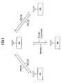
- FIG. 1 illustrates a conventional W-CDMA (Wideband-Code Division Multiple Access) based communication system.
- data is transmitted in a radio transmission channel called a DPDCH (Dedicated Physical Data CHannel).
- a base station controls uplink transmission power depending on reception quality of the DPDCHs for communication terminals.
- the reception quality may be represented by an indicator such as a SIR (Signal-to-Interference Ratio) and a bit error ratio.
- the base station uses a downlink transmission power control signal called a transmission power control (TPC) bit to control transmission power of the communication terminals within a relatively narrow range such as ⁇ 0.5-2 dB. See 3GPP TS25.214 V6.9.0 for this type of technique, for example.
- TPC transmission power control
- a communication terminal transmits data in a radio transmission channel called an E-DPDCH (Enhanced-Dedicated Physical Data Channel).
- E-DPDCH Enhanced-Dedicated Physical Data Channel
- a base station measures interference of the E-DPDCHs from the communication terminals and determines the allowable maximum of uplink transmission power for the individual communication terminals depending on the measured interference.
- the allowable maximum of uplink transmission power is derived from scheduling grants generated by the base station.
- the base station determines the scheduling grant for each of the communication terminals and transmits the scheduling grants to the communication terminals.
- the communication terminals may transmit uplink signals at the allowable maximum power designated in the scheduling grant or at a power level below the allowable maximum power. The communication terminals make the determination as to which power level is applied to the uplink transmissions.
- FIG. 2 schematically illustrates that the uplink transmission power varies over time.
- the uplink transmission power relatively slowly varies over time in the W-CDMA scheme.
- the uplink transmission power relatively drastically varies over time in the Enhanced Uplink scheme.
- the Enhanced Uplink scheme enables a communication terminal to determine the uplink transmission power flexibly. As a result, the uplink transmission power can be controlled more dynamically, resulting in effective utilization and power resources and throughput improvement. Instead, the communication terminal is required to support a wider dynamic range of the uplink transmission power than conventional schemes.
- a communication terminal presently communicating in a certain frequency migrates to a base station having a different frequency, the communication terminal must perform cell search for the different frequency.
- the communication terminal has only one frequency oscillator. For this reason, in the cell search for the different frequency, the communication terminal must stop the communications, switch to the different frequency for the cell search and switch back to the original frequency.
- a certain time period is predefined for the different frequency measurement in such a system environment so that the communication terminal can measure communication environments for the different frequency. This time period is called a transmission gap.
- a compressed mode the different frequency measurement occurs at a frequency while using the transmission gap. See 3GPP TS25.214 V6.9.0, for example.
- FIG. 3 schematically illustrates that the compressed mode is applied to the transmission power control as illustrated in FIG. 2 .
- the communication terminal switches the presently synchronized frequency to a different frequency within the transmission gap and accordingly does not transmit any data during the transmission gap.
- the uplink transmission power falls to zero in the transmission gap and significantly varies immediately after the start and the end of the transmission gap.
- the uplink transmission power may be lower in the W-CDMA scheme than in the Enhanced Uplink scheme.
- the W-CDMA scheme may cause less significant power variations immediately after the start and the end of the transmission gap.
- the communication terminal can relatively smoothly stop and restart transmissions.
- the Enhanced Uplink scheme may cause highly significant power variations immediately after the start and the end of the transmission gap, as illustrated in FIG. 4 , resulting in some problems in the stop and restart of transmissions.
- a power amplifier (RF amplifier) in the communication terminal cannot follow the drastic power variations, and distorted signals may be transmitted due to inappropriate power.
- a base station serving as a receiver of uplink signals also fails to follow the drastic power variations of the received signals, which may degrade reception quality such as causing increased bit errors or missing the received signals.
- One object of the present invention is to control the uplink transmission power appropriately near the transmission gap for different frequency measurement in the Enhanced Uplink scheme where a base station indicates allowable maximum uplink transmission power to a communication terminal.
- one aspect of the present invention relates to a communication terminal in an Enhanced Uplink based radio communication system, including:
- the uplink transmission power can be appropriately controlled near the transmission gap for different frequency measurement in the Enhanced Uplink scheme where a base station indicates allowable maximum uplink transmission power to a communication terminal.
- a transmission power control method for alleviating drastic variations of uplink transmission power is proposed for a radio communication system using the enhanced uplink scheme and the compressed mode scheme.
- the uplink transmission power is controlled to be lower than or equal to not only an allowable maximum power level as designated in a serving grant (SG) but also a further lower power level at start times and/or end times of transmission gap periods.
- the drastic power variations occurring at the start times and/or the end times of transmission gap periods can be reduced.
- a communication terminal computes the allowable maximum transmission power level depending on a schedule grant transmitted from a base station.
- the communication terminal transmits uplink signals at or below the allowable maximum power level. If the communication terminal transmits a large amount of information, the communication terminal transmits the uplink signals at the allowable maximum transmission power level for higher throughput. On the other hand, if the communication terminal transmits a small amount of information, the communication terminal transmits the uplink signals at a power level lower than the allowable maximum transmission power level to avoid radiating an excessive amount of radio waves in the environment and reduce interference within the cell.
- the communication terminal In the compressed mode, even if the communication terminal transmits a large amount of information, the communication terminal is forced to transmit the uplink signals at a power level lower than the allowable maximum transmission power level. Accordingly, it is possible to alleviate drastic variations of the transmission power due to stopping and restarting of transmissions around transmission gap periods. As a result, the transmission of uplink signals can be smoothly stopped and restarted, which can effectively prevent characteristic degradation due to signal distortions or transmission power distribution as experienced conventionally.
- FIG. 5 illustrates a radio communication system according to one embodiment of the present invention.
- the radio communication system may be an Enhanced Uplink based mobile communication system, for example.
- three communication terminals MSs communicate with each other via a base station BS.
- the present invention is not limited to the radio communication system including the three communication terminals and the single base station, and the radio communication system may include any number of communication terminals and base stations.
- the communication terminals may be user apparatuses such as mobile terminals but may be fixed terminals.
- FIG. 6 illustrates an overall operation flow (S601-S609) for use in the radio communication system in FIG. 5 according to one embodiment of the present invention.
- the communication terminals MSs transmit data in radio transmission channels called E-DPDCHs (Enhanced-Dedicated Physical Data Channels).
- E-DPDCHs Enhanced-Dedicated Physical Data Channels
- the base station BS measures interference of the E-DPDCHs transmitted from the communication terminals. Depending on the measured interference, the base station BS determines a schedule grant (SG) for each of the communication terminals and transmits the schedule grants to the communication terminals.
- the schedule grants SG may specify radio resources available for the respective communication terminals to transmit data channels.
- the base station BS transmits downlink control signals including the schedule grants SG to the communication terminals.
- the base stations use different frequencies. For this reason, when a communication terminal presently communicating with a base station at one of the frequencies is handed over to another base station having a different one of the frequencies, the communication terminal must perform cell search for the different frequency (different frequency measurement). If any of the communication terminals MSs needs to conduct the different frequency measurement, at step S604, the base station BS activates the compressed mode for that communication terminal MS.
- the base station BS informs the communication terminal MS of the activation of the compressed mode, a transmission gap (TG) or others in a downlink control signal.
- the communication terminal MS interrupts communications during the transmission gap, switches to a different frequency for cell search and then restores the original frequency.
- the communication terminal MS determines uplink transmission power based on the schedule grant SG received from the base station BS and the operating mode (whether the operating mode is set to the compressed mode). The determination of the uplink transmission power is described in detail below.
- the communication terminal transmits the uplink signals (E-DPDCHs) at the power level determined at step S606.
- the base station BS determines whether the communication terminal MS has to conduct the different frequency measurement any more, and if the communication terminal MS does not have to conduct the different frequency measurement any more, the base station BS deactivates the compressed mode.
- the base station BS transmits the deactivation of the compressed mode to the communication terminal MS.
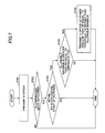
- FIG. 7 illustrates an exemplary detailed operation flow (S701-S705) of step S606 in FIG. 6 .
- step S701 corresponding to step S601 in FIG. 6 the communication terminal MS transmits data in an E-DPDCH.
- the communication terminal MS determines whether the compressed mode is activated. If the compressed mode is not activated, that is, if the operating mode is not set to the compressed mode, the communication terminal MS sets the uplink transmission power at or below the allowable maximum level derived from the schedule grant SG.
- the schedule grant SG may include an index for designating any of various allowable maximum levels.
- FIG. 8 illustrates exemplary correspondence between the indices and the allowable maximum levels.
- the base station BS and the mobile station MS store the correspondence in respective memories. For example, if the schedule grant SG transmitted from the base station BS includes index "30", the corresponding allowable maximum level of uplink transmission power for the communication terminal MS would be equal to (95/15) 2 ⁇ 4.
- the value "95 2 ⁇ 4" corresponds to power of data signals (square of amplitude), and the value "15 2 " corresponds to power of pilot signals (square of amplitude).
- the communication terminal MS is allowed to transmit uplink signals at or below the power level (95/15) 2 ⁇ 4. If the communication terminal MS has a large amount of information to be transmitted, the communication terminal MS can achieve faster throughput by transmitting the uplink signals at the allowable maximum level. On the other hand, if the communication terminal has a small amount of information to be transmitted, the communication terminal MS can inhibit excessive radiation of electric waves in the environment and reduce inner-cell interference by transmitting the uplink signals below the allowable maximum level. Based on such determination criteria, the communication terminal MS can determine the uplink transmission power. In other words, the communication terminal MS determines whether to increase or decrease the uplink transmission power by itself, which differs from the W-CDMA scheme where the base station BS instructs the communication terminal MS in TPC bits to increase or decrease the uplink transmission power.
- step S702 the flow proceeds to step S703.
- the communication terminal MS has already received information on the compressed mode from the base station BS (step S605 in FIG. 6 ). Particularly, at this time point, the communication terminal MS already has at least knowledge of when the transmission gap period is scheduled to arrive.
- the communication terminal MS determines whether the current time point is within a predefined period (e.g., six slots) immediately before the start of the transmission gap period TG.
- a predefined period e.g., six slots
- the schedule grant may be updated for each subframe of 2 ms, the subframe consisting of three slots. In this example, it is determined whether the current time point reaches two subframes before the transmission gap period.
- the above-mentioned specific values for the periods, subframes and slots are simply illustrative, and any other appropriate value may be applied.
- the uplink transmission power is determined similar to the case where the compressed mode is not activated. In other words, the uplink transmission power may be determined at or below the allowable maximum power level derived from the schedule grant SG.
- step S704 the allowable maximum power level derived from the schedule grant SG is compared to a predefined threshold.
- a predefined threshold As one example, it is assumed that the index corresponding to the threshold is equal to "13" in the correspondence table in FIG. 8 .
- the index corresponding to the allowable maximum power level is compared to the index corresponding to the threshold at step S704. Based on the comparison, if the index corresponding to the allowable maximum power level is less than the index corresponding to the threshold, the uplink transmission power is determined similar to the case of the compressed mode not being activated. Note that the magnitude relationship between the indices is equivalent to the magnitude relationship between the power levels.
- FIG. 9 illustrates the case where the allowable maximum transmission power level is less than the threshold at step S704 in FIG. 7 .
- the uplink transmission power may be set to or below the allowable maximum power level derived from the schedule grant SG.
- step S705 the uplink transmission power is bound to at most the threshold corresponding to index "13" independent of the allowable maximum power level derived from the schedule grant. For example, if the index corresponding to the allowable maximum power level is equal to "20", the uplink transmission power can be set to at most a power level corresponding to index "13" rather than one corresponding to index "20".
- FIG. 10 illustrates the case where the allowable maximum transmission power level is bound at step S705.
- the allowable maximum level is bound to threshold "13" within six slots immediately before the transmission gap period TG.
- the power level immediately after entering the transmission gap period can be bound to a lower power level corresponding to at most threshold "13".
- the allowable maximum transmission power level is bound to threshold "13" during the power restraint period consisting of two subframes equivalent to six slots) uniformly.
- the present invention is not limited to the embodiment. In other embodiments, the transmission power may be bound to different levels during the first subframe and the second subframe of the two subframes in the power restraint period.
- FIG. 11 illustrates the case where the transmission power is bound to first threshold "20" during the first subframe and second threshold "13" during the second subframe.
- the transmission power is bound to the two different thresholds. In other embodiments, however, the transmission power may be bound to three or more thresholds.
- the transmission power is bound at step S705 in FIG. 7 to the threshold used for comparison at step S704 but may be bound to any other value.
- the transmission power may be bound to an average value between the allowable maximum level derived from the schedule grant SG and the threshold used at step S704.
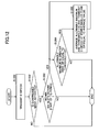
- FIG. 12 is a flowchart illustrating the case where the average value is applied. Although the flowchart is similar to the flowchart illustrated in FIG. 7 , at step S1205, an average value between the allowable maximum level derived from the schedule grant SG and threshold "13" used at step S1204 is calculated. The uplink transmission power is bound to or below the calculated average value.
- FIG. 13 illustrates another exemplary detailed operation flow (S1301-S1305) of step S606 in FIG. 6 . This flow is similar to that in FIG. 7 except step S1303.
- step S1301 the communication terminal MS transmits data in an E-DPDCH. This step corresponds to step S601 in FIG. 6 .
- the communication terminal MS determines whether the compressed mode is activated. If the compressed mode is not activated, that is, if the operating mode is not set to the compressed mode, the communication terminal MS sets the uplink transmission power at or below the allowable maximum level derived from the schedule grant SG.
- step S1303 the flow proceeds to step S1303.
- the communication terminal MS determines whether the current time point is within a predefined period (e.g., six slots) immediately after the end of the transmission gap period TG.
- a predefined period e.g., six slots
- the flow in FIG. 13 differs from that in FIG. 7 in that the determination is made for immediately after the end of the transmission gap period rather than for immediately before the start of the transmission gap period. If the current time point is not within six slots immediately after the end of the transmission gap period TG, the uplink transmission power is determined similar to the case where the compressed mode is not activated. In other words, the uplink transmission power may be determined at or below the allowable maximum power level derived from the schedule grant SG.
- step S1304 the allowable maximum power level derived from the schedule grant SG is compared to a predefined threshold. Based on the comparison, if the index corresponding to the allowable maximum power level is less than the index corresponding to the threshold, the uplink transmission power is determined similar to the case of the compressed mode not being activated.
- FIG. 14 illustrates the case where the allowable maximum transmission power level is higher than or equal to the threshold at step S1304.
- the uplink transmission power may be set to or below the allowable maximum level derived from the schedule grant SG.
- step S1305 the uplink transmission power is bound to at most the threshold, such as index "13", independent of the allowable maximum power level derived from the schedule grant. For example, if the index corresponding to the allowable maximum power level is equal to "20", the uplink transmission power can be set to at most a power level corresponding to index "13" rather than one corresponding to index "20".
- FIG. 15 illustrates the case where the allowable maximum transmission power level is bound at step S1305.
- the allowable maximum level is bound to threshold "13" within six slots immediately after end of the transmission gap period TG. In this manner, the power level immediately after exiting from the transmission gap period can be bound to a lower power level corresponding to at most threshold "13".
- the allowable maximum transmission power level is bound to threshold "13" during the power restraint period consisting of two subframes equivalent to six slots) uniformly.
- the present invention is not limited to the embodiment. In other embodiments, the transmission power may be bound to different levels during the first subframe and the second subframe of the two subframes in the power restraint period.
- FIG. 16 illustrates the case where the transmission power is bound to first threshold "13" during the first subframe and second threshold "20" during the second subframe.
- the transmission power is bound to the two different thresholds. In other embodiments, however, the transmission power may be bound to three or more thresholds.
- the transmission power is bound at step S1305 in FIG. 13 to the threshold used for comparison at step S1304 but may be bound to any other value.
- the transmission power may be bound to an average value between the allowable maximum level derived from the schedule grant SG and the threshold used at step S1304.
- FIG. 17 is a flowchart illustrating the case where the average value is applied. Although the flowchart is similar to the flowchart as illustrated in FIG. 13 , at step S1705, an average value between the allowable maximum level derived from the schedule grant SG and threshold "13" used at step S1704 is calculated. The uplink transmission power is bound to or below the calculated average value.
- FIG. 18 illustrates the case where the transmission power is bound both immediately before the start of the transmission gap period and immediately after the end of the transmission gap period.
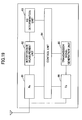
- FIG. 19 is a functional block diagram illustrating a base station BS.
- the base station BS includes a reception unit (Rx) 81, an interference measurement unit 82, a schedule grant (SG) determination unit 83, a control unit 84, a transmission signal generation unit 85 and a transmission unit (Tx) 86.
- Rx reception unit
- SG schedule grant
- Tx transmission unit
- the reception unit (Rx) 81 receives uplink signals from communication terminals. Particularly, the reception unit 81 receives data channels E-DPDCHs and decode and demodulates them.
- the interference measurement unit 82 measures reception quality of the data channel E-DPDCH.
- the reception quality may be represented as a SIR (Signal to Interference Ratio), a bit error rate, a S/N (Signal to Noise Ratio), a Ec/No or any other appropriate indicator.
- the reception quality may be represented as a reception power level, a field intensity level, a RSSI (Received Signal Strength Indicator) or any other appropriate indicator.
- the schedule grant determination unit 83 schedules radio resources based on an amount of interference from communication terminals.
- the schedule grant determination unit 83 particularly determines indices for specifying the allowable maximum uplink transmission power levels for different communication terminals.
- the control unit 84 controls operations of components in the base station BS.
- the transmission signal generation unit 85 generates downlink signals including one or more of downlink control signals, downlink data signals, pilot signals and other signals.
- the transmission unit (Tx) 86 converts digital signals generated by the transmission signal generation unit 85 into radio signals and transmits them.
- FIG. 20 is a functional block diagram illustrating a communication terminal.
- the communication terminal MS includes a reception unit (Rx) 91, a downlink control signal analysis unit 92, a control unit 93, a transmission signal generation unit 94 and a transmission unit (Tx) 95.
- Rx reception unit
- Tx transmission unit
- the reception unit (Rx) 91 receives downlink signals from base stations.
- the downlink signal includes one or more of downlink control signals, downlink data signals, pilot signals and other signals.
- the downlink control signal analysis unit 92 analyzes downlink control signals.
- the downlink control signal analysis unit 92 particularly extracts a schedule grant from the downlink control signals and assigns radio resources for downlink and/or uplink communications. If uplink transmission is enabled, the schedule grant includes an index for specifying the allowable maximum uplink transmission power. Also, in the compressed mode, the downlink control signal analysis unit 92 receives downlink control signals and/or pilot signals at different frequencies and performs different frequency measurement.
- the control unit 93 controls operations of components in the communication terminal MS.
- the transmission signal generation unit 94 generates uplink signals including one or more of uplink control signals, uplink data signals, pilot signals and other signals.
- the transmission unit (Tx) 95 converts digital signals generated by the transmission signal generation unit 94 into radio signals and transmits them. The transmission is carried out at the uplink transmission power determined by the control unit 93.
- FIG. 21 is a functional block diagram illustrating the control unit 93 in the communication terminal MS.
- the control unit 93 is coupled to the transmission unit 95 and an allowable maximum determination unit 21 and includes a compressed mode activation/deactivation determination unit 931, a threshold determination unit 932 and a transmission power control unit 933.
- the allowable maximum determination unit 21 belongs to the downlink control signal analysis unit 32 and uses a table as illustrated in FIG. 8 to determine an index designated in the schedule grant. In other embodiments, the allowable maximum determination unit 21 may be included in the control unit 93.
- the compressed mode activation/deactivation determination unit 931 determines whether the communication terminal MS is to operate in the compressed mode based on instructions from base stations.
- the threshold determination unit 932 compares the allowable maximum level with a threshold for magnitude and supplies the comparison.
- the transmission power control unit 933 determines the uplink transmission power based on the determination as to whether the current operating mode is the compressed mode and the threshold comparison. The determined uplink transmission power is reported to the transmission unit 95. The uplink transmission power is determined in accordance with the above-mentioned operation flow in FIGS. 7 and 13 .
- the present invention may be applied to any appropriate radio communication system where the Enhanced Uplink scheme and the compressed mode scheme are utilized.
- the present invention may be applied to a HSDPA/HSUPA based W-CDMA system, an LTE based system, an IMT-Advanced system, a WiMAX system, a Wi-Fi based system and others.
- the software may be embodied in a RAM (Random Access Memory), a flash memory, a ROM (Read Only Memory), a EPROM (Erasable Programmable ROM), a EEPROM (Electrically EPROM), a register, a hard disk drive (HDD), a removable disk, CD-ROM (Compact Disk-ROM) and any other appropriate storage medium.
- RAM Random Access Memory
- flash memory a ROM (Read Only Memory), a EPROM (Erasable Programmable ROM), a EEPROM (Electrically EPROM), a register, a hard disk drive (HDD), a removable disk, CD-ROM (Compact Disk-ROM) and any other appropriate storage medium.
Landscapes
- Engineering & Computer Science (AREA)
- Computer Networks & Wireless Communication (AREA)
- Signal Processing (AREA)
- Mobile Radio Communication Systems (AREA)
- Transceivers (AREA)
Abstract
Description
- The present invention relates to a communication terminal and a method for use in a radio communication system.
- Recent rapid popularization of the Internet, manifestation of pluralistic information, higher capacity and development of the next generation Internet have been promoting research and development of the next generation radio access schemes for implementing fast radio transmission in mobile communications. In such a fast radio environment, it is important to make not only downlink transmissions but also uplink transmissions faster. The 3rd Generation Partnership Project (3GPP) proposes an Enhanced Uplink scheme as an uplink speeding-up technique.
-
FIG. 1 illustrates a conventional W-CDMA (Wideband-Code Division Multiple Access) based communication system. In uplink communications in accordance with the W-CDMA scheme, data is transmitted in a radio transmission channel called a DPDCH (Dedicated Physical Data CHannel). A base station controls uplink transmission power depending on reception quality of the DPDCHs for communication terminals. For example, the reception quality may be represented by an indicator such as a SIR (Signal-to-Interference Ratio) and a bit error ratio. The base station uses a downlink transmission power control signal called a transmission power control (TPC) bit to control transmission power of the communication terminals within a relatively narrow range such as ±0.5-2 dB. See 3GPP TS25.214 V6.9.0 for this type of technique, for example. - On the other hand, in the Enhanced Uplink scheme, a communication terminal transmits data in a radio transmission channel called an E-DPDCH (Enhanced-Dedicated Physical Data Channel). A base station measures interference of the E-DPDCHs from the communication terminals and determines the allowable maximum of uplink transmission power for the individual communication terminals depending on the measured interference. The allowable maximum of uplink transmission power is derived from scheduling grants generated by the base station. The base station determines the scheduling grant for each of the communication terminals and transmits the scheduling grants to the communication terminals. The communication terminals may transmit uplink signals at the allowable maximum power designated in the scheduling grant or at a power level below the allowable maximum power. The communication terminals make the determination as to which power level is applied to the uplink transmissions. This differs from the W-CDMA based system in that the uplink transmission power is controlled through TPC bits transmitted to the communication terminals in accordance with the W-CDMA system. See 3GPP TS25.331 V6.9.0 for detailed calculation of the allowable maximum power level in the Enhance Uplink scheme, for example.
-
FIG. 2 schematically illustrates that the uplink transmission power varies over time. As illustrated, the uplink transmission power relatively slowly varies over time in the W-CDMA scheme. On the other hand, the uplink transmission power relatively drastically varies over time in the Enhanced Uplink scheme. The Enhanced Uplink scheme enables a communication terminal to determine the uplink transmission power flexibly. As a result, the uplink transmission power can be controlled more dynamically, resulting in effective utilization and power resources and throughput improvement. Instead, the communication terminal is required to support a wider dynamic range of the uplink transmission power than conventional schemes. - Meanwhile, there are some cases where base stations use different frequencies to accommodate a larger number of users. If a communication terminal presently communicating in a certain frequency migrates to a base station having a different frequency, the communication terminal must perform cell search for the different frequency. In general, the communication terminal has only one frequency oscillator. For this reason, in the cell search for the different frequency, the communication terminal must stop the communications, switch to the different frequency for the cell search and switch back to the original frequency. To this end, a certain time period is predefined for the different frequency measurement in such a system environment so that the communication terminal can measure communication environments for the different frequency. This time period is called a transmission gap. In an operating mode called a compressed mode, the different frequency measurement occurs at a frequency while using the transmission gap. See 3GPP TS25.214 V6.9.0, for example.
-
FIG. 3 schematically illustrates that the compressed mode is applied to the transmission power control as illustrated inFIG. 2 . The communication terminal switches the presently synchronized frequency to a different frequency within the transmission gap and accordingly does not transmit any data during the transmission gap. As a result, the uplink transmission power falls to zero in the transmission gap and significantly varies immediately after the start and the end of the transmission gap. - As stated above, the uplink transmission power may be lower in the W-CDMA scheme than in the Enhanced Uplink scheme. For this reason, the W-CDMA scheme may cause less significant power variations immediately after the start and the end of the transmission gap. Thus, the communication terminal can relatively smoothly stop and restart transmissions.
- On the other hand, the Enhanced Uplink scheme may cause highly significant power variations immediately after the start and the end of the transmission gap, as illustrated in
FIG. 4 , resulting in some problems in the stop and restart of transmissions. For example, a power amplifier (RF amplifier) in the communication terminal cannot follow the drastic power variations, and distorted signals may be transmitted due to inappropriate power. Also, a base station serving as a receiver of uplink signals also fails to follow the drastic power variations of the received signals, which may degrade reception quality such as causing increased bit errors or missing the received signals. - One object of the present invention is to control the uplink transmission power appropriately near the transmission gap for different frequency measurement in the Enhanced Uplink scheme where a base station indicates allowable maximum uplink transmission power to a communication terminal.
- In order to overcome the above-mentioned problems, one aspect of the present invention relates to a communication terminal in an Enhanced Uplink based radio communication system, including:
- a determination unit configured to analyze a received downlink control signal and determine an allowable maximum uplink transmission power level; a measurement unit configured to perform different frequency measurement in a transmission gap period;
- a threshold determination unit configured to determine whether the allowable maximum uplink transmission power level is higher than or equal to a threshold within a predefined period before a start of the transmission gap period and/or after an end of the transmission gap period; a transmission power control unit configured to set an uplink transmission power level; and a transmission unit configured to transmit an uplink signal at the uplink transmission power level determined by the uplink transmission power control unit, wherein if the allowable maximum uplink transmission power level is higher than or equal to the threshold, the transmission power control unit sets the uplink transmission power level to or below a predefined level lower than the allowable maximum uplink transmission power level within the predefined period before the start of the transmission gap period and/or after the end of the transmission gap period.
- According to the aspect of the present invention, the uplink transmission power can be appropriately controlled near the transmission gap for different frequency measurement in the Enhanced Uplink scheme where a base station indicates allowable maximum uplink transmission power to a communication terminal.
- Other objects, features and advantages of the present invention will become more apparent from the following detailed description when read in conjunction with the accompanying drawings, in which:
-
FIG. 1 illustrates a W-CDMA based communication system; -
FIG. 2 schematically illustrates that uplink transmission power varies over time; -
FIG. 3 schematically illustrates that a compressed mode is applied; -
FIG. 4 illustrates that there are drastic power variations near transmission gaps; -
FIG. 5 illustrates an exemplary communication system according to one embodiment of the present invention; -
FIG. 6 is a flowchart of an overall operation according to one embodiment of the present invention; -
FIG. 7 is a flowchart of an exemplary detailed operation of step S6 inFIG. 6 ; -
FIG. 8 illustrates an exemplary correspondence table between indices and allowable maximum power levels; -
FIG. 9 illustrates an exemplary case where the allowable maximum power level does not exceed a threshold; -
FIG. 10 illustrates an exemplary case where the allowable maximum power level exceeds the threshold; -
FIG. 11 illustrates that the transmission power is controlled in two steps; -
FIG. 12 illustrates an exemplary variation of the operation illustrated inFIG. 7 ; -
FIG. 13 is a flowchart of another detailed operation of step S6 inFIG. 6 ; -
FIG. 14 illustrates an exemplary case where the allowable maximum power level does not exceed a threshold; -
FIG. 15 illustrates an exemplary case where the allowable maximum power level exceeds the threshold; -
FIG. 16 illustrates that the transmission power is controlled in two steps; -
FIG. 17 illustrates an exemplary variation of the operation illustrated inFIG. 13 ; -
FIG. 18 illustrates that the transmission power is controlled immediately before the start of transmission gaps as well as immediately after the end of the transmission gaps; -
FIG. 19 is a functional block diagram illustrating a base station according to one embodiment of the present invention; -
FIG. 20 is a functional block diagram illustrating a communication terminal; and -
FIG. 21 is a functional block diagram illustrating a control unit in the communication terminal. - Preferred embodiments of the present invention will be described in detail below with reference to the accompanying drawings.
- In one embodiment of the present invention, a transmission power control method for alleviating drastic variations of uplink transmission power is proposed for a radio communication system using the enhanced uplink scheme and the compressed mode scheme. Specifically, the uplink transmission power is controlled to be lower than or equal to not only an allowable maximum power level as designated in a serving grant (SG) but also a further lower power level at start times and/or end times of transmission gap periods. According to this embodiment, the drastic power variations occurring at the start times and/or the end times of transmission gap periods can be reduced.
- In one embodiment of the present invention, a communication terminal computes the allowable maximum transmission power level depending on a schedule grant transmitted from a base station. The communication terminal transmits uplink signals at or below the allowable maximum power level. If the communication terminal transmits a large amount of information, the communication terminal transmits the uplink signals at the allowable maximum transmission power level for higher throughput. On the other hand, if the communication terminal transmits a small amount of information, the communication terminal transmits the uplink signals at a power level lower than the allowable maximum transmission power level to avoid radiating an excessive amount of radio waves in the environment and reduce interference within the cell. In the compressed mode, even if the communication terminal transmits a large amount of information, the communication terminal is forced to transmit the uplink signals at a power level lower than the allowable maximum transmission power level. Accordingly, it is possible to alleviate drastic variations of the transmission power due to stopping and restarting of transmissions around transmission gap periods. As a result, the transmission of uplink signals can be smoothly stopped and restarted, which can effectively prevent characteristic degradation due to signal distortions or transmission power distribution as experienced conventionally.
-
FIG. 5 illustrates a radio communication system according to one embodiment of the present invention. The radio communication system may be an Enhanced Uplink based mobile communication system, for example. InFIG. 5 , three communication terminals MSs communicate with each other via a base station BS. However, the present invention is not limited to the radio communication system including the three communication terminals and the single base station, and the radio communication system may include any number of communication terminals and base stations. Typically, the communication terminals may be user apparatuses such as mobile terminals but may be fixed terminals. -
FIG. 6 illustrates an overall operation flow (S601-S609) for use in the radio communication system inFIG. 5 according to one embodiment of the present invention. - At step S601, the communication terminals MSs transmit data in radio transmission channels called E-DPDCHs (Enhanced-Dedicated Physical Data Channels).
- At step S602, the base station BS measures interference of the E-DPDCHs transmitted from the communication terminals. Depending on the measured interference, the base station BS determines a schedule grant (SG) for each of the communication terminals and transmits the schedule grants to the communication terminals. As is known to those skilled in the art, the schedule grants SG may specify radio resources available for the respective communication terminals to transmit data channels.
- At step S603, the base station BS transmits downlink control signals including the schedule grants SG to the communication terminals.
- In this embodiment, the base stations use different frequencies. For this reason, when a communication terminal presently communicating with a base station at one of the frequencies is handed over to another base station having a different one of the frequencies, the communication terminal must perform cell search for the different frequency (different frequency measurement). If any of the communication terminals MSs needs to conduct the different frequency measurement, at step S604, the base station BS activates the compressed mode for that communication terminal MS.
- At step S605, the base station BS informs the communication terminal MS of the activation of the compressed mode, a transmission gap (TG) or others in a downlink control signal. In the compressed mode, the communication terminal MS interrupts communications during the transmission gap, switches to a different frequency for cell search and then restores the original frequency.
- At step S606, in order to transmit uplink signals, the communication terminal MS determines uplink transmission power based on the schedule grant SG received from the base station BS and the operating mode (whether the operating mode is set to the compressed mode). The determination of the uplink transmission power is described in detail below.
- At step S607, the communication terminal transmits the uplink signals (E-DPDCHs) at the power level determined at step S606.
- At step S608, the base station BS determines whether the communication terminal MS has to conduct the different frequency measurement any more, and if the communication terminal MS does not have to conduct the different frequency measurement any more, the base station BS deactivates the compressed mode.
- At step S609, the base station BS transmits the deactivation of the compressed mode to the communication terminal MS.
-
FIG. 7 illustrates an exemplary detailed operation flow (S701-S705) of step S606 inFIG. 6 . - At step S701 corresponding to step S601 in
FIG. 6 , the communication terminal MS transmits data in an E-DPDCH. - At step S702, the communication terminal MS determines whether the compressed mode is activated. If the compressed mode is not activated, that is, if the operating mode is not set to the compressed mode, the communication terminal MS sets the uplink transmission power at or below the allowable maximum level derived from the schedule grant SG. The schedule grant SG may include an index for designating any of various allowable maximum levels.
-
FIG. 8 illustrates exemplary correspondence between the indices and the allowable maximum levels. The base station BS and the mobile station MS store the correspondence in respective memories. For example, if the schedule grant SG transmitted from the base station BS includes index "30", the corresponding allowable maximum level of uplink transmission power for the communication terminal MS would be equal to (95/15)2×4. The value "952×4" corresponds to power of data signals (square of amplitude), and the value "152" corresponds to power of pilot signals (square of amplitude). - According to this schedule grant SG, the communication terminal MS is allowed to transmit uplink signals at or below the power level (95/15)2 ×4. If the communication terminal MS has a large amount of information to be transmitted, the communication terminal MS can achieve faster throughput by transmitting the uplink signals at the allowable maximum level. On the other hand, if the communication terminal has a small amount of information to be transmitted, the communication terminal MS can inhibit excessive radiation of electric waves in the environment and reduce inner-cell interference by transmitting the uplink signals below the allowable maximum level. Based on such determination criteria, the communication terminal MS can determine the uplink transmission power. In other words, the communication terminal MS determines whether to increase or decrease the uplink transmission power by itself, which differs from the W-CDMA scheme where the base station BS instructs the communication terminal MS in TPC bits to increase or decrease the uplink transmission power.
- On the other hand, if it is determined that the operating mode is set to the compressed mode at step S702 in
FIG. 7 , the flow proceeds to step S703. In this case, the communication terminal MS has already received information on the compressed mode from the base station BS (step S605 inFIG. 6 ). Particularly, at this time point, the communication terminal MS already has at least knowledge of when the transmission gap period is scheduled to arrive. - At step S703, the communication terminal MS determines whether the current time point is within a predefined period (e.g., six slots) immediately before the start of the transmission gap period TG. As one example, the schedule grant may be updated for each subframe of 2 ms, the subframe consisting of three slots. In this example, it is determined whether the current time point reaches two subframes before the transmission gap period. However, the above-mentioned specific values for the periods, subframes and slots are simply illustrative, and any other appropriate value may be applied.
- If the current time point is not within six slots immediately before the start of the transmission gap period TG, the uplink transmission power is determined similar to the case where the compressed mode is not activated. In other words, the uplink transmission power may be determined at or below the allowable maximum power level derived from the schedule grant SG.
- On the other hand, if the current time point is within six slots immediately before the start of the transmission gap period TG, the flow proceeds to step S704. At step S704, the allowable maximum power level derived from the schedule grant SG is compared to a predefined threshold. As one example, it is assumed that the index corresponding to the threshold is equal to "13" in the correspondence table in
FIG. 8 . Specifically, the index corresponding to the allowable maximum power level is compared to the index corresponding to the threshold at step S704. Based on the comparison, if the index corresponding to the allowable maximum power level is less than the index corresponding to the threshold, the uplink transmission power is determined similar to the case of the compressed mode not being activated. Note that the magnitude relationship between the indices is equivalent to the magnitude relationship between the power levels. -
FIG. 9 illustrates the case where the allowable maximum transmission power level is less than the threshold at step S704 inFIG. 7 . In this case, the uplink transmission power may be set to or below the allowable maximum power level derived from the schedule grant SG. - Based on the comparison at step S704 in
FIG. 7 , if the allowable maximum power level is higher than or equal to the threshold, the flow proceeds to step S705. At step S705, the uplink transmission power is bound to at most the threshold corresponding to index "13" independent of the allowable maximum power level derived from the schedule grant. For example, if the index corresponding to the allowable maximum power level is equal to "20", the uplink transmission power can be set to at most a power level corresponding to index "13" rather than one corresponding to index "20". -
FIG. 10 illustrates the case where the allowable maximum transmission power level is bound at step S705. In this case, the allowable maximum level is bound to threshold "13" within six slots immediately before the transmission gap period TG.
In this manner, the power level immediately after entering the transmission gap period can be bound to a lower power level corresponding to at most threshold "13". - In the embodiment illustrated in
FIG. 10 , the allowable maximum transmission power level is bound to threshold "13" during the power restraint period consisting of two subframes equivalent to six slots) uniformly. However, the present invention is not limited to the embodiment. In other embodiments, the transmission power may be bound to different levels during the first subframe and the second subframe of the two subframes in the power restraint period. -
FIG. 11 illustrates the case where the transmission power is bound to first threshold "20" during the first subframe and second threshold "13" during the second subframe. In this embodiment, the transmission power is bound to the two different thresholds. In other embodiments, however, the transmission power may be bound to three or more thresholds. - The transmission power is bound at step S705 in
FIG. 7 to the threshold used for comparison at step S704 but may be bound to any other value. For example, the transmission power may be bound to an average value between the allowable maximum level derived from the schedule grant SG and the threshold used at step S704. -
FIG. 12 is a flowchart illustrating the case where the average value is applied. Although the flowchart is similar to the flowchart illustrated inFIG. 7 , at step S1205, an average value between the allowable maximum level derived from the schedule grant SG and threshold "13" used at step S1204 is calculated. The uplink transmission power is bound to or below the calculated average value. -
FIG. 13 illustrates another exemplary detailed operation flow (S1301-S1305) of step S606 inFIG. 6 . This flow is similar to that inFIG. 7 except step S1303. - At step S1301, the communication terminal MS transmits data in an E-DPDCH. This step corresponds to step S601 in
FIG. 6 . - At step S1302, the communication terminal MS determines whether the compressed mode is activated. If the compressed mode is not activated, that is, if the operating mode is not set to the compressed mode, the communication terminal MS sets the uplink transmission power at or below the allowable maximum level derived from the schedule grant SG.
- On the other hand, if the operating mode is set to the compressed mode at step S1302, the flow proceeds to step S1303.
- At step S1303, the communication terminal MS determines whether the current time point is within a predefined period (e.g., six slots) immediately after the end of the transmission gap period TG. The flow in
FIG. 13 differs from that inFIG. 7 in that the determination is made for immediately after the end of the transmission gap period rather than for immediately before the start of the transmission gap period. If the current time point is not within six slots immediately after the end of the transmission gap period TG, the uplink transmission power is determined similar to the case where the compressed mode is not activated. In other words, the uplink transmission power may be determined at or below the allowable maximum power level derived from the schedule grant SG. - On the other hand, if the current time point is within six slots immediately after the end of the transmission gap period TG, the flow proceeds to step S1304. At step S1304, the allowable maximum power level derived from the schedule grant SG is compared to a predefined threshold. Based on the comparison, if the index corresponding to the allowable maximum power level is less than the index corresponding to the threshold, the uplink transmission power is determined similar to the case of the compressed mode not being activated.
-
FIG. 14 illustrates the case where the allowable maximum transmission power level is higher than or equal to the threshold at step S1304. In this case, the uplink transmission power may be set to or below the allowable maximum level derived from the schedule grant SG. - If the allowable maximum transmission power level is higher than or equal to the threshold based on the comparison at step S1304 in
FIG. 13 , the flow proceeds to step S1305. At step S1305, the uplink transmission power is bound to at most the threshold, such as index "13", independent of the allowable maximum power level derived from the schedule grant. For example, if the index corresponding to the allowable maximum power level is equal to "20", the uplink transmission power can be set to at most a power level corresponding to index "13" rather than one corresponding to index "20". -
FIG. 15 illustrates the case where the allowable maximum transmission power level is bound at step S1305. In this case, the allowable maximum level is bound to threshold "13" within six slots immediately after end of the transmission gap period TG. In this manner, the power level immediately after exiting from the transmission gap period can be bound to a lower power level corresponding to at most threshold "13". - In the embodiment illustrated in
FIG. 15 , the allowable maximum transmission power level is bound to threshold "13" during the power restraint period consisting of two subframes equivalent to six slots) uniformly. However, the present invention is not limited to the embodiment. In other embodiments, the transmission power may be bound to different levels during the first subframe and the second subframe of the two subframes in the power restraint period. -
FIG. 16 illustrates the case where the transmission power is bound to first threshold "13" during the first subframe and second threshold "20" during the second subframe. In this embodiment, the transmission power is bound to the two different thresholds. In other embodiments, however, the transmission power may be bound to three or more thresholds. - The transmission power is bound at step S1305 in
FIG. 13 to the threshold used for comparison at step S1304 but may be bound to any other value. For example, the transmission power may be bound to an average value between the allowable maximum level derived from the schedule grant SG and the threshold used at step S1304. -
FIG. 17 is a flowchart illustrating the case where the average value is applied. Although the flowchart is similar to the flowchart as illustrated inFIG. 13 , at step S1705, an average value between the allowable maximum level derived from the schedule grant SG and threshold "13" used at step S1704 is calculated. The uplink transmission power is bound to or below the calculated average value. - In this embodiment, either or both of the flowcharts in
FIGS. 7 and13 may be applied. -
FIG. 18 illustrates the case where the transmission power is bound both immediately before the start of the transmission gap period and immediately after the end of the transmission gap period. -
FIG. 19 is a functional block diagram illustrating a base station BS. InFIG. 19 , the base station BS includes a reception unit (Rx) 81, aninterference measurement unit 82, a schedule grant (SG)determination unit 83, acontrol unit 84, a transmissionsignal generation unit 85 and a transmission unit (Tx) 86. - The reception unit (Rx) 81 receives uplink signals from communication terminals. Particularly, the
reception unit 81 receives data channels E-DPDCHs and decode and demodulates them. - The
interference measurement unit 82 measures reception quality of the data channel E-DPDCH. The reception quality may be represented as a SIR (Signal to Interference Ratio), a bit error rate, a S/N (Signal to Noise Ratio), a Ec/No or any other appropriate indicator. Alternatively, the reception quality may be represented as a reception power level, a field intensity level, a RSSI (Received Signal Strength Indicator) or any other appropriate indicator. - The schedule
grant determination unit 83 schedules radio resources based on an amount of interference from communication terminals. In this embodiment, the schedulegrant determination unit 83 particularly determines indices for specifying the allowable maximum uplink transmission power levels for different communication terminals. - The
control unit 84 controls operations of components in the base station BS. - The transmission
signal generation unit 85 generates downlink signals including one or more of downlink control signals, downlink data signals, pilot signals and other signals. - The transmission unit (Tx) 86 converts digital signals generated by the transmission
signal generation unit 85 into radio signals and transmits them. -
FIG. 20 is a functional block diagram illustrating a communication terminal. InFIG. 20 the communication terminal MS includes a reception unit (Rx) 91, a downlink controlsignal analysis unit 92, acontrol unit 93, a transmissionsignal generation unit 94 and a transmission unit (Tx) 95. - The reception unit (Rx) 91 receives downlink signals from base stations. As stated above, the downlink signal includes one or more of downlink control signals, downlink data signals, pilot signals and other signals.
- The downlink control
signal analysis unit 92 analyzes downlink control signals. In this embodiment, the downlink controlsignal analysis unit 92 particularly extracts a schedule grant from the downlink control signals and assigns radio resources for downlink and/or uplink communications. If uplink transmission is enabled, the schedule grant includes an index for specifying the allowable maximum uplink transmission power. Also, in the compressed mode, the downlink controlsignal analysis unit 92 receives downlink control signals and/or pilot signals at different frequencies and performs different frequency measurement. - The
control unit 93 controls operations of components in the communication terminal MS. - The transmission
signal generation unit 94 generates uplink signals including one or more of uplink control signals, uplink data signals, pilot signals and other signals. - The transmission unit (Tx) 95 converts digital signals generated by the transmission
signal generation unit 94 into radio signals and transmits them. The transmission is carried out at the uplink transmission power determined by thecontrol unit 93. -
FIG. 21 is a functional block diagram illustrating thecontrol unit 93 in the communication terminal MS. InFIG. 21 , thecontrol unit 93 is coupled to thetransmission unit 95 and an allowablemaximum determination unit 21 and includes a compressed mode activation/deactivation determination unit 931, athreshold determination unit 932 and a transmissionpower control unit 933. - The allowable
maximum determination unit 21 belongs to the downlink controlsignal analysis unit 32 and uses a table as illustrated inFIG. 8 to determine an index designated in the schedule grant. In other embodiments, the allowablemaximum determination unit 21 may be included in thecontrol unit 93. - The compressed mode activation/
deactivation determination unit 931 determines whether the communication terminal MS is to operate in the compressed mode based on instructions from base stations. - The
threshold determination unit 932 compares the allowable maximum level with a threshold for magnitude and supplies the comparison. - The transmission
power control unit 933 determines the uplink transmission power based on the determination as to whether the current operating mode is the compressed mode and the threshold comparison. The determined uplink transmission power is reported to thetransmission unit 95. The uplink transmission power is determined in accordance with the above-mentioned operation flow inFIGS. 7 and13 . - The present invention may be applied to any appropriate radio communication system where the Enhanced Uplink scheme and the compressed mode scheme are utilized. For example, the present invention may be applied to a HSDPA/HSUPA based W-CDMA system, an LTE based system, an IMT-Advanced system, a WiMAX system, a Wi-Fi based system and others.
- The present invention has been described with reference to the specific embodiments, but the embodiments are simply illustrative and variations, modifications, alterations and substitutions could be contrived by those skilled in the art. In the above description, some specific numerical values are used for better understanding of the present invention Unless specifically indicated, however, these numerical values are simply illustrative and any other suitable values may be used. For convenience, apparatuses according to the embodiments of the present invention have been described with reference to functional block diagrams, but these apparatuses may be implemented in hardware, software or combinations thereof. The software may be embodied in a RAM (Random Access Memory), a flash memory, a ROM (Read Only Memory), a EPROM (Erasable Programmable ROM), a EEPROM (Electrically EPROM), a register, a hard disk drive (HDD), a removable disk, CD-ROM (Compact Disk-ROM) and any other appropriate storage medium. The present invention is not limited to the above embodiments, and variations, modifications, alterations and substitutions can be made by those skilled in the art without deviating from the spirit of the present invention.
- The present application is based on Japanese Priority Application No.
2009-103133 filed on April 21, 2009
Claims (5)
- A communication terminal in an Enhanced Uplink based radio communication system, comprising:a determination unit configured to analyze a received downlink control signal and determine an allowable maximum uplink transmission power level;a measurement unit configured to perform different frequency measurement in a transmission gap period;a threshold determination unit configured to determine whether the allowable maximum uplink transmission power level is higher than or equal to a threshold within a predefined period before a start of the transmission gap period and/or after an end of the transmission gap period;a transmission power control unit configured to set an uplink transmission power level; anda transmission unit configured to transmit an uplink signal at the uplink transmission power level determined by the uplink transmission power control unit, whereinif the allowable maximum uplink transmission power level is higher than or equal to the threshold, the transmission power control unit sets the uplink transmission power level to or below a predefined level lower than the allowable maximum uplink transmission power level within the predefined period before the start of the transmission gap period and/or after the end of the transmission gap period.
- The communication terminal as claimed in claim 1, wherein the transmission unit transmits a portion of the uplink signal at a first uplink transmission power level lower than the allowable maximum uplink transmission power level and the other portion of the uplink signal at a second uplink transmission power level lower than the allowable maximum uplink transmission power level within the predefined period before the start of the transmission gap period and/or after the end of the transmission gap period.
- The communication terminal as claimed in claim 2, wherein the first or second transmission power level corresponds to an average power level between the allowable maximum uplink transmission power level and the threshold.
- A method for use in a communication terminal in an Enhanced Uplink based radio communication system wherein the communication terminal includes a determination unit configured to analyze a received downlink control signal and determine an allowable maximum uplink transmission power level and a measurement unit configured to perform different frequency measurement in a transmission gap period, the method comprising:determining whether the allowable maximum uplink transmission power level is higher than or equal to a threshold within a predefined period before a start of the transmission gap period and/or after an end of the transmission gap period;setting an uplink transmission power level; andtransmitting an uplink signal at the uplink transmission power level determined at the setting step, whereinif the allowable maximum uplink transmission power level is higher than or equal to the threshold, the step of setting comprises setting the uplink transmission power level to or below a predefined level lower than the allowable maximum uplink transmission power level within the predefined period before the start of the transmission gap period and/or after the end of the transmission gap period.
- An Enhanced Uplink based radio communication system, comprising:a communication terminal; anda base station configured to measure interference of an uplink signal for the communication terminal, determine an allowable maximum uplink transmission power level for the communication terminal based on the interference and transmit a downlink control signal indicative of the allowable maximum uplink transmission power level, whereinthe communication terminal includes a determination unit configured to analyze the received downlink control signal and determine the allowable maximum uplink transmission power level; a measurement unit configured to perform different frequency measurement in a transmission gap period; a threshold determination unit configured to determine whether the allowable maximum uplink transmission power level is higher than or equal to a threshold within a predefined period before a start of the transmission gap period and/or after an end of the transmission gap period; a transmission power control unit configured to set an uplink transmission power level; and a transmission unit configured to transmit an uplink signal at the uplink transmission power level determined by the uplink transmission power control unit, andif the allowable maximum uplink transmission power level is higher than or equal to the threshold, the transmission power control unit sets the uplink transmission power level to or below a predefined level lower than the allowable maximum uplink transmission power level within the predefined period before the start of the transmission gap period and/or after the end of the transmission gap period.
Applications Claiming Priority (1)
| Application Number | Priority Date | Filing Date | Title |
|---|---|---|---|
| JP2009103133A JP4787890B2 (en) | 2009-04-21 | 2009-04-21 | Communication terminal and method used in wireless communication system |
Publications (3)
| Publication Number | Publication Date |
|---|---|
| EP2244511A2 true EP2244511A2 (en) | 2010-10-27 |
| EP2244511A3 EP2244511A3 (en) | 2011-05-25 |
| EP2244511B1 EP2244511B1 (en) | 2013-09-11 |
Family
ID=42342615
Family Applications (1)
| Application Number | Title | Priority Date | Filing Date |
|---|---|---|---|
| EP20100250783 Not-in-force EP2244511B1 (en) | 2009-04-21 | 2010-04-15 | Communication terminal and method for use in radio communication system |
Country Status (4)
| Country | Link |
|---|---|
| US (1) | US8295873B2 (en) |
| EP (1) | EP2244511B1 (en) |
| JP (1) | JP4787890B2 (en) |
| CN (1) | CN101873684B (en) |
Families Citing this family (7)
| Publication number | Priority date | Publication date | Assignee | Title |
|---|---|---|---|---|
| JP4792513B2 (en) * | 2009-04-27 | 2011-10-12 | 株式会社エヌ・ティ・ティ・ドコモ | Method and communication terminal used in radio communication system |
| WO2012012836A1 (en) * | 2010-07-28 | 2012-02-02 | Cohda Wireless Pty Ltd | An intelligent transportation systems device |
| WO2012057094A1 (en) | 2010-10-25 | 2012-05-03 | Yamamoto Kazuhiro | Communication device |
| WO2013164895A1 (en) * | 2012-05-02 | 2013-11-07 | Yamamoto Kazuhiro | Wireless base station |
| AR108438A1 (en) * | 2016-05-13 | 2018-08-22 | Ericsson Telefon Ab L M | UPPER LINK POWER CONTROL FOR SOUND REFERENCE SIGNAL CARRIER-BASED SWITCHING |
| CN112243272B (en) * | 2019-07-16 | 2022-12-16 | 中国移动通信集团浙江有限公司 | Pilot frequency switching method and device |
| WO2021088052A1 (en) * | 2019-11-08 | 2021-05-14 | Oppo广东移动通信有限公司 | Method and device for information processing, storage medium, and chip |
Family Cites Families (19)
| Publication number | Priority date | Publication date | Assignee | Title |
|---|---|---|---|---|
| DE69936806T2 (en) * | 1998-03-26 | 2008-04-30 | Mitsubishi Denki K.K. | Spreizspektrumnachrichtenübertragungsverfahren |
| KR100433910B1 (en) * | 1999-02-13 | 2004-06-04 | 삼성전자주식회사 | apparatus and method for controlling power for inter-frequency handoff in cdma communication system |
| KR100487245B1 (en) * | 2001-11-28 | 2005-05-03 | 삼성전자주식회사 | Apparatus for minimizing transmission impossibility time due to compressed mode in mobile communication system using high speed downlink packet access scheme and method thereof |
| CA2431847A1 (en) * | 2003-06-09 | 2004-12-09 | Mantha Ramesh | System and method for managing available uplink transmit power |
| JP4409991B2 (en) * | 2004-03-01 | 2010-02-03 | 富士通株式会社 | Transmission control system using link aggregation |
| CN1734967A (en) * | 2004-08-10 | 2006-02-15 | 北京三星通信技术研究有限公司 | The outer-loop power controlling method of ascending reinforced special channel |
| JP4737553B2 (en) * | 2004-10-20 | 2011-08-03 | 日本電気株式会社 | Wireless communication system, mobile station, base station, wireless communication system control method used therefor, and program thereof |
| GB2420250B (en) * | 2004-11-12 | 2007-09-19 | Siemens Ag | A method of controlling interference from a terminal at a base station |
| US7724656B2 (en) * | 2005-01-14 | 2010-05-25 | Telefonaktiebolaget Lm Ericsson (Publ) | Uplink congestion detection and control between nodes in a radio access network |
| JP4651462B2 (en) * | 2005-06-17 | 2011-03-16 | 株式会社エヌ・ティ・ティ・ドコモ | Channel transmission apparatus and channel transmission method |
| WO2007029066A2 (en) * | 2005-08-05 | 2007-03-15 | Nokia Corporation | Power control for discontinuous uplink control channels |
| JP2007150860A (en) * | 2005-11-29 | 2007-06-14 | Matsushita Electric Ind Co Ltd | Control station apparatus and wireless communication method |
| JP4745153B2 (en) * | 2006-06-30 | 2011-08-10 | 富士通株式会社 | Transmission power control apparatus and transmission power control method |
| WO2008066428A1 (en) * | 2006-11-28 | 2008-06-05 | Telefonaktiebolaget Lm Ericsson (Publ) | A method and a system for down link control in a cellular telephony system |
| US8755270B2 (en) * | 2007-02-05 | 2014-06-17 | Telefonaktiebolaget L M Ericsson (Publ) | Congestion/load indication for high speed packet access |
| JP4907472B2 (en) * | 2007-09-05 | 2012-03-28 | 株式会社エヌ・ティ・ティ・ドコモ | Radio base station and physical control channel receiving method |
| JP5171196B2 (en) * | 2007-10-09 | 2013-03-27 | 株式会社エヌ・ティ・ティ・ドコモ | Wireless communication system, wireless communication method, and base station |
| US8396503B2 (en) * | 2007-10-19 | 2013-03-12 | Telefonaktiebolaget L M Ericsson (Publ) | Updating a signal quality target for uplink power control in a radio communication system responsive to estimated required signal quality for changing transmission formats |
| US8611943B2 (en) * | 2007-11-09 | 2013-12-17 | Telefonaktiebolaget L M Ericsson (Publ) | Power control in a radio communication system with multiple transport formats |
-
2009
- 2009-04-21 JP JP2009103133A patent/JP4787890B2/en not_active Expired - Fee Related
-
2010
- 2010-04-15 EP EP20100250783 patent/EP2244511B1/en not_active Not-in-force
- 2010-04-15 US US12/760,918 patent/US8295873B2/en not_active Expired - Fee Related
- 2010-04-20 CN CN2010101658640A patent/CN101873684B/en not_active Expired - Fee Related
Non-Patent Citations (1)
| Title |
|---|
| None |
Also Published As
| Publication number | Publication date |
|---|---|
| CN101873684B (en) | 2013-07-17 |
| JP2010258524A (en) | 2010-11-11 |
| JP4787890B2 (en) | 2011-10-05 |
| US20100267413A1 (en) | 2010-10-21 |
| EP2244511A3 (en) | 2011-05-25 |
| EP2244511B1 (en) | 2013-09-11 |
| CN101873684A (en) | 2010-10-27 |
| US8295873B2 (en) | 2012-10-23 |
Similar Documents
| Publication | Publication Date | Title |
|---|---|---|
| EP1142408B1 (en) | System and method for estimating interfrequency measurements used for radio network function | |
| KR100765892B1 (en) | Method for Controlling Intercell Interference in Mobile Communication System | |
| EP2244511B1 (en) | Communication terminal and method for use in radio communication system | |
| JP4859678B2 (en) | Cell selection method, user terminal and cell selection device | |
| EP3132643B1 (en) | Channel selection scanning in shared spectrum | |
| EP2092662B1 (en) | Inter-cell power control for interference management | |
| US8520640B2 (en) | Frequency quality criteria for inter-frequency handover in a TD-CDMA communication system | |
| US20180167897A1 (en) | Reporting power limit and corresponding constraint | |
| KR100928613B1 (en) | Method, apparatus and base station for determining radio link characteristics | |
| UA83729C2 (en) | Control for multi-antenna receive diversity in a wireless communication system | |
| US20080287127A1 (en) | Forward access channel measurement occasion scheduling device | |
| EP3047591A1 (en) | Inter-cell coordination in cellular deployment | |
| US9161388B2 (en) | Radio base station and methods thereof | |
| US9723570B2 (en) | Power control method and apparatus | |
| US20130223266A1 (en) | Mobile communications system, base station, and transmit power control method | |
| EP1576742B1 (en) | Method and apparatus for determining a transmit power | |
| KR20170018059A (en) | Transmission power control command word generation method, device and system | |
| JP2004260446A (en) | Mobile communication system, radio control apparatus, base station, and transmission power control method | |
| EP2946616A1 (en) | Method and device of performing multi-radio access bearer power scaling |
Legal Events
| Date | Code | Title | Description |
|---|---|---|---|
| PUAI | Public reference made under article 153(3) epc to a published international application that has entered the european phase |
Free format text: ORIGINAL CODE: 0009012 |
|
| 17P | Request for examination filed |
Effective date: 20100421 |
|
| AK | Designated contracting states |
Kind code of ref document: A2 Designated state(s): AT BE BG CH CY CZ DE DK EE ES FI FR GB GR HR HU IE IS IT LI LT LU LV MC MK MT NL NO PL PT RO SE SI SK SM TR |
|
| AX | Request for extension of the european patent |
Extension state: AL BA ME RS |
|
| RIN1 | Information on inventor provided before grant (corrected) |
Inventor name: MAEDA, MASATO Inventor name: IIZUKA, YOUSUKE |
|
| PUAL | Search report despatched |
Free format text: ORIGINAL CODE: 0009013 |
|
| AK | Designated contracting states |
Kind code of ref document: A3 Designated state(s): AT BE BG CH CY CZ DE DK EE ES FI FR GB GR HR HU IE IS IT LI LT LU LV MC MK MT NL NO PL PT RO SE SI SK SM TR |
|
| AX | Request for extension of the european patent |
Extension state: AL BA ME RS |
|
| 17Q | First examination report despatched |
Effective date: 20110801 |
|
| GRAP | Despatch of communication of intention to grant a patent |
Free format text: ORIGINAL CODE: EPIDOSNIGR1 |
|
| GRAS | Grant fee paid |
Free format text: ORIGINAL CODE: EPIDOSNIGR3 |
|
| GRAA | (expected) grant |
Free format text: ORIGINAL CODE: 0009210 |
|
| AK | Designated contracting states |
Kind code of ref document: B1 Designated state(s): AT BE BG CH CY CZ DE DK EE ES FI FR GB GR HR HU IE IS IT LI LT LU LV MC MK MT NL NO PL PT RO SE SI SK SM TR |
|
| REG | Reference to a national code |
Ref country code: GB Ref legal event code: FG4D |
|
| REG | Reference to a national code |
Ref country code: CH Ref legal event code: EP |
|
| REG | Reference to a national code |
Ref country code: AT Ref legal event code: REF Ref document number: 632208 Country of ref document: AT Kind code of ref document: T Effective date: 20130915 |
|
| REG | Reference to a national code |
Ref country code: IE Ref legal event code: FG4D |
|
| REG | Reference to a national code |
Ref country code: DE Ref legal event code: R096 Ref document number: 602010010176 Country of ref document: DE Effective date: 20131107 |
|
| PG25 | Lapsed in a contracting state [announced via postgrant information from national office to epo] |
Ref country code: CY Free format text: LAPSE BECAUSE OF FAILURE TO SUBMIT A TRANSLATION OF THE DESCRIPTION OR TO PAY THE FEE WITHIN THE PRESCRIBED TIME-LIMIT Effective date: 20130710 Ref country code: HR Free format text: LAPSE BECAUSE OF FAILURE TO SUBMIT A TRANSLATION OF THE DESCRIPTION OR TO PAY THE FEE WITHIN THE PRESCRIBED TIME-LIMIT Effective date: 20130911 Ref country code: NO Free format text: LAPSE BECAUSE OF FAILURE TO SUBMIT A TRANSLATION OF THE DESCRIPTION OR TO PAY THE FEE WITHIN THE PRESCRIBED TIME-LIMIT Effective date: 20131211 Ref country code: LT Free format text: LAPSE BECAUSE OF FAILURE TO SUBMIT A TRANSLATION OF THE DESCRIPTION OR TO PAY THE FEE WITHIN THE PRESCRIBED TIME-LIMIT Effective date: 20130911 Ref country code: SE Free format text: LAPSE BECAUSE OF FAILURE TO SUBMIT A TRANSLATION OF THE DESCRIPTION OR TO PAY THE FEE WITHIN THE PRESCRIBED TIME-LIMIT Effective date: 20130911 |
|
| REG | Reference to a national code |
Ref country code: NL Ref legal event code: VDEP Effective date: 20130911 |
|
| REG | Reference to a national code |
Ref country code: AT Ref legal event code: MK05 Ref document number: 632208 Country of ref document: AT Kind code of ref document: T Effective date: 20130911 |
|
| REG | Reference to a national code |
Ref country code: LT Ref legal event code: MG4D |
|
| PG25 | Lapsed in a contracting state [announced via postgrant information from national office to epo] |
Ref country code: FI Free format text: LAPSE BECAUSE OF FAILURE TO SUBMIT A TRANSLATION OF THE DESCRIPTION OR TO PAY THE FEE WITHIN THE PRESCRIBED TIME-LIMIT Effective date: 20130911 Ref country code: GR Free format text: LAPSE BECAUSE OF FAILURE TO SUBMIT A TRANSLATION OF THE DESCRIPTION OR TO PAY THE FEE WITHIN THE PRESCRIBED TIME-LIMIT Effective date: 20131212 Ref country code: SI Free format text: LAPSE BECAUSE OF FAILURE TO SUBMIT A TRANSLATION OF THE DESCRIPTION OR TO PAY THE FEE WITHIN THE PRESCRIBED TIME-LIMIT Effective date: 20130911 Ref country code: LV Free format text: LAPSE BECAUSE OF FAILURE TO SUBMIT A TRANSLATION OF THE DESCRIPTION OR TO PAY THE FEE WITHIN THE PRESCRIBED TIME-LIMIT Effective date: 20130911 |
|
| PG25 | Lapsed in a contracting state [announced via postgrant information from national office to epo] |
Ref country code: BE Free format text: LAPSE BECAUSE OF FAILURE TO SUBMIT A TRANSLATION OF THE DESCRIPTION OR TO PAY THE FEE WITHIN THE PRESCRIBED TIME-LIMIT Effective date: 20130911 Ref country code: CY Free format text: LAPSE BECAUSE OF FAILURE TO SUBMIT A TRANSLATION OF THE DESCRIPTION OR TO PAY THE FEE WITHIN THE PRESCRIBED TIME-LIMIT Effective date: 20130911 |
|
| PG25 | Lapsed in a contracting state [announced via postgrant information from national office to epo] |
Ref country code: SK Free format text: LAPSE BECAUSE OF FAILURE TO SUBMIT A TRANSLATION OF THE DESCRIPTION OR TO PAY THE FEE WITHIN THE PRESCRIBED TIME-LIMIT Effective date: 20130911 Ref country code: CZ Free format text: LAPSE BECAUSE OF FAILURE TO SUBMIT A TRANSLATION OF THE DESCRIPTION OR TO PAY THE FEE WITHIN THE PRESCRIBED TIME-LIMIT Effective date: 20130911 Ref country code: EE Free format text: LAPSE BECAUSE OF FAILURE TO SUBMIT A TRANSLATION OF THE DESCRIPTION OR TO PAY THE FEE WITHIN THE PRESCRIBED TIME-LIMIT Effective date: 20130911 Ref country code: RO Free format text: LAPSE BECAUSE OF FAILURE TO SUBMIT A TRANSLATION OF THE DESCRIPTION OR TO PAY THE FEE WITHIN THE PRESCRIBED TIME-LIMIT Effective date: 20130911 Ref country code: NL Free format text: LAPSE BECAUSE OF FAILURE TO SUBMIT A TRANSLATION OF THE DESCRIPTION OR TO PAY THE FEE WITHIN THE PRESCRIBED TIME-LIMIT Effective date: 20130911 Ref country code: IS Free format text: LAPSE BECAUSE OF FAILURE TO SUBMIT A TRANSLATION OF THE DESCRIPTION OR TO PAY THE FEE WITHIN THE PRESCRIBED TIME-LIMIT Effective date: 20140111 |
|
| PG25 | Lapsed in a contracting state [announced via postgrant information from national office to epo] |
Ref country code: AT Free format text: LAPSE BECAUSE OF FAILURE TO SUBMIT A TRANSLATION OF THE DESCRIPTION OR TO PAY THE FEE WITHIN THE PRESCRIBED TIME-LIMIT Effective date: 20130911 Ref country code: PL Free format text: LAPSE BECAUSE OF FAILURE TO SUBMIT A TRANSLATION OF THE DESCRIPTION OR TO PAY THE FEE WITHIN THE PRESCRIBED TIME-LIMIT Effective date: 20130911 Ref country code: ES Free format text: LAPSE BECAUSE OF FAILURE TO SUBMIT A TRANSLATION OF THE DESCRIPTION OR TO PAY THE FEE WITHIN THE PRESCRIBED TIME-LIMIT Effective date: 20130911 |
|
| REG | Reference to a national code |
Ref country code: DE Ref legal event code: R097 Ref document number: 602010010176 Country of ref document: DE |
|
| PG25 | Lapsed in a contracting state [announced via postgrant information from national office to epo] |
Ref country code: PT Free format text: LAPSE BECAUSE OF FAILURE TO SUBMIT A TRANSLATION OF THE DESCRIPTION OR TO PAY THE FEE WITHIN THE PRESCRIBED TIME-LIMIT Effective date: 20140113 |
|
| PLBE | No opposition filed within time limit |
Free format text: ORIGINAL CODE: 0009261 |
|
| STAA | Information on the status of an ep patent application or granted ep patent |
Free format text: STATUS: NO OPPOSITION FILED WITHIN TIME LIMIT |
|
| 26N | No opposition filed |
Effective date: 20140612 |
|
| PG25 | Lapsed in a contracting state [announced via postgrant information from national office to epo] |
Ref country code: IT Free format text: LAPSE BECAUSE OF FAILURE TO SUBMIT A TRANSLATION OF THE DESCRIPTION OR TO PAY THE FEE WITHIN THE PRESCRIBED TIME-LIMIT Effective date: 20130911 |
|
| REG | Reference to a national code |
Ref country code: DE Ref legal event code: R097 Ref document number: 602010010176 Country of ref document: DE Effective date: 20140612 |
|
| PG25 | Lapsed in a contracting state [announced via postgrant information from national office to epo] |
Ref country code: DK Free format text: LAPSE BECAUSE OF FAILURE TO SUBMIT A TRANSLATION OF THE DESCRIPTION OR TO PAY THE FEE WITHIN THE PRESCRIBED TIME-LIMIT Effective date: 20130911 |
|
| PG25 | Lapsed in a contracting state [announced via postgrant information from national office to epo] |
Ref country code: LU Free format text: LAPSE BECAUSE OF FAILURE TO SUBMIT A TRANSLATION OF THE DESCRIPTION OR TO PAY THE FEE WITHIN THE PRESCRIBED TIME-LIMIT Effective date: 20140415 Ref country code: MC Free format text: LAPSE BECAUSE OF FAILURE TO SUBMIT A TRANSLATION OF THE DESCRIPTION OR TO PAY THE FEE WITHIN THE PRESCRIBED TIME-LIMIT Effective date: 20130911 |
|
| REG | Reference to a national code |
Ref country code: CH Ref legal event code: PL |
|
| REG | Reference to a national code |
Ref country code: FR Ref legal event code: ST Effective date: 20141231 |
|
| REG | Reference to a national code |
Ref country code: IE Ref legal event code: MM4A |
|
| PG25 | Lapsed in a contracting state [announced via postgrant information from national office to epo] |
Ref country code: LI Free format text: LAPSE BECAUSE OF NON-PAYMENT OF DUE FEES Effective date: 20140430 Ref country code: CH Free format text: LAPSE BECAUSE OF NON-PAYMENT OF DUE FEES Effective date: 20140430 |
|
| PG25 | Lapsed in a contracting state [announced via postgrant information from national office to epo] |
Ref country code: FR Free format text: LAPSE BECAUSE OF NON-PAYMENT OF DUE FEES Effective date: 20140430 |
|
| PG25 | Lapsed in a contracting state [announced via postgrant information from national office to epo] |
Ref country code: IE Free format text: LAPSE BECAUSE OF NON-PAYMENT OF DUE FEES Effective date: 20140415 |
|
| PG25 | Lapsed in a contracting state [announced via postgrant information from national office to epo] |
Ref country code: MT Free format text: LAPSE BECAUSE OF FAILURE TO SUBMIT A TRANSLATION OF THE DESCRIPTION OR TO PAY THE FEE WITHIN THE PRESCRIBED TIME-LIMIT Effective date: 20130911 |
|
| PG25 | Lapsed in a contracting state [announced via postgrant information from national office to epo] |
Ref country code: SM Free format text: LAPSE BECAUSE OF FAILURE TO SUBMIT A TRANSLATION OF THE DESCRIPTION OR TO PAY THE FEE WITHIN THE PRESCRIBED TIME-LIMIT Effective date: 20130911 |
|
| PG25 | Lapsed in a contracting state [announced via postgrant information from national office to epo] |
Ref country code: BG Free format text: LAPSE BECAUSE OF FAILURE TO SUBMIT A TRANSLATION OF THE DESCRIPTION OR TO PAY THE FEE WITHIN THE PRESCRIBED TIME-LIMIT Effective date: 20130911 |
|
| PG25 | Lapsed in a contracting state [announced via postgrant information from national office to epo] |
Ref country code: TR Free format text: LAPSE BECAUSE OF FAILURE TO SUBMIT A TRANSLATION OF THE DESCRIPTION OR TO PAY THE FEE WITHIN THE PRESCRIBED TIME-LIMIT Effective date: 20130911 Ref country code: HU Free format text: LAPSE BECAUSE OF FAILURE TO SUBMIT A TRANSLATION OF THE DESCRIPTION OR TO PAY THE FEE WITHIN THE PRESCRIBED TIME-LIMIT; INVALID AB INITIO Effective date: 20100415 |
|
| PGFP | Annual fee paid to national office [announced via postgrant information from national office to epo] |
Ref country code: GB Payment date: 20180329 Year of fee payment: 9 |
|
| PG25 | Lapsed in a contracting state [announced via postgrant information from national office to epo] |
Ref country code: MK Free format text: LAPSE BECAUSE OF FAILURE TO SUBMIT A TRANSLATION OF THE DESCRIPTION OR TO PAY THE FEE WITHIN THE PRESCRIBED TIME-LIMIT Effective date: 20130911 |
|
| PGFP | Annual fee paid to national office [announced via postgrant information from national office to epo] |
Ref country code: DE Payment date: 20180404 Year of fee payment: 9 |
|
| REG | Reference to a national code |
Ref country code: DE Ref legal event code: R119 Ref document number: 602010010176 Country of ref document: DE |
|
| GBPC | Gb: european patent ceased through non-payment of renewal fee |
Effective date: 20190415 |
|
| PG25 | Lapsed in a contracting state [announced via postgrant information from national office to epo] |
Ref country code: DE Free format text: LAPSE BECAUSE OF NON-PAYMENT OF DUE FEES Effective date: 20191101 Ref country code: GB Free format text: LAPSE BECAUSE OF NON-PAYMENT OF DUE FEES Effective date: 20190415 |