EP2244273A1 - Tap changer - Google Patents
Tap changer Download PDFInfo
- Publication number
- EP2244273A1 EP2244273A1 EP09158243A EP09158243A EP2244273A1 EP 2244273 A1 EP2244273 A1 EP 2244273A1 EP 09158243 A EP09158243 A EP 09158243A EP 09158243 A EP09158243 A EP 09158243A EP 2244273 A1 EP2244273 A1 EP 2244273A1
- Authority
- EP
- European Patent Office
- Prior art keywords
- contact
- fingers
- shaft
- cylinder
- tap changer
- Prior art date
- Legal status (The legal status is an assumption and is not a legal conclusion. Google has not performed a legal analysis and makes no representation as to the accuracy of the status listed.)
- Withdrawn
Links
- 238000004519 manufacturing process Methods 0.000 description 3
- 238000004804 winding Methods 0.000 description 3
- 238000010276 construction Methods 0.000 description 2
- 230000013011 mating Effects 0.000 description 2
- 238000000034 method Methods 0.000 description 1
- 230000001105 regulatory effect Effects 0.000 description 1
- 230000000284 resting effect Effects 0.000 description 1
Images


Classifications
-
- H—ELECTRICITY
- H01—ELECTRIC ELEMENTS
- H01H—ELECTRIC SWITCHES; RELAYS; SELECTORS; EMERGENCY PROTECTIVE DEVICES
- H01H9/00—Details of switching devices, not covered by groups H01H1/00 - H01H7/00
- H01H9/0005—Tap change devices
- H01H9/0016—Contact arrangements for tap changers
-
- H—ELECTRICITY
- H01—ELECTRIC ELEMENTS
- H01H—ELECTRIC SWITCHES; RELAYS; SELECTORS; EMERGENCY PROTECTIVE DEVICES
- H01H1/00—Contacts
- H01H1/12—Contacts characterised by the manner in which co-operating contacts engage
- H01H1/36—Contacts characterised by the manner in which co-operating contacts engage by sliding
- H01H1/42—Knife-and-clip contacts
Definitions
- the present invention relates generally to a tap changer of a transformer, and in particular to providing electrical contact in a tap changer of a transformer.
- Tap changers for selecting tap of a winding in a transformer exists in different configurations, such as cylindrical tap changers wherein an insulated cylinder is provided with fixed tap contacts at different tap levels and a rotatable shaft provided with corresponding movable contact parts is arranged inside the cylinder. Rotation of the shaft is performed to bring the movable contacts into contact with the a corresponding one of the fixed contacts of the cylinder.
- Mechanical contacts having a pair of two contact fingers have been used as movable contacts for connecting to a fixed contact between the fingers of the pair.
- An example of such a previously known mechanical contact is illustrated in figure 3 .
- This contact includes two L-shaped fingers 44, 45 of a shaft making contact with a fixed contact 43 of a surrounding cylinder.
- the fixed contact 43 is connected on the opposite side to the terminals on the cylinder, whereas the each of the contacts 44, 45 is connected to cables arranged on that shaft, which details have been omitted in the drawing.
- Each of the two fingers 44, 45 are pivotally arranged around a respective axis 46, 47.
- each finger contact 44, 45 is biased by means of a respective spring 48, 49 resting on a fixed wall 50 secured to the shaft.
- each finger 44, 45 is biased by a spring 48, 49
- an offset of any of the contacts, such as the fixed contact 43 results in a different contact pressure from each of the fingers 44, 45 and uneven forces between the fingers. This can also lead to different wear of the contacts 43, 44, 45.
- Another disadvantage is that each spring and finger combination can require skill and labour to be correctly arranged in the limited space between shaft and cylinder during the manufacturing of the tap changer.
- the invention improves cylindrical tap changers for transformers comprising a cylinder, and a shaft, which shaft is rotatably arranged inside the cylinder, which cylinder is provided with a plurality of fixed contacts, and which shaft is provided with a pair of contact fingers, which pair of contact fingers is arranged to selectively connect to a selected one of the fixed contacts of the cylinder, upon rotation of the shaft.
- the invention provides a tap changer for a transformer having at least one pair of finger contacts for connection to a fixed contact, which fingers are biased towards the fixed contact when connected to the fixed contact.
- the invention improves cylindrical tap changers by arranging one spring to bias both fingers of the pair of contact fingers towards the selected fixed contact.
- the spring of such a solution can be relatively long, without requiring more space, e.g. one common spring for a pair of fingers can be twice as long as two springs arranged for a pair of fingers, without requiring more space. Having a longer length, a lower spring constant can be used, which results in a lower variation of the contact pressure due to tolerances and wear. Also, the common spring balances the contact forces so that the finger contacts can provide the same pressure even if, for example, the fixed contact is offset towards one of the fingers. Moreover, having one common spring for two fingers instead of two separate springs reduces the number of components and can reduce manufacturing costs, especially for tap changers having many contacts.
- each of the contact fingers is pivotally and fixed to the shaft.
- the pivot can be used for leverage to control the pressure and having a space economic construction.
- the pair of the contact fingers is fixed to the shaft, so that the pair moves together with the shaft, and preferably the contact fingers faces towards the cylinder.
- the spring, the shaft and the cylinder extends in the same direction, which is the vertical direction inside the transformer. In this way the available space can be utilised effectively when the spring extends along the shaft.
- the spring interconnects the fingers of the contact finger pair and extends from one of the contact fingers to the other contact finger.
- the tap changer can also include a support for the contact fingers, which support is arranged to support the contact fingers when the pair of contact fingers is disconnected from the fixed contacts.
- the tap changer of the invention is suitable for medium and high voltages, above 1 kV, for example 3 kV or higher voltage; or approximately 6 kV and higher.
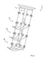
- FIG 1 illustrates a contact arrangement in a tap changer 4, which tap changer is illustrated in figure 2 .
- the tap changer 4 is a cylindrical tap changer 4, as illustrated in figure 2 , and comprises an outer cylinder 1 surrounding an interior shaft 2.
- the shaft 2 is rotatably arranged inside the cylinder 1.
- the tap changer is adapted for three phases and has terminal arrangements 10, 20, 30 for each of the three phases arranged at three heights following the circumference at three levels 10, 20, 30 of the cylinder 1.
- Each level includes a plurality of spaced apart tap terminals 11, 21, 31, on the outside of the cylinder 2, for providing connections to a plurality of different taps of regulating windings (not illustrated) of the transformer.
- Each of the terminals 11, 21, 31 around the cylinder provides an electrical connection to corresponding fixed contacts (3 in figure 1 ) inside the cylinder 2. These fixed contacts face inwardly towards the shaft 2 at the centre of the cylinder 1.
- the shaft 2 is provided with contact arrangements facing outward 12, 22, 32 towards the fixed contacts of the cylinder.
- the shaft includes three such contact arrangements 12, 22, 32, one for each phase.
- the contact arrangements 12, 22, 32 comprise mechanical contacts (9 in figure 1 ) attached to the shaft, and movable upon rotation of the shaft into contact with the fixed contacts (3) of the cylinder, so that a specific winding can be chosen by rotating the shaft 2 so that each contact arrangement 12, 22, 32 of the shaft is brought into mating contact with a corresponding fixed contact in the cylinder 1 for each phase.
- the contact arrangements 12, 22, 32 suitably also includes vacuum cells (not illustrated) in series with the mechanical contacts.
- Each contact arrangements 12, 22, 32 comprises at least two mechanical contacts, for example three mechanical contacts.
- the mechanical part (9) of one of the contact arrangements 12, 22, 33 of the shaft and the fixed contact 3 of the cylinder is illustrated in figure 1 .
- the fixed contact 3 inside the cylinder 1 is electrically connected to a tap terminal 11 on the outside of the cylinder.
- the contact arrangement of a the tap changer for a transformer comprises a fixed contact 3 extending from the cylinder and a mechanical contact 9 comprising contact fingers 4, 5 secured to the shaft (2 in figure 1 ) for mating the fixed contact 3 when the shaft is rotated.
- Each of the fingers is pivotally fixed to the shaft around a pivot axis 7, 8, each axis 7, 8 of each pivot extends in the circumferential direction of the shaft.
- the fingers 4, 5 are interconnected by a spring 8.
- the spring 8 is vertically arranged, i.e.
- the spring biases the fingers 4, 5 against the fixed contact 3.
- the mechanical contact is also provided with a finger support or rest 19 for the fingers 4, 5.
- the rest 19 provides a support for the fingers when disconnected from a fixed contact 3.
- the spring 6 forces the fingers 4, 5 towards each other until each of the fingers meet the rest 19.
- Each of the fingers 4, 5 are supported by the rest 19 until they during the rotation meet the next fixed contact 3 of the next tap 11.
- Each of the fingers 4, 5 are electrically connected by means of a cable (not illustrated) on the opposite side of the fixed contact, which cables are arranged at the shaft.
- each contact arrangement 12, 22, 32 suitably includes at least two pair of fingers 4, 5, one of which loses contact with the fixed contact 3 before the other, and connects to the next fixed contact 3, the next tap level (11, 21,31), before the other.
- Both, or all of these, mechanical contacts 9 with fingers 4, 5 comprises suitably one spring 6 for each pair of two fingers 4, 5.
Landscapes
- Rotary Switch, Piano Key Switch, And Lever Switch (AREA)
- Trip Switchboards (AREA)
Abstract
The present invention relates to providing electrical contact in a tap changer of a transformer. A tap changer with contacts is provided, which contacts contributes to a compensation of tolerances and wear. The tap changer comprises a cylinder (1), and a shaft (2), wherein the shaft is rotatably arranged inside the cylinder. The cylinder is provided with a plurality of fixed contacts (3), and the shaft is provided with a pair of contact fingers (4,5), which pair of contact fingers are arranged to selectively connect to a selected one of the fixed contacts of the cylinder, upon rotation of the shaft. The tap changer also comprises a spring (6) that is arranged to bias both fingers of the pair of contact fingers towards the selected fixed contact. Preferably, the tap changer comprises a support (19) for the contact fingers, the support being arranged to support the contact fingers when the pair of contact fingers is disconnected from the fixed contact.
Description
- The present invention relates generally to a tap changer of a transformer, and in particular to providing electrical contact in a tap changer of a transformer.
- Tap changers for selecting tap of a winding in a transformer exists in different configurations, such as cylindrical tap changers wherein an insulated cylinder is provided with fixed tap contacts at different tap levels and a rotatable shaft provided with corresponding movable contact parts is arranged inside the cylinder. Rotation of the shaft is performed to bring the movable contacts into contact with the a corresponding one of the fixed contacts of the cylinder.
- Mechanical contacts having a pair of two contact fingers have been used as movable contacts for connecting to a fixed contact between the fingers of the pair. An example of such a previously known mechanical contact is illustrated in
figure 3 . This contact includes two L-shaped fingers contact 43 of a surrounding cylinder. Thefixed contact 43 is connected on the opposite side to the terminals on the cylinder, whereas the each of thecontacts fingers respective axis 46, 47. To provide a reliable contact between each finger and the fixedcontact 43, eachfinger contact respective spring wall 50 secured to the shaft. - A disadvantage with such biased spring contacts where each
finger spring contact 43, results in a different contact pressure from each of thefingers contacts - It is an object of the invention to provide a tap changer for a transformer without the drawbacks of the prior art and provide a contact having contact fingers, which contact contributes to a compensation of tolerances and wear. The invention improves cylindrical tap changers for transformers comprising a cylinder, and a shaft, which shaft is rotatably arranged inside the cylinder, which cylinder is provided with a plurality of fixed contacts, and which shaft is provided with a pair of contact fingers, which pair of contact fingers is arranged to selectively connect to a selected one of the fixed contacts of the cylinder, upon rotation of the shaft.
- It is also an object of the invention to provide a tap changer having mechanical contacts of a reliable construction.
- It is also an object of the invention to provide mechanical contacts that contributes to facilitating the manufacturing of the tap changer.
- It is also an object of the invention to provide mechanical contacts that can align itself and balance the forces in the contact fingers when an offset due to wear or harsh manoeuvring otherwise would affect the electrical connection.
- For these purposes the invention provides a tap changer for a transformer having at least one pair of finger contacts for connection to a fixed contact, which fingers are biased towards the fixed contact when connected to the fixed contact. The invention improves cylindrical tap changers by arranging one spring to bias both fingers of the pair of contact fingers towards the selected fixed contact.
- Having the finger contacts interconnected by a common spring provide a reliable and adaptable bias of each of the fingers towards the fixed contact.
- The spring of such a solution can be relatively long, without requiring more space, e.g. one common spring for a pair of fingers can be twice as long as two springs arranged for a pair of fingers, without requiring more space. Having a longer length, a lower spring constant can be used, which results in a lower variation of the contact pressure due to tolerances and wear. Also, the common spring balances the contact forces so that the finger contacts can provide the same pressure even if, for example, the fixed contact is offset towards one of the fingers. Moreover, having one common spring for two fingers instead of two separate springs reduces the number of components and can reduce manufacturing costs, especially for tap changers having many contacts.
- Preferably, each of the contact fingers is pivotally and fixed to the shaft. The pivot can be used for leverage to control the pressure and having a space economic construction. Preferably, the pair of the contact fingers is fixed to the shaft, so that the pair moves together with the shaft, and preferably the contact fingers faces towards the cylinder. Preferably, the spring, the shaft and the cylinder extends in the same direction, which is the vertical direction inside the transformer. In this way the available space can be utilised effectively when the spring extends along the shaft. Preferably, the spring interconnects the fingers of the contact finger pair and extends from one of the contact fingers to the other contact finger.
- The tap changer can also include a support for the contact fingers, which support is arranged to support the contact fingers when the pair of contact fingers is disconnected from the fixed contacts.
- The tap changer of the invention is suitable for medium and high voltages, above 1 kV, for example 3 kV or higher voltage; or approximately 6 kV and higher.
- Generally, all terms used in the claims are to be interpreted according to their ordinary meaning in the technical field, unless explicitly defined otherwise herein. All references to "a/an/the element, apparatus, component, means, step, etc." are to be interpreted openly as referring to at least one instance of the element, apparatus, component, means, step, etc., unless explicitly stated otherwise. The steps of any method disclosed herein do not have to be performed in the exact order disclosed, unless explicitly stated.
-
-
Figure 1 illustrates a contact arrangement in a tap changer in accordance with the invention. -
Figure 2 illustrates a tap changer for a transformer of the cylindrical type suitable for the contact arrangement of the invention. -
Figure 3 illustrates a contact arrangement in a tap changer in accordance with prior art. -
Figure 1 illustrates a contact arrangement in atap changer 4, which tap changer is illustrated infigure 2 . Thetap changer 4 is acylindrical tap changer 4, as illustrated infigure 2 , and comprises an outer cylinder 1 surrounding aninterior shaft 2. Theshaft 2 is rotatably arranged inside the cylinder 1. The tap changer is adapted for three phases and hasterminal arrangements levels apart tap terminals cylinder 2, for providing connections to a plurality of different taps of regulating windings (not illustrated) of the transformer. Each of theterminals figure 1 ) inside thecylinder 2. These fixed contacts face inwardly towards theshaft 2 at the centre of the cylinder 1. Theshaft 2, in turn, is provided with contact arrangements facing outward 12, 22, 32 towards the fixed contacts of the cylinder. The shaft includes threesuch contact arrangements contact arrangements figure 1 ) attached to the shaft, and movable upon rotation of the shaft into contact with the fixed contacts (3) of the cylinder, so that a specific winding can be chosen by rotating theshaft 2 so that eachcontact arrangement contact arrangements contact arrangements - The mechanical part (9) of one of the
contact arrangements contact 3 of the cylinder is illustrated infigure 1 . The fixedcontact 3 inside the cylinder 1 is electrically connected to atap terminal 11 on the outside of the cylinder. The contact arrangement of a the tap changer for a transformer comprises afixed contact 3 extending from the cylinder and amechanical contact 9 comprisingcontact fingers figure 1 ) for mating thefixed contact 3 when the shaft is rotated. Each of the fingers is pivotally fixed to the shaft around apivot axis 7, 8, eachaxis 7, 8 of each pivot extends in the circumferential direction of the shaft. Thefingers spring 8. Thespring 8 is vertically arranged, i.e. in the direction of the shaft, between thefingers fingers contact 3. The mechanical contact is also provided with a finger support orrest 19 for thefingers rest 19 provides a support for the fingers when disconnected from a fixedcontact 3. When the shaft is rotated and themechanical contact 9 is opened, i.e. thefingers fixed contact 3 of the cylinder, the spring 6 forces thefingers rest 19. Each of thefingers fixed contact 3 of thenext tap 11. Each of thefingers contact arrangement fingers contact 3 before the other, and connects to the nextfixed contact 3, the next tap level (11, 21,31), before the other. Both, or all of these,mechanical contacts 9 withfingers fingers
Claims (7)
- A tap changer for a transformer comprising a cylinder (1), and a shaft (2),
the shaft being rotatably arranged inside the cylinder (1), the cylinder (1) being provided with a plurality of fixed contacts (3),
the shaft (2) being provided with a pair of contact fingers (4, 5),
which pair of contact fingers (4, 5) are arranged to selectively connect to a selected one of the fixed contacts (3) of the cylinder, upon rotation of the shaft (2),
characterised in comprising a spring (6) arranged to bias both fingers (4, 5) of the pair of contact fingers (4, 5) towards the selected fixed contact (3). - A tap changer according to claim 1, wherein each of the contact fingers (4, 5) is pivotally fixed.
- A tap changer according to claim 1 or 2, wherein the pair of the contact fingers (4, 5) is fixed to the shaft (2), and faces towards the cylinder (1).
- A tap changer according to any of the preceding claims, wherein the fixed contact (3) is arranged on the inside of the cylinder (1) facing inwards.
- A tap changer according to any of the proceeding claims, wherein the spring (6), the shaft (2) and cylinder (1) extends longitudinally in a vertical direction.
- A tap changer according to any of the preceding claims, wherein the spring (6) interconnects the fingers (4, 5) of the contact finger pair and extends from one of the contact fingers (4) to the other contact finger (5).
- A tap changer according to any of the preceding claims, comprising a support (19) for the contact fingers (4, 5), the support (19) being arranged to support the contact fingers (4, 5) when the pair of contact fingers (4, 5) is disconnected from the fixed contacts (3).
Priority Applications (2)
| Application Number | Priority Date | Filing Date | Title |
|---|---|---|---|
| EP09158243A EP2244273A1 (en) | 2009-04-20 | 2009-04-20 | Tap changer |
| PCT/IB2010/000937 WO2010122422A1 (en) | 2009-04-20 | 2010-04-22 | Tap charger |
Applications Claiming Priority (1)
| Application Number | Priority Date | Filing Date | Title |
|---|---|---|---|
| EP09158243A EP2244273A1 (en) | 2009-04-20 | 2009-04-20 | Tap changer |
Publications (1)
| Publication Number | Publication Date |
|---|---|
| EP2244273A1 true EP2244273A1 (en) | 2010-10-27 |
Family
ID=40984793
Family Applications (1)
| Application Number | Title | Priority Date | Filing Date |
|---|---|---|---|
| EP09158243A Withdrawn EP2244273A1 (en) | 2009-04-20 | 2009-04-20 | Tap changer |
Country Status (2)
| Country | Link |
|---|---|
| EP (1) | EP2244273A1 (en) |
| WO (1) | WO2010122422A1 (en) |
Cited By (2)
| Publication number | Priority date | Publication date | Assignee | Title |
|---|---|---|---|---|
| EP4629273A1 (en) * | 2024-04-02 | 2025-10-08 | Hitachi Energy Ltd | Static contact unit, contact system and tap changer |
| EP4651165A1 (en) * | 2024-05-14 | 2025-11-19 | Hitachi Energy Ltd | Static contact unit, contact system and tap changer |
Families Citing this family (1)
| Publication number | Priority date | Publication date | Assignee | Title |
|---|---|---|---|---|
| EP3098824B1 (en) * | 2015-05-27 | 2018-03-07 | ABB Schweiz AG | A contact unit for a tap changer and a tap selector comprising the contact unit |
Citations (6)
| Publication number | Priority date | Publication date | Assignee | Title |
|---|---|---|---|---|
| CH420335A (en) * | 1964-06-04 | 1966-09-15 | Siemens Ag | Movable selector contact of tap changers for heavy current, especially for transformers |
| DE1538102A1 (en) * | 1965-09-15 | 1969-11-06 | Siemens Ag | Contact arrangement |
| BE823748A (en) * | 1974-12-23 | 1975-06-23 | Acec | FIXED CONTACT AND MOBILE CONTACT ASSEMBLY FOR ELECTRICAL TRANSFORMER TAKING CHANGER. |
| JPS5086628U (en) * | 1973-12-14 | 1975-07-23 | ||
| JPS5086629U (en) * | 1973-12-14 | 1975-07-23 | ||
| JPS5582420A (en) * | 1978-12-14 | 1980-06-21 | Fuji Electric Co Ltd | Tap selector |
Family Cites Families (3)
| Publication number | Priority date | Publication date | Assignee | Title |
|---|---|---|---|---|
| DE920732C (en) * | 1942-04-23 | 1954-11-29 | Siemens Ag | Contact arrangement for electrical switches, especially for tap changers that switch without current |
| CH337255A (en) * | 1955-11-12 | 1959-03-31 | Bbc Brown Boveri & Cie | Switching device with two parallel contact paths |
| GB1051945A (en) * | 1963-09-18 | 1900-01-01 |
-
2009
- 2009-04-20 EP EP09158243A patent/EP2244273A1/en not_active Withdrawn
-
2010
- 2010-04-22 WO PCT/IB2010/000937 patent/WO2010122422A1/en not_active Ceased
Patent Citations (6)
| Publication number | Priority date | Publication date | Assignee | Title |
|---|---|---|---|---|
| CH420335A (en) * | 1964-06-04 | 1966-09-15 | Siemens Ag | Movable selector contact of tap changers for heavy current, especially for transformers |
| DE1538102A1 (en) * | 1965-09-15 | 1969-11-06 | Siemens Ag | Contact arrangement |
| JPS5086628U (en) * | 1973-12-14 | 1975-07-23 | ||
| JPS5086629U (en) * | 1973-12-14 | 1975-07-23 | ||
| BE823748A (en) * | 1974-12-23 | 1975-06-23 | Acec | FIXED CONTACT AND MOBILE CONTACT ASSEMBLY FOR ELECTRICAL TRANSFORMER TAKING CHANGER. |
| JPS5582420A (en) * | 1978-12-14 | 1980-06-21 | Fuji Electric Co Ltd | Tap selector |
Cited By (4)
| Publication number | Priority date | Publication date | Assignee | Title |
|---|---|---|---|---|
| EP4629273A1 (en) * | 2024-04-02 | 2025-10-08 | Hitachi Energy Ltd | Static contact unit, contact system and tap changer |
| WO2025209755A1 (en) * | 2024-04-02 | 2025-10-09 | Hitachi Energy Ltd | Static contact unit, contact system and tap changer |
| EP4651165A1 (en) * | 2024-05-14 | 2025-11-19 | Hitachi Energy Ltd | Static contact unit, contact system and tap changer |
| WO2025237684A1 (en) | 2024-05-14 | 2025-11-20 | Hitachi Energy Ltd | Static contact unit, contact system and tap changer |
Also Published As
| Publication number | Publication date |
|---|---|
| WO2010122422A1 (en) | 2010-10-28 |
Similar Documents
| Publication | Publication Date | Title |
|---|---|---|
| US20140085028A1 (en) | Tap changer and vacuum interrupter for such a tap changer | |
| KR20140060296A (en) | On-load tap changer | |
| JP6586461B2 (en) | Switching device having two on-load tap changers, electrical equipment having the switching device, and methods of using them | |
| US10418196B2 (en) | On-load tap changer device | |
| US9287036B2 (en) | Supplementary transformer winding | |
| US7977589B2 (en) | Measuring contact sequence in a tap changer | |
| CN103026433A (en) | On-load tap changer | |
| US11996256B2 (en) | Switching system for an on-load tap changer, on-load tap changer and method for switching a tap connection of an on-load tap changer | |
| EP2244273A1 (en) | Tap changer | |
| JP2017532775A (en) | Switching device for control transformer, especially pole switching device | |
| US20240249893A1 (en) | On-load tap changer with positioning device and method for assembling an on-load tap changer | |
| JP6580071B2 (en) | Switching device for a tapped transformer and method for operating such a switching device | |
| US11087913B2 (en) | Transformer system | |
| CN105960694A (en) | On-load tap changer according to the reactor switching principle | |
| EP2736140B1 (en) | Adjustable reactive power compensator for power networks | |
| Oates et al. | Tap changer for distributed power | |
| US11594368B2 (en) | Assembly for connection to a high-voltage system with adjustable impedance | |
| US20160293325A1 (en) | Electrical switching system for a three-phase network | |
| CN114026665B (en) | Multiphase selector-preselector device for on-load tap changers | |
| CN1933055B (en) | Non-field cage-shape tap changer for transformer | |
| CN206711735U (en) | A kind of U.S. special Y D change-over switches of change | |
| US12400812B2 (en) | Inline disconnect for multiphase electric utility line applications | |
| US2185719A (en) | Circuit breaker | |
| KR20160088565A (en) | Zero Load Tap For Explosion Transformer | |
| HK1187734B (en) | Tap changer having vacuum interrupters |
Legal Events
| Date | Code | Title | Description |
|---|---|---|---|
| PUAI | Public reference made under article 153(3) epc to a published international application that has entered the european phase |
Free format text: ORIGINAL CODE: 0009012 |
|
| 17P | Request for examination filed |
Effective date: 20090420 |
|
| AK | Designated contracting states |
Kind code of ref document: A1 Designated state(s): AT BE BG CH CY CZ DE DK EE ES FI FR GB GR HR HU IE IS IT LI LT LU LV MC MK MT NL NO PL PT RO SE SI SK TR |
|
| STAA | Information on the status of an ep patent application or granted ep patent |
Free format text: STATUS: THE APPLICATION HAS BEEN WITHDRAWN |
|
| 18W | Application withdrawn |
Effective date: 20110120 |