EP2243990A1 - Solenoid type electromagnetic valve device - Google Patents
Solenoid type electromagnetic valve device Download PDFInfo
- Publication number
- EP2243990A1 EP2243990A1 EP09822003A EP09822003A EP2243990A1 EP 2243990 A1 EP2243990 A1 EP 2243990A1 EP 09822003 A EP09822003 A EP 09822003A EP 09822003 A EP09822003 A EP 09822003A EP 2243990 A1 EP2243990 A1 EP 2243990A1
- Authority
- EP
- European Patent Office
- Prior art keywords
- side face
- solenoid
- power supply
- solenoid core
- supply body
- Prior art date
- Legal status (The legal status is an assumption and is not a legal conclusion. Google has not performed a legal analysis and makes no representation as to the accuracy of the status listed.)
- Granted
Links
Images


Classifications
-
- F—MECHANICAL ENGINEERING; LIGHTING; HEATING; WEAPONS; BLASTING
- F02—COMBUSTION ENGINES; HOT-GAS OR COMBUSTION-PRODUCT ENGINE PLANTS
- F02M—SUPPLYING COMBUSTION ENGINES IN GENERAL WITH COMBUSTIBLE MIXTURES OR CONSTITUENTS THEREOF
- F02M47/00—Fuel-injection apparatus operated cyclically with fuel-injection valves actuated by fluid pressure
- F02M47/02—Fuel-injection apparatus operated cyclically with fuel-injection valves actuated by fluid pressure of accumulator-injector type, i.e. having fuel pressure of accumulator tending to open, and fuel pressure in other chamber tending to close, injection valves and having means for periodically releasing that closing pressure
- F02M47/027—Electrically actuated valves draining the chamber to release the closing pressure
-
- F—MECHANICAL ENGINEERING; LIGHTING; HEATING; WEAPONS; BLASTING
- F02—COMBUSTION ENGINES; HOT-GAS OR COMBUSTION-PRODUCT ENGINE PLANTS
- F02M—SUPPLYING COMBUSTION ENGINES IN GENERAL WITH COMBUSTIBLE MIXTURES OR CONSTITUENTS THEREOF
- F02M61/00—Fuel-injectors not provided for in groups F02M39/00 - F02M57/00 or F02M67/00
- F02M61/16—Details not provided for in, or of interest apart from, the apparatus of groups F02M61/02 - F02M61/14
- F02M61/166—Selection of particular materials
-
- F—MECHANICAL ENGINEERING; LIGHTING; HEATING; WEAPONS; BLASTING
- F02—COMBUSTION ENGINES; HOT-GAS OR COMBUSTION-PRODUCT ENGINE PLANTS
- F02M—SUPPLYING COMBUSTION ENGINES IN GENERAL WITH COMBUSTIBLE MIXTURES OR CONSTITUENTS THEREOF
- F02M61/00—Fuel-injectors not provided for in groups F02M39/00 - F02M57/00 or F02M67/00
- F02M61/16—Details not provided for in, or of interest apart from, the apparatus of groups F02M61/02 - F02M61/14
- F02M61/168—Assembling; Disassembling; Manufacturing; Adjusting
-
- F—MECHANICAL ENGINEERING; LIGHTING; HEATING; WEAPONS; BLASTING
- F02—COMBUSTION ENGINES; HOT-GAS OR COMBUSTION-PRODUCT ENGINE PLANTS
- F02M—SUPPLYING COMBUSTION ENGINES IN GENERAL WITH COMBUSTIBLE MIXTURES OR CONSTITUENTS THEREOF
- F02M63/00—Other fuel-injection apparatus having pertinent characteristics not provided for in groups F02M39/00 - F02M57/00 or F02M67/00; Details, component parts, or accessories of fuel-injection apparatus, not provided for in, or of interest apart from, the apparatus of groups F02M39/00 - F02M61/00 or F02M67/00; Combination of fuel pump with other devices, e.g. lubricating oil pump
- F02M63/0012—Valves
- F02M63/0014—Valves characterised by the valve actuating means
- F02M63/0015—Valves characterised by the valve actuating means electrical, e.g. using solenoid
- F02M63/0017—Valves characterised by the valve actuating means electrical, e.g. using solenoid using electromagnetic operating means
- F02M63/0019—Valves characterised by the valve actuating means electrical, e.g. using solenoid using electromagnetic operating means characterised by the arrangement of electromagnets or fixed armatures
-
- H—ELECTRICITY
- H01—ELECTRIC ELEMENTS
- H01F—MAGNETS; INDUCTANCES; TRANSFORMERS; SELECTION OF MATERIALS FOR THEIR MAGNETIC PROPERTIES
- H01F7/00—Magnets
- H01F7/06—Electromagnets; Actuators including electromagnets
- H01F7/08—Electromagnets; Actuators including electromagnets with armatures
- H01F7/128—Encapsulating, encasing or sealing
-
- F—MECHANICAL ENGINEERING; LIGHTING; HEATING; WEAPONS; BLASTING
- F02—COMBUSTION ENGINES; HOT-GAS OR COMBUSTION-PRODUCT ENGINE PLANTS
- F02M—SUPPLYING COMBUSTION ENGINES IN GENERAL WITH COMBUSTIBLE MIXTURES OR CONSTITUENTS THEREOF
- F02M2200/00—Details of fuel-injection apparatus, not otherwise provided for
- F02M2200/02—Fuel-injection apparatus having means for reducing wear
-
- F—MECHANICAL ENGINEERING; LIGHTING; HEATING; WEAPONS; BLASTING
- F02—COMBUSTION ENGINES; HOT-GAS OR COMBUSTION-PRODUCT ENGINE PLANTS
- F02M—SUPPLYING COMBUSTION ENGINES IN GENERAL WITH COMBUSTIBLE MIXTURES OR CONSTITUENTS THEREOF
- F02M2200/00—Details of fuel-injection apparatus, not otherwise provided for
- F02M2200/04—Fuel-injection apparatus having means for avoiding effect of cavitation, e.g. erosion
-
- F—MECHANICAL ENGINEERING; LIGHTING; HEATING; WEAPONS; BLASTING
- F02—COMBUSTION ENGINES; HOT-GAS OR COMBUSTION-PRODUCT ENGINE PLANTS
- F02M—SUPPLYING COMBUSTION ENGINES IN GENERAL WITH COMBUSTIBLE MIXTURES OR CONSTITUENTS THEREOF
- F02M2200/00—Details of fuel-injection apparatus, not otherwise provided for
- F02M2200/80—Fuel injection apparatus manufacture, repair or assembly
- F02M2200/8046—Fuel injection apparatus manufacture, repair or assembly the manufacture involving injection moulding, e.g. of plastic or metal
Definitions
- the present invention relates to an erosion-protecting device for protecting a solenoid type electromagnetic valve from erosion thereof;
- the solenoid type electromagnetic valve is provided with a plate-type armature that is connected to an end part of a valve body which opens and closes a liquid passage (a fuel passage in a case of a fuel injection device), as well as, a solenoid core power supply body that is provided with a solenoidal coil integrated with the solenoid core in a solenoid case that is filled with the liquid.
- a solenoid type electromagnetic configured such that a plate-type armature connected to an end part of a valve body which opens and closes a fuel passage and a solenoid core power supply body comprising a solenoidal coil integrated with the solenoid core in a solenoid case that is filled up with the fuel are provided, and an attracting side face of the solenoid core power supply body attracts an armature when current is conducted through the solenoidal coil, while the attraction force between the attracting side face of the solenoid core power supply body and the attracted side face of the armature is released when the current conducted through the coil is cut off, are often used for fuel injection devices of diesel engines.
- Fig. 3 shows an example of the solenoid type electromagnetic valve device according to a conventional technology.
- the solenoid type electromagnetic valve device as shown in Fig. 3 comprises a plate-type armature 6 that is directly connected to an end part of a control valve (not shown) for opening and closing a fuel passage (not shown), as well as a solenoid core power supply body 101 that is provided with a solenoid core 11 integrated with a solenoidal coil 3 and housed in a solenoid case 2 of a box shape filled up with the fuel oil.
- the solenoidal coil 3 is configured so that the coil 3 is placed around a middle protrusion part of an E-shaped solenoid core 11, the middle protrusion part being formed between a pair of grooves 11a as shown in Fig. 2 ; because of the pair of grooves 11a, the E-shape of the solenoid core 11 is formed; the interstices between the solenoid core 11 and the solenoidal coil 3 are filled with an insulation resin material that can be solidified after being filled.
- the solenoid core power supply body 101 is housed in a housing 1; the housing 1 is fastened to a valve case 1t via an intermediate piece 1s having a hollow space therein.
- the gap between the attracting side face 15 and the attracted side face 6b varies within a range of the clearance level of 0.1 mm; and the armature is operated with high-speed responsivity; under such a condition, a pressure change from a positive pressure to a negative pressure and vice versa is repeated in the gap between the attracting side face 15 and the attracted side face 6b causing cavitation phenomena to occur in the gap.
- JP2008-151082 discloses a solenoid type electromagnetic valve device comprising a plate-type armature connected to an end part of a valve body which opens and closes a fuel passage and a solenoid core power supply body comprising a solenoidal coil integrated with the solenoid core in a solenoid case that is filled up with the fuel.
- the present invention aims at providing a solenoid type electromagnetic valve with high-speed responsivity and enhanced durability, thereby the valve can be protected from the erosion damage due to cavitation, without losing the high-speed responsivity.
- the present invention discloses a solenoid type electromagnetic valve including a plate-type armature connected to an end part of a valve body which opens and closes a liquid passage; and a solenoid core power supply body comprising a solenoidal coil integrated with the solenoid core in a solenoid case that is filled up with a liquid, the solenoid type electromagnetic valve is configured such that an attracting side face of the solenoid core power supply body attracts an armature when current is conducted through the solenoidal coil, while the attraction force between the attracting side face of the solenoid core power supply body and the attracted side face of the armature is released when the current conducted through the coil is cut off; wherein at least one plate member of nonmagnetic material is fitted to the attracting side face of the solenoid core power supply body, the attracting side face being opposed to the attracted side face, fluid insulation resin is filled into interstices between the solenoid case and solenoid core power supply body, and the filled insulation resin is solid
- a preferable embodiment regarding the above disclosure is the solenoid type electromagnetic valve, wherein the material of the nonmagnetic plate member is selected from either one of nonmagnetic stainless steel, aluminum alloy or ceramic material those which have higher deformation temperature and higher hardness than those of the material of the insulation resin.
- the solenoid type electromagnetic valve wherein the solenoidal coil of the solenoid core power supply body is wound around a middle protrusion part of the solenoid core formed in an E-shape, and an outlet side of the solenoidal coil facing the attracted side face of the armature is covered by at least one plate member of nonmagnetic material being fitted and fixed thereto.
- the above-disclosed solenoid type electromagnetic valve provided with the solenoidal coil wound around the middle protrusion part of the solenoid core formed in an E-shape, at least one plate member of nonmagnetic material is fitted to the attracting side face of the solenoid core power supply body so that the grooves of the E-shaped solenoid core are covered with the plate members of nonmagnetic material from the outlet side 11b of the solenoidal coil wound around the middle protrusion part of the E-shaped solenoid core.
- each of the nonmagnetic material plate members shields magnetism without hindering the function of the solenoidal coil cover the outlet side of the solenoidal coil facing the attracted side face of the armature where is exposed to strong cavitations, the solenoid type electromagnetic valve can be protected from the erosion damage due to cavitations without losing high-speed responsivity.
- the plate members of nonmagnetic material seal the grooves of the E-shaped solenoid core integrated with the solenoidal coil, from the outlet side of the solenoidal coil wound around the middle protrusion part of the E-shaped solenoid core, the outlet side facing the attracted side face of the armature.
- the reason is that the (fuel) oil, once absorbed around the wires of the solenoidal coil in the grooves of the E-shaped solenoid core integrated with the solenoidal coil, is prone to staying there as well as deteriorating the resin filled into the interstice in the grooves.
- the material of the plate member may be either of nonmagnetic stainless steel, aluminum alloy or ceramic material.
- Fig. 1 shows a cross-section of a solenoid type electromagnetic valve according to an embodiment of the present invention.
- a solenoid device 100 comprises a plate-type armature 6 that is directly connected to an end part of a control valve (not shown) for opening and closing a fuel passage (not shown), as well as a solenoid core power supply body 101 that is provided with a solenoid core 11 integrated with a solenoidal coil 3 and housed in a solenoid case 2 of a box shape filled up with the fuel oil.
- the solenoidal coil 3 is configured to be wound around a middle protrusion part of the solenoid core 11 which is formed in an E-shape, the middle protrusion part being formed between a pair of grooves 11a, and the solenoidal coil 3 is placed so that the coil goes through the pair of grooves 11a and a pair of clearances between the protrusion part and the solenoid case 2.
- the solenoid core power supply body 101 is housed in a housing 1, which is fastened to a valve case (a mechanical valve part case) It via an intermediate piece 1s having a hollow space therein.
- the configuration as described above is the same as the configuration of the conventional technology.
- the present invention provides a solenoid type electromagnetic valve of high-speed responsivity and enhanced durability thereby the valve can be protected from the erosion damage due to cavitations between the attracting side face 15 of the solenoid core power supply body 101 and the attracted side face 6b of the armature 6.
- the plate members 5 of nonmagnetic material cover the grooves 11a of the E-shaped solenoid core 11 from the outlet side 11b of the solenoidal coil 3 wound around the middle protrusion part of the E-shaped solenoid core 11, the outlet side facing the attracted side face 6b of the armature 6.
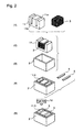
- Fig. 2 sequentially shows an assembly procedure as to the parts of the solenoid type electromagnetic valve according to an embodiment of the present invention.
- the solenoidal coil 3 is wound through the grooves 11a of the solenoid core 11 having a form of E-shape (step (1)), and the solenoid core 11 integrated with solenoidal coil 3 is formed (step (2)).
- step (1) the solenoid core 11 into which the solenoidal coil 3 is fitted in the E-shape arrangement is housed in the solenoid case 2 (step (3)).
- thermoplastic nonmagnetic resin (fluid resin) 12 is filled into the interstice between the solenoid case 2 and the above-described assembled member into which the plate members 5 of nonmagnetic material are press-fitted, and the filled resin is solidified (the step (5)).
- the grooves 11a of the E-shaped solenoid core 11 are covered with the plate members 5 of nonmagnetic material from the outlet side 11b of the solenoidal coil 3 wound around the middle protrusion part of the E-shaped solenoid core 11. Since the nonmagnetic material plate members 5 each of which has a higher softening point and higher hardness than those of the thermoplastic nonmagnetic resin, and which shields magnetism without hindering the function of the solenoidal coil 3 cover the outlet side 11b of the solenoidal coil 3 facing the attracted side face 6b of the armature 6 where is exposed to strong cavitations, the solenoid type electromagnetic valve can be protected from the erosion damage due to cavitations without losing high-speed responsivity.
- the plate members 5 of nonmagnetic material cover the grooves 11a of the E-shaped solenoid core 11 integrated with the solenoidal coil 3, from the outlet side 11b of the solenoidal coil 3 wound around the middle protrusion part of the E-shaped solenoid core 11, the outlet side 11b facing the attracted side face 6b of the armature 6.
- the reason is that the fuel oil, once absorbed around the wires of the solenoidal coil 3 in the grooves 11a of the E-shaped solenoid core 11, is prone to stay there as well as deteriorate the resin filled into the interstice in the grooves 11a.
- the material of the plate member 5 of nonmagnetic material it may be selected as one of nonmagnetic stainless steel, aluminum alloy or ceramic material.
- the present invention can provide solenoid type electromagnetic valve of high-speed responsivity and enhanced durability thereby the valve can be protected from the erosion damage due to cavitation, without losing high-speed responsivity.
Landscapes
- Engineering & Computer Science (AREA)
- Physics & Mathematics (AREA)
- Electromagnetism (AREA)
- Combustion & Propulsion (AREA)
- Mechanical Engineering (AREA)
- General Engineering & Computer Science (AREA)
- Chemical & Material Sciences (AREA)
- Fluid Mechanics (AREA)
- Power Engineering (AREA)
- Manufacturing & Machinery (AREA)
- Magnetically Actuated Valves (AREA)
- Fuel-Injection Apparatus (AREA)
- Electromagnets (AREA)
Abstract
Description
- The present invention relates to an erosion-protecting device for protecting a solenoid type electromagnetic valve from erosion thereof; the solenoid type electromagnetic valve is provided with a plate-type armature that is connected to an end part of a valve body which opens and closes a liquid passage (a fuel passage in a case of a fuel injection device), as well as, a solenoid core power supply body that is provided with a solenoidal coil integrated with the solenoid core in a solenoid case that is filled with the liquid.
- A solenoid type electromagnetic configured such that a plate-type armature connected to an end part of a valve body which opens and closes a fuel passage and a solenoid core power supply body comprising a solenoidal coil integrated with the solenoid core in a solenoid case that is filled up with the fuel are provided, and an attracting side face of the solenoid core power supply body attracts an armature when current is conducted through the solenoidal coil, while the attraction force between the attracting side face of the solenoid core power supply body and the attracted side face of the armature is released when the current conducted through the coil is cut off, are often used for fuel injection devices of diesel engines.
-
Fig. 3 shows an example of the solenoid type electromagnetic valve device according to a conventional technology.
The solenoid type electromagnetic valve device as shown inFig. 3 comprises a plate-type armature 6 that is directly connected to an end part of a control valve (not shown) for opening and closing a fuel passage (not shown), as well as a solenoid corepower supply body 101 that is provided with asolenoid core 11 integrated with asolenoidal coil 3 and housed in asolenoid case 2 of a box shape filled up with the fuel oil.
In the solenoid corepower supply body 101, thesolenoidal coil 3 is configured so that thecoil 3 is placed around a middle protrusion part of anE-shaped solenoid core 11, the middle protrusion part being formed between a pair ofgrooves 11a as shown inFig. 2 ; because of the pair ofgrooves 11a, the E-shape of thesolenoid core 11 is formed; the interstices between thesolenoid core 11 and thesolenoidal coil 3 are filled with an insulation resin material that can be solidified after being filled.
The solenoid corepower supply body 101 is housed in ahousing 1; thehousing 1 is fastened to avalve case 1t via anintermediate piece 1s having a hollow space therein. - When the
solenoidal coil 3 is conducted with current, there arises an attraction force between an attractingside face 15 of the solenoid corepower supply body 101, namely the lower end surface thereof, and an attractedside face 6b of thearmature 6. The attraction force makes the attractingside face 15 attract the attractedside face 6b in a direction toward theside face 15 against the counterforce due to aspring 8. In addition, the gap between the attractingside face 15 and the attractedside face 6b is approximately 0.1 mm.
In this way, the control valve (not shown) that is fixed to thearmature 6 moves (toward in the Y-arrow direction inFig.1 ) and closes the fuel passage (not shown) so that the fuel in a control room (not shown) is pressurized.
In the next place, when the current conducted through thesolenoidal coil 3 is cut off, the attraction force between the attractingside face 15 of the solenoid corepower supply body 101 and the attractedside face 6b of thearmature 6 is released so that the control valve (not shown) opens and the pressure in the fuel passage (not shown) is released. - As described above, when the solenoid core
power supply body 101 is actuated, the gap between the attractingside face 15 and the attractedside face 6b varies within a range of the clearance level of 0.1 mm; and the armature is operated with high-speed responsivity; under such a condition, a pressure change from a positive pressure to a negative pressure and vice versa is repeated in the gap between the attractingside face 15 and the attractedside face 6b causing cavitation phenomena to occur in the gap. - A patent reference (
JP2008-151082 - In the device disclosed by the patent reference, as shown in
Fig. 3 , when the above-described control valve closes, the pressure increases in the small gap between the attractingside face 15 of the solenoid corepower supply body 101 and the attractedside face 6b of thearmature 6. Because of this pressure increase, the control valve is kept under a locked condition for preventing the control valve from bouncing; hence, as soon as the control valve is lifted and opened, the pressure in the space in which thearmature 6 is housed increases; further, the pressure in the above-described small gap rapidly decreases causing the fluid (liquid, or usually fuel in a case of fuel injection devices) in the housing space of thearmature 6 to flow into the small gap. As a result, the surfaces facing the small gap space between the solenoid corepower supply body 101 and thearmature 6 are prone to be damaged from the cavitation erosion. - Partly because the magnetic core (the iron core) of the solenoid core
power supply body 101 is fixed in thesolenoid case 2 by filling magnetism- insulation resin material, the erosion damage caused in the event of the cavitation is prone to finally causing a difficulty that is the breaking of thesolenoidal coil 3.
Further, according to the disclosure of the patent reference (JP2008-151082 - PATENT REFERENCE 1:
JP2008-151082 - In view of the difficulties in the conventional technology, the present invention aims at providing a solenoid type electromagnetic valve with high-speed responsivity and enhanced durability, thereby the valve can be protected from the erosion damage due to cavitation, without losing the high-speed responsivity.
- In order to overcome the above-described difficulties, the present invention discloses a solenoid type electromagnetic valve including
a plate-type armature connected to an end part of a valve body which opens and closes a liquid passage; and
a solenoid core power supply body comprising a solenoidal coil integrated with the solenoid core in a solenoid case that is filled up with a liquid,
the solenoid type electromagnetic valve is configured such that an attracting side face of the solenoid core power supply body attracts an armature when current is conducted through the solenoidal coil, while the attraction force between the attracting side face of the solenoid core power supply body and the attracted side face of the armature is released when the current conducted through the coil is cut off;
wherein at least one plate member of nonmagnetic material is fitted to the attracting side face of the solenoid core power supply body, the attracting side face being opposed to the attracted side face, fluid insulation resin is filled into interstices between the solenoid case and solenoid core power supply body, and the filled insulation resin is solidified. - A preferable embodiment regarding the above disclosure is the solenoid type electromagnetic valve, wherein the material of the nonmagnetic plate member is selected from either one of nonmagnetic stainless steel, aluminum alloy or ceramic material those which have higher deformation temperature and higher hardness than those of the material of the insulation resin.
- Another preferable embodiment regarding the above disclosure is the solenoid type electromagnetic valve, wherein the solenoidal coil of the solenoid core power supply body is wound around a middle protrusion part of the solenoid core formed in an E-shape, and an outlet side of the solenoidal coil facing the attracted side face of the armature is covered by at least one plate member of nonmagnetic material being fitted and fixed thereto.
- More concretely, in the above-disclosed solenoid type electromagnetic valve provided with the solenoidal coil wound around the middle protrusion part of the solenoid core formed in an E-shape, at least one plate member of nonmagnetic material is fitted to the attracting side face of the solenoid core power supply body so that the grooves of the E-shaped solenoid core are covered with the plate members of nonmagnetic material from the
outlet side 11b of the solenoidal coil wound around the middle protrusion part of the E-shaped solenoid core. Since each of the nonmagnetic material plate members shields magnetism without hindering the function of the solenoidal coil cover the outlet side of the solenoidal coil facing the attracted side face of the armature where is exposed to strong cavitations, the solenoid type electromagnetic valve can be protected from the erosion damage due to cavitations without losing high-speed responsivity. - Further, it is preferable and effective that the plate members of nonmagnetic material seal the grooves of the E-shaped solenoid core integrated with the solenoidal coil, from the outlet side of the solenoidal coil wound around the middle protrusion part of the E-shaped solenoid core, the outlet side facing the attracted side face of the armature. The reason is that the (fuel) oil, once absorbed around the wires of the solenoidal coil in the grooves of the E-shaped solenoid core integrated with the solenoidal coil, is prone to staying there as well as deteriorating the resin filled into the interstice in the grooves.
- Further, the material of the plate member may be either of nonmagnetic stainless steel, aluminum alloy or ceramic material. By press-fitting the plate members made of either of these materials and solidifying the filled magnetism-insulation resin, the surface of the solenoid core power supply body, which surface is prone to being exposed to heat attack (besides erosion attack), can be certainly protected by the plate members of nonmagnetic material.
-
-
Fig. 1 shows a cross-section of a solenoid type electromagnetic valve according to an embodiment of the present invention; -
Fig. 2 sequentially shows an assembly procedure as to the parts of the solenoid type electromagnetic valve according to an embodiment of the present invention; -
Fig. 3 shows an example of a solenoid type electromagnetic valve according to a conventional technology. - Hereafter, the present invention will be described in detail with reference to the embodiments shown in the figures. However, the dimensions, materials, shape, the relative placement and so on of a component described in these embodiments shall not be construed as limiting the scope of the invention thereto, unless especially specific mention is made.
-
Fig. 1 shows a cross-section of a solenoid type electromagnetic valve according to an embodiment of the present invention. InFig. 1 , asolenoid device 100 comprises a plate-type armature 6 that is directly connected to an end part of a control valve (not shown) for opening and closing a fuel passage (not shown), as well as a solenoid corepower supply body 101 that is provided with asolenoid core 11 integrated with asolenoidal coil 3 and housed in asolenoid case 2 of a box shape filled up with the fuel oil. - In the solenoid core
power supply body 101, thesolenoidal coil 3 is configured to be wound around a middle protrusion part of thesolenoid core 11 which is formed in an E-shape, the middle protrusion part being formed between a pair ofgrooves 11a, and thesolenoidal coil 3 is placed so that the coil goes through the pair ofgrooves 11a and a pair of clearances between the protrusion part and thesolenoid case 2.
In addition, the solenoid corepower supply body 101 is housed in ahousing 1, which is fastened to a valve case (a mechanical valve part case) It via anintermediate piece 1s having a hollow space therein. - When the
solenoidal coil 3 is conducted with current, there arises an attraction force between an attractingside face 15 of the solenoid corepower supply body 101, namely the lower end surface thereof, and an attractedside face 6b of thearmature 6. The attraction force makes the attractingside face 15 attract the attractedside face 6b in a direction toward theside face 15 against the counterforce due to aspring 8. In addition, the gap between the attractingside face 15 and the attractedside face 6b is approximately 0.1 mm.
In this way, the control valve (not shown) that is fixed to thearmature 6 moves (toward in the Y-arrow direction inFig.1 ) and closes the fuel passage (not shown) so that the fuel in a control room (not shown) is pressurized. - On the other hand, when the current conducted through the
coil 3 is cut off, the attraction force between the attractingside face 15 of the solenoid corepower supply body 101 and the attractedside face 6b of thearmature 6 is released so that the control valve (not shown) opens and the pressure in the fuel passage (not shown) is released. - The configuration as described above is the same as the configuration of the conventional technology.
The present invention provides a solenoid type electromagnetic valve of high-speed responsivity and enhanced durability thereby the valve can be protected from the erosion damage due to cavitations between the attractingside face 15 of the solenoid corepower supply body 101 and the attractedside face 6b of thearmature 6. - In the present invention as shown in
Fig.1 , on the side of the attractingside face 15 that is opposed to the attractedside face 6b, at least oneplate member 5, which is formed as a band plate of nonmagnetic material, is fitted.
In other words, theplate members 5 of nonmagnetic material cover thegrooves 11a of theE-shaped solenoid core 11 from theoutlet side 11b of thesolenoidal coil 3 wound around the middle protrusion part of theE-shaped solenoid core 11, the outlet side facing the attractedside face 6b of thearmature 6. -
Fig. 2 sequentially shows an assembly procedure as to the parts of the solenoid type electromagnetic valve according to an embodiment of the present invention. InFig. 2 , thesolenoidal coil 3 is wound through thegrooves 11a of thesolenoid core 11 having a form of E-shape (step (1)), and thesolenoid core 11 integrated withsolenoidal coil 3 is formed (step (2)). Next in order, thesolenoid core 11 into which thesolenoidal coil 3 is fitted in the E-shape arrangement is housed in the solenoid case 2 (step (3)). - In the next place, the
plate members 5 of nonmagnetic material that are prepared apart from the steps inFig. 2 are press-fitted into the assembled member consisting of thesolenoid core 11 and the solenoidal coil 3 (the step (4)).
After that, thermoplastic nonmagnetic resin (fluid resin) 12 is filled into the interstice between thesolenoid case 2 and the above-described assembled member into which theplate members 5 of nonmagnetic material are press-fitted, and the filled resin is solidified (the step (5)). - According to the embodiment as described above, the
grooves 11a of theE-shaped solenoid core 11 are covered with theplate members 5 of nonmagnetic material from theoutlet side 11b of thesolenoidal coil 3 wound around the middle protrusion part of theE-shaped solenoid core 11. Since the nonmagneticmaterial plate members 5 each of which has a higher softening point and higher hardness than those of the thermoplastic nonmagnetic resin, and which shields magnetism without hindering the function of thesolenoidal coil 3 cover theoutlet side 11b of thesolenoidal coil 3 facing the attractedside face 6b of thearmature 6 where is exposed to strong cavitations, the solenoid type electromagnetic valve can be protected from the erosion damage due to cavitations without losing high-speed responsivity. - Further, it is effective that the
plate members 5 of nonmagnetic material cover thegrooves 11a of theE-shaped solenoid core 11 integrated with thesolenoidal coil 3, from theoutlet side 11b of thesolenoidal coil 3 wound around the middle protrusion part of theE-shaped solenoid core 11, theoutlet side 11b facing the attractedside face 6b of thearmature 6. The reason is that the fuel oil, once absorbed around the wires of thesolenoidal coil 3 in thegrooves 11a of theE-shaped solenoid core 11, is prone to stay there as well as deteriorate the resin filled into the interstice in thegrooves 11a. - As for the material of the
plate member 5 of nonmagnetic material, it may be selected as one of nonmagnetic stainless steel, aluminum alloy or ceramic material. By press-fitting theplate members 5 made of either of these materials and solidifying the filled magnetism-insulation resin, the surface of the solenoid corepower supply body 101 exposed to heat attack besides erosion attack can be certainly protected by theplate members 5 of nonmagnetic material. - The present invention can provide solenoid type electromagnetic valve of high-speed responsivity and enhanced durability thereby the valve can be protected from the erosion damage due to cavitation, without losing high-speed responsivity.
Claims (3)
- A solenoid type electromagnetic valve including
a plate-type armature connected to an end part of a valve body which opens and closes a liquid passage; and
a solenoid core power supply body comprising a solenoidal coil integrated with a solenoid core in a solenoid case that is filled up with a liquid,
the solenoid type electromagnetic valve is configured such that an attracting side face of the solenoid core power supply body attracts an attracted side face of the armature when current is conducted through the solenoidal coil, while the attraction force between the attracting side face of the solenoid core power supply body and the attracted side face of the armature is released when the current conducted through the coil is cut off;
wherein at least one plate member of nonmagnetic material is fitted to the attracting side face of the solenoid core power supply body, the attracting side face being opposed to the attracted side face, fluid insulation resin is filled into interstices between the solenoid case and solenoid core power supply body, and the filled insulation resin is solidified. - The solenoid type electromagnetic valve according to claim 1,
wherein the material of the nonmagnetic plate member is selected from either one of nonmagnetic stainless steel, aluminum alloy or ceramic material, and from materials having higher deformation temperature and higher hardness than those of the material of the insulation resin. - The solenoid type electromagnetic valve according to claim 1,
wherein the solenoidal coil of the solenoid core power supply body is wound around a middle protrusion part of the solenoid core formed in an E-shape, and an outlet side of the solenoidal coil facing the attracted side face of the armature is covered by the at least one plate member of nonmagnetic material being fitted and fixed thereto.
Applications Claiming Priority (2)
| Application Number | Priority Date | Filing Date | Title |
|---|---|---|---|
| JP2008271109A JP5101456B2 (en) | 2008-10-21 | 2008-10-21 | Solenoid solenoid valve device |
| PCT/JP2009/068007 WO2010047306A1 (en) | 2008-10-21 | 2009-10-19 | Solenoid type electromagnetic valve device |
Publications (3)
| Publication Number | Publication Date |
|---|---|
| EP2243990A1 true EP2243990A1 (en) | 2010-10-27 |
| EP2243990A4 EP2243990A4 (en) | 2013-04-03 |
| EP2243990B1 EP2243990B1 (en) | 2015-06-10 |
Family
ID=42119344
Family Applications (1)
| Application Number | Title | Priority Date | Filing Date |
|---|---|---|---|
| EP09822003.1A Active EP2243990B1 (en) | 2008-10-21 | 2009-10-19 | Solenoid type electromagnetic valve device |
Country Status (4)
| Country | Link |
|---|---|
| US (1) | US8857789B2 (en) |
| EP (1) | EP2243990B1 (en) |
| JP (1) | JP5101456B2 (en) |
| WO (1) | WO2010047306A1 (en) |
Cited By (4)
| Publication number | Priority date | Publication date | Assignee | Title |
|---|---|---|---|---|
| EP2746565A1 (en) * | 2012-12-21 | 2014-06-25 | Robert Bosch Gmbh | Magnet module for a fuel injector, method for producing a magnet module and fuel injector |
| EP2878819A2 (en) * | 2013-11-28 | 2015-06-03 | Teylor Intelligent Processes SL | Rear electromagnet suitable for vibrating pumps and valves |
| WO2016096258A1 (en) * | 2014-12-15 | 2016-06-23 | Robert Bosch Gmbh | Gas injection valve |
| EP2747095A3 (en) * | 2012-12-21 | 2018-01-10 | Robert Bosch Gmbh | Solenoid valve and method for producing a solenoid valve |
Families Citing this family (8)
| Publication number | Priority date | Publication date | Assignee | Title |
|---|---|---|---|---|
| EP2743491B1 (en) * | 2012-12-13 | 2015-08-12 | Continental Automotive GmbH | Valve body, fluid injection valve and method for producing a valve body |
| US20170211717A1 (en) * | 2014-04-04 | 2017-07-27 | Mecanique Analytique Inc. | Magnetic metering valve and method of operating the same |
| JP6797085B2 (en) * | 2017-07-10 | 2020-12-09 | ヤンマーパワーテクノロジー株式会社 | Fuel injection pump |
| JP6867343B2 (en) * | 2018-09-03 | 2021-04-28 | Ckd株式会社 | solenoid valve |
| JP7338155B2 (en) * | 2019-01-08 | 2023-09-05 | 株式会社デンソー | fuel injector |
| JP7770129B2 (en) | 2021-07-27 | 2025-11-14 | 三菱重工エンジン&ターボチャージャ株式会社 | Solenoid device and solenoid valve of fuel injection device |
| JP7706295B2 (en) | 2021-07-27 | 2025-07-11 | 三菱重工エンジン&ターボチャージャ株式会社 | Fuel injection valve and method for driving the fuel injection valve |
| JP7724495B2 (en) * | 2021-07-27 | 2025-08-18 | 三菱重工エンジン&ターボチャージャ株式会社 | Solenoid device and solenoid valve of fuel injection device |
Family Cites Families (20)
| Publication number | Priority date | Publication date | Assignee | Title |
|---|---|---|---|---|
| FR2058547A5 (en) | 1969-09-15 | 1971-05-28 | Roto Diesel Sa | |
| JPS539306B2 (en) | 1973-08-22 | 1978-04-05 | ||
| JPS5042157U (en) * | 1973-08-22 | 1975-04-28 | ||
| US4925155A (en) * | 1988-07-14 | 1990-05-15 | Crane Electronics, Inc. | Control valve and method of controlling material flow through a conduit |
| JPH0397905A (en) | 1989-09-08 | 1991-04-23 | F K Sangyo Kk | Method for joining artificial tree |
| JPH03116007A (en) | 1989-09-29 | 1991-05-17 | Topcon Corp | Photoelectric connector structure |
| US5152145A (en) * | 1989-11-30 | 1992-10-06 | Allied-Signal Inc. | Turbocharger waste gate brake and system therefor |
| JPH03116007U (en) * | 1990-01-12 | 1991-12-02 | ||
| JPH0397905U (en) * | 1990-01-29 | 1991-10-09 | ||
| JPH042622A (en) | 1990-04-16 | 1992-01-07 | Seiko Epson Corp | Silica glass manufacturing method |
| JPH042622U (en) * | 1990-04-20 | 1992-01-10 | ||
| IT227711Y1 (en) * | 1992-12-29 | 1997-12-15 | Elasis Sistema Ricerca Fiat | ELECTROMAGNETIC CONTROLLED METERING VALVE FOR A FUEL INJECTOR |
| DE4428869C2 (en) * | 1993-08-06 | 1997-08-07 | Zexel Corp | magnetic valve |
| US5791531A (en) * | 1996-04-12 | 1998-08-11 | Nordson Corporation | High speed fluid dispenser having electromechanical valve |
| JP2003156169A (en) | 2001-09-04 | 2003-05-30 | Denso Corp | Electromagnetic fluid control device |
| JP3874698B2 (en) * | 2002-06-05 | 2007-01-31 | 株式会社デンソー | Solenoid for solenoid valve |
| DE102004061798B4 (en) | 2004-12-22 | 2013-06-06 | Robert Bosch Gmbh | Electromagnetic valve, in particular for a fuel injection system of a motor vehicle |
| US7305943B2 (en) | 2005-02-23 | 2007-12-11 | Visteon Global Technologies, Inc. | Electromagnet assembly for electromechanical valve actuators |
| JP2006307870A (en) * | 2005-03-31 | 2006-11-09 | Denso Corp | Solenoid valve for fuel pump |
| JP4719140B2 (en) * | 2006-12-20 | 2011-07-06 | 三菱重工業株式会社 | Electromagnetic valve device and fuel injection device for an engine equipped with the same |
-
2008
- 2008-10-21 JP JP2008271109A patent/JP5101456B2/en active Active
-
2009
- 2009-10-19 WO PCT/JP2009/068007 patent/WO2010047306A1/en not_active Ceased
- 2009-10-19 EP EP09822003.1A patent/EP2243990B1/en active Active
- 2009-10-19 US US12/866,523 patent/US8857789B2/en active Active
Cited By (4)
| Publication number | Priority date | Publication date | Assignee | Title |
|---|---|---|---|---|
| EP2746565A1 (en) * | 2012-12-21 | 2014-06-25 | Robert Bosch Gmbh | Magnet module for a fuel injector, method for producing a magnet module and fuel injector |
| EP2747095A3 (en) * | 2012-12-21 | 2018-01-10 | Robert Bosch Gmbh | Solenoid valve and method for producing a solenoid valve |
| EP2878819A2 (en) * | 2013-11-28 | 2015-06-03 | Teylor Intelligent Processes SL | Rear electromagnet suitable for vibrating pumps and valves |
| WO2016096258A1 (en) * | 2014-12-15 | 2016-06-23 | Robert Bosch Gmbh | Gas injection valve |
Also Published As
| Publication number | Publication date |
|---|---|
| WO2010047306A1 (en) | 2010-04-29 |
| US8857789B2 (en) | 2014-10-14 |
| JP5101456B2 (en) | 2012-12-19 |
| EP2243990A4 (en) | 2013-04-03 |
| EP2243990B1 (en) | 2015-06-10 |
| JP2010101349A (en) | 2010-05-06 |
| US20110001073A1 (en) | 2011-01-06 |
Similar Documents
| Publication | Publication Date | Title |
|---|---|---|
| EP2243990B1 (en) | Solenoid type electromagnetic valve device | |
| US8436704B1 (en) | Protected powder metal stator core and solenoid actuator using same | |
| US5992821A (en) | Electro-magnetically operated valve | |
| CN101105165B (en) | Electromagnetic fuel injection valve | |
| JP3151793B2 (en) | Solenoid operated flow control valve assembly | |
| CN102086826B (en) | Electromagnetic valve for controlling fuel injector or for regulating pressure of high-pressure fuel accumulator | |
| CN102959649B (en) | Reduce armature by the delay cell in residual gap and close rebound | |
| EP2171731B1 (en) | A magnetic actuator and a valve comprising such an actuator | |
| US5947442A (en) | Solenoid actuated valve assembly | |
| EP1258602A2 (en) | Electromagnetically driven valve for an internal combustion engine | |
| US20150262747A1 (en) | Stator for electronic fuel injector | |
| EP1760308A3 (en) | Solenoid valve | |
| EP1650428B1 (en) | Fuel injector with electromagnetic actuation of the needle | |
| US20090242667A1 (en) | Protection device for a solenoid operated valve assembly | |
| US8556194B2 (en) | Fuel injector | |
| WO2004064083A3 (en) | Electromagnetic actuator for a fuel injector having an integral magnetic core and injector valve body | |
| EP3034853B1 (en) | Coil assembly and fluid injection valve | |
| CN1463326A (en) | Fuel injection valve | |
| EP3109455B1 (en) | Fuel injection rate modulation by magnetostrictive actuator and fluidomechanical coupler | |
| JP4285466B2 (en) | solenoid valve | |
| JP2005344628A (en) | Valve gear | |
| KR20170092551A (en) | Gas injector with improved contact surfaces | |
| JP4239942B2 (en) | Fuel injection valve | |
| US12146462B2 (en) | Valve of a fuel injector | |
| JP4038682B2 (en) | Fuel injection valve |
Legal Events
| Date | Code | Title | Description |
|---|---|---|---|
| PUAI | Public reference made under article 153(3) epc to a published international application that has entered the european phase |
Free format text: ORIGINAL CODE: 0009012 |
|
| 17P | Request for examination filed |
Effective date: 20100812 |
|
| AK | Designated contracting states |
Kind code of ref document: A1 Designated state(s): AT BE BG CH CY CZ DE DK EE ES FI FR GB GR HR HU IE IS IT LI LT LU LV MC MK MT NL NO PL PT RO SE SI SK SM TR |
|
| AX | Request for extension of the european patent |
Extension state: AL BA RS |
|
| DAX | Request for extension of the european patent (deleted) | ||
| A4 | Supplementary search report drawn up and despatched |
Effective date: 20130301 |
|
| RIC1 | Information provided on ipc code assigned before grant |
Ipc: F16K 31/06 20060101ALI20130225BHEP Ipc: H01F 7/16 20060101ALI20130225BHEP Ipc: H01F 7/128 20060101ALI20130225BHEP Ipc: F02M 51/06 20060101ALI20130225BHEP Ipc: F02M 51/00 20060101ALI20130225BHEP Ipc: F02M 61/16 20060101ALI20130225BHEP Ipc: F02M 47/02 20060101AFI20130225BHEP Ipc: F02M 63/00 20060101ALI20130225BHEP |
|
| REG | Reference to a national code |
Ref country code: DE Ref legal event code: R079 Ref document number: 602009031695 Country of ref document: DE Free format text: PREVIOUS MAIN CLASS: F16K0031060000 Ipc: F02M0047020000 |
|
| RIC1 | Information provided on ipc code assigned before grant |
Ipc: F02M 51/00 20060101ALI20140228BHEP Ipc: F02M 47/02 20060101AFI20140228BHEP Ipc: F02M 61/16 20060101ALI20140228BHEP Ipc: F02M 51/06 20060101ALI20140228BHEP Ipc: H01F 7/128 20060101ALI20140228BHEP Ipc: F02M 63/00 20060101ALI20140228BHEP Ipc: F16K 31/06 20060101ALI20140228BHEP Ipc: H01F 7/16 20060101ALI20140228BHEP |
|
| 17Q | First examination report despatched |
Effective date: 20140512 |
|
| GRAP | Despatch of communication of intention to grant a patent |
Free format text: ORIGINAL CODE: EPIDOSNIGR1 |
|
| INTG | Intention to grant announced |
Effective date: 20150205 |
|
| GRAS | Grant fee paid |
Free format text: ORIGINAL CODE: EPIDOSNIGR3 |
|
| GRAA | (expected) grant |
Free format text: ORIGINAL CODE: 0009210 |
|
| AK | Designated contracting states |
Kind code of ref document: B1 Designated state(s): AT BE BG CH CY CZ DE DK EE ES FI FR GB GR HR HU IE IS IT LI LT LU LV MC MK MT NL NO PL PT RO SE SI SK SM TR |
|
| REG | Reference to a national code |
Ref country code: GB Ref legal event code: FG4D |
|
| REG | Reference to a national code |
Ref country code: CH Ref legal event code: EP |
|
| REG | Reference to a national code |
Ref country code: AT Ref legal event code: REF Ref document number: 731015 Country of ref document: AT Kind code of ref document: T Effective date: 20150715 |
|
| REG | Reference to a national code |
Ref country code: DE Ref legal event code: R096 Ref document number: 602009031695 Country of ref document: DE |
|
| REG | Reference to a national code |
Ref country code: IE Ref legal event code: FG4D |
|
| PG25 | Lapsed in a contracting state [announced via postgrant information from national office to epo] |
Ref country code: ES Free format text: LAPSE BECAUSE OF FAILURE TO SUBMIT A TRANSLATION OF THE DESCRIPTION OR TO PAY THE FEE WITHIN THE PRESCRIBED TIME-LIMIT Effective date: 20150610 Ref country code: LT Free format text: LAPSE BECAUSE OF FAILURE TO SUBMIT A TRANSLATION OF THE DESCRIPTION OR TO PAY THE FEE WITHIN THE PRESCRIBED TIME-LIMIT Effective date: 20150610 Ref country code: FI Free format text: LAPSE BECAUSE OF FAILURE TO SUBMIT A TRANSLATION OF THE DESCRIPTION OR TO PAY THE FEE WITHIN THE PRESCRIBED TIME-LIMIT Effective date: 20150610 Ref country code: NO Free format text: LAPSE BECAUSE OF FAILURE TO SUBMIT A TRANSLATION OF THE DESCRIPTION OR TO PAY THE FEE WITHIN THE PRESCRIBED TIME-LIMIT Effective date: 20150910 |
|
| REG | Reference to a national code |
Ref country code: NL Ref legal event code: MP Effective date: 20150610 |
|
| PG25 | Lapsed in a contracting state [announced via postgrant information from national office to epo] |
Ref country code: BG Free format text: LAPSE BECAUSE OF FAILURE TO SUBMIT A TRANSLATION OF THE DESCRIPTION OR TO PAY THE FEE WITHIN THE PRESCRIBED TIME-LIMIT Effective date: 20150910 Ref country code: GR Free format text: LAPSE BECAUSE OF FAILURE TO SUBMIT A TRANSLATION OF THE DESCRIPTION OR TO PAY THE FEE WITHIN THE PRESCRIBED TIME-LIMIT Effective date: 20150911 Ref country code: LV Free format text: LAPSE BECAUSE OF FAILURE TO SUBMIT A TRANSLATION OF THE DESCRIPTION OR TO PAY THE FEE WITHIN THE PRESCRIBED TIME-LIMIT Effective date: 20150610 |
|
| PG25 | Lapsed in a contracting state [announced via postgrant information from national office to epo] |
Ref country code: EE Free format text: LAPSE BECAUSE OF FAILURE TO SUBMIT A TRANSLATION OF THE DESCRIPTION OR TO PAY THE FEE WITHIN THE PRESCRIBED TIME-LIMIT Effective date: 20150610 |
|
| PG25 | Lapsed in a contracting state [announced via postgrant information from national office to epo] |
Ref country code: CZ Free format text: LAPSE BECAUSE OF FAILURE TO SUBMIT A TRANSLATION OF THE DESCRIPTION OR TO PAY THE FEE WITHIN THE PRESCRIBED TIME-LIMIT Effective date: 20150610 Ref country code: PL Free format text: LAPSE BECAUSE OF FAILURE TO SUBMIT A TRANSLATION OF THE DESCRIPTION OR TO PAY THE FEE WITHIN THE PRESCRIBED TIME-LIMIT Effective date: 20150610 Ref country code: RO Free format text: LAPSE BECAUSE OF NON-PAYMENT OF DUE FEES Effective date: 20150610 Ref country code: PT Free format text: LAPSE BECAUSE OF FAILURE TO SUBMIT A TRANSLATION OF THE DESCRIPTION OR TO PAY THE FEE WITHIN THE PRESCRIBED TIME-LIMIT Effective date: 20151012 Ref country code: IS Free format text: LAPSE BECAUSE OF FAILURE TO SUBMIT A TRANSLATION OF THE DESCRIPTION OR TO PAY THE FEE WITHIN THE PRESCRIBED TIME-LIMIT Effective date: 20151010 Ref country code: SK Free format text: LAPSE BECAUSE OF FAILURE TO SUBMIT A TRANSLATION OF THE DESCRIPTION OR TO PAY THE FEE WITHIN THE PRESCRIBED TIME-LIMIT Effective date: 20150610 |
|
| REG | Reference to a national code |
Ref country code: DE Ref legal event code: R097 Ref document number: 602009031695 Country of ref document: DE |
|
| PLBE | No opposition filed within time limit |
Free format text: ORIGINAL CODE: 0009261 |
|
| STAA | Information on the status of an ep patent application or granted ep patent |
Free format text: STATUS: NO OPPOSITION FILED WITHIN TIME LIMIT |
|
| PG25 | Lapsed in a contracting state [announced via postgrant information from national office to epo] |
Ref country code: DK Free format text: LAPSE BECAUSE OF FAILURE TO SUBMIT A TRANSLATION OF THE DESCRIPTION OR TO PAY THE FEE WITHIN THE PRESCRIBED TIME-LIMIT Effective date: 20150610 Ref country code: IT Free format text: LAPSE BECAUSE OF FAILURE TO SUBMIT A TRANSLATION OF THE DESCRIPTION OR TO PAY THE FEE WITHIN THE PRESCRIBED TIME-LIMIT Effective date: 20150610 |
|
| 26N | No opposition filed |
Effective date: 20160311 |
|
| PG25 | Lapsed in a contracting state [announced via postgrant information from national office to epo] |
Ref country code: SI Free format text: LAPSE BECAUSE OF FAILURE TO SUBMIT A TRANSLATION OF THE DESCRIPTION OR TO PAY THE FEE WITHIN THE PRESCRIBED TIME-LIMIT Effective date: 20150610 Ref country code: LU Free format text: LAPSE BECAUSE OF FAILURE TO SUBMIT A TRANSLATION OF THE DESCRIPTION OR TO PAY THE FEE WITHIN THE PRESCRIBED TIME-LIMIT Effective date: 20151019 |
|
| REG | Reference to a national code |
Ref country code: CH Ref legal event code: PL |
|
| GBPC | Gb: european patent ceased through non-payment of renewal fee |
Effective date: 20151019 |
|
| PG25 | Lapsed in a contracting state [announced via postgrant information from national office to epo] |
Ref country code: MC Free format text: LAPSE BECAUSE OF FAILURE TO SUBMIT A TRANSLATION OF THE DESCRIPTION OR TO PAY THE FEE WITHIN THE PRESCRIBED TIME-LIMIT Effective date: 20150610 |
|
| REG | Reference to a national code |
Ref country code: IE Ref legal event code: MM4A |
|
| PG25 | Lapsed in a contracting state [announced via postgrant information from national office to epo] |
Ref country code: CH Free format text: LAPSE BECAUSE OF NON-PAYMENT OF DUE FEES Effective date: 20151031 Ref country code: LI Free format text: LAPSE BECAUSE OF NON-PAYMENT OF DUE FEES Effective date: 20151031 Ref country code: GB Free format text: LAPSE BECAUSE OF NON-PAYMENT OF DUE FEES Effective date: 20151019 |
|
| REG | Reference to a national code |
Ref country code: FR Ref legal event code: ST Effective date: 20160630 |
|
| PG25 | Lapsed in a contracting state [announced via postgrant information from national office to epo] |
Ref country code: FR Free format text: LAPSE BECAUSE OF NON-PAYMENT OF DUE FEES Effective date: 20151102 |
|
| PG25 | Lapsed in a contracting state [announced via postgrant information from national office to epo] |
Ref country code: IE Free format text: LAPSE BECAUSE OF NON-PAYMENT OF DUE FEES Effective date: 20151019 |
|
| PG25 | Lapsed in a contracting state [announced via postgrant information from national office to epo] |
Ref country code: BE Free format text: LAPSE BECAUSE OF FAILURE TO SUBMIT A TRANSLATION OF THE DESCRIPTION OR TO PAY THE FEE WITHIN THE PRESCRIBED TIME-LIMIT Effective date: 20150610 |
|
| PG25 | Lapsed in a contracting state [announced via postgrant information from national office to epo] |
Ref country code: HU Free format text: LAPSE BECAUSE OF FAILURE TO SUBMIT A TRANSLATION OF THE DESCRIPTION OR TO PAY THE FEE WITHIN THE PRESCRIBED TIME-LIMIT; INVALID AB INITIO Effective date: 20091019 Ref country code: SM Free format text: LAPSE BECAUSE OF FAILURE TO SUBMIT A TRANSLATION OF THE DESCRIPTION OR TO PAY THE FEE WITHIN THE PRESCRIBED TIME-LIMIT Effective date: 20150610 |
|
| REG | Reference to a national code |
Ref country code: AT Ref legal event code: UEP Ref document number: 731015 Country of ref document: AT Kind code of ref document: T Effective date: 20150610 |
|
| PG25 | Lapsed in a contracting state [announced via postgrant information from national office to epo] |
Ref country code: CY Free format text: LAPSE BECAUSE OF FAILURE TO SUBMIT A TRANSLATION OF THE DESCRIPTION OR TO PAY THE FEE WITHIN THE PRESCRIBED TIME-LIMIT Effective date: 20150610 Ref country code: NL Free format text: LAPSE BECAUSE OF FAILURE TO SUBMIT A TRANSLATION OF THE DESCRIPTION OR TO PAY THE FEE WITHIN THE PRESCRIBED TIME-LIMIT Effective date: 20150610 Ref country code: SE Free format text: LAPSE BECAUSE OF FAILURE TO SUBMIT A TRANSLATION OF THE DESCRIPTION OR TO PAY THE FEE WITHIN THE PRESCRIBED TIME-LIMIT Effective date: 20150610 |
|
| PG25 | Lapsed in a contracting state [announced via postgrant information from national office to epo] |
Ref country code: HR Free format text: LAPSE BECAUSE OF FAILURE TO SUBMIT A TRANSLATION OF THE DESCRIPTION OR TO PAY THE FEE WITHIN THE PRESCRIBED TIME-LIMIT Effective date: 20150610 |
|
| PG25 | Lapsed in a contracting state [announced via postgrant information from national office to epo] |
Ref country code: MT Free format text: LAPSE BECAUSE OF FAILURE TO SUBMIT A TRANSLATION OF THE DESCRIPTION OR TO PAY THE FEE WITHIN THE PRESCRIBED TIME-LIMIT Effective date: 20150610 Ref country code: TR Free format text: LAPSE BECAUSE OF FAILURE TO SUBMIT A TRANSLATION OF THE DESCRIPTION OR TO PAY THE FEE WITHIN THE PRESCRIBED TIME-LIMIT Effective date: 20150610 |
|
| PG25 | Lapsed in a contracting state [announced via postgrant information from national office to epo] |
Ref country code: MK Free format text: LAPSE BECAUSE OF FAILURE TO SUBMIT A TRANSLATION OF THE DESCRIPTION OR TO PAY THE FEE WITHIN THE PRESCRIBED TIME-LIMIT Effective date: 20150610 |
|
| REG | Reference to a national code |
Ref country code: DE Ref legal event code: R082 Ref document number: 602009031695 Country of ref document: DE Representative=s name: CBDL PATENTANWAELTE, DE Ref country code: DE Ref legal event code: R081 Ref document number: 602009031695 Country of ref document: DE Owner name: MITSUBISHI HEAVY INDUSTRIES ENGINE & TURBOCHAR, JP Free format text: FORMER OWNER: MITSUBISHI HEAVY INDUSTRIES, LTD., TOKYO, JP |
|
| REG | Reference to a national code |
Ref country code: AT Ref legal event code: PC Ref document number: 731015 Country of ref document: AT Kind code of ref document: T Owner name: MITSUBISHI HEAVY INDUSTRIES ENGINE & TURBOCHAR, JP Effective date: 20181019 |
|
| REG | Reference to a national code |
Ref country code: DE Ref legal event code: R082 Ref document number: 602009031695 Country of ref document: DE Representative=s name: CBDL PATENTANWAELTE GBR, DE Ref country code: DE Ref legal event code: R082 Ref document number: 602009031695 Country of ref document: DE Representative=s name: CBDL PATENTANWAELTE EGBR, DE |
|
| PGFP | Annual fee paid to national office [announced via postgrant information from national office to epo] |
Ref country code: DE Payment date: 20250902 Year of fee payment: 17 |
|
| PGFP | Annual fee paid to national office [announced via postgrant information from national office to epo] |
Ref country code: AT Payment date: 20250925 Year of fee payment: 17 |