EP2243967A2 - Clamp assembly for holding elongated parts - Google Patents
Clamp assembly for holding elongated parts Download PDFInfo
- Publication number
- EP2243967A2 EP2243967A2 EP10159484A EP10159484A EP2243967A2 EP 2243967 A2 EP2243967 A2 EP 2243967A2 EP 10159484 A EP10159484 A EP 10159484A EP 10159484 A EP10159484 A EP 10159484A EP 2243967 A2 EP2243967 A2 EP 2243967A2
- Authority
- EP
- European Patent Office
- Prior art keywords
- clamp member
- half clamp
- housing
- clamp assembly
- assembly according
- Prior art date
- Legal status (The legal status is an assumption and is not a legal conclusion. Google has not performed a legal analysis and makes no representation as to the accuracy of the status listed.)
- Granted
Links
- 239000012858 resilient material Substances 0.000 claims abstract description 6
- 239000000463 material Substances 0.000 claims description 2
- 238000005299 abrasion Methods 0.000 description 1
- 230000000712 assembly Effects 0.000 description 1
- 238000000429 assembly Methods 0.000 description 1
- 239000012530 fluid Substances 0.000 description 1
- 238000000034 method Methods 0.000 description 1
Images



Classifications
-
- F—MECHANICAL ENGINEERING; LIGHTING; HEATING; WEAPONS; BLASTING
- F16—ENGINEERING ELEMENTS AND UNITS; GENERAL MEASURES FOR PRODUCING AND MAINTAINING EFFECTIVE FUNCTIONING OF MACHINES OR INSTALLATIONS; THERMAL INSULATION IN GENERAL
- F16B—DEVICES FOR FASTENING OR SECURING CONSTRUCTIONAL ELEMENTS OR MACHINE PARTS TOGETHER, e.g. NAILS, BOLTS, CIRCLIPS, CLAMPS, CLIPS OR WEDGES; JOINTS OR JOINTING
- F16B7/00—Connections of rods or tubes, e.g. of non-circular section, mutually, including resilient connections
- F16B7/04—Clamping or clipping connections
- F16B7/0433—Clamping or clipping connections for rods or tubes being in parallel relationship
-
- Y—GENERAL TAGGING OF NEW TECHNOLOGICAL DEVELOPMENTS; GENERAL TAGGING OF CROSS-SECTIONAL TECHNOLOGIES SPANNING OVER SEVERAL SECTIONS OF THE IPC; TECHNICAL SUBJECTS COVERED BY FORMER USPC CROSS-REFERENCE ART COLLECTIONS [XRACs] AND DIGESTS
- Y10—TECHNICAL SUBJECTS COVERED BY FORMER USPC
- Y10T—TECHNICAL SUBJECTS COVERED BY FORMER US CLASSIFICATION
- Y10T24/00—Buckles, buttons, clasps, etc.
- Y10T24/14—Bale and package ties, hose clamps
-
- Y—GENERAL TAGGING OF NEW TECHNOLOGICAL DEVELOPMENTS; GENERAL TAGGING OF CROSS-SECTIONAL TECHNOLOGIES SPANNING OVER SEVERAL SECTIONS OF THE IPC; TECHNICAL SUBJECTS COVERED BY FORMER USPC CROSS-REFERENCE ART COLLECTIONS [XRACs] AND DIGESTS
- Y10—TECHNICAL SUBJECTS COVERED BY FORMER USPC
- Y10T—TECHNICAL SUBJECTS COVERED BY FORMER US CLASSIFICATION
- Y10T24/00—Buckles, buttons, clasps, etc.
- Y10T24/44—Clasp, clip, support-clamp, or required component thereof
-
- Y—GENERAL TAGGING OF NEW TECHNOLOGICAL DEVELOPMENTS; GENERAL TAGGING OF CROSS-SECTIONAL TECHNOLOGIES SPANNING OVER SEVERAL SECTIONS OF THE IPC; TECHNICAL SUBJECTS COVERED BY FORMER USPC CROSS-REFERENCE ART COLLECTIONS [XRACs] AND DIGESTS
- Y10—TECHNICAL SUBJECTS COVERED BY FORMER USPC
- Y10T—TECHNICAL SUBJECTS COVERED BY FORMER US CLASSIFICATION
- Y10T24/00—Buckles, buttons, clasps, etc.
- Y10T24/44—Clasp, clip, support-clamp, or required component thereof
- Y10T24/44641—Clasp, clip, support-clamp, or required component thereof having gripping member formed from, biased by, or mounted on resilient member
Definitions
- a clamp assembly for holding elongated parts comprises an inner housing and an outer housing for attaching to the inner housing.
- An inner half clamp member is received by the inner housing.
- the inner half clamp member has an inner groove receiving an inner elongated part, and an outer groove receiving an outer elongated part.
- An outer half clamp member is comprised of a resilient material. The outer half clamp member is compressed between the outer housing and the inner half clamp member. The outer elongated part is held between the inner half clamp member and the outer half clamp member.
- inner half clamp member 16 is preferably made of a rigid (plastic) material and includes a body 32 in which is formed a plurality of inner grooves 34, 36, 38 and 40, and one or more outer grooves 42 and 44.
- An elongated guide member 46 projects from a side 47 of the body 32 and is slidably received by a complimentary slot 48 formed in the side wall 22 of inner housing 12 as shown in Fig. 3 .
- a post 50 with a pronged end 52 projects from surface 54 and away from inner groove 38.
Landscapes
- Engineering & Computer Science (AREA)
- General Engineering & Computer Science (AREA)
- Mechanical Engineering (AREA)
- Supports For Pipes And Cables (AREA)
- Clamps And Clips (AREA)
Abstract
Description
- The present invention relates to a clamp assembly for holding elongated parts like lines, hoses and harnesses which are routed through and around a structure, such as a frame of a vehicle.
- Vehicles include lines, hoses and harnesses which must be routed through and around a frame of the vehicle. Clamps are used to keep such components from vibrating and producing noise. Often such lines, hoses and harnesses must be routed through spaces which are so tight that there is not enough room for conventional clamps. For example, on some vehicles, such lines, hoses and harnesses must be routed between roof mounted components and chassis components in order to provide fluid and electrical communication therebetween. One possible routing for this situation would be to route the lines, hoses and harnesses parallel to and outside the cab posts which support the roof. However, lines, hoses and harnesses outside of the cab posts can interfere with visibility and interfere with the location of mirrors, hand rails, and lights. Placing them inside the posts leaves no room for conventional fasteners to hold clamps in place.
- Accordingly, an object of this invention is to provide a clamp assembly which is compact and can be used in very tight locations.
- This and other objects are achieved by the present invention, wherein a clamp assembly for holding elongated parts comprises an inner housing and an outer housing for attaching to the inner housing. An inner half clamp member is received by the inner housing. The inner half clamp member has an inner groove receiving an inner elongated part, and an outer groove receiving an outer elongated part. An outer half clamp member is comprised of a resilient material. The outer half clamp member is compressed between the outer housing and the inner half clamp member. The outer elongated part is held between the inner half clamp member and the outer half clamp member.
- For a complete understanding of the objects, techniques, and structure of the invention reference should be made to the following detailed description and accompanying drawings, wherein similar components are designated by identical reference numerals:
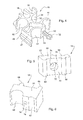
- Fig. 1
- is an exploded perspective view showing a clamp assembly according to the present invention,
- Fig. 2
- is a perspective view of the clamp assembly according to
Fig. 1 , - Fig. 3
- is a detailed exploded perspective view of the clamp assembly according to
Fig. 2 , - Fig. 4
- is a perspective view of an inner clamp member of the clamp assembly accord- ing to
Fig. 2 , - Figs. 5
- is a first perspective view of an outer clamp member of the clamp assembly according to
Fig. 2 , - Fig. 6
- is a second perspective view of an outer clamp member of the clamp assembly of
Fig. 2 , and - Fig. 7
- is a top end view of the clamp assembly according to
Fig. 1 , with a portion sec- tioned for clarity. - Referring to
Fig. 1 , a plurality of clamp assemblies 10 hold elongated parts likerigid lines flexible hoses 4 and 5 to aframe member 6 of a vehicle, such as a cab post of an agricultural tractor. As best seen inFigs. 2 and3 , eachclamp assembly 10 includes a box-shaped housing 11 having aninner housing 12 and anouter housing 14, both with C, J or U-shaped cross sections. Theinner housing 12 and theouter housing 14 enclose an innerhalf clamp member 16 and an outerhalf clamp member 18.Inner housing 12 includes abase wall 20 and a pair ofside walls Outer housing 14 includes abase wall 26 and a pair ofside walls inner housing 12 and theouter housing 14 are preferably bolted together by screws. - Referring now to
Fig. 4 , innerhalf clamp member 16 is preferably made of a rigid (plastic) material and includes abody 32 in which is formed a plurality ofinner grooves outer grooves elongated guide member 46 projects from aside 47 of thebody 32 and is slidably received by acomplimentary slot 48 formed in theside wall 22 ofinner housing 12 as shown inFig. 3 . Apost 50 with a prongedend 52 projects fromsurface 54 and away frominner groove 38. - Referring now to
Figs. 5 and 6 , outerhalf clamp member 18 is preferably made of a flexible or resilient material and includes abody 60 in which is formed a pair ofinner recesses rigid lines apart ridges outer surface 70 ofbody 60. Alarger diameter bore 72 extends partway into thebody 60 fromouter surface 70 and communicates with asmaller diameter bore 74 which extends partway intobody 60 frominner surface 76. Bores 72 and 74 are separated byannular wall 78. - Referring now to
Fig. 7 , when theclamp assembly 10 is assembled, inner elongated parts formed byflexible hoses 4 and 5 are inserted intoinner grooves half clamp member 16, and this arrangement is then slid intoinner housing 12 withelongated guide member 46 being received byslot 48 as shown inFig. 3 . Then outer elongated parts formed byrigid lines outer grooves half clamp member 18 is oriented and moved towards innerhalf clamp member 16 untilpost 50 moves through smaller diameter bore 74 and prongedend 52 moves past and engagesannular wall 78 oflarger diameter bore 72. Thus,rigid lines half clamp member 16 and outerhalf clamp member 18. Finallyouter housing 14 is attached as a cover toinner housing 12 so that resilient outerhalf clamp member 18 is compressed between the innerhalf clamp member 16 andouter housing 14. - The
post 50 may be used to temporarily attach innerhalf clamp member 16 to outerhalf clamp member 18, and to thereby hold both the outerhalf clamp member 18 as well as therigid lines outer housing 14 is assembled. When theouter housing 14 is attached in place, the resilient outerhalf clamp member 18 is compressed which holds the innerhalf clamp member 16, therigid lines flexible hoses 4 and 5 in place in a minimum amount of space. - With this design, the lines, hoses and harnesses can actually be routed in the space available while providing a consistent path for these components that deters abrasion. The
elongated guide member 46 of innerhalf clamp member 16 slides intoslot 48 in theinner housing 12 so that no additional fasteners are required to hold the innerhalf clamp member 16 during assembly. The resilient outerhalf clamp member 18 not only compresses to hold the lines, hoses and harnesses but, being a flexible or resilient material it can accommodate some variation in, or size of, the box-shaped housing 11 in which the lines, hoses and harnesses are routed. - The
clamp assembly 10 can be used on many types of vehicles. It can be used in an agricultural tractor which has a structural cab frame (ROPS) to protect the operator. The lines, hoses and harnesses may be concealed behind a finish cover which is mounted to the outside of the frame.
Claims (6)
- A clamp assembly for holding elongated parts, comprising an inner housing (12); an outer housing (14) for attaching to the inner housing (12); an inner half clamp member (16) received by the inner housing (12), the inner half clamp member (16) having an inner groove (34, 36, 38, 40) receiving an inner elongated part (4, 5), and having an outer groove (42, 44) receiving an outer elongated part (2, 3); and an outer half clamp member (18), the outer half clamp member (18) being comprised of a resilient material, the outer half clamp member (18) being compressed between the outer housing (14) and the inner half clamp member (16), and the outer elongated part (2, 3) being held between the inner half clamp member (16) and the outer half clamp member (18).
- The clamp assembly according to claim 1, characterized in that the inner half clamp member (16) includes an elongated guide member (46) which is received by a slot (48) formed in the inner housing (12).
- The clamp assembly according to claim 1 or 2, characterized in that the inner half clamp member (16) includes a post (50) which projects therefrom, and the outer half clamp member (18) includes a bore (72, 74) which receives the post (50).
- The clamp assembly according to one of claims 1 to 3, characterized in that the post (50) has a pronged end (52) which engages an annular wall (78) of the outer half clamp member (18).
- The clamp assembly according to one of claims 1 to 4, characterized in that the inner half clamp member (16) is formed out of a rigid material, and the outer half clamp member (18) is formed out of a resilient material.
- The clamp assembly according to one of claims 1 to 5, characterized in that the inner and outer housings (12, 14) enclose the inner and outer half clamp members (16, 18) and the inner and outer elongated parts (2, 3, 4, 5).
Applications Claiming Priority (1)
| Application Number | Priority Date | Filing Date | Title |
|---|---|---|---|
| US12/428,122 US8291551B2 (en) | 2009-04-22 | 2009-04-22 | Clamp assembly |
Publications (3)
| Publication Number | Publication Date |
|---|---|
| EP2243967A2 true EP2243967A2 (en) | 2010-10-27 |
| EP2243967A3 EP2243967A3 (en) | 2014-01-15 |
| EP2243967B1 EP2243967B1 (en) | 2017-01-25 |
Family
ID=42355328
Family Applications (1)
| Application Number | Title | Priority Date | Filing Date |
|---|---|---|---|
| EP10159484.4A Not-in-force EP2243967B1 (en) | 2009-04-22 | 2010-04-09 | Clamp assembly for holding elongated parts |
Country Status (2)
| Country | Link |
|---|---|
| US (1) | US8291551B2 (en) |
| EP (1) | EP2243967B1 (en) |
Families Citing this family (10)
| Publication number | Priority date | Publication date | Assignee | Title |
|---|---|---|---|---|
| DE102009019337B4 (en) * | 2009-04-30 | 2015-05-13 | Airbus Operations Gmbh | Modular holding device for mounted within an aircraft fuselage attachments |
| JP5084816B2 (en) * | 2009-12-02 | 2012-11-28 | 三菱電機株式会社 | Air conditioner internal / external communication line fixing structure |
| DE102010021835B4 (en) * | 2010-05-28 | 2019-05-16 | Airbus Operations Gmbh | Cable holding device for bundle laying of cables, in particular coaxial cables, in an aircraft |
| JP5440473B2 (en) * | 2010-10-22 | 2014-03-12 | 住友電装株式会社 | Wire harness exterior structure |
| FR2988155B1 (en) * | 2012-03-15 | 2015-01-16 | Airbus Operations Sas | DEVICE FOR FIXING AN ELECTRIC HARNESS IN AN AIRCRAFT |
| JP5948653B2 (en) * | 2012-05-29 | 2016-07-06 | 矢崎総業株式会社 | Wire harness wiring structure |
| JP2014044890A (en) * | 2012-08-28 | 2014-03-13 | Sumitomo Wiring Syst Ltd | Holding structure of optional connector |
| CA2913144A1 (en) * | 2013-05-30 | 2014-12-04 | Volvo Construction Equipment Ab | Pipe fixing device for construction machine |
| US9788477B2 (en) | 2015-06-30 | 2017-10-17 | Cnh Industrial America Llc | Mounting system for row unit options for a planter |
| US11319808B2 (en) * | 2018-10-12 | 2022-05-03 | Caterpillar Global Mining Equipment Llc | Hose retention system for drilling machine |
Family Cites Families (13)
| Publication number | Priority date | Publication date | Assignee | Title |
|---|---|---|---|---|
| JPS5141226Y2 (en) * | 1972-04-22 | 1976-10-07 | ||
| FR2280013A1 (en) * | 1975-03-24 | 1976-02-20 | Poclain Sa | Support device for pipes - has collar around half discs with recesses holding pipes |
| DE3602625C1 (en) * | 1986-01-29 | 1987-03-05 | Bayerische Motoren Werke Ag | Holding device for at least one line, in particular a fuel line on a motor vehicle |
| DE4039822C1 (en) * | 1990-12-13 | 1992-07-23 | A. Raymond Kg, 7850 Loerrach, De | |
| US5794897A (en) * | 1996-04-22 | 1998-08-18 | Andrew Corporation | Transmission line hanger, a method of attaching the hanger and the resulting assembly |
| US5742982A (en) * | 1996-11-25 | 1998-04-28 | Siecor Corporation | Cable strain relief apparatus |
| JP4092086B2 (en) * | 2000-06-30 | 2008-05-28 | 矢崎総業株式会社 | Corrugated tube fixture |
| NL1016703C2 (en) * | 2000-11-24 | 2002-05-27 | Beele Eng Bv | Feeding device. |
| JP3741999B2 (en) * | 2001-11-14 | 2006-02-01 | 矢崎総業株式会社 | Corrugated tube rotation holder |
| JP2003214559A (en) * | 2002-01-22 | 2003-07-30 | Nifco Inc | Clamp and fixing method of tubular material |
| US6561466B1 (en) * | 2002-02-20 | 2003-05-13 | Mitchell W. Myers | Interchangeable hose, cable, and conduit support mechanism |
| JP3940308B2 (en) * | 2002-03-27 | 2007-07-04 | 矢崎総業株式会社 | Harness fixture |
| US7534965B1 (en) * | 2008-01-29 | 2009-05-19 | Thompson David M | Cable grommet with ball and socket |
-
2009
- 2009-04-22 US US12/428,122 patent/US8291551B2/en not_active Expired - Fee Related
-
2010
- 2010-04-09 EP EP10159484.4A patent/EP2243967B1/en not_active Not-in-force
Non-Patent Citations (1)
| Title |
|---|
| None |
Also Published As
| Publication number | Publication date |
|---|---|
| US20100269313A1 (en) | 2010-10-28 |
| EP2243967A3 (en) | 2014-01-15 |
| EP2243967B1 (en) | 2017-01-25 |
| US8291551B2 (en) | 2012-10-23 |
Similar Documents
| Publication | Publication Date | Title |
|---|---|---|
| EP2243967B1 (en) | Clamp assembly for holding elongated parts | |
| USD1067122S1 (en) | Automobile | |
| USD539194S1 (en) | Automobile grille | |
| ITRM20000002A0 (en) | STORAGE ROOM FOR MOTOR VEHICLE DASHBOARD. | |
| EP1257045A3 (en) | Stage system with onboard linear motor | |
| PL364424A1 (en) | Motor vehicle equipment module | |
| KR20160083076A (en) | Slide seat wire harness routing device | |
| DE60205562D1 (en) | Directionless squib connector for automotive airbag systems | |
| JP2015110424A (en) | Wire harness wiring structure | |
| GB2382730B (en) | Wire harness and vehicle module assembly incorporating the same | |
| DE60005737D1 (en) | Bumper assembly for vehicles | |
| PL1890929T3 (en) | Method for assembling components of a vehicle body | |
| JP2012051494A (en) | Wire harness laying structure | |
| AU6421000A (en) | Clip assembly for an automotive vehicle | |
| GB2384217B (en) | An vehicle bumper assembly | |
| WO2008122736A3 (en) | Arrangement for attaching a fender on the bodywork structure of a vehicle | |
| ATE442977T1 (en) | DEVICE WITH ADJUSTABLE LENGTH FOR LUGGAGE STORAGE FOR A MOTOR VEHICLE TRUNK COMPARTMENT AND MOTOR VEHICLE EQUIPPED THEREFROM | |
| US6642454B2 (en) | Electrical wiring harness guiding and retaining device | |
| EP1733954A3 (en) | Under-cover mounting structure for an industrial vehicle | |
| JP2003118506A (en) | Connection structure between instrument panel connector and body side connector | |
| EP2939883A1 (en) | Fixing and sealing system for door connector | |
| ATE442979T1 (en) | BUMPER FOR MOTOR VEHICLE | |
| FR2836877B1 (en) | MODULAR PARTITION FOR INTERIOR SPACE, ESPECIALLY A MOTOR VEHICLE | |
| NL1008157A1 (en) | Clamp for a seismic cable module. | |
| USD543135S1 (en) | Automotive vehicle and/or toy replica thereof |
Legal Events
| Date | Code | Title | Description |
|---|---|---|---|
| PUAI | Public reference made under article 153(3) epc to a published international application that has entered the european phase |
Free format text: ORIGINAL CODE: 0009012 |
|
| AK | Designated contracting states |
Kind code of ref document: A2 Designated state(s): AT BE BG CH CY CZ DE DK EE ES FI FR GB GR HR HU IE IS IT LI LT LU LV MC MK MT NL NO PL PT RO SE SI SK SM TR |
|
| AX | Request for extension of the european patent |
Extension state: AL BA ME RS |
|
| PUAL | Search report despatched |
Free format text: ORIGINAL CODE: 0009013 |
|
| AK | Designated contracting states |
Kind code of ref document: A3 Designated state(s): AT BE BG CH CY CZ DE DK EE ES FI FR GB GR HR HU IE IS IT LI LT LU LV MC MK MT NL NO PL PT RO SE SI SK SM TR |
|
| AX | Request for extension of the european patent |
Extension state: AL BA ME RS |
|
| RIC1 | Information provided on ipc code assigned before grant |
Ipc: F16B 7/04 20060101AFI20131209BHEP |
|
| 17P | Request for examination filed |
Effective date: 20140715 |
|
| RBV | Designated contracting states (corrected) |
Designated state(s): AT BE BG CH CY CZ DE DK EE ES FI FR GB GR HR HU IE IS IT LI LT LU LV MC MK MT NL NO PL PT RO SE SI SK SM TR |
|
| 17Q | First examination report despatched |
Effective date: 20151217 |
|
| GRAP | Despatch of communication of intention to grant a patent |
Free format text: ORIGINAL CODE: EPIDOSNIGR1 |
|
| INTG | Intention to grant announced |
Effective date: 20160826 |
|
| GRAS | Grant fee paid |
Free format text: ORIGINAL CODE: EPIDOSNIGR3 |
|
| GRAA | (expected) grant |
Free format text: ORIGINAL CODE: 0009210 |
|
| AK | Designated contracting states |
Kind code of ref document: B1 Designated state(s): AT BE BG CH CY CZ DE DK EE ES FI FR GB GR HR HU IE IS IT LI LT LU LV MC MK MT NL NO PL PT RO SE SI SK SM TR |
|
| REG | Reference to a national code |
Ref country code: GB Ref legal event code: FG4D |
|
| REG | Reference to a national code |
Ref country code: CH Ref legal event code: EP |
|
| REG | Reference to a national code |
Ref country code: AT Ref legal event code: REF Ref document number: 864331 Country of ref document: AT Kind code of ref document: T Effective date: 20170215 |
|
| REG | Reference to a national code |
Ref country code: IE Ref legal event code: FG4D |
|
| REG | Reference to a national code |
Ref country code: DE Ref legal event code: R096 Ref document number: 602010039748 Country of ref document: DE |
|
| REG | Reference to a national code |
Ref country code: LT Ref legal event code: MG4D |
|
| REG | Reference to a national code |
Ref country code: NL Ref legal event code: MP Effective date: 20170125 |
|
| REG | Reference to a national code |
Ref country code: AT Ref legal event code: MK05 Ref document number: 864331 Country of ref document: AT Kind code of ref document: T Effective date: 20170125 |
|
| PG25 | Lapsed in a contracting state [announced via postgrant information from national office to epo] |
Ref country code: NL Free format text: LAPSE BECAUSE OF FAILURE TO SUBMIT A TRANSLATION OF THE DESCRIPTION OR TO PAY THE FEE WITHIN THE PRESCRIBED TIME-LIMIT Effective date: 20170125 |
|
| PG25 | Lapsed in a contracting state [announced via postgrant information from national office to epo] |
Ref country code: HR Free format text: LAPSE BECAUSE OF FAILURE TO SUBMIT A TRANSLATION OF THE DESCRIPTION OR TO PAY THE FEE WITHIN THE PRESCRIBED TIME-LIMIT Effective date: 20170125 Ref country code: IS Free format text: LAPSE BECAUSE OF FAILURE TO SUBMIT A TRANSLATION OF THE DESCRIPTION OR TO PAY THE FEE WITHIN THE PRESCRIBED TIME-LIMIT Effective date: 20170525 Ref country code: NO Free format text: LAPSE BECAUSE OF FAILURE TO SUBMIT A TRANSLATION OF THE DESCRIPTION OR TO PAY THE FEE WITHIN THE PRESCRIBED TIME-LIMIT Effective date: 20170425 Ref country code: FI Free format text: LAPSE BECAUSE OF FAILURE TO SUBMIT A TRANSLATION OF THE DESCRIPTION OR TO PAY THE FEE WITHIN THE PRESCRIBED TIME-LIMIT Effective date: 20170125 Ref country code: GR Free format text: LAPSE BECAUSE OF FAILURE TO SUBMIT A TRANSLATION OF THE DESCRIPTION OR TO PAY THE FEE WITHIN THE PRESCRIBED TIME-LIMIT Effective date: 20170426 Ref country code: LT Free format text: LAPSE BECAUSE OF FAILURE TO SUBMIT A TRANSLATION OF THE DESCRIPTION OR TO PAY THE FEE WITHIN THE PRESCRIBED TIME-LIMIT Effective date: 20170125 |
|
| PG25 | Lapsed in a contracting state [announced via postgrant information from national office to epo] |
Ref country code: PT Free format text: LAPSE BECAUSE OF FAILURE TO SUBMIT A TRANSLATION OF THE DESCRIPTION OR TO PAY THE FEE WITHIN THE PRESCRIBED TIME-LIMIT Effective date: 20170525 Ref country code: ES Free format text: LAPSE BECAUSE OF FAILURE TO SUBMIT A TRANSLATION OF THE DESCRIPTION OR TO PAY THE FEE WITHIN THE PRESCRIBED TIME-LIMIT Effective date: 20170125 Ref country code: BG Free format text: LAPSE BECAUSE OF FAILURE TO SUBMIT A TRANSLATION OF THE DESCRIPTION OR TO PAY THE FEE WITHIN THE PRESCRIBED TIME-LIMIT Effective date: 20170425 Ref country code: SE Free format text: LAPSE BECAUSE OF FAILURE TO SUBMIT A TRANSLATION OF THE DESCRIPTION OR TO PAY THE FEE WITHIN THE PRESCRIBED TIME-LIMIT Effective date: 20170125 Ref country code: LV Free format text: LAPSE BECAUSE OF FAILURE TO SUBMIT A TRANSLATION OF THE DESCRIPTION OR TO PAY THE FEE WITHIN THE PRESCRIBED TIME-LIMIT Effective date: 20170125 Ref country code: AT Free format text: LAPSE BECAUSE OF FAILURE TO SUBMIT A TRANSLATION OF THE DESCRIPTION OR TO PAY THE FEE WITHIN THE PRESCRIBED TIME-LIMIT Effective date: 20170125 Ref country code: PL Free format text: LAPSE BECAUSE OF FAILURE TO SUBMIT A TRANSLATION OF THE DESCRIPTION OR TO PAY THE FEE WITHIN THE PRESCRIBED TIME-LIMIT Effective date: 20170125 |
|
| REG | Reference to a national code |
Ref country code: DE Ref legal event code: R097 Ref document number: 602010039748 Country of ref document: DE |
|
| PG25 | Lapsed in a contracting state [announced via postgrant information from national office to epo] |
Ref country code: IT Free format text: LAPSE BECAUSE OF FAILURE TO SUBMIT A TRANSLATION OF THE DESCRIPTION OR TO PAY THE FEE WITHIN THE PRESCRIBED TIME-LIMIT Effective date: 20170125 Ref country code: SK Free format text: LAPSE BECAUSE OF FAILURE TO SUBMIT A TRANSLATION OF THE DESCRIPTION OR TO PAY THE FEE WITHIN THE PRESCRIBED TIME-LIMIT Effective date: 20170125 Ref country code: RO Free format text: LAPSE BECAUSE OF FAILURE TO SUBMIT A TRANSLATION OF THE DESCRIPTION OR TO PAY THE FEE WITHIN THE PRESCRIBED TIME-LIMIT Effective date: 20170125 Ref country code: EE Free format text: LAPSE BECAUSE OF FAILURE TO SUBMIT A TRANSLATION OF THE DESCRIPTION OR TO PAY THE FEE WITHIN THE PRESCRIBED TIME-LIMIT Effective date: 20170125 Ref country code: CZ Free format text: LAPSE BECAUSE OF FAILURE TO SUBMIT A TRANSLATION OF THE DESCRIPTION OR TO PAY THE FEE WITHIN THE PRESCRIBED TIME-LIMIT Effective date: 20170125 |
|
| PG25 | Lapsed in a contracting state [announced via postgrant information from national office to epo] |
Ref country code: DK Free format text: LAPSE BECAUSE OF FAILURE TO SUBMIT A TRANSLATION OF THE DESCRIPTION OR TO PAY THE FEE WITHIN THE PRESCRIBED TIME-LIMIT Effective date: 20170125 Ref country code: SM Free format text: LAPSE BECAUSE OF FAILURE TO SUBMIT A TRANSLATION OF THE DESCRIPTION OR TO PAY THE FEE WITHIN THE PRESCRIBED TIME-LIMIT Effective date: 20170125 |
|
| REG | Reference to a national code |
Ref country code: CH Ref legal event code: PL |
|
| PLBE | No opposition filed within time limit |
Free format text: ORIGINAL CODE: 0009261 |
|
| STAA | Information on the status of an ep patent application or granted ep patent |
Free format text: STATUS: NO OPPOSITION FILED WITHIN TIME LIMIT |
|
| GBPC | Gb: european patent ceased through non-payment of renewal fee |
Effective date: 20170425 |
|
| 26N | No opposition filed |
Effective date: 20171026 |
|
| REG | Reference to a national code |
Ref country code: IE Ref legal event code: MM4A |
|
| REG | Reference to a national code |
Ref country code: FR Ref legal event code: ST Effective date: 20171229 |
|
| PG25 | Lapsed in a contracting state [announced via postgrant information from national office to epo] |
Ref country code: MC Free format text: LAPSE BECAUSE OF FAILURE TO SUBMIT A TRANSLATION OF THE DESCRIPTION OR TO PAY THE FEE WITHIN THE PRESCRIBED TIME-LIMIT Effective date: 20170125 Ref country code: FR Free format text: LAPSE BECAUSE OF NON-PAYMENT OF DUE FEES Effective date: 20170502 |
|
| PG25 | Lapsed in a contracting state [announced via postgrant information from national office to epo] |
Ref country code: SI Free format text: LAPSE BECAUSE OF FAILURE TO SUBMIT A TRANSLATION OF THE DESCRIPTION OR TO PAY THE FEE WITHIN THE PRESCRIBED TIME-LIMIT Effective date: 20170125 Ref country code: LI Free format text: LAPSE BECAUSE OF NON-PAYMENT OF DUE FEES Effective date: 20170430 Ref country code: LU Free format text: LAPSE BECAUSE OF NON-PAYMENT OF DUE FEES Effective date: 20170409 Ref country code: GB Free format text: LAPSE BECAUSE OF NON-PAYMENT OF DUE FEES Effective date: 20170425 Ref country code: CH Free format text: LAPSE BECAUSE OF NON-PAYMENT OF DUE FEES Effective date: 20170430 |
|
| REG | Reference to a national code |
Ref country code: BE Ref legal event code: MM Effective date: 20170430 |
|
| PG25 | Lapsed in a contracting state [announced via postgrant information from national office to epo] |
Ref country code: IE Free format text: LAPSE BECAUSE OF NON-PAYMENT OF DUE FEES Effective date: 20170409 |
|
| PG25 | Lapsed in a contracting state [announced via postgrant information from national office to epo] |
Ref country code: BE Free format text: LAPSE BECAUSE OF NON-PAYMENT OF DUE FEES Effective date: 20170430 |
|
| PG25 | Lapsed in a contracting state [announced via postgrant information from national office to epo] |
Ref country code: MT Free format text: LAPSE BECAUSE OF NON-PAYMENT OF DUE FEES Effective date: 20170409 |
|
| PG25 | Lapsed in a contracting state [announced via postgrant information from national office to epo] |
Ref country code: HU Free format text: LAPSE BECAUSE OF FAILURE TO SUBMIT A TRANSLATION OF THE DESCRIPTION OR TO PAY THE FEE WITHIN THE PRESCRIBED TIME-LIMIT; INVALID AB INITIO Effective date: 20100409 |
|
| PG25 | Lapsed in a contracting state [announced via postgrant information from national office to epo] |
Ref country code: CY Free format text: LAPSE BECAUSE OF NON-PAYMENT OF DUE FEES Effective date: 20170125 |
|
| PG25 | Lapsed in a contracting state [announced via postgrant information from national office to epo] |
Ref country code: MK Free format text: LAPSE BECAUSE OF FAILURE TO SUBMIT A TRANSLATION OF THE DESCRIPTION OR TO PAY THE FEE WITHIN THE PRESCRIBED TIME-LIMIT Effective date: 20170125 |
|
| PG25 | Lapsed in a contracting state [announced via postgrant information from national office to epo] |
Ref country code: TR Free format text: LAPSE BECAUSE OF FAILURE TO SUBMIT A TRANSLATION OF THE DESCRIPTION OR TO PAY THE FEE WITHIN THE PRESCRIBED TIME-LIMIT Effective date: 20170125 |
|
| PGFP | Annual fee paid to national office [announced via postgrant information from national office to epo] |
Ref country code: DE Payment date: 20230321 Year of fee payment: 14 |
|
| REG | Reference to a national code |
Ref country code: DE Ref legal event code: R119 Ref document number: 602010039748 Country of ref document: DE |
|
| PG25 | Lapsed in a contracting state [announced via postgrant information from national office to epo] |
Ref country code: DE Free format text: LAPSE BECAUSE OF NON-PAYMENT OF DUE FEES Effective date: 20241105 |
|
| PG25 | Lapsed in a contracting state [announced via postgrant information from national office to epo] |
Ref country code: DE Free format text: LAPSE BECAUSE OF NON-PAYMENT OF DUE FEES Effective date: 20241105 |