EP2243965A2 - Oscillatory actuator for concrete pumps, with hydraulically driven rack and pinion unit - Google Patents
Oscillatory actuator for concrete pumps, with hydraulically driven rack and pinion unit Download PDFInfo
- Publication number
- EP2243965A2 EP2243965A2 EP10160544A EP10160544A EP2243965A2 EP 2243965 A2 EP2243965 A2 EP 2243965A2 EP 10160544 A EP10160544 A EP 10160544A EP 10160544 A EP10160544 A EP 10160544A EP 2243965 A2 EP2243965 A2 EP 2243965A2
- Authority
- EP
- European Patent Office
- Prior art keywords
- box
- rack
- gasket
- way
- sealed
- Prior art date
- Legal status (The legal status is an assumption and is not a legal conclusion. Google has not performed a legal analysis and makes no representation as to the accuracy of the status listed.)
- Granted
Links
Images
Classifications
-
- F—MECHANICAL ENGINEERING; LIGHTING; HEATING; WEAPONS; BLASTING
- F15—FLUID-PRESSURE ACTUATORS; HYDRAULICS OR PNEUMATICS IN GENERAL
- F15B—SYSTEMS ACTING BY MEANS OF FLUIDS IN GENERAL; FLUID-PRESSURE ACTUATORS, e.g. SERVOMOTORS; DETAILS OF FLUID-PRESSURE SYSTEMS, NOT OTHERWISE PROVIDED FOR
- F15B15/00—Fluid-actuated devices for displacing a member from one position to another; Gearing associated therewith
- F15B15/02—Mechanical layout characterised by the means for converting the movement of the fluid-actuated element into movement of the finally-operated member
- F15B15/06—Mechanical layout characterised by the means for converting the movement of the fluid-actuated element into movement of the finally-operated member for mechanically converting rectilinear movement into non- rectilinear movement
- F15B15/065—Mechanical layout characterised by the means for converting the movement of the fluid-actuated element into movement of the finally-operated member for mechanically converting rectilinear movement into non- rectilinear movement the motor being of the rack-and-pinion type
Definitions
- the invention relates to apparatus for pumping concrete, mortar or other liquid products, which may be dense or incoherent, over a distance, the apparatus comprising a hopper into which the concrete for pumping is placed, the hopper containing in its lower part a gooseneck pipe, one end of which is connected to the concrete removal pipe and made to rotate in an alternating way by an external oscillatory actuator, while the other end oscillates in a pendulum-like way and alternately contacts two apertures to which corresponding reciprocating single-acting pump units, driven by corresponding hydraulic actuators, are permanently connected.
- the other pump unit is in the phase in which the concrete drawn in previously is discharged through said gooseneck pipe which is in contact with it.
- An actuator of this type comprises a rack which is driven at its ends by hydraulic cylinder and piston units and which engages with a ring gear fixed on one of the two ends of the oscillation shaft of said gooseneck pipe.
- the gear is housed in an oil bath in a box-like body in which are formed the opposing chambers in which the end pistons of the rack slide in a sealed way, with attached hydraulic dampers for limiting the stroke.
- the projection of these chambers is limited, and the box-like body which contains them is provided with external cooling fins at the positions of the chambers.
- the actuator comprises a box-like body 1 formed from a single piece made by casting a suitable metal alloy in a mould with a core box, or by any other suitable method.
- the body 1 takes the form of an octagon elongated on the horizontal plane, with a curved and upwardly convex upper side 101 and with symmetrical horizontal parallelepipedal extensions 201, 201' at the opposite ends.
- Wear liners 5, 5' are inserted with a lateral seal by means of gaskets 4, 4' into the tubes 2, 2' with a high degree of precision, each liner being provided on its outer end with a small outer collar 105, 105' which is housed in a corresponding recess of the flange 102, 102', the cylindrical projection 107, 107' of a cap 7, 7' being inserted into each liner in a sealed way by means of the gaskets 6, 6', each cap also having a square base and being provided in its corner areas with through holes of stepped section to allow the passage of the shanks of screws which are indicated schematically by 8, 8' and to contain the heads of these screws, which fix the parts 2, 7 and 2', 7' to the extensions 201, 201' of the body 1 with the interposition of the corresponding wear liners 5, 5'.
- the end pistons 110, 110' of the rack 10 slide with a lateral seal, provided by means of the gaskets 9, 9', in these liners, the rack having an exposed portion, between the guide parts 2, 5 and 2', 5', which interacts with a ring gear 11 which is described more fully below.
- the shanks 207, 207' are axially hollow and have threaded holes 12, 12' opening on the caps 7, 7', to which it is possible to connect the pipes of the hydraulic circuit for driving the actuator, these pipes having alternating delivery and discharge functions, to provide the desired reciprocating motion of the rack 10.
- the body 1 has, below the rack and the guide parts for the corresponding pistons, a wide bowl-shaped chamber 13, which can contain a large quantity of oil and whose base wall 301 is suitably distant from said rack, in such a way that any impurities due to the wear of the parts are collected on this base wall in a position remote from the moving parts, with the consequent advantages.
- the wall 301 is provided with a hole with a sealing plug 14, which can be removed in order to discharge all the oil contained in the body 1, together with the impurities, for the periodic replacement of the internal lubricating oil of the actuator, the level of the oil being subsequently restored through feed, overflow and/or inspection holes 15, 15' provided in the body 1 at a level above the tubes 2, 2'.
- the box-like body 1 is provided externally, in its upper part, with two symmetrical lateral appendages 401, 401' with holes 16, 16' for the passage of corresponding fixing screws, while in its lower part the body 1 has inner parts 501, 501' of increased thickness in which through holes 17, 17' are formed, these holes also being adapted for the passage of fixing screws.
- the outer front surface of the body 1 is provided with suitable heat exchange fins 18, as shown in part in Figure 2 , to improve the dissipation of the heat produced by the reciprocating movement of the rack and by its interaction with the ring gear 11.
- the box-like body 1 is provided on opposite faces with apertures 601, 601' which are machined on their inner diameters in such a way that they are aligned axially with each other and which contain low friction rings 19, 19' which are in close contact with them, the rings being made, for example, from suitable plastic material or appropriate sintered material and being capable of supporting rotatably the end portions of a steel sleeve 111, which carries the ring gear 11 which is made in one piece with it or is fitted on it, and whose ends project from the body 1 in the form of a rear portion 211, having an outer gasket 20 for connection to the tubing for removing the pumped concrete, and a front portion 311 1 which can be fixed, with the interposition of a sealing gasket 22, to a sleeve 21 whose other end is adapted to be fixed and connected in a sealed way by means of a gasket 23 to the end of the gooseneck pipe CC which is to be made to oscillate by the actuator in question within the
- the aforesaid support rings 19, 19' are provided, on their inner surfaces in contact with the sleeve 111, with lubrication grooves which allow a sufficient degree of outward permeation of some of the lubricating oil which is contained in the body 1, for which reason suitable means are provided outside the apertures 601, 601' of the body 1 to prevent leaks of said lubricating oil.
- the rear aperture 601 is provided with a projecting collar 701 which forms an inner annular chamber 24 in which is inserted an internal gasket of metal and rubber which comprises a metal ring 25 for contacting the ring 19 and a part 125 made from elastomeric material, with a C-shaped profile and an internal spring, which interacts with the outer lateral surface of the portion 211 of the aperture 111 to form a lateral seal.
- a projecting collar 701 which forms an inner annular chamber 24 in which is inserted an internal gasket of metal and rubber which comprises a metal ring 25 for contacting the ring 19 and a part 125 made from elastomeric material, with a C-shaped profile and an internal spring, which interacts with the outer lateral surface of the portion 211 of the aperture 111 to form a lateral seal.
- annular cap 27 is then mounted on said collar 701 in a sealed way by means of the gasket 26, this cap interacting in a sealed way with the portion 211 of the aperture 111 by means of a gasket 126 on its inner diameter, and being provided externally with a pair of diametrically opposite lugs 127 which can be fixed with screws 28 to corresponding outer thickened areas 801 of the body 1.
- the front aperture 601' is machined on its outer diameter in such a way that it has a collar 901 which is mounted, with a sealing gasket 29, in a hole 30 formed in the rear plate P of the hopper T, and which terminates in said hopper with a portion 130 of smaller diameter, to retain in said hole 30 a composite metal and rubber gasket, with an outer ring 31 made from metal and with an inner annular insert 131 made from a suitable elastomeric material, with interacts in a sealed way with the outer lateral surface of the sleeves 111 and 21.
- the metal ring 31 is provided with a plurality of radial holes 32 which communicate with both inner and outer annular manifolds, indicated by 132, the outer of which communicates with a pipe 33 formed in the plate P and leading to a connector 34 which is connected to a source of pressurized air (not shown) to pressurize the rubber part 131 of the gasket in a centripetal way, in order to maintain the best possible contact of the gasket with the sleeves 111, 21, and in order to prevent the ingress of liquid and dirt into the box-like body 1 if this gasket becomes worn.
- a flowmeter or any suitable means or sensor for indicating an anomalous flow of air towards the sealing gasket 31, 131 can be connected to the connector 34, to provide a warning when this gasket needs to be replaced.
- the actuator described herein is highly reliable, is easy to construct and to maintain by both routine and extraordinary procedures, and has a long service life, in part due to the fact that the actuator can be completely restored and returned to its best operating condition by periodically changing the wear liners 5, 5' and the piston rings and sealing gaskets 9, 9' of the pistons 110, 110' of the rack, and by periodically changing the phase of the ring gear 11 with respect to the rack 10.
Landscapes
- Engineering & Computer Science (AREA)
- Physics & Mathematics (AREA)
- Fluid Mechanics (AREA)
- Mechanical Engineering (AREA)
- General Engineering & Computer Science (AREA)
- Transmission Devices (AREA)
- On-Site Construction Work That Accompanies The Preparation And Application Of Concrete (AREA)
- Reciprocating Pumps (AREA)
- Actuator (AREA)
Abstract
Description
- The invention relates to apparatus for pumping concrete, mortar or other liquid products, which may be dense or incoherent, over a distance, the apparatus comprising a hopper into which the concrete for pumping is placed, the hopper containing in its lower part a gooseneck pipe, one end of which is connected to the concrete removal pipe and made to rotate in an alternating way by an external oscillatory actuator, while the other end oscillates in a pendulum-like way and alternately contacts two apertures to which corresponding reciprocating single-acting pump units, driven by corresponding hydraulic actuators, are permanently connected. When one pump unit is in the phase in which it draws concrete from said hopper, with which it communicates directly, the other pump unit is in the phase in which the concrete drawn in previously is discharged through said gooseneck pipe which is in contact with it.
- There are known actuators, of the type described in Italian patent
223 832 - In these oscillatory actuators, which have the major advantage of operating safety because all the moving parts, namely the hydraulic cylinders, the rack and the pinion, are housed in the oil bath chamber, problems have been encountered due to the production costs, premature wear and deficient hydraulic sealing, and the invention is intended to overcome these by means of the solution, described in
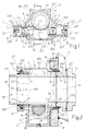
Claim 1 and the subsequent claims, which will now be illustrated in one of its preferred embodiments, with reference to the figures on the single attached sheet of drawing, of which -
Fig. 1 shows the improved actuator in question, in front elevation and in a sectional view through a theoretical vertical plane which contains the axis of the end pistons of the rack; -
Fig. 2 shows other details of the actuator in a view taken through the section line II-II ofFigure 1 . - As the drawings reveal, the actuator comprises a box-
like body 1 formed from a single piece made by casting a suitable metal alloy in a mould with a core box, or by any other suitable method. When seen from the front as inFigure 1 , thebody 1 takes the form of an octagon elongated on the horizontal plane, with a curved and upwardly convexupper side 101 and with symmetricalhorizontal parallelepipedal extensions 201, 201' at the opposite ends. These end extensions are machined internally and on their outer faces, and into these extensions there are inserted identicalrobust steel tubes 2, 2', which are axially aligned with each other, which are provided withexternal flanges 102, 102' having polygonal faces, for example square faces, and through holes in their corner areas, and which interact in a sealed way with the faces of saidextensions 201, 201' by means ofgaskets 3, 3'.Wear liners 5, 5' are inserted with a lateral seal by means of gaskets 4, 4' into thetubes 2, 2' with a high degree of precision, each liner being provided on its outer end with a smallouter collar 105, 105' which is housed in a corresponding recess of theflange 102, 102', thecylindrical projection 107, 107' of acap 7, 7' being inserted into each liner in a sealed way by means of thegaskets 6, 6', each cap also having a square base and being provided in its corner areas with through holes of stepped section to allow the passage of the shanks of screws which are indicated schematically by 8, 8' and to contain the heads of these screws, which fix theparts extensions 201, 201' of thebody 1 with the interposition of thecorresponding wear liners 5, 5'. Theend pistons 110, 110' of therack 10 slide with a lateral seal, provided by means of thegaskets 9, 9', in these liners, the rack having an exposed portion, between theguide parts ring gear 11 which is described more fully below. On the inner faces of thecaps 7, 7' there are providedcylindrical shanks 207, 207' which are made in one piece with the caps and which, as therack 10 reaches the alternating ends of its stroke, enter, with a precise clearance, correspondingaxial recesses 11, 11' of thepistons 110, 110', to provide suitable damping of the end of the stroke of the rack, in a way which is known in the art. Theshanks 207, 207' are axially hollow and have threadedholes 12, 12' opening on thecaps 7, 7', to which it is possible to connect the pipes of the hydraulic circuit for driving the actuator, these pipes having alternating delivery and discharge functions, to provide the desired reciprocating motion of therack 10. As the drawings reveal, thebody 1 has, below the rack and the guide parts for the corresponding pistons, a wide bowl-shaped chamber 13, which can contain a large quantity of oil and whosebase wall 301 is suitably distant from said rack, in such a way that any impurities due to the wear of the parts are collected on this base wall in a position remote from the moving parts, with the consequent advantages. Thewall 301 is provided with a hole with asealing plug 14, which can be removed in order to discharge all the oil contained in thebody 1, together with the impurities, for the periodic replacement of the internal lubricating oil of the actuator, the level of the oil being subsequently restored through feed, overflow and/orinspection holes 15, 15' provided in thebody 1 at a level above thetubes 2, 2'. - In order to fix the actuator described herein to the wall P of the hopper T, in which said gooseneck pipe CC is located (
Fig. 2 ), the box-like body 1 is provided externally, in its upper part, with two symmetricallateral appendages 401, 401' withholes 16, 16' for the passage of corresponding fixing screws, while in its lower part thebody 1 hasinner parts 501, 501' of increased thickness in which through holes 17, 17' are formed, these holes also being adapted for the passage of fixing screws. The outer front surface of thebody 1 is provided with suitableheat exchange fins 18, as shown in part inFigure 2 , to improve the dissipation of the heat produced by the reciprocating movement of the rack and by its interaction with thering gear 11. - As shown in
Figure 2 , the box-like body 1 is provided on opposite faces withapertures 601, 601' which are machined on their inner diameters in such a way that they are aligned axially with each other and which containlow friction rings 19, 19' which are in close contact with them, the rings being made, for example, from suitable plastic material or appropriate sintered material and being capable of supporting rotatably the end portions of asteel sleeve 111, which carries thering gear 11 which is made in one piece with it or is fitted on it, and whose ends project from thebody 1 in the form of arear portion 211, having anouter gasket 20 for connection to the tubing for removing the pumped concrete, and afront portion 311 1 which can be fixed, with the interposition of a sealinggasket 22, to asleeve 21 whose other end is adapted to be fixed and connected in a sealed way by means of agasket 23 to the end of the gooseneck pipe CC which is to be made to oscillate by the actuator in question within the hopper T, as stated in the introduction to this description. Theaforesaid support rings 19, 19' are provided, on their inner surfaces in contact with thesleeve 111, with lubrication grooves which allow a sufficient degree of outward permeation of some of the lubricating oil which is contained in thebody 1, for which reason suitable means are provided outside theapertures 601, 601' of thebody 1 to prevent leaks of said lubricating oil. For this reason, therear aperture 601 is provided with a projectingcollar 701 which forms an innerannular chamber 24 in which is inserted an internal gasket of metal and rubber which comprises ametal ring 25 for contacting thering 19 and apart 125 made from elastomeric material, with a C-shaped profile and an internal spring, which interacts with the outer lateral surface of theportion 211 of theaperture 111 to form a lateral seal. Anannular cap 27 is then mounted on saidcollar 701 in a sealed way by means of thegasket 26, this cap interacting in a sealed way with theportion 211 of theaperture 111 by means of agasket 126 on its inner diameter, and being provided externally with a pair of diametricallyopposite lugs 127 which can be fixed withscrews 28 to corresponding outer thickenedareas 801 of thebody 1. - On the other face, it can be seen that the front aperture 601' is machined on its outer diameter in such a way that it has a
collar 901 which is mounted, with a sealinggasket 29, in a hole 30 formed in the rear plate P of the hopper T, and which terminates in said hopper with aportion 130 of smaller diameter, to retain in said hole 30 a composite metal and rubber gasket, with anouter ring 31 made from metal and with an innerannular insert 131 made from a suitable elastomeric material, with interacts in a sealed way with the outer lateral surface of thesleeves metal ring 31 is provided with a plurality ofradial holes 32 which communicate with both inner and outer annular manifolds, indicated by 132, the outer of which communicates with apipe 33 formed in the plate P and leading to aconnector 34 which is connected to a source of pressurized air (not shown) to pressurize therubber part 131 of the gasket in a centripetal way, in order to maintain the best possible contact of the gasket with thesleeves like body 1 if this gasket becomes worn. A flowmeter or any suitable means or sensor for indicating an anomalous flow of air towards the sealinggasket connector 34, to provide a warning when this gasket needs to be replaced. - Clearly, the actuator described herein is highly reliable, is easy to construct and to maintain by both routine and extraordinary procedures, and has a long service life, in part due to the fact that the actuator can be completely restored and returned to its best operating condition by periodically changing the
wear liners 5, 5' and the piston rings and sealinggaskets 9, 9' of thepistons 110, 110' of the rack, and by periodically changing the phase of thering gear 11 with respect to therack 10.
Claims (8)
- Oscillatory actuator for pumps for concrete or other dense or incoherent liquid products, having a pinion or ring gear unit (11) which is connected to the end of the gooseneck pipe (CC) which is to be made to rotate alternately in both directions, and which interacts with a rack (10) driven hydraulically by the alternating sliding of its end pistons (110, 110') in sealed chambers formed in a box-like body (1) which contains the rack and pinion unit, characterized in that the end pistons of the rack, with their piston rings and lateral gaskets (9, 9'), slide in wear liners (5, 5') mounted in a sealed way with corresponding gaskets (4, 4') in robust tubes (2, 2') which are fixed, with their sealing means (3, 3'), in axially aligned seats (201, 201') of said box-like body, together with the caps (7, 7') which interact in a sealed way with said liners and which have holes (12, 12') for connection to the pipes of the hydraulic drive circuit, these pipes having alternating delivery and discharge functions.
- Actuator according to Claim 1), in which said box-like body (1) is made in a single piece by casting a suitable metal alloy in a mould with a core box or by an equivalent method, in such a way that, viewed from the front, said box-like body has, for example, the shape of an octagon elongated on the horizontal plane, with a curved and outwardly convex top side (101), to form a housing capable of containing the toothed ring (11), this body having symmetrical horizontal parallelepipedal extensions (201, 201') at the opposite ends, in which are formed the seats for housing said tubes (2, 2') with the inner liners (5, 5') and with said closing caps (7, 7'), this box-like body (1) being made to have, under the rack and the parts for guiding the corresponding pistons, a wide chamber or bowl (13) which can contain a large quantity of oil which reaches the level of feed and inspection holes (15, 15') provided in the body (1) at a level above that of said tubes (2, 2'), the base wall (301) of said bowl having a discharge plug (14) and being suitably distant from said rack.
- Actuator according to the preceding claims, characterized in that, for the purpose of fixing for use, said box-like body (1) has two external lateral symmetrical appendages (401, 401') in its upper part with holes (16, 16') for the passage of corresponding fixing screws, while in its lower part the body (1) has parts of increased thickness (501, 501') in which are formed through holes (17, 17') which can also be used for the passage of fixing screws.
- Actuator according to the preceding claims, in which said box-like body (1) is provided on its opposite faces with round apertures (601, 601') which are machined in such a way that they are aligned axially with each other and house, with close contact, low friction rings (19, 19') which can rotatably support end portions of a steel sleeve (111) which carries the ring gear (11) which is made in one piece with it or is fitted on it, and whose ends project from said body to the rear, in the form of a portion (211) for connection to the tubing for removing the pumped concrete, and to the front, in the form of a portion (311) which can be fixed, with the interposition of sealing means (22), to a sleeve (21) whose other end is adapted to be fixed in a sealed way to the end of the gooseneck pipe (CC) which is to be made to oscillate by said actuator in question within the hopper (T).
- Actuator according to Claim 4), in which said support rings (19, 19') are provided, on their inner surfaces which contact the sleeve (111), with lubrication grooves which allow sufficient outward permeation of some of the lubricating oil contained in the box-like body (1), the apertures (601, 601') of this body being provided with sealing means which act on the outer lateral surface of said sleeve (111).
- Equipment according to Claim 5), in which the rear aperture (601) of the box-like body (1) is provided with a projecting collar (701) which forms an annular chamber (24) housing a sealing means (25, 125) which interacts with the outer lateral surface of the rear portion (211) of said aperture (11), an annular cap (27) being mounted externally in a sealed way on the collar (701), this cap having a seal (126) on its inner diameter which interacts with the rear portion (211) of the sleeve (111) and which is provided externally with means (127) for fixing with screws (28) to corresponding connectors (801) of the box-like body (1).
- Actuator according to Claim 5), in which the front aperture (601') of the box-like body (1) is also machined on its outer diameter in such a way that it has a collar (901) which is mounted in a sealed way in a hole (30) formed on the rear plate (P) of the hopper (T) and which terminates within the hopper in a portion (130) of smaller diameter, which retains in the hole (30) a composite gasket with an outer metal ring (31) and with an inner annular insert (131) made from a suitable elastomeric material, which interacts in a sealed way with the outer lateral surface of the apertures (111, 21) and which can be connected, through pipes (32, 132) formed in said ring (31) and with others (33, 34) formed in said plate (P), to a source of pressurized air, which pressurizes in a centripetal way the rubber part (131) of said gasket, in order to maintain the best possible contact of the gasket with the inner sleeves, and in order to prevent the ingress of liquid and dirt into the box-like body (1) if this gasket becomes worn.
- Actuator according to Claim 7), in which a flowmeter or any suitable means or sensor for indicating an anomalous flow of air towards the sealing gasket (31, 131) can be connected to the connector (34) which supplies pressurized air to said gasket, to provide a warning when this gasket needs to be replaced.
Applications Claiming Priority (1)
| Application Number | Priority Date | Filing Date | Title |
|---|---|---|---|
| ITBO20090024 ITBO20090024U1 (en) | 2009-04-22 | 2009-04-22 | OSCILLATING MOVEMENT ACTUATOR, FOR CONCRETE PUMPS, WITH PINION GROUP AND HYDRAULICLY MOVED RACK. |
Publications (3)
| Publication Number | Publication Date |
|---|---|
| EP2243965A2 true EP2243965A2 (en) | 2010-10-27 |
| EP2243965A3 EP2243965A3 (en) | 2013-10-09 |
| EP2243965B1 EP2243965B1 (en) | 2015-03-25 |
Family
ID=42357843
Family Applications (1)
| Application Number | Title | Priority Date | Filing Date |
|---|---|---|---|
| EP20100160544 Active EP2243965B1 (en) | 2009-04-22 | 2010-04-21 | Oscillatory actuator for concrete pumps, with hydraulically driven rack and pinion unit |
Country Status (2)
| Country | Link |
|---|---|
| EP (1) | EP2243965B1 (en) |
| IT (1) | ITBO20090024U1 (en) |
Cited By (1)
| Publication number | Priority date | Publication date | Assignee | Title |
|---|---|---|---|---|
| WO2013001173A1 (en) | 2011-06-27 | 2013-01-03 | Ksb S.A.S. | Quarter turn actuator having a non-cylindrical pinion, and complementary rack |
Citations (1)
| Publication number | Priority date | Publication date | Assignee | Title |
|---|---|---|---|---|
| IT223832Z2 (en) | 1990-03-30 | 1995-10-03 | OSCILLATING DISPENSER FOR CONCRETE PUMPS, OPERATED BY A HYDRAULICALLY MOVED PINION-RACK COMPLEX. |
Family Cites Families (5)
| Publication number | Priority date | Publication date | Assignee | Title |
|---|---|---|---|---|
| US3245271A (en) * | 1962-01-08 | 1966-04-12 | Central States Tooling Service | Hydraulic actuator |
| US3209541A (en) * | 1963-07-29 | 1965-10-05 | William P Dunphy | Hydraulic remote control apparatus |
| US3834284A (en) * | 1973-04-05 | 1974-09-10 | Deere & Co | Hydraulic steering for tractors and like vehicles |
| US5353690A (en) * | 1993-03-04 | 1994-10-11 | Shin Guo S | Actuator type reciprocating mechanism |
| US5323690A (en) * | 1993-03-05 | 1994-06-28 | Sims James O | Fluid actuator assembly for imparting rotational movement to a boom |
-
2009
- 2009-04-22 IT ITBO20090024 patent/ITBO20090024U1/en unknown
-
2010
- 2010-04-21 EP EP20100160544 patent/EP2243965B1/en active Active
Patent Citations (1)
| Publication number | Priority date | Publication date | Assignee | Title |
|---|---|---|---|---|
| IT223832Z2 (en) | 1990-03-30 | 1995-10-03 | OSCILLATING DISPENSER FOR CONCRETE PUMPS, OPERATED BY A HYDRAULICALLY MOVED PINION-RACK COMPLEX. |
Cited By (1)
| Publication number | Priority date | Publication date | Assignee | Title |
|---|---|---|---|---|
| WO2013001173A1 (en) | 2011-06-27 | 2013-01-03 | Ksb S.A.S. | Quarter turn actuator having a non-cylindrical pinion, and complementary rack |
Also Published As
| Publication number | Publication date |
|---|---|
| ITBO20090024U1 (en) | 2010-10-23 |
| EP2243965A3 (en) | 2013-10-09 |
| EP2243965B1 (en) | 2015-03-25 |
Similar Documents
| Publication | Publication Date | Title |
|---|---|---|
| CN209800178U (en) | reciprocating type three-cylinder plunger pump for oil and gas field | |
| JPS632034B2 (en) | ||
| JP2006145028A (en) | Automatic type lubricating device | |
| AU2010100908A4 (en) | Plunger oil free high pressure pump | |
| CN113819051B (en) | Fluid end and plunger pump | |
| US6622612B2 (en) | Pump, particularly plunger pump | |
| CN104153987A (en) | Self-sufficient type power end lubricating oil circulating cooling system | |
| GB2590546A (en) | Hydraulic piston machine | |
| EP2243965B1 (en) | Oscillatory actuator for concrete pumps, with hydraulically driven rack and pinion unit | |
| CN104696212B (en) | Crankshaft type high-pressure plunger pump adopting water lubrication | |
| EP4063653A1 (en) | High-pressure piston volumetric pump | |
| CN207777126U (en) | Compressor crankcase, compressor and refrigerator | |
| CN201047339Y (en) | Superhigh tension three vats plunger pump | |
| CN204239224U (en) | A kind of high-pressure plunger oil seal of pull rod assembly | |
| US10232432B2 (en) | Mold oscillator | |
| KR101409983B1 (en) | Automatic grease lubricator by plunger periodic motion | |
| RU2739103C1 (en) | Three-piston drilling machine of unilateral action | |
| CN102852784B (en) | Plunger pump | |
| KR20020090198A (en) | The piston's lubricating device in a piston-reciprocating high-pressure spray | |
| RU39365U1 (en) | OIL INDUSTRIAL PLUNGER PUMP | |
| EP3271585B1 (en) | Swash plate pump, designed for easy maintenance | |
| CN203476241U (en) | Polished rod lubricating and righting device of oil pumping unit | |
| RU2559679C1 (en) | Well sucker-rod pump | |
| CN211231107U (en) | Dustproof multistage telescopic hydraulic cylinder | |
| CN218062632U (en) | Ceramic pump with water seal structure |
Legal Events
| Date | Code | Title | Description |
|---|---|---|---|
| PUAI | Public reference made under article 153(3) epc to a published international application that has entered the european phase |
Free format text: ORIGINAL CODE: 0009012 |
|
| AK | Designated contracting states |
Kind code of ref document: A2 Designated state(s): AT BE BG CH CY CZ DE DK EE ES FI FR GB GR HR HU IE IS IT LI LT LU LV MC MK MT NL NO PL PT RO SE SI SK SM TR |
|
| AX | Request for extension of the european patent |
Extension state: AL BA ME RS |
|
| PUAL | Search report despatched |
Free format text: ORIGINAL CODE: 0009013 |
|
| AK | Designated contracting states |
Kind code of ref document: A3 Designated state(s): AT BE BG CH CY CZ DE DK EE ES FI FR GB GR HR HU IE IS IT LI LT LU LV MC MK MT NL NO PL PT RO SE SI SK SM TR |
|
| AX | Request for extension of the european patent |
Extension state: AL BA ME RS |
|
| RIC1 | Information provided on ipc code assigned before grant |
Ipc: F15B 15/06 20060101AFI20130903BHEP |
|
| 17P | Request for examination filed |
Effective date: 20140321 |
|
| RBV | Designated contracting states (corrected) |
Designated state(s): AT BE BG CH CY CZ DE DK EE ES FI FR GB GR HR HU IE IS IT LI LT LU LV MC MK MT NL NO PL PT RO SE SI SK SM TR |
|
| GRAP | Despatch of communication of intention to grant a patent |
Free format text: ORIGINAL CODE: EPIDOSNIGR1 |
|
| INTG | Intention to grant announced |
Effective date: 20141006 |
|
| GRAS | Grant fee paid |
Free format text: ORIGINAL CODE: EPIDOSNIGR3 |
|
| GRAA | (expected) grant |
Free format text: ORIGINAL CODE: 0009210 |
|
| AK | Designated contracting states |
Kind code of ref document: B1 Designated state(s): AT BE BG CH CY CZ DE DK EE ES FI FR GB GR HR HU IE IS IT LI LT LU LV MC MK MT NL NO PL PT RO SE SI SK SM TR |
|
| REG | Reference to a national code |
Ref country code: GB Ref legal event code: FG4D |
|
| REG | Reference to a national code |
Ref country code: CH Ref legal event code: EP |
|
| REG | Reference to a national code |
Ref country code: IE Ref legal event code: FG4D |
|
| REG | Reference to a national code |
Ref country code: DE Ref legal event code: R096 Ref document number: 602010023329 Country of ref document: DE Effective date: 20150507 |
|
| REG | Reference to a national code |
Ref country code: AT Ref legal event code: REF Ref document number: 718060 Country of ref document: AT Kind code of ref document: T Effective date: 20150515 |
|
| PG25 | Lapsed in a contracting state [announced via postgrant information from national office to epo] |
Ref country code: NO Free format text: LAPSE BECAUSE OF FAILURE TO SUBMIT A TRANSLATION OF THE DESCRIPTION OR TO PAY THE FEE WITHIN THE PRESCRIBED TIME-LIMIT Effective date: 20150625 Ref country code: LT Free format text: LAPSE BECAUSE OF FAILURE TO SUBMIT A TRANSLATION OF THE DESCRIPTION OR TO PAY THE FEE WITHIN THE PRESCRIBED TIME-LIMIT Effective date: 20150325 Ref country code: SE Free format text: LAPSE BECAUSE OF FAILURE TO SUBMIT A TRANSLATION OF THE DESCRIPTION OR TO PAY THE FEE WITHIN THE PRESCRIBED TIME-LIMIT Effective date: 20150325 Ref country code: FI Free format text: LAPSE BECAUSE OF FAILURE TO SUBMIT A TRANSLATION OF THE DESCRIPTION OR TO PAY THE FEE WITHIN THE PRESCRIBED TIME-LIMIT Effective date: 20150325 Ref country code: HR Free format text: LAPSE BECAUSE OF FAILURE TO SUBMIT A TRANSLATION OF THE DESCRIPTION OR TO PAY THE FEE WITHIN THE PRESCRIBED TIME-LIMIT Effective date: 20150325 |
|
| REG | Reference to a national code |
Ref country code: AT Ref legal event code: MK05 Ref document number: 718060 Country of ref document: AT Kind code of ref document: T Effective date: 20150325 |
|
| REG | Reference to a national code |
Ref country code: LT Ref legal event code: MG4D |
|
| PG25 | Lapsed in a contracting state [announced via postgrant information from national office to epo] |
Ref country code: LV Free format text: LAPSE BECAUSE OF FAILURE TO SUBMIT A TRANSLATION OF THE DESCRIPTION OR TO PAY THE FEE WITHIN THE PRESCRIBED TIME-LIMIT Effective date: 20150325 Ref country code: GR Free format text: LAPSE BECAUSE OF FAILURE TO SUBMIT A TRANSLATION OF THE DESCRIPTION OR TO PAY THE FEE WITHIN THE PRESCRIBED TIME-LIMIT Effective date: 20150626 |
|
| PG25 | Lapsed in a contracting state [announced via postgrant information from national office to epo] |
Ref country code: NL Free format text: LAPSE BECAUSE OF FAILURE TO SUBMIT A TRANSLATION OF THE DESCRIPTION OR TO PAY THE FEE WITHIN THE PRESCRIBED TIME-LIMIT Effective date: 20150325 |
|
| PG25 | Lapsed in a contracting state [announced via postgrant information from national office to epo] |
Ref country code: SK Free format text: LAPSE BECAUSE OF FAILURE TO SUBMIT A TRANSLATION OF THE DESCRIPTION OR TO PAY THE FEE WITHIN THE PRESCRIBED TIME-LIMIT Effective date: 20150325 Ref country code: ES Free format text: LAPSE BECAUSE OF FAILURE TO SUBMIT A TRANSLATION OF THE DESCRIPTION OR TO PAY THE FEE WITHIN THE PRESCRIBED TIME-LIMIT Effective date: 20150325 Ref country code: EE Free format text: LAPSE BECAUSE OF FAILURE TO SUBMIT A TRANSLATION OF THE DESCRIPTION OR TO PAY THE FEE WITHIN THE PRESCRIBED TIME-LIMIT Effective date: 20150325 Ref country code: CZ Free format text: LAPSE BECAUSE OF FAILURE TO SUBMIT A TRANSLATION OF THE DESCRIPTION OR TO PAY THE FEE WITHIN THE PRESCRIBED TIME-LIMIT Effective date: 20150325 Ref country code: PT Free format text: LAPSE BECAUSE OF FAILURE TO SUBMIT A TRANSLATION OF THE DESCRIPTION OR TO PAY THE FEE WITHIN THE PRESCRIBED TIME-LIMIT Effective date: 20150727 Ref country code: RO Free format text: LAPSE BECAUSE OF FAILURE TO SUBMIT A TRANSLATION OF THE DESCRIPTION OR TO PAY THE FEE WITHIN THE PRESCRIBED TIME-LIMIT Effective date: 20150325 |
|
| PG25 | Lapsed in a contracting state [announced via postgrant information from national office to epo] |
Ref country code: IS Free format text: LAPSE BECAUSE OF FAILURE TO SUBMIT A TRANSLATION OF THE DESCRIPTION OR TO PAY THE FEE WITHIN THE PRESCRIBED TIME-LIMIT Effective date: 20150725 Ref country code: PL Free format text: LAPSE BECAUSE OF FAILURE TO SUBMIT A TRANSLATION OF THE DESCRIPTION OR TO PAY THE FEE WITHIN THE PRESCRIBED TIME-LIMIT Effective date: 20150325 Ref country code: MC Free format text: LAPSE BECAUSE OF FAILURE TO SUBMIT A TRANSLATION OF THE DESCRIPTION OR TO PAY THE FEE WITHIN THE PRESCRIBED TIME-LIMIT Effective date: 20150325 Ref country code: AT Free format text: LAPSE BECAUSE OF FAILURE TO SUBMIT A TRANSLATION OF THE DESCRIPTION OR TO PAY THE FEE WITHIN THE PRESCRIBED TIME-LIMIT Effective date: 20150325 |
|
| REG | Reference to a national code |
Ref country code: CH Ref legal event code: PL |
|
| REG | Reference to a national code |
Ref country code: DE Ref legal event code: R097 Ref document number: 602010023329 Country of ref document: DE |
|
| REG | Reference to a national code |
Ref country code: IE Ref legal event code: MM4A |
|
| PG25 | Lapsed in a contracting state [announced via postgrant information from national office to epo] |
Ref country code: DK Free format text: LAPSE BECAUSE OF FAILURE TO SUBMIT A TRANSLATION OF THE DESCRIPTION OR TO PAY THE FEE WITHIN THE PRESCRIBED TIME-LIMIT Effective date: 20150325 Ref country code: CH Free format text: LAPSE BECAUSE OF NON-PAYMENT OF DUE FEES Effective date: 20150430 Ref country code: LI Free format text: LAPSE BECAUSE OF NON-PAYMENT OF DUE FEES Effective date: 20150430 |
|
| PLBE | No opposition filed within time limit |
Free format text: ORIGINAL CODE: 0009261 |
|
| STAA | Information on the status of an ep patent application or granted ep patent |
Free format text: STATUS: NO OPPOSITION FILED WITHIN TIME LIMIT |
|
| GBPC | Gb: european patent ceased through non-payment of renewal fee |
Effective date: 20150625 |
|
| 26N | No opposition filed |
Effective date: 20160105 |
|
| REG | Reference to a national code |
Ref country code: FR Ref legal event code: PLFP Year of fee payment: 7 |
|
| PG25 | Lapsed in a contracting state [announced via postgrant information from national office to epo] |
Ref country code: IE Free format text: LAPSE BECAUSE OF NON-PAYMENT OF DUE FEES Effective date: 20150421 Ref country code: GB Free format text: LAPSE BECAUSE OF NON-PAYMENT OF DUE FEES Effective date: 20150625 |
|
| PG25 | Lapsed in a contracting state [announced via postgrant information from national office to epo] |
Ref country code: SI Free format text: LAPSE BECAUSE OF FAILURE TO SUBMIT A TRANSLATION OF THE DESCRIPTION OR TO PAY THE FEE WITHIN THE PRESCRIBED TIME-LIMIT Effective date: 20150325 |
|
| PG25 | Lapsed in a contracting state [announced via postgrant information from national office to epo] |
Ref country code: BE Free format text: LAPSE BECAUSE OF FAILURE TO SUBMIT A TRANSLATION OF THE DESCRIPTION OR TO PAY THE FEE WITHIN THE PRESCRIBED TIME-LIMIT Effective date: 20150325 |
|
| PG25 | Lapsed in a contracting state [announced via postgrant information from national office to epo] |
Ref country code: MT Free format text: LAPSE BECAUSE OF FAILURE TO SUBMIT A TRANSLATION OF THE DESCRIPTION OR TO PAY THE FEE WITHIN THE PRESCRIBED TIME-LIMIT Effective date: 20150325 |
|
| REG | Reference to a national code |
Ref country code: DE Ref legal event code: R082 Ref document number: 602010023329 Country of ref document: DE Representative=s name: MEISSNER BOLTE PATENTANWAELTE RECHTSANWAELTE P, DE Ref country code: DE Ref legal event code: R082 Ref document number: 602010023329 Country of ref document: DE Representative=s name: DE ANNA, PIER LUIGI, DR.-ING., DE Ref country code: DE Ref legal event code: R081 Ref document number: 602010023329 Country of ref document: DE Owner name: MECBO S.R.L., IT Free format text: FORMER OWNER: MUSIANI, GIANCARLO, PIANORO, IT |
|
| REG | Reference to a national code |
Ref country code: FR Ref legal event code: PLFP Year of fee payment: 8 |
|
| PG25 | Lapsed in a contracting state [announced via postgrant information from national office to epo] |
Ref country code: SM Free format text: LAPSE BECAUSE OF FAILURE TO SUBMIT A TRANSLATION OF THE DESCRIPTION OR TO PAY THE FEE WITHIN THE PRESCRIBED TIME-LIMIT Effective date: 20150325 Ref country code: BG Free format text: LAPSE BECAUSE OF FAILURE TO SUBMIT A TRANSLATION OF THE DESCRIPTION OR TO PAY THE FEE WITHIN THE PRESCRIBED TIME-LIMIT Effective date: 20150325 Ref country code: HU Free format text: LAPSE BECAUSE OF FAILURE TO SUBMIT A TRANSLATION OF THE DESCRIPTION OR TO PAY THE FEE WITHIN THE PRESCRIBED TIME-LIMIT; INVALID AB INITIO Effective date: 20100421 |
|
| PG25 | Lapsed in a contracting state [announced via postgrant information from national office to epo] |
Ref country code: CY Free format text: LAPSE BECAUSE OF FAILURE TO SUBMIT A TRANSLATION OF THE DESCRIPTION OR TO PAY THE FEE WITHIN THE PRESCRIBED TIME-LIMIT Effective date: 20150325 |
|
| REG | Reference to a national code |
Ref country code: FR Ref legal event code: TP Owner name: MECBO S.R.L., IT Effective date: 20170623 |
|
| PG25 | Lapsed in a contracting state [announced via postgrant information from national office to epo] |
Ref country code: TR Free format text: LAPSE BECAUSE OF FAILURE TO SUBMIT A TRANSLATION OF THE DESCRIPTION OR TO PAY THE FEE WITHIN THE PRESCRIBED TIME-LIMIT Effective date: 20150325 |
|
| PG25 | Lapsed in a contracting state [announced via postgrant information from national office to epo] |
Ref country code: LU Free format text: LAPSE BECAUSE OF NON-PAYMENT OF DUE FEES Effective date: 20150421 |
|
| REG | Reference to a national code |
Ref country code: FR Ref legal event code: PLFP Year of fee payment: 9 |
|
| PG25 | Lapsed in a contracting state [announced via postgrant information from national office to epo] |
Ref country code: MK Free format text: LAPSE BECAUSE OF FAILURE TO SUBMIT A TRANSLATION OF THE DESCRIPTION OR TO PAY THE FEE WITHIN THE PRESCRIBED TIME-LIMIT Effective date: 20150325 |
|
| REG | Reference to a national code |
Ref country code: DE Ref legal event code: R082 Ref document number: 602010023329 Country of ref document: DE Representative=s name: MEISSNER BOLTE PATENTANWAELTE RECHTSANWAELTE P, DE |
|
| PGFP | Annual fee paid to national office [announced via postgrant information from national office to epo] |
Ref country code: DE Payment date: 20250430 Year of fee payment: 16 |
|
| PGFP | Annual fee paid to national office [announced via postgrant information from national office to epo] |
Ref country code: IT Payment date: 20250430 Year of fee payment: 16 |
|
| PGFP | Annual fee paid to national office [announced via postgrant information from national office to epo] |
Ref country code: FR Payment date: 20250424 Year of fee payment: 16 |