EP2243936A1 - Measurement of steam quality in steam turbine - Google Patents
Measurement of steam quality in steam turbine Download PDFInfo
- Publication number
- EP2243936A1 EP2243936A1 EP10160408A EP10160408A EP2243936A1 EP 2243936 A1 EP2243936 A1 EP 2243936A1 EP 10160408 A EP10160408 A EP 10160408A EP 10160408 A EP10160408 A EP 10160408A EP 2243936 A1 EP2243936 A1 EP 2243936A1
- Authority
- EP
- European Patent Office
- Prior art keywords
- steam
- sqm
- exhaust
- ejector
- quality
- Prior art date
- Legal status (The legal status is an assumption and is not a legal conclusion. Google has not performed a legal analysis and makes no representation as to the accuracy of the status listed.)
- Granted
Links
Images

Classifications
-
- F—MECHANICAL ENGINEERING; LIGHTING; HEATING; WEAPONS; BLASTING
- F01—MACHINES OR ENGINES IN GENERAL; ENGINE PLANTS IN GENERAL; STEAM ENGINES
- F01D—NON-POSITIVE DISPLACEMENT MACHINES OR ENGINES, e.g. STEAM TURBINES
- F01D21/00—Shutting-down of machines or engines, e.g. in emergency; Regulating, controlling, or safety means not otherwise provided for
- F01D21/003—Arrangements for testing or measuring
-
- F—MECHANICAL ENGINEERING; LIGHTING; HEATING; WEAPONS; BLASTING
- F01—MACHINES OR ENGINES IN GENERAL; ENGINE PLANTS IN GENERAL; STEAM ENGINES
- F01K—STEAM ENGINE PLANTS; STEAM ACCUMULATORS; ENGINE PLANTS NOT OTHERWISE PROVIDED FOR; ENGINES USING SPECIAL WORKING FLUIDS OR CYCLES
- F01K13/00—General layout or general methods of operation of complete plants
- F01K13/003—Arrangements for measuring or testing
-
- F—MECHANICAL ENGINEERING; LIGHTING; HEATING; WEAPONS; BLASTING
- F05—INDEXING SCHEMES RELATING TO ENGINES OR PUMPS IN VARIOUS SUBCLASSES OF CLASSES F01-F04
- F05D—INDEXING SCHEME FOR ASPECTS RELATING TO NON-POSITIVE-DISPLACEMENT MACHINES OR ENGINES, GAS-TURBINES OR JET-PROPULSION PLANTS
- F05D2220/00—Application
- F05D2220/30—Application in turbines
- F05D2220/31—Application in turbines in steam turbines
-
- F—MECHANICAL ENGINEERING; LIGHTING; HEATING; WEAPONS; BLASTING
- F05—INDEXING SCHEMES RELATING TO ENGINES OR PUMPS IN VARIOUS SUBCLASSES OF CLASSES F01-F04
- F05D—INDEXING SCHEME FOR ASPECTS RELATING TO NON-POSITIVE-DISPLACEMENT MACHINES OR ENGINES, GAS-TURBINES OR JET-PROPULSION PLANTS
- F05D2260/00—Function
- F05D2260/60—Fluid transfer
- F05D2260/601—Fluid transfer using an ejector or a jet pump
Definitions
- the invention relates generally to steam turbines. More particularly, the invention relates to a solution for measuring steam quality in a steam turbine.
- Measurement of the steam quality in a steam turbine is often desired in order to improve the turbine's performance, improve turbine control and plant control (such as tuning condenser performance, heat recovery steam generator (HRSG) adjustments and gas turbine operation).
- current methods of measuring the quality of steam in a steam turbine do not provide a means for measuring steam quality during normal operation of the turbine.
- a tracer test such as described in U.S. Pat. No. 4,788,848 , can be performed, which basically involves the injection of a solution into the steam supply.
- the feedback from a tracer test is not immediate and typically the high costs of running such a test prohibits it from being done on a constant basis.
- the quality of the steam can be inferred, although often inaccurately, from measurement of other data, such as total plant heat balances. In other words, an analyst can attempt to infer what quality of steam must have been present to produce other measured results. Obviously, this means of measuring steam quality has inherent limitations and does not accurately measure the quality of steam in a system.
- a solution for measuring steam quality in a steam turbine is disclosed.
- a steam quality measurement (SQM) device and an ejector are coupled to a steam turbine through an appropriate piping configuration to draw steam emitted from the turbine through the SQM device for measurement of the steam quality during operation of the turbine.
- SQL steam quality measurement
- a first aspect of the disclosure provides a system for measuring steam quality, the system comprising: an inlet for receiving a steam exhaust from a steam turbine; a steam quality measurement (SQM) device, a first end of the SQM device coupled to the steam turbine, the SQM device configured to measure steam quality; and an ejector, wherein one end of the ejector is coupled to a second end of the SQM device and one end of the ejector is coupled to a source of motive fluid at a higher pressure than the steam exhaust, the ejector configured to draw a portion of the steam exhaust through the SQM device.
- SQM steam quality measurement
- a second aspect of the disclosure provides a method of measuring steam quality, the method comprising: receiving an exhaust of a steam turbine at a first end of a steam quality measurement (SQM) device, the SQM device configured to measure steam quality; drawing a portion of the steam exhaust through the SQM device by coupling an ejector to a second end of the SQM device and passing motive fluid at a higher pressure than the steam exhaust through the ejector to draw the portion of the steam exhaust through the SQM device; and measuring the steam quality of the portion of the steam exhaust as the portion passes through the SQM device.
- SQM steam quality measurement
- a third aspect of the disclosure provides a steam turbine comprising: a turbine section having an exhaust, the exhaust configured to emit steam exhaust; a steam quality measurement (SQM) device, coupled to the exhaust at a first end of the SQM device, the SQM device configured to measure steam quality; and an ejector, wherein one end of the ejector is coupled to a second end of the SQM device and one end of the ejector is coupled to a source of motive fluid at a higher pressure than the steam exhaust, the ejector configured to draw a portion of the steam exhaust through the SQM device.
- SQM steam quality measurement
- System 100 includes a steam quality measurement (SQM) device 106 configured to measure steam quality in steam turbine 102 during operation of steam turbine 102, for example, continuously.
- a first end 107 of SQM device 106 is coupled to steam turbine 102.
- steam turbine 102 will emit steam exhaust through an exhaust (not shown). Steam exhaust emitted from steam turbine 102 is illustrated by arrows 101.
- exhaust steam 101 will be emitted from steam turbine 102 into condenser 104 to be condensed and recycled for further use in steam turbine 102.
- Transition piece 120 can be any shape or material desired, configured to direct steam exhaust 101 from steam turbine 102 into condenser 108.
- SQM device 106 is coupled to steam turbine 102 in order to allow at least some of exhaust steam 101 to flow through SQM device 106. It is understood that one of ordinary skill in the art could couple SQM device 106 and steam turbine 102 through an appropriate piping configuration 103 in any now known or later developed manner.
- SQM device 106 can comprise any now known or later developed means for measuring steam quality.
- SQM devices 106 that can be used in connection with embodiments of this invention include those disclosed in the following patents: U.S. Pat. No. 4,769,593 , U.S. Pat. No. 4,849,988 , U.S. Pat. No. 4,753,106 , U.S. Pat. No. 4,876,897 and U.S. Pat. No. 4,836,032 .
- an ejector 108 is provided.
- Ejector 108 is coupled to SQM device 106 at a second end 109 of SQM device 106.
- Second end 109 of SQM device 106 is generally opposite first end 107 of SQM device 106 which is coupled to steam turbine 102.
- steam turbine 102, SQM device 106 and ejector 108 are arranged substantially in-line such that ejector 108 can draw steam exhaust 101 through SQM device 106 as discussed herein.
- Ejector 108 operates as a typical injector/ejector as known in the art using the Venturi effect to draw fluid through a nozzle.
- ejector 108 can include a converging-diverging nozzle 113 used to convert pressure energy of a motive fluid 115 to velocity energy which creates a low pressure zone 117 within the converging-diverging nozzle 113 that draws in steam exhaust 101.
- Ejector 108 is coupled to a motive fluid source 112 to provide motive fluid 115 to ejector 108.
- the motive fluid source can provide motive fluid 115 in the form of air or steam that is at a higher pressure than steam exhaust 101, and can be provided via an appropriate piping configuration 110 to ejector 108.
- the motive fluid can also be steam exhaust from a point further upstream in steam turbine 102 (e.g., steam exhaust that has not yet exited steam turbine 102) as that steam exhaust would be at a higher pressure than steam exhaust 101 that has been emitted from steam turbine 102.
- the phantom lines 111 show an example of how that higher pressure steam can be routed to ejector 108 to be used as motive fluid.
- ejector 108 can be configured to draw a requisite amount of steam exhaust 101 through SQM device 106.
- Ejector 108 draws a portion of steam exhaust 101 through SQM device 106 so that SQM device 106 can measure the quality of the portion of steam exhaust 101 being emitted from steam turbine 102 during operation of steam turbine 102.
- SQM device 106 can continuously, i.e., without interruption, measure the quality of the portion of steam exhaust 101 during operation of steam turbine 102.
- system 100 can be configured such that (1) the measurement of steam exhaust 101 is part of the operation of the system, (2) the measurement of steam exhaust 101 is automatically made and can be recorded at pre-determined time increments, (3) the measurement of steam exhaust 101 does not require a change in the operation of the system for the purpose of making the measurement, and/or (4) the time required to perform the measurement of steam exhaust 101 for one scan is very small relative to the operation of the system.
- the results of the measurement from SQM device 106 can be outputted or displayed in any known means, including on an indicator 114, stored in a memory (database, files, etc.) of an electronic storage device 116 (such as a computer, flash drive, or other commonly known storage device) and/or used as a feedback item for a control system 118.
- an electronic storage device 116 such as a computer, flash drive, or other commonly known storage device
- the portion of steam exhaust 101 is emitted into condenser 104 to be condensed and recycled for further use in steam turbine 102.
- system 100 can also be used to measure the steam quality in any area of the turbine where moisture is present, such as feed water heaters, steam seal systems, and any other steam turbine admissions and extractions points.
- FIG. 1 shows SQM device 106 and ejector 108 as being inside condenser 104, near the point at which steam exhaust 101 enters condenser 104, other configurations may be possible.
- SQM device and ejector 108 may be located right at the point at which steam exhaust 101 enters condenser 104 or may be further away from that point.
- one or both of SQM device 106 and ejector 108 can be outside condenser 104.
- SQM device 106 and ejector 108 are positioned in transition piece 120 between steam turbine 102 and condenser 104.
- a method of measuring steam quality using system 100 includes receiving steam exhaust 101 from steam turbine 102 at first end 107 of SQM device 106, drawing a portion of steam exhaust 101 through SQM device 106 by coupling ejector 108 to second end 109 of SQM device 106 and passing motive fluid 115 at a higher pressure than steam exhaust 101 through ejector 108 to draw the portion of steam exhaust 108 through SQM device 106, and measuring the steam quality of the portion of steam exhaust 101 as the portion passes through SQM device 106.
- first,” “second,” and the like, herein do not denote any order, quantity, or importance, but rather are used to distinguish one element from another, and the terms “a” and “an” herein do not denote a limitation of quantity, but rather denote the presence of at least one of the referenced item.
- the modifier “about” used in connection with a quantity is inclusive of the stated value and has the meaning dictated by the context, (e.g., includes the degree of error associated with measurement of the particular quantity).
- suffix "(s)” as used herein is intended to include both the singular and the plural of the term that it modifies, thereby including one or more of that term (e.g., the metal(s) includes one or more metals).
Landscapes
- Engineering & Computer Science (AREA)
- Mechanical Engineering (AREA)
- General Engineering & Computer Science (AREA)
- Chemical & Material Sciences (AREA)
- Combustion & Propulsion (AREA)
- Control Of Turbines (AREA)
- Measuring Fluid Pressure (AREA)
Abstract
Description
- The invention relates generally to steam turbines. More particularly, the invention relates to a solution for measuring steam quality in a steam turbine.
- Measurement of the steam quality in a steam turbine is often desired in order to improve the turbine's performance, improve turbine control and plant control (such as tuning condenser performance, heat recovery steam generator (HRSG) adjustments and gas turbine operation). However, current methods of measuring the quality of steam in a steam turbine do not provide a means for measuring steam quality during normal operation of the turbine. For example, one current method, a tracer test, such as described in
U.S. Pat. No. 4,788,848 , can be performed, which basically involves the injection of a solution into the steam supply. However, the feedback from a tracer test is not immediate and typically the high costs of running such a test prohibits it from being done on a constant basis. - Alternatively, the quality of the steam can be inferred, although often inaccurately, from measurement of other data, such as total plant heat balances. In other words, an analyst can attempt to infer what quality of steam must have been present to produce other measured results. Obviously, this means of measuring steam quality has inherent limitations and does not accurately measure the quality of steam in a system.
- A solution for measuring steam quality in a steam turbine is disclosed. A steam quality measurement (SQM) device and an ejector are coupled to a steam turbine through an appropriate piping configuration to draw steam emitted from the turbine through the SQM device for measurement of the steam quality during operation of the turbine.
- A first aspect of the disclosure provides a system for measuring steam quality, the system comprising: an inlet for receiving a steam exhaust from a steam turbine; a steam quality measurement (SQM) device, a first end of the SQM device coupled to the steam turbine, the SQM device configured to measure steam quality; and an ejector, wherein one end of the ejector is coupled to a second end of the SQM device and one end of the ejector is coupled to a source of motive fluid at a higher pressure than the steam exhaust, the ejector configured to draw a portion of the steam exhaust through the SQM device.
- A second aspect of the disclosure provides a method of measuring steam quality, the method comprising: receiving an exhaust of a steam turbine at a first end of a steam quality measurement (SQM) device, the SQM device configured to measure steam quality; drawing a portion of the steam exhaust through the SQM device by coupling an ejector to a second end of the SQM device and passing motive fluid at a higher pressure than the steam exhaust through the ejector to draw the portion of the steam exhaust through the SQM device; and measuring the steam quality of the portion of the steam exhaust as the portion passes through the SQM device.
- A third aspect of the disclosure provides a steam turbine comprising: a turbine section having an exhaust, the exhaust configured to emit steam exhaust; a steam quality measurement (SQM) device, coupled to the exhaust at a first end of the SQM device, the SQM device configured to measure steam quality; and an ejector, wherein one end of the ejector is coupled to a second end of the SQM device and one end of the ejector is coupled to a source of motive fluid at a higher pressure than the steam exhaust, the ejector configured to draw a portion of the steam exhaust through the SQM device.
- There follows a detailed description of embodiments of the invention by way of example only with reference to the accompanying drawings, in which:
-
FIG. 1 shows a schematic of the system for measuring steam quality according to an embodiment of this invention. -
FIG. 2 shows a schematic of the system for measuring steam quality according to another embodiment of this invention. - Turning to
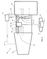
FIG. 1 , asystem 100 for measuring steam quality in asteam turbine 102 according to an embodiment of this invention is shown.System 100 includes a steam quality measurement (SQM)device 106 configured to measure steam quality insteam turbine 102 during operation ofsteam turbine 102, for example, continuously. Afirst end 107 ofSQM device 106 is coupled tosteam turbine 102. As known in the art,steam turbine 102 will emit steam exhaust through an exhaust (not shown). Steam exhaust emitted fromsteam turbine 102 is illustrated byarrows 101. During operation,exhaust steam 101 will be emitted fromsteam turbine 102 intocondenser 104 to be condensed and recycled for further use insteam turbine 102. Depending on the specific arrangement ofsteam turbine 102 andcondenser 108, there may also be atransition piece 120 betweensteam turbine 102 andcondenser 108.Transition piece 120 can be any shape or material desired, configured todirect steam exhaust 101 fromsteam turbine 102 intocondenser 108. - As shown in
FIG. 1 ,SQM device 106 is coupled tosteam turbine 102 in order to allow at least some ofexhaust steam 101 to flow throughSQM device 106. It is understood that one of ordinary skill in the art could coupleSQM device 106 andsteam turbine 102 through anappropriate piping configuration 103 in any now known or later developed manner. -
SQM device 106 can comprise any now known or later developed means for measuring steam quality. Examples ofSQM devices 106 that can be used in connection with embodiments of this invention include those disclosed in the following patents:U.S. Pat. No. 4,769,593 ,U.S. Pat. No. 4,849,988 ,U.S. Pat. No. 4,753,106 ,U.S. Pat. No. 4,876,897 andU.S. Pat. No. 4,836,032 . -
Steam exhaust 101 emitted fromsteam turbine 102 is typically below atmospheric pressure, therefore, in order to draw at least some ofsteam exhaust 101 throughSQM device 106, anejector 108 is provided.Ejector 108 is coupled toSQM device 106 at asecond end 109 ofSQM device 106.Second end 109 ofSQM device 106 is generally oppositefirst end 107 ofSQM device 106 which is coupled tosteam turbine 102. In other words,steam turbine 102,SQM device 106 andejector 108 are arranged substantially in-line such thatejector 108 can drawsteam exhaust 101 throughSQM device 106 as discussed herein. -
Ejector 108 operates as a typical injector/ejector as known in the art using the Venturi effect to draw fluid through a nozzle. For example, as shown inFIG. 1 ,ejector 108 can include a converging-divergingnozzle 113 used to convert pressure energy of amotive fluid 115 to velocity energy which creates alow pressure zone 117 within the converging-divergingnozzle 113 that draws insteam exhaust 101.Ejector 108 is coupled to amotive fluid source 112 to providemotive fluid 115 toejector 108. The motive fluid source can providemotive fluid 115 in the form of air or steam that is at a higher pressure thansteam exhaust 101, and can be provided via anappropriate piping configuration 110 toejector 108. The motive fluid can also be steam exhaust from a point further upstream in steam turbine 102 (e.g., steam exhaust that has not yet exited steam turbine 102) as that steam exhaust would be at a higher pressure thansteam exhaust 101 that has been emitted fromsteam turbine 102. Thephantom lines 111 show an example of how that higher pressure steam can be routed toejector 108 to be used as motive fluid. Depending on the requirements ofSQM device 106 that is used,ejector 108 can be configured to draw a requisite amount ofsteam exhaust 101 throughSQM device 106. -
Ejector 108 draws a portion ofsteam exhaust 101 throughSQM device 106 so thatSQM device 106 can measure the quality of the portion ofsteam exhaust 101 being emitted fromsteam turbine 102 during operation ofsteam turbine 102. In one embodiment,SQM device 106 can continuously, i.e., without interruption, measure the quality of the portion ofsteam exhaust 101 during operation ofsteam turbine 102. In other embodiments,system 100 can be configured such that (1) the measurement ofsteam exhaust 101 is part of the operation of the system, (2) the measurement ofsteam exhaust 101 is automatically made and can be recorded at pre-determined time increments, (3) the measurement ofsteam exhaust 101 does not require a change in the operation of the system for the purpose of making the measurement, and/or (4) the time required to perform the measurement ofsteam exhaust 101 for one scan is very small relative to the operation of the system. - The results of the measurement from
SQM device 106 can be outputted or displayed in any known means, including on anindicator 114, stored in a memory (database, files, etc.) of an electronic storage device 116 (such as a computer, flash drive, or other commonly known storage device) and/or used as a feedback item for acontrol system 118. Once the portion ofsteam exhaust 101 has passed throughSQM device 106, the portion ofsteam exhaust 101 is emitted intocondenser 104 to be condensed and recycled for further use insteam turbine 102. - While
system 100 is discussed herein in connection with measuring steam quality as it exits the exhaust ofturbine 102, it is understood thatsystem 100 can also be used to measure the steam quality in any area of the turbine where moisture is present, such as feed water heaters, steam seal systems, and any other steam turbine admissions and extractions points. It is also noted that whileFIG. 1 showsSQM device 106 andejector 108 as being insidecondenser 104, near the point at whichsteam exhaust 101 enterscondenser 104, other configurations may be possible. For example, SQM device andejector 108 may be located right at the point at whichsteam exhaust 101 enterscondenser 104 or may be further away from that point. In another embodiment, one or both ofSQM device 106 andejector 108 can be outsidecondenser 104. For example, as shown inFIG. 2 ,SQM device 106 andejector 108 are positioned intransition piece 120 betweensteam turbine 102 andcondenser 104. - In another embodiment, a method of measuring steam
quality using system 100 is disclosed. The method includes receivingsteam exhaust 101 fromsteam turbine 102 atfirst end 107 ofSQM device 106, drawing a portion ofsteam exhaust 101 throughSQM device 106 by couplingejector 108 tosecond end 109 ofSQM device 106 and passingmotive fluid 115 at a higher pressure thansteam exhaust 101 throughejector 108 to draw the portion ofsteam exhaust 108 throughSQM device 106, and measuring the steam quality of the portion ofsteam exhaust 101 as the portion passes throughSQM device 106. - The terms "first," "second," and the like, herein do not denote any order, quantity, or importance, but rather are used to distinguish one element from another, and the terms "a" and "an" herein do not denote a limitation of quantity, but rather denote the presence of at least one of the referenced item. The modifier "about" used in connection with a quantity is inclusive of the stated value and has the meaning dictated by the context, (e.g., includes the degree of error associated with measurement of the particular quantity). The suffix "(s)" as used herein is intended to include both the singular and the plural of the term that it modifies, thereby including one or more of that term (e.g., the metal(s) includes one or more metals).
- While various embodiments are described herein, it will be appreciated from the specification that various combinations of elements, variations or improvements therein may be made by those skilled in the art, and are within the scope of the invention. In addition, many modifications may be made to adapt a particular situation or material to the teachings of the invention without departing from essential scope thereof. Therefore, it is intended that the invention not be limited to the particular embodiment disclosed as the best mode contemplated for carrying out this invention, but that the invention will include all embodiments falling within the scope of the appended claims.
Claims (15)
- A system (100) for measuring steam quality, the system (100) comprising:an inlet for receiving a steam exhaust (101) from a steam turbine (102);a steam quality measurement (SQM) device (106), a first end (107) of the SQM device (106) coupled to the steam turbine (102), the SQM device (106) configured to measure steam quality; andan ejector (108), wherein one end of the ejector (108) is coupled to a second end (109) of the SQM device (106) and one end of the ejector (108) is coupled to a source of motive fluid (112, 115) at a higher pressure than the steam exhaust (101), the ejector (108) configured to draw a portion of the steam exhaust (101) through the SQM device (106).
- The system of claim 1, wherein the SQM device (106) measures the steam quality of the portion of the steam exhaust (101) during operation of the steam turbine (102).
- The system of claim 1 or 2, wherein the SQM device (106) continuously measures the steam quality of the portion of the steam exhaust (101).
- The system of any of the preceding claims, wherein the first end (107) of the SQM device (106) to which the exhaust is coupled is opposite the second end (109) of the SQM device (106) to which the ejector (108) is coupled.
- The system of any of the preceding claims, wherein the SQM device (106) outputs a result of the steam quality measurement to one or more of the following devices: an indicator (114) configured to display the results, an electronic storage device (116) configured to store the results, and a control system (118) configured to receive the results as a feedback item.
- The system of any of the preceding claims, further comprising a condenser (104, 108) for receiving the portion of the steam exhaust (101) after the portion has passed through the SQM device (106).
- A method of measuring steam quality, the method comprising:receiving an exhaust of a steam turbine (102) at a first end (107) of a steam quality measurement (SQM) device (106), the SQM device (106) configured to measure steam quality;drawing a portion of the steam exhaust (101) through the SQM device (106) by coupling an ejector (108) to a second end (109) of the SQM device (106) and passing motive fluid (112, 115) at a higher pressure than the steam exhaust (101) through the ejector (108) to draw the portion of the steam exhaust (101) through the SQM device (106); andmeasuring the steam quality of the portion of the steam exhaust (101) as the portion passes through the SQM device (106).
- The method of claim 7, wherein the SQM device (106) measures the steam quality of the portion of the steam exhaust (101) during operation of the steam turbine (102).
- The method of claim 7 or 8, wherein the SQM device (106) continuously measures the steam quality of the portion of the steam exhaust (101).
- The method of any of claims 7 to 9, wherein the first end (107) of the SQM device (106) to which the exhaust is coupled is opposite the second end (109) of the SQM device (106) to which the ejector (108) is coupled.
- The method of any of claims 7 to 10, further comprising outputting a result of the steam quality measurement to one or more of the following devices: an indicator (114) configured to display the results, an electronic storage device (116) configured to store the results, and a control system (118) configured to receive the results as a feedback item.
- The method of any of claims 7 to 11, further comprising emitting the portion of the steam exhaust (101) to a condenser (104, 108) after the portion of the steam exhaust (101) has passed through the SQM device (106).
- A steam turbine (102) comprising:a turbine section having an exhaust, the exhaust configured to emit steam exhaust (101);a steam quality measurement (SQM) device (106), coupled to the exhaust at a first end (107) of the SQM device (106), the SQM device (106) configured to measure steam quality; andan ejector (108), wherein one end of the ejector (108) is coupled to a second end (109) of the SQM device (106) and one end of the ejector (108) is coupled to a source of motive fluid (112, 115) at a higher pressure than the steam exhaust (101), the ejector (108) configured to draw a portion of the steam exhaust (101) through the SQM device (106).
- The steam turbine of claim 13, wherein the SQM device (106) measures the steam quality of the portion of the steam exhaust (101) during operation of the steam turbine (102).
- The steam turbine of claim 13 or 14, wherein the SQM device (106) continuously measures the steam quality of the portion of the steam exhaust (101).
Applications Claiming Priority (1)
| Application Number | Priority Date | Filing Date | Title |
|---|---|---|---|
| US12/428,428 US8100580B2 (en) | 2009-04-22 | 2009-04-22 | Measurement of steam quality in steam turbine |
Publications (2)
| Publication Number | Publication Date |
|---|---|
| EP2243936A1 true EP2243936A1 (en) | 2010-10-27 |
| EP2243936B1 EP2243936B1 (en) | 2012-12-19 |
Family
ID=42313030
Family Applications (1)
| Application Number | Title | Priority Date | Filing Date |
|---|---|---|---|
| EP10160408A Not-in-force EP2243936B1 (en) | 2009-04-22 | 2010-04-20 | Measurement of steam quality in steam turbine |
Country Status (4)
| Country | Link |
|---|---|
| US (1) | US8100580B2 (en) |
| EP (1) | EP2243936B1 (en) |
| JP (1) | JP2010255631A (en) |
| RU (1) | RU2010115646A (en) |
Cited By (3)
| Publication number | Priority date | Publication date | Assignee | Title |
|---|---|---|---|---|
| US8671688B2 (en) | 2011-04-13 | 2014-03-18 | General Electric Company | Combined cycle power plant with thermal load reduction system |
| US9222410B2 (en) | 2011-04-13 | 2015-12-29 | General Electric Company | Power plant |
| CN109540526B (en) * | 2018-12-09 | 2021-10-15 | 西安航天动力试验技术研究所 | Turbine injection system used in direct connection test of ramjet engine |
Families Citing this family (2)
| Publication number | Priority date | Publication date | Assignee | Title |
|---|---|---|---|---|
| US8433526B2 (en) * | 2010-11-12 | 2013-04-30 | General Electric Company | Method and system for steam quality monitoring |
| CN104483152B (en) * | 2014-12-19 | 2017-03-29 | 东南大学 | The heat consumption rate assay method of non-reheat backheat combined-circulation unit |
Citations (10)
| Publication number | Priority date | Publication date | Assignee | Title |
|---|---|---|---|---|
| US3972196A (en) * | 1974-05-10 | 1976-08-03 | Westinghouse Electric Corporation | Steam pressure increasing device for drive turbines |
| WO1988003647A1 (en) * | 1986-11-07 | 1988-05-19 | Kay-Ray, Inc. | Steam quality meter |
| US4769593A (en) | 1986-06-10 | 1988-09-06 | Conoco Inc. | Method and apparatus for measurement of steam quality |
| US4788848A (en) | 1986-04-10 | 1988-12-06 | Chevron Research Company | Chemical tracer determination of steam quality |
| US4836032A (en) | 1988-03-07 | 1989-06-06 | Texaco, Inc. | Method of determining the quality of steam for stimulating hydrocarbon production |
| US4849988A (en) | 1988-02-19 | 1989-07-18 | Texaco Inc. | Apparatus and method for measuring the quality of steam |
| US4876897A (en) | 1987-12-10 | 1989-10-31 | The Foxboro Company | Steam quality measurement apparatus and method |
| US5307832A (en) * | 1992-10-26 | 1994-05-03 | Texaco Inc. | Method and apparatus for automatically transferring and measuring wet steam between priority and secondary users |
| US6146088A (en) * | 1996-04-23 | 2000-11-14 | Martinez; Michele | Process for the rotational driving of a turbine by means of an ejector device |
| DE102008044477A1 (en) * | 2007-08-31 | 2009-03-05 | General Electric Co. | Exhaust gas temperature device for system for regulating temperature of exhaust gases of gas turbine, has line, which is arranged to receive part of exhaust gases of gas turbine |
Family Cites Families (9)
| Publication number | Priority date | Publication date | Assignee | Title |
|---|---|---|---|---|
| US3873817A (en) * | 1972-05-03 | 1975-03-25 | Westinghouse Electric Corp | On-line monitoring of steam turbine performance |
| US4679947A (en) * | 1985-07-16 | 1987-07-14 | Engineering Measurements Co. | Method and apparatus for measuring steam quality |
| US5005351A (en) * | 1990-02-26 | 1991-04-09 | Westinghouse Electric Corp. | Power plant condenser control system |
| US6223535B1 (en) * | 1998-10-23 | 2001-05-01 | Union Oil Company Of California | Geothermal steam processing |
| US7034302B2 (en) * | 2002-09-19 | 2006-04-25 | Battelle Energy Alliance, Llc | Optical steam quality measurement system and method |
| JP4074237B2 (en) * | 2003-09-12 | 2008-04-09 | 株式会社テイエルブイ | Steam dryness measuring device |
| US7021126B1 (en) * | 2004-09-15 | 2006-04-04 | General Electric Company | Methods for low-cost estimation of steam turbine performance |
| GB2436128B (en) * | 2006-03-16 | 2008-08-13 | Rolls Royce Plc | Gas turbine engine |
| US9217566B2 (en) * | 2007-03-27 | 2015-12-22 | Boyle Energy Services & Technology, Inc. | Method and apparatus for commissioning power plants |
-
2009
- 2009-04-22 US US12/428,428 patent/US8100580B2/en not_active Expired - Fee Related
-
2010
- 2010-04-20 EP EP10160408A patent/EP2243936B1/en not_active Not-in-force
- 2010-04-20 JP JP2010096575A patent/JP2010255631A/en not_active Withdrawn
- 2010-04-21 RU RU2010115646/06A patent/RU2010115646A/en not_active Application Discontinuation
Patent Citations (11)
| Publication number | Priority date | Publication date | Assignee | Title |
|---|---|---|---|---|
| US3972196A (en) * | 1974-05-10 | 1976-08-03 | Westinghouse Electric Corporation | Steam pressure increasing device for drive turbines |
| US4788848A (en) | 1986-04-10 | 1988-12-06 | Chevron Research Company | Chemical tracer determination of steam quality |
| US4769593A (en) | 1986-06-10 | 1988-09-06 | Conoco Inc. | Method and apparatus for measurement of steam quality |
| WO1988003647A1 (en) * | 1986-11-07 | 1988-05-19 | Kay-Ray, Inc. | Steam quality meter |
| US4753106A (en) | 1986-11-07 | 1988-06-28 | Kay-Ray, Inc. | Steam quality meter |
| US4876897A (en) | 1987-12-10 | 1989-10-31 | The Foxboro Company | Steam quality measurement apparatus and method |
| US4849988A (en) | 1988-02-19 | 1989-07-18 | Texaco Inc. | Apparatus and method for measuring the quality of steam |
| US4836032A (en) | 1988-03-07 | 1989-06-06 | Texaco, Inc. | Method of determining the quality of steam for stimulating hydrocarbon production |
| US5307832A (en) * | 1992-10-26 | 1994-05-03 | Texaco Inc. | Method and apparatus for automatically transferring and measuring wet steam between priority and secondary users |
| US6146088A (en) * | 1996-04-23 | 2000-11-14 | Martinez; Michele | Process for the rotational driving of a turbine by means of an ejector device |
| DE102008044477A1 (en) * | 2007-08-31 | 2009-03-05 | General Electric Co. | Exhaust gas temperature device for system for regulating temperature of exhaust gases of gas turbine, has line, which is arranged to receive part of exhaust gases of gas turbine |
Cited By (3)
| Publication number | Priority date | Publication date | Assignee | Title |
|---|---|---|---|---|
| US8671688B2 (en) | 2011-04-13 | 2014-03-18 | General Electric Company | Combined cycle power plant with thermal load reduction system |
| US9222410B2 (en) | 2011-04-13 | 2015-12-29 | General Electric Company | Power plant |
| CN109540526B (en) * | 2018-12-09 | 2021-10-15 | 西安航天动力试验技术研究所 | Turbine injection system used in direct connection test of ramjet engine |
Also Published As
| Publication number | Publication date |
|---|---|
| JP2010255631A (en) | 2010-11-11 |
| RU2010115646A (en) | 2011-10-27 |
| US20100272147A1 (en) | 2010-10-28 |
| US8100580B2 (en) | 2012-01-24 |
| EP2243936B1 (en) | 2012-12-19 |
Similar Documents
| Publication | Publication Date | Title |
|---|---|---|
| EP2243936B1 (en) | Measurement of steam quality in steam turbine | |
| US10101186B2 (en) | Method and measuring apparatus for determining specific quantities for gas quality | |
| US7600417B2 (en) | Ultrasonic-densiometer mass flow sensor for use in flow metering units | |
| US9746394B2 (en) | Bench test, for the characterization of a flow of a two-phase fluid | |
| US9255527B2 (en) | Use of an emissions sensor to control fuel flow staging | |
| US9429481B2 (en) | Apparatus and method for measuring total air temperature within an airflow | |
| Chen et al. | Turbine blade platform film cooling with simulated swirl purge flow and slashface leakage conditions | |
| JP2014074405A5 (en) | ||
| US20130305737A1 (en) | System and method for heat recovery in a gas turbine engine | |
| KR101639203B1 (en) | Gas dosage control for gas engine | |
| JP5727723B2 (en) | Apparatus and method for inspecting a compressor | |
| CN102057263A (en) | Method and device for detecting capacity changes in a fluid and turbine | |
| CZ20022054A3 (en) | Steam turbine and method for measuring vibration of moving blade | |
| Katharina et al. | 1154 BURNING VELOCITIES OF HYDROGEN-METHANE-AIR MIXTURES AT HIGHLY STEAM-DILUTED CONDITIONS | |
| US20190277163A1 (en) | Steam turbine exhaust chamber and steam turbine system | |
| Paxson et al. | Operability of an ejector enhanced pulse combustor in a gas turbine environment | |
| US11346255B2 (en) | Method and controller for preventing formation of droplets in a heat exchanger | |
| US8646278B2 (en) | Condition measurement apparatus and method | |
| Pillala et al. | A linear cascade tunnel for flow investigations of steam turbine rotor tip blades in subsonic nucleating flows | |
| US20060233634A1 (en) | Method of indicating sealing steam temperature and related apparatus | |
| MX388760B (en) | TUBE TURBINES IN TEMPERATURE TRANSFER SYSTEMS. | |
| CN105651518B (en) | A kind of measuring method of test bay state point analog parameter | |
| Park et al. | A starting procedure of supersonic ejector to minimize primary pressure load | |
| CN117491021A (en) | A bench air inlet flow adjustment and metering system and its use method | |
| JP5949125B2 (en) | Blast furnace pulverized coal injection method and combustion-supporting gas injection abnormality detection device |
Legal Events
| Date | Code | Title | Description |
|---|---|---|---|
| PUAI | Public reference made under article 153(3) epc to a published international application that has entered the european phase |
Free format text: ORIGINAL CODE: 0009012 |
|
| AK | Designated contracting states |
Kind code of ref document: A1 Designated state(s): AT BE BG CH CY CZ DE DK EE ES FI FR GB GR HR HU IE IS IT LI LT LU LV MC MK MT NL NO PL PT RO SE SI SK SM TR |
|
| AX | Request for extension of the european patent |
Extension state: AL BA ME RS |
|
| 17P | Request for examination filed |
Effective date: 20110427 |
|
| REG | Reference to a national code |
Ref country code: DE Ref legal event code: R079 Ref document number: 602010004144 Country of ref document: DE Free format text: PREVIOUS MAIN CLASS: F01K0017060000 Ipc: F01D0021000000 |
|
| RIC1 | Information provided on ipc code assigned before grant |
Ipc: F02C 6/00 20060101ALI20120507BHEP Ipc: F01K 13/00 20060101ALI20120507BHEP Ipc: F22B 35/16 20060101ALI20120507BHEP Ipc: F01K 17/06 20060101ALI20120507BHEP Ipc: F01D 21/00 20060101AFI20120507BHEP |
|
| GRAP | Despatch of communication of intention to grant a patent |
Free format text: ORIGINAL CODE: EPIDOSNIGR1 |
|
| GRAS | Grant fee paid |
Free format text: ORIGINAL CODE: EPIDOSNIGR3 |
|
| GRAA | (expected) grant |
Free format text: ORIGINAL CODE: 0009210 |
|
| AK | Designated contracting states |
Kind code of ref document: B1 Designated state(s): AT BE BG CH CY CZ DE DK EE ES FI FR GB GR HR HU IE IS IT LI LT LU LV MC MK MT NL NO PL PT RO SE SI SK SM TR |
|
| REG | Reference to a national code |
Ref country code: GB Ref legal event code: FG4D |
|
| REG | Reference to a national code |
Ref country code: CH Ref legal event code: EP |
|
| REG | Reference to a national code |
Ref country code: AT Ref legal event code: REF Ref document number: 589538 Country of ref document: AT Kind code of ref document: T Effective date: 20130115 |
|
| REG | Reference to a national code |
Ref country code: DE Ref legal event code: R096 Ref document number: 602010004144 Country of ref document: DE Effective date: 20130207 |
|
| PG25 | Lapsed in a contracting state [announced via postgrant information from national office to epo] |
Ref country code: ES Free format text: LAPSE BECAUSE OF FAILURE TO SUBMIT A TRANSLATION OF THE DESCRIPTION OR TO PAY THE FEE WITHIN THE PRESCRIBED TIME-LIMIT Effective date: 20130330 Ref country code: LT Free format text: LAPSE BECAUSE OF FAILURE TO SUBMIT A TRANSLATION OF THE DESCRIPTION OR TO PAY THE FEE WITHIN THE PRESCRIBED TIME-LIMIT Effective date: 20121219 Ref country code: SE Free format text: LAPSE BECAUSE OF FAILURE TO SUBMIT A TRANSLATION OF THE DESCRIPTION OR TO PAY THE FEE WITHIN THE PRESCRIBED TIME-LIMIT Effective date: 20121219 Ref country code: NO Free format text: LAPSE BECAUSE OF FAILURE TO SUBMIT A TRANSLATION OF THE DESCRIPTION OR TO PAY THE FEE WITHIN THE PRESCRIBED TIME-LIMIT Effective date: 20130319 Ref country code: HR Free format text: LAPSE BECAUSE OF FAILURE TO SUBMIT A TRANSLATION OF THE DESCRIPTION OR TO PAY THE FEE WITHIN THE PRESCRIBED TIME-LIMIT Effective date: 20121219 Ref country code: FI Free format text: LAPSE BECAUSE OF FAILURE TO SUBMIT A TRANSLATION OF THE DESCRIPTION OR TO PAY THE FEE WITHIN THE PRESCRIBED TIME-LIMIT Effective date: 20121219 |
|
| REG | Reference to a national code |
Ref country code: NL Ref legal event code: VDEP Effective date: 20121219 Ref country code: AT Ref legal event code: MK05 Ref document number: 589538 Country of ref document: AT Kind code of ref document: T Effective date: 20121219 |
|
| REG | Reference to a national code |
Ref country code: LT Ref legal event code: MG4D |
|
| PG25 | Lapsed in a contracting state [announced via postgrant information from national office to epo] |
Ref country code: GR Free format text: LAPSE BECAUSE OF FAILURE TO SUBMIT A TRANSLATION OF THE DESCRIPTION OR TO PAY THE FEE WITHIN THE PRESCRIBED TIME-LIMIT Effective date: 20130320 Ref country code: LV Free format text: LAPSE BECAUSE OF FAILURE TO SUBMIT A TRANSLATION OF THE DESCRIPTION OR TO PAY THE FEE WITHIN THE PRESCRIBED TIME-LIMIT Effective date: 20121219 Ref country code: SI Free format text: LAPSE BECAUSE OF FAILURE TO SUBMIT A TRANSLATION OF THE DESCRIPTION OR TO PAY THE FEE WITHIN THE PRESCRIBED TIME-LIMIT Effective date: 20121219 |
|
| PG25 | Lapsed in a contracting state [announced via postgrant information from national office to epo] |
Ref country code: BG Free format text: LAPSE BECAUSE OF FAILURE TO SUBMIT A TRANSLATION OF THE DESCRIPTION OR TO PAY THE FEE WITHIN THE PRESCRIBED TIME-LIMIT Effective date: 20130319 Ref country code: IS Free format text: LAPSE BECAUSE OF FAILURE TO SUBMIT A TRANSLATION OF THE DESCRIPTION OR TO PAY THE FEE WITHIN THE PRESCRIBED TIME-LIMIT Effective date: 20130419 Ref country code: CZ Free format text: LAPSE BECAUSE OF FAILURE TO SUBMIT A TRANSLATION OF THE DESCRIPTION OR TO PAY THE FEE WITHIN THE PRESCRIBED TIME-LIMIT Effective date: 20121219 Ref country code: AT Free format text: LAPSE BECAUSE OF FAILURE TO SUBMIT A TRANSLATION OF THE DESCRIPTION OR TO PAY THE FEE WITHIN THE PRESCRIBED TIME-LIMIT Effective date: 20121219 Ref country code: SK Free format text: LAPSE BECAUSE OF FAILURE TO SUBMIT A TRANSLATION OF THE DESCRIPTION OR TO PAY THE FEE WITHIN THE PRESCRIBED TIME-LIMIT Effective date: 20121219 Ref country code: EE Free format text: LAPSE BECAUSE OF FAILURE TO SUBMIT A TRANSLATION OF THE DESCRIPTION OR TO PAY THE FEE WITHIN THE PRESCRIBED TIME-LIMIT Effective date: 20121219 Ref country code: BE Free format text: LAPSE BECAUSE OF FAILURE TO SUBMIT A TRANSLATION OF THE DESCRIPTION OR TO PAY THE FEE WITHIN THE PRESCRIBED TIME-LIMIT Effective date: 20121219 |
|
| PGFP | Annual fee paid to national office [announced via postgrant information from national office to epo] |
Ref country code: DE Payment date: 20130429 Year of fee payment: 4 |
|
| PG25 | Lapsed in a contracting state [announced via postgrant information from national office to epo] |
Ref country code: NL Free format text: LAPSE BECAUSE OF FAILURE TO SUBMIT A TRANSLATION OF THE DESCRIPTION OR TO PAY THE FEE WITHIN THE PRESCRIBED TIME-LIMIT Effective date: 20121219 Ref country code: PT Free format text: LAPSE BECAUSE OF FAILURE TO SUBMIT A TRANSLATION OF THE DESCRIPTION OR TO PAY THE FEE WITHIN THE PRESCRIBED TIME-LIMIT Effective date: 20130419 Ref country code: RO Free format text: LAPSE BECAUSE OF FAILURE TO SUBMIT A TRANSLATION OF THE DESCRIPTION OR TO PAY THE FEE WITHIN THE PRESCRIBED TIME-LIMIT Effective date: 20121219 Ref country code: PL Free format text: LAPSE BECAUSE OF FAILURE TO SUBMIT A TRANSLATION OF THE DESCRIPTION OR TO PAY THE FEE WITHIN THE PRESCRIBED TIME-LIMIT Effective date: 20121219 |
|
| PGFP | Annual fee paid to national office [announced via postgrant information from national office to epo] |
Ref country code: FR Payment date: 20130506 Year of fee payment: 4 |
|
| PLBE | No opposition filed within time limit |
Free format text: ORIGINAL CODE: 0009261 |
|
| STAA | Information on the status of an ep patent application or granted ep patent |
Free format text: STATUS: NO OPPOSITION FILED WITHIN TIME LIMIT |
|
| PG25 | Lapsed in a contracting state [announced via postgrant information from national office to epo] |
Ref country code: DK Free format text: LAPSE BECAUSE OF FAILURE TO SUBMIT A TRANSLATION OF THE DESCRIPTION OR TO PAY THE FEE WITHIN THE PRESCRIBED TIME-LIMIT Effective date: 20121219 |
|
| 26N | No opposition filed |
Effective date: 20130920 |
|
| PG25 | Lapsed in a contracting state [announced via postgrant information from national office to epo] |
Ref country code: MC Free format text: LAPSE BECAUSE OF FAILURE TO SUBMIT A TRANSLATION OF THE DESCRIPTION OR TO PAY THE FEE WITHIN THE PRESCRIBED TIME-LIMIT Effective date: 20121219 Ref country code: CY Free format text: LAPSE BECAUSE OF FAILURE TO SUBMIT A TRANSLATION OF THE DESCRIPTION OR TO PAY THE FEE WITHIN THE PRESCRIBED TIME-LIMIT Effective date: 20121219 |
|
| PG25 | Lapsed in a contracting state [announced via postgrant information from national office to epo] |
Ref country code: IT Free format text: LAPSE BECAUSE OF FAILURE TO SUBMIT A TRANSLATION OF THE DESCRIPTION OR TO PAY THE FEE WITHIN THE PRESCRIBED TIME-LIMIT Effective date: 20121219 |
|
| REG | Reference to a national code |
Ref country code: DE Ref legal event code: R097 Ref document number: 602010004144 Country of ref document: DE Effective date: 20130920 |
|
| REG | Reference to a national code |
Ref country code: IE Ref legal event code: MM4A |
|
| PG25 | Lapsed in a contracting state [announced via postgrant information from national office to epo] |
Ref country code: IE Free format text: LAPSE BECAUSE OF NON-PAYMENT OF DUE FEES Effective date: 20130420 |
|
| REG | Reference to a national code |
Ref country code: DE Ref legal event code: R119 Ref document number: 602010004144 Country of ref document: DE |
|
| REG | Reference to a national code |
Ref country code: CH Ref legal event code: PL |
|
| GBPC | Gb: european patent ceased through non-payment of renewal fee |
Effective date: 20140420 |
|
| REG | Reference to a national code |
Ref country code: FR Ref legal event code: ST Effective date: 20141231 |
|
| REG | Reference to a national code |
Ref country code: DE Ref legal event code: R119 Ref document number: 602010004144 Country of ref document: DE Effective date: 20141101 |
|
| PG25 | Lapsed in a contracting state [announced via postgrant information from national office to epo] |
Ref country code: DE Free format text: LAPSE BECAUSE OF NON-PAYMENT OF DUE FEES Effective date: 20141101 Ref country code: CH Free format text: LAPSE BECAUSE OF NON-PAYMENT OF DUE FEES Effective date: 20140430 Ref country code: GB Free format text: LAPSE BECAUSE OF NON-PAYMENT OF DUE FEES Effective date: 20140420 Ref country code: LI Free format text: LAPSE BECAUSE OF NON-PAYMENT OF DUE FEES Effective date: 20140430 |
|
| PG25 | Lapsed in a contracting state [announced via postgrant information from national office to epo] |
Ref country code: FR Free format text: LAPSE BECAUSE OF NON-PAYMENT OF DUE FEES Effective date: 20140430 Ref country code: MT Free format text: LAPSE BECAUSE OF FAILURE TO SUBMIT A TRANSLATION OF THE DESCRIPTION OR TO PAY THE FEE WITHIN THE PRESCRIBED TIME-LIMIT Effective date: 20121219 |
|
| PG25 | Lapsed in a contracting state [announced via postgrant information from national office to epo] |
Ref country code: SM Free format text: LAPSE BECAUSE OF FAILURE TO SUBMIT A TRANSLATION OF THE DESCRIPTION OR TO PAY THE FEE WITHIN THE PRESCRIBED TIME-LIMIT Effective date: 20121219 |
|
| PG25 | Lapsed in a contracting state [announced via postgrant information from national office to epo] |
Ref country code: TR Free format text: LAPSE BECAUSE OF FAILURE TO SUBMIT A TRANSLATION OF THE DESCRIPTION OR TO PAY THE FEE WITHIN THE PRESCRIBED TIME-LIMIT Effective date: 20121219 |
|
| PG25 | Lapsed in a contracting state [announced via postgrant information from national office to epo] |
Ref country code: MK Free format text: LAPSE BECAUSE OF FAILURE TO SUBMIT A TRANSLATION OF THE DESCRIPTION OR TO PAY THE FEE WITHIN THE PRESCRIBED TIME-LIMIT Effective date: 20121219 Ref country code: LU Free format text: LAPSE BECAUSE OF NON-PAYMENT OF DUE FEES Effective date: 20130420 Ref country code: HU Free format text: LAPSE BECAUSE OF FAILURE TO SUBMIT A TRANSLATION OF THE DESCRIPTION OR TO PAY THE FEE WITHIN THE PRESCRIBED TIME-LIMIT; INVALID AB INITIO Effective date: 20100420 |