EP2243707A2 - Vorrichtung und Verfahren zum Herstellen von Verpackungen mit automatischem Verschluss - Google Patents
Vorrichtung und Verfahren zum Herstellen von Verpackungen mit automatischem Verschluss Download PDFInfo
- Publication number
- EP2243707A2 EP2243707A2 EP10250813A EP10250813A EP2243707A2 EP 2243707 A2 EP2243707 A2 EP 2243707A2 EP 10250813 A EP10250813 A EP 10250813A EP 10250813 A EP10250813 A EP 10250813A EP 2243707 A2 EP2243707 A2 EP 2243707A2
- Authority
- EP
- European Patent Office
- Prior art keywords
- semi
- strips
- rigid strips
- rigid
- flexible
- Prior art date
- Legal status (The legal status is an assumption and is not a legal conclusion. Google has not performed a legal analysis and makes no representation as to the accuracy of the status listed.)
- Withdrawn
Links
Images


Classifications
-
- B—PERFORMING OPERATIONS; TRANSPORTING
- B65—CONVEYING; PACKING; STORING; HANDLING THIN OR FILAMENTARY MATERIAL
- B65B—MACHINES, APPARATUS OR DEVICES FOR, OR METHODS OF, PACKAGING ARTICLES OR MATERIALS; UNPACKING
- B65B9/00—Enclosing successive articles, or quantities of material, e.g. liquids or semiliquids, in flat, folded, or tubular webs of flexible sheet material; Subdividing filled flexible tubes to form packages
- B65B9/10—Enclosing successive articles, or quantities of material, in preformed tubular webs, or in webs formed into tubes around filling nozzles, e.g. extruded tubular webs
- B65B9/20—Enclosing successive articles, or quantities of material, in preformed tubular webs, or in webs formed into tubes around filling nozzles, e.g. extruded tubular webs the webs being formed into tubes in situ around the filling nozzles
- B65B9/207—Enclosing successive articles, or quantities of material, in preformed tubular webs, or in webs formed into tubes around filling nozzles, e.g. extruded tubular webs the webs being formed into tubes in situ around the filling nozzles the web advancing continuously
-
- B—PERFORMING OPERATIONS; TRANSPORTING
- B65—CONVEYING; PACKING; STORING; HANDLING THIN OR FILAMENTARY MATERIAL
- B65B—MACHINES, APPARATUS OR DEVICES FOR, OR METHODS OF, PACKAGING ARTICLES OR MATERIALS; UNPACKING
- B65B61/00—Auxiliary devices, not otherwise provided for, for operating on sheets, blanks, webs, binding material, containers or packages
- B65B61/02—Auxiliary devices, not otherwise provided for, for operating on sheets, blanks, webs, binding material, containers or packages for perforating, scoring, slitting, or applying code or date marks on material prior to packaging
-
- B—PERFORMING OPERATIONS; TRANSPORTING
- B65—CONVEYING; PACKING; STORING; HANDLING THIN OR FILAMENTARY MATERIAL
- B65B—MACHINES, APPARATUS OR DEVICES FOR, OR METHODS OF, PACKAGING ARTICLES OR MATERIALS; UNPACKING
- B65B61/00—Auxiliary devices, not otherwise provided for, for operating on sheets, blanks, webs, binding material, containers or packages
- B65B61/18—Auxiliary devices, not otherwise provided for, for operating on sheets, blanks, webs, binding material, containers or packages for making package-opening or unpacking elements
- B65B61/188—Auxiliary devices, not otherwise provided for, for operating on sheets, blanks, webs, binding material, containers or packages for making package-opening or unpacking elements by applying or incorporating profile-strips, e.g. for reclosable bags
-
- B—PERFORMING OPERATIONS; TRANSPORTING
- B65—CONVEYING; PACKING; STORING; HANDLING THIN OR FILAMENTARY MATERIAL
- B65B—MACHINES, APPARATUS OR DEVICES FOR, OR METHODS OF, PACKAGING ARTICLES OR MATERIALS; UNPACKING
- B65B9/00—Enclosing successive articles, or quantities of material, e.g. liquids or semiliquids, in flat, folded, or tubular webs of flexible sheet material; Subdividing filled flexible tubes to form packages
- B65B9/02—Enclosing successive articles, or quantities of material between opposed webs
- B65B9/04—Enclosing successive articles, or quantities of material between opposed webs one or both webs being formed with pockets for the reception of the articles, or of the quantities of material
- B65B9/042—Enclosing successive articles, or quantities of material between opposed webs one or both webs being formed with pockets for the reception of the articles, or of the quantities of material for fluent material
-
- B—PERFORMING OPERATIONS; TRANSPORTING
- B65—CONVEYING; PACKING; STORING; HANDLING THIN OR FILAMENTARY MATERIAL
- B65B—MACHINES, APPARATUS OR DEVICES FOR, OR METHODS OF, PACKAGING ARTICLES OR MATERIALS; UNPACKING
- B65B9/00—Enclosing successive articles, or quantities of material, e.g. liquids or semiliquids, in flat, folded, or tubular webs of flexible sheet material; Subdividing filled flexible tubes to form packages
- B65B9/06—Enclosing successive articles, or quantities of material, in a longitudinally-folded web, or in a web folded into a tube about the articles or quantities of material placed upon it
- B65B9/08—Enclosing successive articles, or quantities of material, in a longitudinally-folded web, or in a web folded into a tube about the articles or quantities of material placed upon it in a web folded and sealed transversely to form pockets which are subsequently filled and then closed by sealing
- B65B9/087—Enclosing successive articles, or quantities of material, in a longitudinally-folded web, or in a web folded into a tube about the articles or quantities of material placed upon it in a web folded and sealed transversely to form pockets which are subsequently filled and then closed by sealing the web advancing continuously
-
- B—PERFORMING OPERATIONS; TRANSPORTING
- B65—CONVEYING; PACKING; STORING; HANDLING THIN OR FILAMENTARY MATERIAL
- B65B—MACHINES, APPARATUS OR DEVICES FOR, OR METHODS OF, PACKAGING ARTICLES OR MATERIALS; UNPACKING
- B65B9/00—Enclosing successive articles, or quantities of material, e.g. liquids or semiliquids, in flat, folded, or tubular webs of flexible sheet material; Subdividing filled flexible tubes to form packages
- B65B9/06—Enclosing successive articles, or quantities of material, in a longitudinally-folded web, or in a web folded into a tube about the articles or quantities of material placed upon it
- B65B9/08—Enclosing successive articles, or quantities of material, in a longitudinally-folded web, or in a web folded into a tube about the articles or quantities of material placed upon it in a web folded and sealed transversely to form pockets which are subsequently filled and then closed by sealing
- B65B9/093—Enclosing successive articles, or quantities of material, in a longitudinally-folded web, or in a web folded into a tube about the articles or quantities of material placed upon it in a web folded and sealed transversely to form pockets which are subsequently filled and then closed by sealing the web having intermittent motion
-
- B—PERFORMING OPERATIONS; TRANSPORTING
- B65—CONVEYING; PACKING; STORING; HANDLING THIN OR FILAMENTARY MATERIAL
- B65B—MACHINES, APPARATUS OR DEVICES FOR, OR METHODS OF, PACKAGING ARTICLES OR MATERIALS; UNPACKING
- B65B9/00—Enclosing successive articles, or quantities of material, e.g. liquids or semiliquids, in flat, folded, or tubular webs of flexible sheet material; Subdividing filled flexible tubes to form packages
- B65B9/10—Enclosing successive articles, or quantities of material, in preformed tubular webs, or in webs formed into tubes around filling nozzles, e.g. extruded tubular webs
- B65B9/20—Enclosing successive articles, or quantities of material, in preformed tubular webs, or in webs formed into tubes around filling nozzles, e.g. extruded tubular webs the webs being formed into tubes in situ around the filling nozzles
- B65B9/213—Enclosing successive articles, or quantities of material, in preformed tubular webs, or in webs formed into tubes around filling nozzles, e.g. extruded tubular webs the webs being formed into tubes in situ around the filling nozzles the web having intermittent motion
-
- B—PERFORMING OPERATIONS; TRANSPORTING
- B65—CONVEYING; PACKING; STORING; HANDLING THIN OR FILAMENTARY MATERIAL
- B65D—CONTAINERS FOR STORAGE OR TRANSPORT OF ARTICLES OR MATERIALS, e.g. BAGS, BARRELS, BOTTLES, BOXES, CANS, CARTONS, CRATES, DRUMS, JARS, TANKS, HOPPERS, FORWARDING CONTAINERS; ACCESSORIES, CLOSURES, OR FITTINGS THEREFOR; PACKAGING ELEMENTS; PACKAGES
- B65D33/00—Details of, or accessories for, sacks or bags
- B65D33/007—Details of, or accessories for, sacks or bags for facilitating the separation of the two walls, e.g. walls of inequal height, tabs; for maintaining the mouth of the sack or bag open
-
- B—PERFORMING OPERATIONS; TRANSPORTING
- B65—CONVEYING; PACKING; STORING; HANDLING THIN OR FILAMENTARY MATERIAL
- B65D—CONTAINERS FOR STORAGE OR TRANSPORT OF ARTICLES OR MATERIALS, e.g. BAGS, BARRELS, BOTTLES, BOXES, CANS, CARTONS, CRATES, DRUMS, JARS, TANKS, HOPPERS, FORWARDING CONTAINERS; ACCESSORIES, CLOSURES, OR FITTINGS THEREFOR; PACKAGING ELEMENTS; PACKAGES
- B65D33/00—Details of, or accessories for, sacks or bags
- B65D33/16—End- or aperture-closing arrangements or devices
- B65D33/30—Deformable or resilient metal or like strips or bands
-
- B—PERFORMING OPERATIONS; TRANSPORTING
- B65—CONVEYING; PACKING; STORING; HANDLING THIN OR FILAMENTARY MATERIAL
- B65B—MACHINES, APPARATUS OR DEVICES FOR, OR METHODS OF, PACKAGING ARTICLES OR MATERIALS; UNPACKING
- B65B2220/00—Specific aspects of the packaging operation
- B65B2220/08—Creating fin seals as the longitudinal seal on horizontal or vertical form fill seal [FFS] machines
-
- B—PERFORMING OPERATIONS; TRANSPORTING
- B65—CONVEYING; PACKING; STORING; HANDLING THIN OR FILAMENTARY MATERIAL
- B65B—MACHINES, APPARATUS OR DEVICES FOR, OR METHODS OF, PACKAGING ARTICLES OR MATERIALS; UNPACKING
- B65B47/00—Apparatus or devices for forming pockets or receptacles in or from sheets, blanks, or webs, comprising essentially a die into which the material is pressed or a folding die through which the material is moved
- B65B47/04—Apparatus or devices for forming pockets or receptacles in or from sheets, blanks, or webs, comprising essentially a die into which the material is pressed or a folding die through which the material is moved by application of mechanical pressure
-
- B—PERFORMING OPERATIONS; TRANSPORTING
- B65—CONVEYING; PACKING; STORING; HANDLING THIN OR FILAMENTARY MATERIAL
- B65B—MACHINES, APPARATUS OR DEVICES FOR, OR METHODS OF, PACKAGING ARTICLES OR MATERIALS; UNPACKING
- B65B7/00—Closing containers or receptacles after filling
- B65B7/16—Closing semi-rigid or rigid containers or receptacles not deformed by, or not taking-up shape of, contents, e.g. boxes or cartons
- B65B7/162—Closing semi-rigid or rigid containers or receptacles not deformed by, or not taking-up shape of, contents, e.g. boxes or cartons by feeding web material to securing means
- B65B7/164—Securing by heat-sealing
-
- B—PERFORMING OPERATIONS; TRANSPORTING
- B65—CONVEYING; PACKING; STORING; HANDLING THIN OR FILAMENTARY MATERIAL
- B65D—CONTAINERS FOR STORAGE OR TRANSPORT OF ARTICLES OR MATERIALS, e.g. BAGS, BARRELS, BOTTLES, BOXES, CANS, CARTONS, CRATES, DRUMS, JARS, TANKS, HOPPERS, FORWARDING CONTAINERS; ACCESSORIES, CLOSURES, OR FITTINGS THEREFOR; PACKAGING ELEMENTS; PACKAGES
- B65D75/00—Packages comprising articles or materials partially or wholly enclosed in strips, sheets, blanks, tubes, or webs of flexible sheet material, e.g. in folded wrappers
- B65D75/52—Details
- B65D75/58—Opening or contents-removing devices added or incorporated during package manufacture
- B65D75/5805—Opening or contents-removing devices added or incorporated during package manufacture for tearing a side strip parallel and next to the edge, e.g. by means of a line of weakness
Definitions
- This invention relates generally to packaging, and more particularly to a disposable food packaging comprising a pouch made of a film material with an automatic closure feature.
- Flexible film packages are well known in the art and typically comprise disposable pouches commercially produced on high-speed form-fill-seal machines from rolls of plastic film material.
- the flexible film packages have cavities within which pluralities of contents, such as food products, are stored. Consumers often consume only a portion of the package's contents.
- a package reclosability feature allows the user to discharge a portion of the contents through the package opening and then seal the opening to reclose the flexible package.
- reclosable flexible packages have press-to-close zipper closures.
- Press-to-close zippers require alignment of two profiles located on opposing package walls to interlock the closure and reclose the package. This alignment may be cumbersome and/or time consuming for consumers, especially younger or older consumers who may have limited manual dexterity.
- a particulate food product like shredded cheese or bread crumbs, is stored within the flexible package, the particulate may interfere with the alignment of the zipper profiles, which often have narrow channels or tracks.
- the reclosable flexible packages include a slider zipper closure.
- the slider closures on these flexible packages assist with the alignment of the two profiles located on the package walls; however, these slider closures require additional plastic material and manufacturing that come with additional costs. While the sliders allow the users to more easily align the package wall profiles, the slider closures create a slight opening between the slider and the side seal when the package is in the closed configuration. Further, the zipper slider remains on the slider tracks when the package is in the open position and the slider extends into the opening, thereby slightly reducing the size of the pouch opening.
- typical recloseable flexible packages do not automatically reclose themselves. These reclosable flexible packages typically require affirmative manual action to reclose. Thus, the user must remember to close the package and accurately press-to-seal the closure or pull the zipper slider to the closed configuration between each usage. Further, if one of these reclosable flexible packages is inadvertently dropped, while open, the contents may be permitted to spill out. The consumer must remember or have sufficient time to reclose the package to avoid possible spilling or spoilage of the package contents.
- the package described herein comprises a flexible pouch made of film material and a pair of semi-rigid strips attached to the walls of the flexible pouch positioned such that the semi-rigid strips align and bias toward one another. Upon removal of the top portion, the semi-rigid strips are moveable between a closed position and an open position. Further, the semi-rigid strips are configured such that they automatically reclose the package when the strips are released from the open position. The strips may extend along the entire width of the flexible pouch or may extend between the side seals of the pouch.
- the self-closing flexible package having the semi-rigid strips To commercially produce the self-closing flexible package having the semi-rigid strips, high-speed form-fill-seal equipment having a vertical or horizontal configuration may be employed.
- cavities are formed out of film material in an in-line operation such that the strips may be added to the inside or outside surfaces of the film material.
- the semi-rigid strips may be secured to the front and back panels by heat sealing or adhesive bonding.
- a method of mass producing a packaged food product in high-speed form-fill-seal equipment comprises:
- the method further comprises forming a removable top portion in the disposable pouches defined by an area of weakness.
- the first and second semi-rigid strips are attached to inside surfaces of the front and the back panels.
- the first and second semi-rigid strips are attached to outside surfaces of the front and back panels.
- the first and second semi-rigid strips are pre-cut.
- the strip material from which the first and second semi-rigid strips are produced is dispensed from a reel.
- the strip material is wound on the reel in flat form such that the profile of the first and second semi-rigid strips is imparted by a thermal forming tool when the material is unwound from the reel.
- attaching the first and second semi-rigid strips comprises at least one of:
- heat sealing the first and second semi-rigid strips comprises having an external heat seal layer compatible on the first and second semi-rigid strips that is compatible with a sealant on the front and back panels.
- the first and second semi-rigid strips are attached in an orientation parallel to the machine direction.
- the first and second semi-rigid strips are attached in an orientation perpendicular to the machine direction via a strip applicator module configured and arranged to cut and heat-seal the first and second semi-rigid strips to the disposable pouch.
- thermoform-fill-seal equipment comprises:
- securing the first semi-rigid strip to the bottom film comprises heat sealing.
- securing the first semi-rigid strip to the bottom film comprises adhesive bonding.
- the first and second semi-rigid strips are attached to inside surfaces of the front and the back panels.
- the first and second semi-rigid strips are attached to outside surfaces of the front and the back panels.
- the first and second semi-rigid strips are pre-cut.
- strip material from which the first and second semi-rigid strips are dispensed from is wound on a reel.
- the strip material is wound on the reel in flat form such that the profile of the first and second semi-rigid strips is imparted by a thermal forming tool when the material is unwound from the reel.
- the first and second semi-rigid strips are attached in an orientation parallel to the machine direction.
- the first and second semi-rigid strips are attached in an orientation perpendicular to the machine direction via a strip applicator module configured and arranged to cut and heat-seal the first and second semi-rigid strips to the disposable pouch.
- a method for mass producing a packaged food product in a vertical form-fill-seal equipment comprises:
- the semi-rigid strips have formed profiles that align in the same direction such that the semi-rigid strips nest together when the flexible pouch is in a closed position.
- forming a flexible plastic tube from a roll of flexible plastic film further includes forming the flexible film over a forming collar to create the plastic tube.
- the plastic tube has a sealed edge and securing a pair of semi-rigid strips to the flexible film includes forming a top seal in the flexible film having a front and a back panels, the front and back panels each having one of the pair of semi-rigid strips attached thereto.
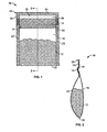
- FIG. 1 comprises a front elevational view of a flexible package as configured in accordance with various embodiments of the invention
- FIG. 2 comprises a cross sectional view of the flexible package of FIG. 1 along line 2-2;
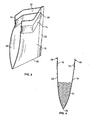
- FIG. 3 comprises an isometric cross sectional view of the flexible package of FIG. 1 in the open configuration
- FIG. 4 comprises a cross sectional view of the flexible package of FIG. 1 in the open configuration
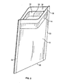
- FIG. 5 comprises a perspective view of the flexible package of FIG. 1 in the open configuration
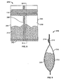
- FIG. 6 comprises a front elevational view of another embodiment of a flexible package
- FIG. 7 comprises a cross sectional view of the flexible package of FIG. 6 along line 7-7;
- FIG. 8 comprises a rear elevational view of another embodiment of a flexible package
- FIG. 9 comprises a cross sectional view of the flexible package of FIG. 8 along line 9-9;
- FIG. 10 comprises a cross sectional view of another embodiment of a flexible package
- FIG. 11 comprises a perspective view of the flexible package of FIG. 10 in the open configuration
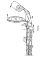
- FIG. 12 comprises a partial perspective view illustrating an apparatus as configured in accordance with an embodiment of the invention.
- FIG. 13A comprises a partial perspective view illustrating an apparatus configured in accordance with an embodiment of the invention
- FIG. 13B comprises a partial perspective view illustrating an apparatus as configured in accordance with an embodiment of the invention.
- FIG. 14 comprises a partial perspective view illustrating an apparatus as configured in accordance with an embodiment of the invention.
- FIG. 15 comprises a perspective view of a of another embodiment of a flexible package
- FIG. 16 comprises a cross sectional view of the flexible package of Fig. 15 ;
- FIG. 17 comprises a perspective view of the flexible package of Fig. 15 in the open configuration
- FIG. 18 comprises a perspective view of another embodiment of a flexible package
- FIG. 19 comprises a cross sectional view of the flexible package of FIG. 18 ;
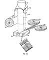
- FIG. 20 comprises a partial perspective view illustrating an apparatus as configured in accordance with an embodiment of the invention.
- a flexible package or pouch with an automatic closure feature is illustrated in Figs. 1-11 .
- the flexible pouch 10 as shown in Figs. 1-5 , may be used for packaging food products 12, such as particulate food products including shredded cheese, cereal, and trail mix, to note but a few.
- the flexible pouch 10 has a pair of curved semi-rigid strips 14, 16 that run parallel to the pouch opening.
- the curved, semi-rigid strips 14, 16 are configured and arranged to nest together and bias toward one another.
- the first and second semi-rigid strips 14, 16 are secured to the opposed front and back panels 18, 20 of the flexible pouch 10 and the biasing of the strips 14, 16 biases the panels 18, 20 to the closed configuration.
- the flexible pouch 10 may be comprised of a flexible film material that is formed using high-speed form-fill-seal equipment.
- the flexible pouch may have a variety of seals, folds, and other features as determined by a variety of considerations, such as the products stored in the pouch and the method of manufacturing the pouch, to note but a few.
- the flexible pouch 10 includes front and back panels 18, 20 that have a side seals 22, a top seal 24, and a bottom fold 26.
- the flexible pouch 10 includes a removable top portion 28.
- the front and back panels 18, 20 have curved semi-rigid strips 14, 16 located thereon.
- the curved semi-rigid strips 14, 16 are movable between an open position permitting dispensing of the food product and a closed position that limits or prevents egress of the food product.
- the side seals 22 extend along the outside edges of the panels 18, 20 to create the pouch 10.
- the side seals 22, top seal 24 and similar seals discussed herein may be conventional heat-seals. Such conventional heat seals may be created by reciprocating heat sealing bars or other suitable sealing apparatus and are well known to those skilled in the art.
- the flexible pouch 10 includes an area of weakness 30 that assist the user with separating the removable top portion 28 from the flexible pouch 10.
- the area of weakness 30 may be a mechanical or laser score line. This line may be linear or non-linear. If the area of weakness is non-linear, the flange at the top of the package (discussed below) may not extend entirely across the package width.
- the area of weakness 30 may include perforations. The score line or perforations may be extended along the entire width of the flexible pouch 10.
- the area of weakness 30 may include a tear initiation feature 32 along only a portion of the pouch, such as, for example, a small V-notch or slit on one edge of the package. For example, as shown in Fig. 1 , the area of weakness 30 may include a tear initiation feature 32 aligned with a score line.
- a hermetic seal 34 is desirable to ensure product freshness.
- the hermetic seal 34 may have a pealably openable characteristic.
- the pealable hermetic seal 34 is positioned below the curved semi-rigid strips 14, 16.
- the hermetic seal 34 may be created by the top seal 24 if the area of weakness 30 takes the form of a score line as opposed to perforations, which would interfere with the hermetic seal 34 created by the top seal 24.
- the flexible pouch 10 may have a tamper evidence feature.
- the front and back panels 18, 20 each have a curved semi-rigid strip 14, 16 secured thereon.
- the curved semi-rigid strips 14, 16 have a slight arc and are positioned on the panels 18, 20 such that the curved strips nest tightly together. More particularly, the curvature of the first curved semi-rigid strip 14 aligns in the same direction as the curvature of the second curved semi-rigid strip 16 as illustrated in Fig. 2 .
- the radius of curvature of the curved semi-rigid strips 14, 16 may be larger or smaller than that illustrated in Fig. 2 .
- the curved semi-rigid strips 14, 16 may have a variety of dimensions.
- the strips 14, 16 may have a radius of curvature from 0.125 to 6.0 inches, a thickness of 0.007 to 0.050 inches, a height of 0.125 to 2.5 inches, and a length of 0.75 to 20 inches.
- the curved semi-rigid strips 14, 16 are about 1.25 inches in height, 5.75 inches in length, with a radius of curvature of 1.25 inches, and a thickness of about 0.015 inches.
- the curved semi-rigid strips 14, 16 may extend the entire width of the package, as shown in Fig.
- the strips 14, 16 may extend in between the side seals 22 such that the strips 14, 16 terminate at the inside margin of the side seal 22.
- Other embodiments are contemplated, such as, for example, an embodiment having curved semi-rigid strips 14, 16 that terminate in the middle of the side seals 22.
- the curved semi-rigid strips 14, 16 bias toward one another to automatically close the flexible pouch 10 upon release from the open position.
- the curved semi-rigid strips 14, 16 are in their stable resting configuration when they are extended to their full length.
- lengthwise tension is induced in the strips 14, 16 such that when the strips are released from that position, they automatically move to the fully extended position which brings the strips 14, 16 together tightly and closes the flexible pouch 10.
- the strips 14, 16 create an audible snap when the flexible package recloses. The audible snap assures the consumer that the package is securely closed and the unused portion of the contents will remain fresh.
- the curved semi-rigid strips 14, 16 are positioned parallel to the opening created at the top of the pouch 10 upon the removal of the top portion 28.
- the curved semi-rigid strips 14, 16 are positioned a distance form the area of weakness 30.
- the strips 14, 16 are positioned about 0.75 inches from the top film edge. This distance may vary and a desired distance may be between 0.125 and 2.0 inches.
- the curved semi-rigid strips 14, 16 may be comprised of a variety of materials including a relatively heat resistant polymer such as polyethylene terephthalate (PET), high impact polystyrene (HIPS), polypropylene (PP), high density polyethylene (HDPE), another of a variety of relatively stiff polymers, or a thin strip of resilient metal such as a thin strip of steel.
- the curved semi-rigid strips 14, 16 may be secured to the panels 18, 20 in a variety of manners such as, for example, by heat sealing or adhesive bonding. Further, the strips 14, 16 may be attached to the inside or outside surfaces of the panels 18, 20.
- the first and second curved semi rigid strips 14, 16 have an external heat seal layer compatible with a sealant on the respective front and back panels 18, 20.
- the semi-rigid spring-loaded strips 14, 16 may be produced in a variety of manners such as by stamping, injection molding, thermoforming, extrusion, or by a combination of two or more of these processes. For example, the strips may be stretched and rapidly quenched after profile extrusion.
- the curved semi-rigid strips 14, 16 may be produced either as separate elements, pairs, or as a continuous ribbon of strip material wound onto a reel. In one embodiment, the curved semi-rigid strips 14, 16 may be brought to the line in pre-cut strips. In another manufacturing process, the curved semi-rigid strips 14, 16 may be formed in-line.
- the material from which the curved semi-rigid strips 14, 16 is formed is wound on a reel in a flat form such that the curvature of the semi-rigid strips 14, 16 is imparted by a forming process such as a thermoforming tool when the material is unwound from the reel.
- a forming process such as a thermoforming tool
- the flexible pouch 10 is illustrated in the open configuration.
- a portion of film material extends, which comprises the panel flanges 36, 38.
- the panel flanges 36, 38 extend above the curved semi-rigid strips 14, 16 and may be grasped by the user.
- the strips 14, 16 are positioned between 0.5 and 1.0 inches from the top edge of the film material.
- the panel flanges 36, 38 may be between 0.25 and 0.8 inches in height.
- Such panel flanges 36, 38 provide loose film for easy grasping, which assists with the opening of the pouch 10.
- the user may manually grasp and pull the front and back panel flanges 36, 38 apart from one another. Pulling the panel flanges 36, 38 with a mild force causes the package to move to a fully open configuration.
- the flexible pouch 10 may be held in the fully open configuration by applying longitudinal compression to the sides of the flexible pouch 10 where the curved semi-rigid strips 14, 16 terminate. Continuous application of such longitudinal compression retains the flexible pouch 10 in the fully open configuration, as shown in Figs. 3 -5 .
- the fully open configuration allows significant access to the food products stored within the flexible pouch 10.
- the flexible package is sized to allow one-hand manual application of the longitudinal compression.
- the spring-tension of the curved semi-rigid strips 14, 16 causes them to snap back to the closed position thereby automatically closing pouch 10.
- the closing action may be rapid and accompanied by an audible snap sound.
- the matching curvature of the curved semi-rigid strips 14, 16 is forced tightly together creating a secure closure at the top of the flexible pouch 10.
- Figs. 6 and 7 there is illustrate another embodiment of a flexible pouch.
- similar flexible pouches are illustrated having slightly different features.
- features of the various embodiments that correspond to features already discussed with respect to previously discussed embodiments are identified using the same reference numeral in combination with a prefix (such as '1') to distinguish the different embodiment.
- flexible pouch 110 corresponds to previously described flexible pouch 10.
- flexible pouch 110 includes side seals 122, a top seal 124 and a bottom seal 142.
- This embodiment may be produced out of two rolls of film material that are heat sealed together.
- the curved semi-rigid strips 114, 116 extend to the outside edges of the side seals 122.
- the flexible pouch 100 comprises a front panel 120 that is generally vertical and a back panel 118 within which a bulge is created to accommodate a plurality of food product 112.
- the flexible pouch 210 includes a bottom seal 242, side folds 244, and a lap or fin seal 246 along the back of the flexible pouch 210.
- the fin seal 246, like side seals 22, may be conventional heat seals.
- the curved semi-rigid strips 214, 216 are secured to the outside surfaces of the front and back panels 218, 220.
- a flexible pouch 310 is illustrated.
- the flexible pouch 310 is similar to the flexible pouch 10 described above except that flexible pouch 310 has only one curved semi-rigid strip 314 secured to one of either the front or back panels 318, 320.
- Such an embodiment functions similarly to the previously discussed embodiments, except that the closure may not be as air-tight as the previous embodiments but the flexible pouch 310 uses less strip material and thus has a cost savings.
- the flexible pouches may affect the particular seals, folds, and various other features of particular flexible pouches.
- a variety of manufacturing methods are available to commercially produce the flexible pouches and a few examples will be discussed herein and illustrated in Figs. 12-14 .
- the flexible pouches may be made in a high-speed form-fill-seal (FFS) operation that produces up to 800 packages per minute.
- the FFS operation may be on a vertical FFS machines as illustrated in Fig. 12 or also may be on a horizontal FFS machine as illustrated in Figs. 13A and 13B or on a horizontal thermoform-fill-seal (HTFFS) machine as shown in Fig. 14 .
- the curved semi-rigid strips may also be secured to the pouches in a variety manners, such as by heat sealing or adhesive bonding via an add-on equipment module designed to work in harmony with the pouch-making machines of the FFS operation.
- the flexible pouches are made in a vertical FFS or bagging line.
- a series of flexible pouches is formed from a roll of film 48, such that the front and back panels of the film material define a cavity.
- a web of the rolled film material is fed over a folding shoulder 50 such as a forming collar and mandrel to provide it with a tubular shape.
- a folding shoulder 50 such as a forming collar and mandrel to provide it with a tubular shape.
- Opposite longitudinal edges of the film are brought together around the fill tube 49.
- the longitudinal edges are sealed, such as by a seal tool 52 to form a fin seal, or overlapped to form a lap seal.
- the curved semi-rigid strips are wound on reels 54.
- the strips are brought into alignment with a reciprocating seal tool 56 for attachment to the walls of the flexible pouch.
- a bottom seal for the pouch is also formed by the reciprocating sealing tool 56, which may include a pair of reciprocating sealing bars.
- the reciprocating sealing bars are heat sealing bars maintained at a desired temperature to apply heat and pressure to the front and rear walls. Further, the heat seal bars are brought together on opposite sides of the tubular web so that heat is conductively transferred to the film from both sides while pressure is applied.
- the sealing bars may be used in an intermittent or continuous operation. In an intermittent operation, the film is stopped while the sealing bars engage the film. In a continuous operation, the sealing bars may move vertically at the machine speed as they engage the film.
- sealing tool 56 attaches the curved semi-rigid strips and creates a top seal in a lower pouch and creates a bottom seal in an upper pouch at roughly the same time.
- sealing tool 56 may contain a reciprocating knife which acts to separate the bottom pouch from the upper pouch.
- the sealing tool 56 has a cutting device associated therewith to create a perforation across the top of the package or a notch at the edge of the package to aid in tear initiation.
- the area of weakness in the pouch is not perforated at the package line but is pre-scored (mechanically or with a laser) at the film manufacturer.
- the strips are attached to flexible pouches such that the curvature of the first curved semi-rigid strip aligns with the curvature of the second curved semi-rigid strip.
- the strips may be attached to the vertical FFS pouch in a variety of manners, e.g., hot melt adhesive, pressure sensitive adhesive, and heat sealing, to note but a few options.
- the curved semi-rigid strips may be applied to the outside surfaces of the walls. In one vertical FFS process, the curved semi-rigid strips have an external heal seal layer compatible with a sealant on the outside surface of the package walls. In one such vertical FFS operation, the curved semi-rigid strips are secured to the front and back panels in a direction perpendicular to the machine direction on the outside surface of the panels.
- the partially formed flexible pouch is then filled with food product, which is introduced into the pouch via the fill tube 49.
- an area of weakness is formed in the flexible pouches to define a removable top portion.
- a notch, score line, or other feature to facilitate removal of the top portion of the package may then be formed near the top of the pouch.
- a hermetic seal may also be created in the disposable pouch.
- the sealing tool 56 may perform a variety of functions simultaneously, including: creating the bottom seal of the pouch that is about to be filled with product; attaching the semi-rigid strips to the upper portion of the front and back panels and creating a peelable heat seal just below the strips on the pouch that was just filled; and having a reciprocating knife or cutting tool which separates the pouch that was just filled from the following one which is about to be filled.
- the reciprocating cutting tool may also create an area of weakness such as a perforation across the top of the package or a notch at the package edge.
- the area of weakness in the pouch is not perforated at the package line but is pre-scored (mechanically or with a laser) at the film manufacturer such that the scored area of weakness is built into the film as it arrives from the manufacturer. If such an approach is taken, the film should be positioned on the packaging machine via optical registration so that the previously imparted score line is in the correct position when the flexible pouch is formed.
- Fig. 13A flexible pouches are manufactured in a horizontal FFS or a flow-form wrapper. Like the vertical process described above, a series of flexible pouches is formed and the film material defines a cavity having front and back panels.
- Fig. 13A illustrates a single roll of film 148 being folded at a folding apparatus 150 and then sealed with a sealing die 152 to form pouch cavities in series with one another. After the film is formed into cavities, the cavities are filled with food product.
- the strip-alignment roller 158 is set at an angle to cause the strips to turn after unwinding and to be redirected so that they are aligned in the proper orientation for attachment to the flexible pouches. As shown in FIG.
- a double roll of strips 154a is located on the reel. As the strips are positioned and sealed to the pouches and the pouches are advanced in the machine direction, the strips are continuously unwound from the roll 154a and advanced in the machine direction along with the pouches. As the double layer of continuous strips 154a is unwound, the strips are dispensed from the roll and positioned between the two front and back panels of the film material. In this embodiment, the strips are sealed to the inside surface of the front and back panels. As shown in Fig. 13A , the seal bars 156 seal the flexible pouch and strips from both sides of the pouch.
- sealing bars 156 are configured to transfer heat through the pouch material, which is thinner than the semi-rigid strips.
- the strips may be of a thicker material and thus, may require more, heat, pressure, or time, to be affected by the heat seal process.
- the sealing bars 156 may also create an area of weakness in the package such as by a cutting device associated therewith.
- a separate mechanical or laser score tool (not shown) may be employed in-line to create the score line in the formed packages.
- the area of weakness such as the score line is already formed in the film when the film arrives from the manufacturer.
- the flexible pouches are made in a horizontal FFS or a flow-wrapper line similar to the example shown in Fig. 13A .
- a series of flexible pouches is formed from a single roll of film 148 that is folded at a folding apparatus 150, such as a folding plow as shown in Fig. 13B , and then sealed with a sealing die 152 to form pouch cavities in series with one another. After the film is formed into cavities, the cavities are filled with food product.
- the horizontal FFS process has two separate reels 154b with curved semi-rigid strips, instead of the single roll of double layer strips 154a shown in Fig. 13A .
- a continuous ribbon of curved semi-rigid material is dispensed to the line from the reel and then secured to the pouch cavities at sealing die 156. It is also contemplated that pre-cut strips may be brought in-line and secured to the flexible film pouches.
- the sealing die 156 also imparts a top seal to the flexible pouch and may also create a peelable seal, if desired.
- the filled cavities are then separated from one another, such as by a reciprocating knife, not shown.
- the flexible pouches are made on horizontal thermoform-fill-seal equipment (TFFS).
- TFFS horizontal thermoform-fill-seal equipment
- such a process may employ two rolls of film material 248a, 248b.
- a series of product cavities are thermoformed from a flexible plastic bottom film 248b, which can then be filled with a food product.
- the forming of the bottom film 248b occurs at thermoforming station 260.
- the curved semi-rigid strips are introduced at the proper position between the top and bottom films. The strips may arrive to the in-line process pre-cut or on a continuous reel of semi-rigid spring strip material that may or may not require further forming processing.
- the curved semi-rigid strips are positioned on two reels 254, mated together with one another at strip roller guide 258, and brought in series to be attached to the flexible pouch.
- This sealing station 256 is generally contained within a vacuum chamber, especially when the food product requires low oxygen vacuum packaging or modified atmosphere packaging.
- an upper moveable heated seal bar 257a and an unheated moveable lower seal support die 257b which act together to apply heat and pressure to the upper and/or lower films, accomplishing all of the necessary heat seals to define the final package (such as the package shown in Figs. 6 and 7 ) including the side seals, the top and bottom seals, the peelable seal below the semi-rigid strips, as well as sealing the curved semi-rigid strips to the top and bottom films.
- the formed flexible pouches move in series to a trim station 262 where the pouches are separated from one another.
- the trim station 262 may also create the area of weakness in the pouches such as by a cutting device.
- a separate mechanical or laser score tool (not shown) may be employed in-line to create the score line in the film as it is unwound from the roll, prior to forming the packages.
- the area of weakness is already formed in the film when the film arrives from the manufacturer. However, if pre-scored film is employed it should be registered on the packaging machine so that the scored line is in the correct position once the pouches have been formed.
- the strips are sealed between the top film 248a and the bottom film 248b such that they are attached to the inside surfaces of the bottom film and the top film.
- the film may have a heat sealable layer on the inside surface which seals to the resin material of the semi-rigid strips.
- the strips have an external heat seal layer compatible with a sealant on the inside surface of the film.
- the film material or substrate of the flexible pouch may be formed as a polymeric sheet of various plastic polymers, copolymers, co-extrusions and/or laminations. Further, the film material may be a monolayer polymeric film or a multilayer laminate comprising an outer layer of durable material and one or more inner barrier layers and sealant layers.
- the multilayer combination may be comprised of polyolefin such as polyethylene (high, medium, low, linear low, and/or ultra low density polymers including metallocene), polypropylene (non-oriented, oriented, and/or biaxially oriented); polybutylene; ethylene vinyl acetate (EVA); polyamides (non-oriented, oriented, and/or biaxially oriented) such as nylon; polyethylene terephthalate (non-oriented, oriented, and/or biaxially oriented); polyvinyl chloride; ethylene vinyl alcohol (EVOH); polyvinylidene chloride (PVDC); polyvinyl alcohol (PVOH); polystyrene; or combinations thereof.
- adhesive tie layers may also be used.
- an illustrative embodiment in Fig. 15 includes a flexible package 400 having a pair of semi-rigid strips 414, 416 with a slight fold therein such that the strips have a crease, angle, or v-shape imparted thereto.
- the partially folded semi-rigid strips 414, 416 extend nearly the entire width of the package and are parallel to the pouch opening.
- the partially folded, semi-rigid strips 414, 416 like previous strips, have matching profiles and are configured to automatically close the package 400 once the partially folded, semi-rigid strips 414, 416 are released from an open position. More particularly, once released from the open position, the strips and associated panels 418, 420 are forced tightly together creating a secure closure at the top of the flexible pouch 400.
- the partially-folded semi-rigid strips 414, 416 are configured and arranged to nest together and bias toward one another.
- the first and second partially-folded, semi-rigid strips 414, 416 are secured to the opposed front and back panels 418, 420 of the flexible pouch 400 such that the profiles of the strips align in the same direction. Further, the biasing of the strips 414, 416 biases the panels 418, 420 to the closed configuration.
- the pouch 400 may be comprised of a thin, flexible film material such as that formed using high-speed form-fill-seal equipment previously discussed.
- the package 400 includes a side seal 422, a top seal 424, and a bottom seal 426, a variety of seals, folds, and other pouch features are contemplated for use with the partially-folded, semi-rigid strips 414, 416.
- the pouch 400 illustrated in Fig. 15 , includes an area of weakness 430 that facilitates removal of the top portion 428.
- the area of weakness 430 by one approach, is positioned a distance below the top seal 424 and a distance above the partially-folded, semi-rigid strips 414, 416 such that a portion of the front and back panels 418, 420 comprises a flange 436, 438 that can be manually grasped and separated to open the package 400 once the top portion 428 has been removed.
- flexible pouch 400 illustrates the partially-folded, semi-rigid strips 414, 416 attached to inside surfaces of the front and back panels 418, 420, as shown in Fig.
- the strips 414, 416 may be affixed to outside surfaces.
- the flexible pouch 10 may include a hermetic seal.
- the hermetic seal may include the top seal 424.
- the hermetic seal may include a pealable hermetic seal 434.
- planar semi-rigid strips 514, 516 include planar semi-rigid strips 514, 516.
- the planar semi-rigid strips 514, 516 extend nearly the entire width of the package and are parallel to the pouch opening.
- planar semi-rigid strips 514, 516 bias toward one another such that the pouch automatically closes when the strips 514, 516 and associated panels 518, 520 are forced tightly together.
- the planar semi-rigid strips 514, 516 have a flat profile and are secured to the front and back panels 518, 520 such that the strips 514, 516 generally overlap.
- planar strips 514, 516 nest together by overlapping or having significant surface to surface contact. Additional configurations for the semi-rigid strips are contemplated.
- the flexible pouch may have a variety of configurations with differing seals, folds, and various other features.
- a number of alterations to the various methods disclosed are contemplated without changing the overall operation of the manufacturing method or the flexible packages produced.
- high-speed form-fill-seal (FFS) operations may produce significant quantities of flexible packages in a relatively short period of time.
- the various processes described above including the vertical manufacturing process of Fig. 12 , the horizontal manufacturing processes of Figs. 13A-14 , and the strip attachment methods discussed herein may be modified or combined for particular manufacturing requirements or limitations.
- a packaging system shown in Fig. 20 , employs a vertical FFS or bagging line similar to that in Fig. 12 albeit with several modifications such that flexible packages are produced having a top seal and two side seals as shown produced in Fig. 13A and 13B .
- the system of Fig. 20 aligns the semi-rigid strips in a direction parallel to machine direction or the movement of the series of pouches.
- flexible pouches are formed from a roll of film 648, such that the front and back panels of the film material define a cavity.
- a web of rolled film material is fed over a folding shoulder 650 to provide the film with a tubular shape.
- Opposite longitudinal edges of the film 648 are brought together around the fill tube 649.
- the longitudinal edges are sealed, such as by seal and attachment tool 652.
- the seal and attachment tool 652 forms a top seal that will span the width of the package opening in between side seals once the flexible package is formed.
- the seal and attachment tool 652 may also attach semi-rigid strips to the film 648.
- the semi-rigid strips are wound on reels 654 and brought into alignment with the film at the seal and attachment tool 652 to be secured to the film. Attachment to the film may be accomplished by a variety of mechanisms. By one approach, heat sealing may be employed to secure the semi-rigid strips to the film. By another approach, an adhesive may be used, such as a hot melt adhesive or a pressure sensitive adhesive.
- the semi-rigid strips may have an external heat seal layer compatible with a sealant on the outside surface of the film comprising the package walls. While the material wound on the reels 654 may have a curvature or profile formed therein, by another approach, the profile or curvature of the semi-rigid strip may be created at the seal and attachment tool 652. In the example of Fig. 20 , the semi-rigid strips, being wound on reels 654, are secured to the film as the series of semi-rigid strips from the reels 654 advances in a direction parallel to the machine direction.
- the seal and attachment tool 652 may also create an area of weakness or a tear initiation feature such as a notch.
- the area of weakness may be pre-scored in the film by the film manufacturer. In such a case, the film 648 may need to be loaded into the packaging system to ensure proper placement of the area of weakness in the flexible pouch.
- the tear initiation feature may be created during other operations as discussed below.
- side seals 622a, 622b of the flexible package 610 may be formed by a reciprocating seal tool 656, which may include a pair of reciprocating sealing bars.
- the reciprocating sealing bars are heat sealing bars maintained at a desired temperature to apply heat and pressure to the tubular web to create the flexible packages.
- the heat seal bars 656 illustrated in Fig. 20 are brought together on opposite sides of the tubular web so that heat is conductively transferred to the film from both sides while pressure is applied.
- the sealing bars may be used in an intermittent or continuous operation. In an intermittent operation, the film is stopped while the sealing bars engage the film. In a continuous operation, the sealing bars may move vertically at the machine speed as they engage the film.
- sealing tool 656 seals the side seal 622b of a lower pouch and creates another side seal 622a for another, upper pouch, at substantially the same time.
- an upper flexible pouch has a first side seal 622a created therein.
- the upper flexible pouch may be filled with food and lowered to form the second side seal sealed 622b therein.
- sealing tool 656 may create a tear initiation feature or tool 656 may contain a reciprocating knife that is configured to separate the bottom or lowered pouch from the upper pouch.
- the pouch may then be filled with product, which is introduced via the fill tube 649. Either before or after the flexible pouch 610 has been filled with food, the pouch may advance downward to become the lower or bottom pouch, then, the second side seal 622b is created in the package thereby enclosing the food product in the flexible pouch 610.
- sealing and attachment tool 652 can create a top seal of the pouch and attach the semi-rigid strips.
- tool 652 may also create a peelable heat seal just below the semi-rigid strips and may impart the curvature or formed profile of the semi-rigid strips.
- seal tool 656 creates side seals on two different packages simultaneously and may also separate these packages.
- seal tool 656 may also include a cutting device to create a notch at the edge of the package to aid in tear initiation or may create an area of weakness in the film. The cutting device may also be used to separate the packages as mentioned via reciprocating knife.
Applications Claiming Priority (1)
| Application Number | Priority Date | Filing Date | Title |
|---|---|---|---|
| US12/429,855 US20090266036A1 (en) | 2008-04-24 | 2009-04-24 | Flexible package having an automatic closure feature |
Publications (2)
| Publication Number | Publication Date |
|---|---|
| EP2243707A2 true EP2243707A2 (de) | 2010-10-27 |
| EP2243707A3 EP2243707A3 (de) | 2012-09-19 |
Family
ID=42561099
Family Applications (1)
| Application Number | Title | Priority Date | Filing Date |
|---|---|---|---|
| EP10250813A Withdrawn EP2243707A3 (de) | 2009-04-24 | 2010-04-22 | Vorrichtung und Verfahren zum Herstellen von Verpackungen mit automatischem Verschluss |
Country Status (7)
| Country | Link |
|---|---|
| US (1) | US20090266036A1 (de) |
| EP (1) | EP2243707A3 (de) |
| CN (1) | CN101920794A (de) |
| AR (1) | AR076414A1 (de) |
| BR (1) | BRPI1001168A2 (de) |
| CO (1) | CO6270034A1 (de) |
| MX (1) | MX2010004522A (de) |
Families Citing this family (26)
| Publication number | Priority date | Publication date | Assignee | Title |
|---|---|---|---|---|
| ITVR20090188A1 (it) * | 2009-11-13 | 2011-05-14 | Bvm S R L | Metodo per il confezionamento di prodotto nonche' macchina confezionatrice a caricamento manuale |
| PL2913281T3 (pl) | 2010-07-09 | 2017-08-31 | Intercontinental Great Brands Llc | Opakowanie dla ułożonych sztuk produktu mających oddzielany wzór rozmieszczenia |
| US10427851B2 (en) * | 2010-12-30 | 2019-10-01 | Mark Steele | Package with heat score |
| US8893457B2 (en) * | 2011-02-16 | 2014-11-25 | Cryovac, Inc. | Easy open and reclosable package with die-cut web and discrete tape anchored to second side panel |
| US8800250B2 (en) * | 2011-02-16 | 2014-08-12 | Cryovac, Inc. | Easy open and reclosable package with discrete laminate, with die-cut, anchored to second side panel |
| DE102011080462A1 (de) * | 2011-08-04 | 2013-02-07 | Windmöller & Hölscher Kg | Verfahren und Vorrichtung zum Herstellen, Befüllen und Verschließen von Säcken sowie ein Sack |
| US20130108881A1 (en) * | 2011-10-31 | 2013-05-02 | Terry Ann Clark | Hermetically Sealable And High Oxygen Barrier Oriented Packaging Films |
| US10660428B2 (en) * | 2012-12-10 | 2020-05-26 | Pure Safety Group, Inc. | Small parts pouch with self-sealing closure |
| JP6025225B2 (ja) * | 2012-12-18 | 2016-11-16 | 株式会社タイキ | 皮膚用薬液保持体の包装体の製造方法 |
| WO2014150442A1 (en) * | 2013-03-15 | 2014-09-25 | Mars, Incorporated | Easy-to-open, resealable food product packaging, systems and methods |
| CZ305349B6 (cs) * | 2013-12-06 | 2015-08-12 | Velteko S.R.O. | Způsob aplikace páskového uzávěru na fóliovou hadici ve vertikálním balicím stroji |
| EP3178752B1 (de) * | 2014-08-04 | 2019-03-20 | Grupo P.I. Mabe, S.A. de C.V. | Beutel zum verpacken von einweghygieneartikeln |
| DK178745B1 (en) | 2014-08-08 | 2016-12-19 | Kontorpark Aps I Likvidation | Container for fluids |
| NO20141330A1 (no) | 2014-11-07 | 2016-05-09 | Fimtech As | Doseringsanordning |
| JP6859018B2 (ja) * | 2015-02-24 | 2021-04-14 | 株式会社Mizkan Holdings | 包装物品 |
| ITUB20155356A1 (it) * | 2015-10-30 | 2017-04-30 | Simone Abate | Sacchetto per conservare prodotti sottovuoto e metodo per la sua realizzazione. |
| CN108602575B (zh) | 2015-11-16 | 2021-01-05 | 自动化包装系统公司 | 带有切口的袋 |
| US10532856B2 (en) * | 2015-12-31 | 2020-01-14 | Bemis Company, Inc. | Self-closing manually re-openable package |
| CN106628561A (zh) * | 2016-12-20 | 2017-05-10 | 重庆市长寿区舒福食品有限公司 | 便于开口的包装袋 |
| JP2018147050A (ja) * | 2017-03-01 | 2018-09-20 | グローリー株式会社 | 収納袋および紙葉類処理装置 |
| CN112955385A (zh) * | 2018-08-21 | 2021-06-11 | 伊利诺斯工具制品有限公司 | 折叠并密封柔性阀 |
| DE202018106857U1 (de) * | 2018-12-03 | 2018-12-07 | Takigawa Corporation Japan | Reißfester Verpackungsbeutel |
| WO2021144690A1 (en) * | 2020-01-16 | 2021-07-22 | 3M Innovative Properties Company | Tooling fixture |
| CN111874283B (zh) * | 2020-06-23 | 2021-12-24 | 湖南康易达绿茵科技有限公司 | 一种制药用包装设备 |
| TWI760162B (zh) * | 2021-03-29 | 2022-04-01 | 統一企業股份有限公司 | 含有多種顆粒物的罐頭食品的製造方法及充填杯 |
| CN114873352B (zh) * | 2022-06-02 | 2023-09-26 | 大连德元升科技集团有限公司 | 一种生物医药制备用药品包装铝箔复合设备 |
Citations (1)
| Publication number | Priority date | Publication date | Assignee | Title |
|---|---|---|---|---|
| FR1209370A (fr) * | 1958-07-31 | 1960-03-01 | Dispositif de fermeture pour sachets, pochettes, trousses et objets similaries |
Family Cites Families (20)
| Publication number | Priority date | Publication date | Assignee | Title |
|---|---|---|---|---|
| US2823723A (en) * | 1954-12-20 | 1958-02-18 | Arthur D Cohn | Container |
| US3272248A (en) * | 1965-05-04 | 1966-09-13 | Frank J O'farrell | Closure for flexible receptacles |
| US3591870A (en) * | 1968-11-14 | 1971-07-13 | Gordon A Friesen International | Sanitary disposable receiver for liquid and solid wastes |
| GB2054451B (en) * | 1979-08-06 | 1983-12-14 | Roeder Ind Holdings | Making tubular plastics intermediate product and forming reclosable bags therefrom |
| US4601694A (en) * | 1982-04-16 | 1986-07-22 | Minigrip, Inc. | Thin wall reclosable bag material and method of making same |
| US4593408A (en) * | 1984-10-26 | 1986-06-03 | The Procter & Gamble Company | Easy open/reclose device for flexible packages |
| US5417035A (en) * | 1988-09-06 | 1995-05-23 | Kcl Corporation | Apparatus and method for manufacture flexible reclosable containers |
| US5037138A (en) * | 1989-12-21 | 1991-08-06 | Morgan Adhesives Company | Package with snap-closure mechanism |
| US5782733A (en) * | 1992-10-26 | 1998-07-21 | Innoflex Incorporated | Zippered film and bag |
| GB2311275A (en) * | 1996-03-21 | 1997-09-24 | David Alexander Staden | Package with reusable biassed closure |
| US20010037627A1 (en) * | 1997-06-30 | 2001-11-08 | Arthur D. Little Enterprises, Inc. | Closure system for a pliable container |
| AU3834200A (en) * | 1999-03-31 | 2000-10-16 | Safta S.P.A. | Reclosable packaging systems |
| US6691491B2 (en) * | 2000-08-18 | 2004-02-17 | Pacmac, Inc. | Vertical form, fill and seal packaging machine |
| US6519917B2 (en) * | 2000-10-23 | 2003-02-18 | Sealstrip Corporation | Method and apparatus for making gussetted package |
| US6678923B2 (en) * | 2001-07-11 | 2004-01-20 | Bisadora, Llc. | Bag closure system |
| US6962439B2 (en) * | 2002-03-08 | 2005-11-08 | The Bagco, Inc. | Leak resistant tamper evident reclosable plastic bag |
| US7300207B2 (en) * | 2003-04-16 | 2007-11-27 | Ron Linneweil | Closure for containers and reclosable containers including the same |
| US8398306B2 (en) * | 2005-11-07 | 2013-03-19 | Kraft Foods Global Brands Llc | Flexible package with internal, resealable closure feature |
| US7908829B2 (en) * | 2008-07-02 | 2011-03-22 | New Beginnings Contract Packaging Llc | Apparatus for manufacturing a squeezable flexible package |
| US8578685B2 (en) * | 2008-12-05 | 2013-11-12 | Momentive Performance Materials Inc. | Apparatus for forming and filling a flexible package |
-
2009
- 2009-04-24 US US12/429,855 patent/US20090266036A1/en not_active Abandoned
-
2010
- 2010-04-22 EP EP10250813A patent/EP2243707A3/de not_active Withdrawn
- 2010-04-22 CN CN2010101716025A patent/CN101920794A/zh active Pending
- 2010-04-22 BR BRPI1001168-4A2A patent/BRPI1001168A2/pt not_active IP Right Cessation
- 2010-04-23 AR ARP100101383A patent/AR076414A1/es not_active Application Discontinuation
- 2010-04-23 CO CO10048152A patent/CO6270034A1/es active IP Right Grant
- 2010-04-23 MX MX2010004522A patent/MX2010004522A/es not_active Application Discontinuation
Patent Citations (1)
| Publication number | Priority date | Publication date | Assignee | Title |
|---|---|---|---|---|
| FR1209370A (fr) * | 1958-07-31 | 1960-03-01 | Dispositif de fermeture pour sachets, pochettes, trousses et objets similaries |
Also Published As
| Publication number | Publication date |
|---|---|
| EP2243707A3 (de) | 2012-09-19 |
| MX2010004522A (es) | 2010-10-25 |
| US20090266036A1 (en) | 2009-10-29 |
| AR076414A1 (es) | 2011-06-08 |
| CN101920794A (zh) | 2010-12-22 |
| CO6270034A1 (es) | 2011-04-20 |
| BRPI1001168A2 (pt) | 2013-12-24 |
Similar Documents
| Publication | Publication Date | Title |
|---|---|---|
| EP2243707A2 (de) | Vorrichtung und Verfahren zum Herstellen von Verpackungen mit automatischem Verschluss | |
| US20090269450A1 (en) | Flexible Package Having an Automatic Closure Feature | |
| AU2009201559A1 (en) | Flexible package having an automatic closure feature | |
| EP2112085A1 (de) | Flexible Verpackung mit einer automatischen Verschlussfunktion | |
| US11447299B2 (en) | Flexible material for flexible package | |
| AU2009251153B2 (en) | Flexible package having multiple opening feature | |
| US4240241A (en) | Method and apparatus for making a reclosable package | |
| AU2002305062B2 (en) | Gusseted packages | |
| US4246288A (en) | Reclosable package | |
| US9586724B2 (en) | Easy open and reclosable gusseted package with die-cut web and reclosure mechanism | |
| US8727621B2 (en) | Easy open and reclosable package with die-cut web and reclosure mechanism | |
| US20160016714A1 (en) | Package opening feature and methods of manufacturing same | |
| JP2013507301A (ja) | 再密閉可能なプラスチック・ヘッダを備えるカートン | |
| US9260214B2 (en) | Easy open and reclosable package with panel section with die-cut, and reclosure mechanism | |
| JP2002199910A (ja) | 横断配置された咬合子およびスライダーの供給具を使用する再封止可能なパッケージの製造方法 | |
| CA1176967A (en) | Method and apparatus for making a reclosable package |
Legal Events
| Date | Code | Title | Description |
|---|---|---|---|
| PUAI | Public reference made under article 153(3) epc to a published international application that has entered the european phase |
Free format text: ORIGINAL CODE: 0009012 |
|
| AK | Designated contracting states |
Kind code of ref document: A2 Designated state(s): AT BE BG CH CY CZ DE DK EE ES FI FR GB GR HR HU IE IS IT LI LT LU LV MC MK MT NL NO PL PT RO SE SI SK SM TR |
|
| AX | Request for extension of the european patent |
Extension state: AL BA ME RS |
|
| PUAL | Search report despatched |
Free format text: ORIGINAL CODE: 0009013 |
|
| AK | Designated contracting states |
Kind code of ref document: A3 Designated state(s): AT BE BG CH CY CZ DE DK EE ES FI FR GB GR HR HU IE IS IT LI LT LU LV MC MK MT NL NO PL PT RO SE SI SK SM TR |
|
| AX | Request for extension of the european patent |
Extension state: AL BA ME RS |
|
| RIC1 | Information provided on ipc code assigned before grant |
Ipc: B65B 47/04 20060101ALN20120810BHEP Ipc: B65B 7/16 20060101ALN20120810BHEP Ipc: B65B 9/04 20060101AFI20120810BHEP Ipc: B65B 9/20 20120101ALI20120810BHEP Ipc: B65B 61/18 20060101ALI20120810BHEP Ipc: B65B 9/08 20120101ALI20120810BHEP Ipc: B65D 33/25 20060101ALI20120810BHEP |
|
| 17P | Request for examination filed |
Effective date: 20130319 |
|
| 17Q | First examination report despatched |
Effective date: 20130711 |
|
| RAP1 | Party data changed (applicant data changed or rights of an application transferred) |
Owner name: INTERCONTINENTAL GREAT BRANDS LLC |
|
| STAA | Information on the status of an ep patent application or granted ep patent |
Free format text: STATUS: THE APPLICATION IS DEEMED TO BE WITHDRAWN |
|
| 18D | Application deemed to be withdrawn |
Effective date: 20140122 |