EP2243697A2 - Swing motion reducing apparatus for ship - Google Patents
Swing motion reducing apparatus for ship Download PDFInfo
- Publication number
- EP2243697A2 EP2243697A2 EP10152137A EP10152137A EP2243697A2 EP 2243697 A2 EP2243697 A2 EP 2243697A2 EP 10152137 A EP10152137 A EP 10152137A EP 10152137 A EP10152137 A EP 10152137A EP 2243697 A2 EP2243697 A2 EP 2243697A2
- Authority
- EP
- European Patent Office
- Prior art keywords
- damper
- temperature
- motor
- path
- reducing apparatus
- Prior art date
- Legal status (The legal status is an assumption and is not a legal conclusion. Google has not performed a legal analysis and makes no representation as to the accuracy of the status listed.)
- Granted
Links
Images

Classifications
-
- B—PERFORMING OPERATIONS; TRANSPORTING
- B63—SHIPS OR OTHER WATERBORNE VESSELS; RELATED EQUIPMENT
- B63B—SHIPS OR OTHER WATERBORNE VESSELS; EQUIPMENT FOR SHIPPING
- B63B39/00—Equipment to decrease pitch, roll, or like unwanted vessel movements; Apparatus for indicating vessel attitude
- B63B39/04—Equipment to decrease pitch, roll, or like unwanted vessel movements; Apparatus for indicating vessel attitude to decrease vessel movements by using gyroscopes directly
Definitions
- the present invention relates to an apparatus for reducing a swinging motion of a ship such as a rolling motion, a pitching motion and a yawing motion.
- Japanese Patent No. 3,556,857 discloses a swinging motion reducing apparatus for reducing rolling, pitching and yawing motions of a ship.
- the swinging motion reducing apparatus includes a motor, a flywheel that is driven by the motor, a gimbal mechanism that contains the flywheel, a support section for movably supporting the gimbal mechanism, a frictional damper for controlling a motion of the gimbal mechanism, a power supply for supplying electric power to the motor, and a control section.
- the control section controls such that the power supply to the motor is stopped to prevent the swinging motion reducing apparatus from being damaged because of the motion of the gimbal mechanism exceeding a limitation of the specification.
- An object of the present invention is to prevent a swinging motion reducing apparatus for a ship from being damaged.
- a swing motion reducing apparatus for a ship includes a flywheel, a gimbal mechanism configured to rotatably support the flywheel, a motor configured to rotate the flywheel based on a drive power to be supplied; and a motor driver configured to supply the drive power to the motor.
- a damper section is configured to brake a swing motion of the gimbal mechanism.
- a safety unit controls the motor driver to stop the supply of the drive power to the motor when a temperature of the damper section is equal to or higher than a predetermined temperature.
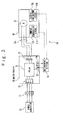
- a swinging motion reducing apparatus includes a swinging motion reducing apparatus body 10, a motor driver 20, a generator 30, and a safety unit 40.
- the swinging motion reducing apparatus body 10 includes a motor 13, a damper 15A, and a damper 15B.
- the generator 30 and the motor 13 are a 3-phase generator and a 3-phase motor, respectively.
- the motor driver 20 includes an input terminal 21, an output terminal 22, a CM terminal 23, an X1 terminal 24, and a relay 25.
- the input terminal 21 includes an R terminal, an S terminal, and a T terminal.
- the output terminal 22 includes a U terminal, a V terminal, and a W terminal.
- the relay 25 is provided between the input terminal 21 and the output terminal 22.
- the relay 25 opens and closes a connection between the R terminal and the U terminal, a connection between the S terminal and the V terminal, and a connection between the T terminal and the W terminal.
- the input terminal 21 is connected to the generator 30 via a breaker switch 31.
- the output terminal 22 is connected to a power cable 13a of the motor 13.
- the safety unit 40 includes a bimetal switch 41A provided for the damper 15A and a bimetal switch 41B provided for the damper 15B.
- the bimetal switches 41A and 41B are in a close state initially, and monitor temperatures of the dampers 15A and 15B, respectively.
- the bimetal switch 41A opens to set an OFF state when a temperature of the damper 15A increase to a temperature equal to or higher than a predetermined temperature.
- the bimetal switch 41B opens to set an OFF state when the temperature of the damper 15B increase to a temperature equal to or higher than a predetermined temperature.
- the CM terminal 23 is connected to the X1 terminal 24 via the bimetal switches 41A and 41B.
- the connection between the CM terminal 23 and the X1 terminal 24 is in an ON state (a conduction state) when both of the bimetal switches 41A and 41B close, and the connection between the CM terminal 23 and the X1 terminal 24 is in an OFF state (a non-conduction state) when at least one of the bimetal switches 41A and 41B opens.
- the relay 25 turns the connection between the input terminal 21 and the output terminal 22 to be in the ON state (closes the connection between the input terminal 21 and the output terminal 22) when the connection between the CM terminal 23 and the X1 terminal 24 is in the ON state. Also, the relay 25 turns the connection between the input terminal 21 and the output terminal 22 to be in the OFF state (opens the connection between the input terminal 21 and the output terminal 22) when the connection between the CM terminal 23 and the X1 terminal 24 is in the OFF state.
- the motor driver 20 supplies a drive power to the motor 13 when the relay 25 keeps the connection between the input terminal 21 and the output terminal 22 in the ON state, and stops the supply of the drive power when the relay 25 turns the connection between the input terminal 21 and the output terminal 22 to be in the OFF state.
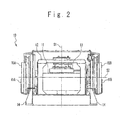
- the swinging motion reducing apparatus body 10 includes the flywheel 11, the gimbal mechanism 12, the motor 13, a gimbal mechanism support section 14, and the dampers 15A and 15B.
- the gimbal mechanism 12 supports the flywheel 11 so that the flywheel 11 can rotate around a rotation axis S1.
- the motor 13 drives the flywheel 11.
- the gimbal mechanism support section 14 supports the gimbal mechanism 12 so that the gimbal mechanism 12 can swing around a swing axis S2.
- Each of the dampers 15A and 15B brakes the swinging motion of the gimbal mechanism 12 with a fluid resistance of a hydraulic oil.
- the dampers 15A and 15B are rotary dampers.
- the swing axis S2 is orthogonal to the rotation axis S1.
- the gimbal mechanism support section 14 is fixed to a hull.
- the bimetal switches 41A and 41B are attached to the outer sides of the dampers 15A and 15B, respectively.
- a principle that the swinging motion reducing apparatus according to the present embodiment reduces the swinging motion of a ship will be described by exemplifying a case that a left or right direction axis (Pitch axis) of the hull is parallel to the swing axis S2.
- the flywheel 11 is driven by the motor 13 at a high speed so as to have angular momentum H.
- a gyrotorque T1 represented by an exterior product of the angular momentum H and the angular velocity ⁇ acts to the gimbal mechanism 12, and the gimbal mechanism 12 rolls around the swing axis S2.
- a counter torque T2 acts to the hull via the gimbal mechanism support section 14.
- the counter torque T2 is represented by an exterior product of the angular momentum H and the angular velocity ⁇ . Because the counter torque T2 acts to a direction opposite to the roll direction of the hull, the rolling motion in the roll direction of the hull is reduced.
- the swinging motion reducing apparatus when used under an overload circumstance such as a case where a ship having the swinging motion reducing apparatus according to the present embodiment sails a high wave area, the gimbal mechanism 12 heavily swings so that the temperatures of the dampers 15A and 15B become high, and thus a seal member for sealing the hydraulic oil may be damaged. Since the gimbal mechanism 12 cannot be broken when the hydraulic oil leaks, the swinging motion reducing apparatus may be damaged.
- the bimetal switch 41A opens to turn the connection between the CM terminal 23 and the X1 terminal 24 to be in the OFF state. Then, since the relay 25 turns the connection between the input terminal 21 and the output terminal 22 to be in the OFF state, the motor driver 20 automatically stops the supply of the drive power. Also, when the temperature of the damper 15B increases the predetermined temperature or more, the motor driver 20 automatically stops the supply of the drive power in the same manner as that of the damper 15A. That is, the safety unit 40 stops the supply of the drive power to the motor driver 20 when at least one of the dampers 15A and 15B exceeds the predetermined temperature. In this manner, the swinging motion reducing apparatus body 10 safely stops and the dampers 15A and 15B can be prevented from being damaged.
- the temperatures of the damper 15A or 15B becomes high.
- the present embodiment prevents the swinging motion reducing apparatus from continuing to operate under the condition of occurrence of the failure of the damper 15A or 15B. Accordingly, the damage of the damper 15A or 15B can be prevented and the damage of the swinging motion reducing apparatus body 10 is prevented.
- the damper 15A or 15B cannot release the heat to circumference, and accordingly a braking performance of the damper 15A or 15B deteriorates.
- the swinging motion reducing apparatus body 10 may be damaged. According to the present embodiment, since the swinging motion reducing apparatus is stopped in the case of a high atmosphere temperature, the damage of the swinging motion reducing apparatus body 10 can be prevented.
- the bimetal switches 41A and 41B are respectively arranged on the outer sides of the dampers 15A and 15B, the swinging motion reducing apparatus can be easily assembled. Meanwhile, the bimetal switches 41A and 41B may be arranged in the dampers 15A and 15B, respectively.
- the swinging motion reducing apparatus for a ship according to a second embodiment of the present invention will be described.
- the swinging motion reducing apparatus according to the second embodiment of the present invention is configured by replacing the safety unit 40 in the first embodiment with a safety unit 50.
- the safety unit 50 includes temperature sensors 51A and 51B such as a thermocouple or a thermistor, and a determining section 52.
- the temperature sensors 51A and 51B are provided for the dampers 15A and 15B, respectively.
- the temperature sensor 51A monitors a temperature of the damper 15A and outputs a signal indicating the temperature of the damper 15A to the determining section 52.
- the temperature sensor 51B monitors a temperature of the damper 15B and outputs a signal indicating the temperature of the damper 15B to the determining section 52.
- the determining section 52 is connected to the CM terminal 23 and the X1 terminal 24, respectively.
- the determining section 52 determines whether or not the temperatures indicated by the signals sent from the temperature sensors 51A and 51B are higher than a predetermined temperature. When both of the signal sent from the temperature sensor 51A and the signal sent from the temperature sensor 51B indicate a temperature lower than the predetermined temperature, the determining section 52 turns the connection between the CM terminal 23 and the X1 terminal 24 to be in the ON state.
- the determining section 52 turns the connection between the CM terminal 23 and the X1 terminal 24 to be in the OFF state. Accordingly, when at least one of the dampers 15A and 15B exceeds the predetermined temperature, the safety unit 50 stops the supply of the drive power to the motor 13.
- the temperature sensors 51A and 51B are arranged on the outer sides of the dampers 15A and 15B, the swinging motion reducing apparatus can be easily assembled. Meanwhile, the temperature sensors 51A and 51B may be arranged in the dampers 15A and 15B, respectively.
- the generator 30 and the motor 13 may be a single-phase generator and a single-phase motor, respectively.
- the dampers 15A and 15B may be a frictional damper, a linear damper, or a hydraulic pump.
Landscapes
- Chemical & Material Sciences (AREA)
- Engineering & Computer Science (AREA)
- Combustion & Propulsion (AREA)
- Mechanical Engineering (AREA)
- Ocean & Marine Engineering (AREA)
- Vibration Prevention Devices (AREA)
- Fluid-Pressure Circuits (AREA)
- Connection Of Motors, Electrical Generators, Mechanical Devices, And The Like (AREA)
Abstract
Description
- The present invention relates to an apparatus for reducing a swinging motion of a ship such as a rolling motion, a pitching motion and a yawing motion.
- Japanese Patent No.
3,556,857 - An object of the present invention is to prevent a swinging motion reducing apparatus for a ship from being damaged.
- In an aspect of the present invention, a swing motion reducing apparatus for a ship includes a flywheel, a gimbal mechanism configured to rotatably support the flywheel, a motor configured to rotate the flywheel based on a drive power to be supplied; and a motor driver configured to supply the drive power to the motor. A damper section is configured to brake a swing motion of the gimbal mechanism. A safety unit controls the motor driver to stop the supply of the drive power to the motor when a temperature of the damper section is equal to or higher than a predetermined temperature.
- According to the present invention, damage of a swinging motion reducing apparatus for a ship is prevented.
-
-
FIG. 1 is a diagram schematically showing a swinging motion reducing apparatus for a ship according to a first embodiment of the present invention; -
FIG. 2 is a cross-section view of the swinging motion reducing apparatus body; and -
FIG. 3 is a diagram schematically showing the swinging motion reducing apparatus according to a second embodiment of the present invention. - Hereinafter, a swinging motion reducing apparatus for a ship according to the present invention will be described with reference to the attached drawings.
- As shown in
FIG. 1 , a swinging motion reducing apparatus according to a first embodiment of the present invention includes a swinging motion reducingapparatus body 10, amotor driver 20, agenerator 30, and asafety unit 40. The swinging motion reducingapparatus body 10 includes amotor 13, adamper 15A, and adamper 15B. Thegenerator 30 and themotor 13 are a 3-phase generator and a 3-phase motor, respectively. Themotor driver 20 includes aninput terminal 21, anoutput terminal 22, aCM terminal 23, anX1 terminal 24, and arelay 25. Theinput terminal 21 includes an R terminal, an S terminal, and a T terminal. Theoutput terminal 22 includes a U terminal, a V terminal, and a W terminal. Therelay 25 is provided between theinput terminal 21 and theoutput terminal 22. Therelay 25 opens and closes a connection between the R terminal and the U terminal, a connection between the S terminal and the V terminal, and a connection between the T terminal and the W terminal. Theinput terminal 21 is connected to thegenerator 30 via abreaker switch 31. Theoutput terminal 22 is connected to apower cable 13a of themotor 13. - The
safety unit 40 includes abimetal switch 41A provided for thedamper 15A and abimetal switch 41B provided for thedamper 15B. Thebimetal switches dampers bimetal switch 41A opens to set an OFF state when a temperature of thedamper 15A increase to a temperature equal to or higher than a predetermined temperature. Thebimetal switch 41B opens to set an OFF state when the temperature of thedamper 15B increase to a temperature equal to or higher than a predetermined temperature. TheCM terminal 23 is connected to theX1 terminal 24 via thebimetal switches bimetal switches CM terminal 23 and theX1 terminal 24 is in an ON state (a conduction state) when both of thebimetal switches CM terminal 23 and theX1 terminal 24 is in an OFF state (a non-conduction state) when at least one of thebimetal switches - The
relay 25 turns the connection between theinput terminal 21 and theoutput terminal 22 to be in the ON state (closes the connection between theinput terminal 21 and the output terminal 22) when the connection between theCM terminal 23 and theX1 terminal 24 is in the ON state. Also, therelay 25 turns the connection between theinput terminal 21 and theoutput terminal 22 to be in the OFF state (opens the connection between theinput terminal 21 and the output terminal 22) when the connection between theCM terminal 23 and theX1 terminal 24 is in the OFF state. - The
motor driver 20 supplies a drive power to themotor 13 when therelay 25 keeps the connection between theinput terminal 21 and theoutput terminal 22 in the ON state, and stops the supply of the drive power when therelay 25 turns the connection between theinput terminal 21 and theoutput terminal 22 to be in the OFF state. - As shown in
FIG. 2 , the swinging motion reducingapparatus body 10 includes theflywheel 11, thegimbal mechanism 12, themotor 13, a gimbalmechanism support section 14, and thedampers gimbal mechanism 12 supports theflywheel 11 so that theflywheel 11 can rotate around a rotation axis S1. Themotor 13 drives theflywheel 11. The gimbalmechanism support section 14 supports thegimbal mechanism 12 so that thegimbal mechanism 12 can swing around a swing axis S2. Each of thedampers gimbal mechanism 12 with a fluid resistance of a hydraulic oil. For example, thedampers mechanism support section 14 is fixed to a hull. Thebimetal switches dampers - A principle that the swinging motion reducing apparatus according to the present embodiment reduces the swinging motion of a ship will be described by exemplifying a case that a left or right direction axis (Pitch axis) of the hull is parallel to the swing axis S2. The
flywheel 11 is driven by themotor 13 at a high speed so as to have angular momentum H. When the hull receives a wave in a direction of a roll axis to roll at an angular velocity Q, a gyrotorque T1 represented by an exterior product of the angular momentum H and the angular velocity Ω acts to thegimbal mechanism 12, and thegimbal mechanism 12 rolls around the swing axis S2. At this time, since theflywheel 11 works to maintain the angular momentum H, a counter torque T2 acts to the hull via the gimbalmechanism support section 14. When an angular velocity of the swinging motion of thegimbal mechanism 12 is ω, the counter torque T2 is represented by an exterior product of the angular momentum H and the angular velocity ω. Because the counter torque T2 acts to a direction opposite to the roll direction of the hull, the rolling motion in the roll direction of the hull is reduced. - For example, when the swinging motion reducing apparatus is used under an overload circumstance such as a case where a ship having the swinging motion reducing apparatus according to the present embodiment sails a high wave area, the
gimbal mechanism 12 heavily swings so that the temperatures of thedampers gimbal mechanism 12 cannot be broken when the hydraulic oil leaks, the swinging motion reducing apparatus may be damaged. - Referring to
FIG. 1 , when the temperature of thedamper 15A increases the predetermined temperature or more, thebimetal switch 41A opens to turn the connection between theCM terminal 23 and theX1 terminal 24 to be in the OFF state. Then, since therelay 25 turns the connection between theinput terminal 21 and theoutput terminal 22 to be in the OFF state, themotor driver 20 automatically stops the supply of the drive power. Also, when the temperature of thedamper 15B increases the predetermined temperature or more, themotor driver 20 automatically stops the supply of the drive power in the same manner as that of thedamper 15A. That is, thesafety unit 40 stops the supply of the drive power to themotor driver 20 when at least one of thedampers apparatus body 10 safely stops and thedampers - Additionally, in case of occurrence of a failure of the
damper damper damper damper apparatus body 10 is prevented. - Moreover, when an atmosphere temperature around the swinging motion reducing
apparatus body 10 is high, thedamper damper damper apparatus body 10 may be damaged. According to the present embodiment, since the swinging motion reducing apparatus is stopped in the case of a high atmosphere temperature, the damage of the swinging motion reducingapparatus body 10 can be prevented. - Since the
bimetal switches dampers bimetal switches dampers - Referring to
FIG. 3 , the swinging motion reducing apparatus for a ship according to a second embodiment of the present invention will be described. The swinging motion reducing apparatus according to the second embodiment of the present invention is configured by replacing thesafety unit 40 in the first embodiment with asafety unit 50. Thesafety unit 50 includestemperature sensors section 52. Thetemperature sensors dampers temperature sensor 51A monitors a temperature of thedamper 15A and outputs a signal indicating the temperature of thedamper 15A to the determiningsection 52. Thetemperature sensor 51B monitors a temperature of thedamper 15B and outputs a signal indicating the temperature of thedamper 15B to the determiningsection 52. The determiningsection 52 is connected to theCM terminal 23 and theX1 terminal 24, respectively. The determiningsection 52 determines whether or not the temperatures indicated by the signals sent from thetemperature sensors temperature sensor 51A and the signal sent from thetemperature sensor 51B indicate a temperature lower than the predetermined temperature, the determiningsection 52 turns the connection between theCM terminal 23 and theX1 terminal 24 to be in the ON state. When the temperature indicated by at least one of the signal sent from thetemperature sensor 51A and the signal sent from thetemperature sensor 51B exceeds the predetermined temperature, the determiningsection 52 turns the connection between theCM terminal 23 and theX1 terminal 24 to be in the OFF state. Accordingly, when at least one of thedampers safety unit 50 stops the supply of the drive power to themotor 13. - When the
temperature sensors dampers temperature sensors dampers - In the above-mentioned respective embodiments, the
generator 30 and themotor 13 may be a single-phase generator and a single-phase motor, respectively. In addition, thedampers
Claims (5)
- A swing motion reducing apparatus for a ship comprising:a flywheel;a gimbal mechanism configured to rotatably support said flywheel;a motor configured to rotate said flywheel based on a drive power to be supplied;a motor driver configured to supply the drive power to said motor;a damper section configured to brake a swing motion of said gimbal mechanism; anda safety unit configured to control said motor driver to stop the supply of the drive power to said motor when a temperature of said damper section is equal to or higher than a predetermined temperature.
- The swing motion reducing apparatus according to claim 1, wherein said motor driver comprises first and second terminals,
wherein said safety unit comprises a path from said first terminal to said second terminal, and
said motor driver supplies the drive power to said motor when said path is in an ON state, and stops the supply of the drive power to said motor when said path is in an OFF state. - The swing motion reducing apparatus according to claim 2, wherein said damper section comprises a first damper configured to brake the swing motion of said gimbal mechanism,
said safety unit comprises a first bimetal switch provided for said first damper in said path, and
said first bimetal switch sets said path to the ON state when the temperature of said first damper lower than the predetermined temperature and sets said path to the OFF state when the temperature of said first damper equal to or higher than the predetermined temperature. - The swing motion reducing apparatus according to claim 3, wherein said damper section comprises a second damper configured to brake the swing motion of said gimbal mechanism,
wherein said safety unit further comprises a second bimetal switch provided for said second damper in said path and connected with said first bimetal switch in series, and
said second bimetal switch sets said path to the ON state when the temperature of said second damper lower than the predetermined temperature and sets said path to the OFF state when the temperature of said second damper equal to or higher than the predetermined temperature. - The swing motion reducing apparatus according to claim 2, wherein said damper section comprises first and second dampers, each of which brakes the swing motion of said gimbal mechanism;
said safety unit further comprises:first and second temperature sensors provided for said first and second dampers to detect temperatures of said first and second dampers, respectively; anda determining section sets said path to the ON state, when both of temperatures detected by said first and second temperature sensors are lower than the predetermined temperature, and sets said path to the OFF state, when at least one of temperatures detected by said first and second temperature sensors is equal to or higher than the predetermined temperature.
Applications Claiming Priority (1)
| Application Number | Priority Date | Filing Date | Title |
|---|---|---|---|
| JP2009103158A JP4782216B2 (en) | 2009-04-21 | 2009-04-21 | Ship vibration reduction device |
Publications (3)
| Publication Number | Publication Date |
|---|---|
| EP2243697A2 true EP2243697A2 (en) | 2010-10-27 |
| EP2243697A3 EP2243697A3 (en) | 2011-11-30 |
| EP2243697B1 EP2243697B1 (en) | 2013-03-13 |
Family
ID=42270174
Family Applications (1)
| Application Number | Title | Priority Date | Filing Date |
|---|---|---|---|
| EP10152137A Active EP2243697B1 (en) | 2009-04-21 | 2010-01-29 | Swing motion reducing apparatus for ship |
Country Status (7)
| Country | Link |
|---|---|
| US (1) | US20110030604A1 (en) |
| EP (1) | EP2243697B1 (en) |
| JP (1) | JP4782216B2 (en) |
| AU (1) | AU2010200361B2 (en) |
| ES (1) | ES2412269T3 (en) |
| NZ (1) | NZ583020A (en) |
| TW (1) | TWI383920B (en) |
Families Citing this family (2)
| Publication number | Priority date | Publication date | Assignee | Title |
|---|---|---|---|---|
| US8776709B2 (en) | 2012-06-22 | 2014-07-15 | Honeywell International Inc. | Apparatus and method for watercraft stabilization |
| JP5646066B1 (en) | 2013-03-04 | 2014-12-24 | 三菱重工業株式会社 | Anti-vibration device and ship using the same |
Citations (1)
| Publication number | Priority date | Publication date | Assignee | Title |
|---|---|---|---|---|
| JP3556857B2 (en) | 1999-04-21 | 2004-08-25 | 三菱重工業株式会社 | Anti-rolling device with safety mechanism |
Family Cites Families (12)
| Publication number | Priority date | Publication date | Assignee | Title |
|---|---|---|---|---|
| US1183530A (en) * | 1910-01-04 | 1916-05-16 | Louis Brennan | Means for imparting stability to unstable bodies. |
| US3576134A (en) * | 1968-02-19 | 1971-04-27 | Tetra Tech | Gyroscopic stabilizer having an adjustable spring |
| DE1906836C3 (en) * | 1969-02-12 | 1975-01-02 | Siemens Ag, 1000 Berlin Und 8000 Muenchen | Adaptive control device for a control loop |
| US3567134A (en) * | 1969-09-09 | 1971-03-02 | Rubbermaid Inc | Dual purpose hose |
| US5628267A (en) * | 1993-11-01 | 1997-05-13 | Mitsubishi Jukogyo Kabushiki Kaisha | Oscillation suppression device and ship provided with the same |
| JPH10244990A (en) * | 1997-03-05 | 1998-09-14 | Mitsubishi Heavy Ind Ltd | Gyro type anti-rocking device |
| JP2000337433A (en) * | 1999-05-28 | 2000-12-05 | Mitsubishi Heavy Ind Ltd | Cmg anti-rocking machine |
| JP3486405B2 (en) * | 2001-08-10 | 2004-01-13 | 三菱重工業株式会社 | Rocking device |
| US6973847B2 (en) * | 2003-06-04 | 2005-12-13 | Gearloose Engineering, Inc. | Gyroscopic roll stabilizer for boats |
| US20090114136A1 (en) * | 2003-09-19 | 2009-05-07 | Seagyro Pty Ltd | Vessel Stabilization Apparatus and Method |
| US7240630B2 (en) * | 2003-10-08 | 2007-07-10 | Marine Motion Control, Llc | Gyrostabilizer for small boats |
| WO2006022847A2 (en) * | 2004-03-25 | 2006-03-02 | Exxonmobil Upstream Research Company | Hydrogyro ship stabilizer and method for stabilizing a vessel |
-
2009
- 2009-04-21 JP JP2009103158A patent/JP4782216B2/en active Active
-
2010
- 2010-01-29 TW TW099102749A patent/TWI383920B/en active
- 2010-01-29 EP EP10152137A patent/EP2243697B1/en active Active
- 2010-01-29 ES ES10152137T patent/ES2412269T3/en active Active
- 2010-01-29 US US12/696,687 patent/US20110030604A1/en not_active Abandoned
- 2010-02-01 NZ NZ583020A patent/NZ583020A/en unknown
- 2010-02-01 AU AU2010200361A patent/AU2010200361B2/en active Active
Patent Citations (1)
| Publication number | Priority date | Publication date | Assignee | Title |
|---|---|---|---|---|
| JP3556857B2 (en) | 1999-04-21 | 2004-08-25 | 三菱重工業株式会社 | Anti-rolling device with safety mechanism |
Also Published As
| Publication number | Publication date |
|---|---|
| EP2243697B1 (en) | 2013-03-13 |
| AU2010200361B2 (en) | 2011-04-21 |
| ES2412269T3 (en) | 2013-07-10 |
| EP2243697A3 (en) | 2011-11-30 |
| US20110030604A1 (en) | 2011-02-10 |
| TW201040075A (en) | 2010-11-16 |
| NZ583020A (en) | 2011-06-30 |
| TWI383920B (en) | 2013-02-01 |
| JP2010256042A (en) | 2010-11-11 |
| AU2010200361A1 (en) | 2010-11-04 |
| JP4782216B2 (en) | 2011-09-28 |
Similar Documents
| Publication | Publication Date | Title |
|---|---|---|
| JP5644821B2 (en) | Inverted motorcycle and control method thereof | |
| EP2527230A1 (en) | Control device of electrohydraulic power steering apparatus | |
| US8212511B2 (en) | Method and apparatus for limiting torque in an electric drive motor | |
| JP2015533999A (en) | Wind turbine yaw control system | |
| US8255102B2 (en) | Steering unit for a steer-by-wire ship's control system and method for operating the steering unit | |
| EP2243697B1 (en) | Swing motion reducing apparatus for ship | |
| KR102180379B1 (en) | Propulsion and Braking system using clutch | |
| WO2008059731A1 (en) | Vehicle steering device | |
| JP2012055981A (en) | Robot control device and robot control method | |
| JP5296942B1 (en) | Control device | |
| US11002341B2 (en) | Drive device and method for speed limitation | |
| CN111478646A (en) | Temperature protection method and system for electric vehicle motor system, electric vehicle and storage medium | |
| JP5218938B2 (en) | Ship motor drive system | |
| JP3556857B2 (en) | Anti-rolling device with safety mechanism | |
| EP1580119B1 (en) | Improved power plant | |
| KR20030087256A (en) | A fail safety apparatus of electric motor type power steering apparatus | |
| JP4534882B2 (en) | Power limit method for hybrid vehicle | |
| US10753234B2 (en) | Turning apparatus and control method for turning apparatus | |
| JP5309812B2 (en) | Motor control device and motor control method | |
| JPH04166681A (en) | Protective device of electric servo-motor | |
| US20250153767A1 (en) | Control device, control method, and control system | |
| JPH0974781A (en) | Protective device for regenerative braking circuit of servo control apparatus | |
| JP5261107B2 (en) | Motor drive device, motor drive system, and electric vehicle | |
| KR20190069002A (en) | Apparatus and method for controlling vehicle | |
| KR20250074933A (en) | Seamless embedded apparatus and method capable of redundancy control of actuator in autonomous vehicle |
Legal Events
| Date | Code | Title | Description |
|---|---|---|---|
| PUAI | Public reference made under article 153(3) epc to a published international application that has entered the european phase |
Free format text: ORIGINAL CODE: 0009012 |
|
| AK | Designated contracting states |
Kind code of ref document: A2 Designated state(s): AT BE BG CH CY CZ DE DK EE ES FI FR GB GR HR HU IE IS IT LI LT LU LV MC MK MT NL NO PL PT RO SE SI SK SM TR |
|
| AX | Request for extension of the european patent |
Extension state: AL BA RS |
|
| PUAL | Search report despatched |
Free format text: ORIGINAL CODE: 0009013 |
|
| AK | Designated contracting states |
Kind code of ref document: A3 Designated state(s): AT BE BG CH CY CZ DE DK EE ES FI FR GB GR HR HU IE IS IT LI LT LU LV MC MK MT NL NO PL PT RO SE SI SK SM TR |
|
| AX | Request for extension of the european patent |
Extension state: AL BA RS |
|
| RIC1 | Information provided on ipc code assigned before grant |
Ipc: B63B 39/04 20060101AFI20111027BHEP |
|
| 17P | Request for examination filed |
Effective date: 20120521 |
|
| GRAP | Despatch of communication of intention to grant a patent |
Free format text: ORIGINAL CODE: EPIDOSNIGR1 |
|
| GRAS | Grant fee paid |
Free format text: ORIGINAL CODE: EPIDOSNIGR3 |
|
| GRAA | (expected) grant |
Free format text: ORIGINAL CODE: 0009210 |
|
| AK | Designated contracting states |
Kind code of ref document: B1 Designated state(s): AT BE BG CH CY CZ DE DK EE ES FI FR GB GR HR HU IE IS IT LI LT LU LV MC MK MT NL NO PL PT RO SE SI SK SM TR |
|
| REG | Reference to a national code |
Ref country code: GB Ref legal event code: FG4D |
|
| REG | Reference to a national code |
Ref country code: CH Ref legal event code: EP Ref country code: AT Ref legal event code: REF Ref document number: 600633 Country of ref document: AT Kind code of ref document: T Effective date: 20130315 |
|
| REG | Reference to a national code |
Ref country code: IE Ref legal event code: FG4D |
|
| REG | Reference to a national code |
Ref country code: DE Ref legal event code: R096 Ref document number: 602010005369 Country of ref document: DE Effective date: 20130508 |
|
| REG | Reference to a national code |
Ref country code: SE Ref legal event code: TRGR |
|
| REG | Reference to a national code |
Ref country code: ES Ref legal event code: FG2A Ref document number: 2412269 Country of ref document: ES Kind code of ref document: T3 Effective date: 20130710 |
|
| PG25 | Lapsed in a contracting state [announced via postgrant information from national office to epo] |
Ref country code: NO Free format text: LAPSE BECAUSE OF FAILURE TO SUBMIT A TRANSLATION OF THE DESCRIPTION OR TO PAY THE FEE WITHIN THE PRESCRIBED TIME-LIMIT Effective date: 20130613 Ref country code: BG Free format text: LAPSE BECAUSE OF FAILURE TO SUBMIT A TRANSLATION OF THE DESCRIPTION OR TO PAY THE FEE WITHIN THE PRESCRIBED TIME-LIMIT Effective date: 20130613 Ref country code: LT Free format text: LAPSE BECAUSE OF FAILURE TO SUBMIT A TRANSLATION OF THE DESCRIPTION OR TO PAY THE FEE WITHIN THE PRESCRIBED TIME-LIMIT Effective date: 20130313 |
|
| REG | Reference to a national code |
Ref country code: NL Ref legal event code: T3 |
|
| REG | Reference to a national code |
Ref country code: AT Ref legal event code: MK05 Ref document number: 600633 Country of ref document: AT Kind code of ref document: T Effective date: 20130313 |
|
| REG | Reference to a national code |
Ref country code: LT Ref legal event code: MG4D |
|
| PG25 | Lapsed in a contracting state [announced via postgrant information from national office to epo] |
Ref country code: SI Free format text: LAPSE BECAUSE OF FAILURE TO SUBMIT A TRANSLATION OF THE DESCRIPTION OR TO PAY THE FEE WITHIN THE PRESCRIBED TIME-LIMIT Effective date: 20130313 Ref country code: GR Free format text: LAPSE BECAUSE OF FAILURE TO SUBMIT A TRANSLATION OF THE DESCRIPTION OR TO PAY THE FEE WITHIN THE PRESCRIBED TIME-LIMIT Effective date: 20130614 Ref country code: FI Free format text: LAPSE BECAUSE OF FAILURE TO SUBMIT A TRANSLATION OF THE DESCRIPTION OR TO PAY THE FEE WITHIN THE PRESCRIBED TIME-LIMIT Effective date: 20130313 Ref country code: LV Free format text: LAPSE BECAUSE OF FAILURE TO SUBMIT A TRANSLATION OF THE DESCRIPTION OR TO PAY THE FEE WITHIN THE PRESCRIBED TIME-LIMIT Effective date: 20130313 |
|
| PG25 | Lapsed in a contracting state [announced via postgrant information from national office to epo] |
Ref country code: BE Free format text: LAPSE BECAUSE OF FAILURE TO SUBMIT A TRANSLATION OF THE DESCRIPTION OR TO PAY THE FEE WITHIN THE PRESCRIBED TIME-LIMIT Effective date: 20130313 Ref country code: HR Free format text: LAPSE BECAUSE OF FAILURE TO SUBMIT A TRANSLATION OF THE DESCRIPTION OR TO PAY THE FEE WITHIN THE PRESCRIBED TIME-LIMIT Effective date: 20130313 |
|
| PG25 | Lapsed in a contracting state [announced via postgrant information from national office to epo] |
Ref country code: RO Free format text: LAPSE BECAUSE OF FAILURE TO SUBMIT A TRANSLATION OF THE DESCRIPTION OR TO PAY THE FEE WITHIN THE PRESCRIBED TIME-LIMIT Effective date: 20130313 Ref country code: IS Free format text: LAPSE BECAUSE OF FAILURE TO SUBMIT A TRANSLATION OF THE DESCRIPTION OR TO PAY THE FEE WITHIN THE PRESCRIBED TIME-LIMIT Effective date: 20130713 Ref country code: SK Free format text: LAPSE BECAUSE OF FAILURE TO SUBMIT A TRANSLATION OF THE DESCRIPTION OR TO PAY THE FEE WITHIN THE PRESCRIBED TIME-LIMIT Effective date: 20130313 Ref country code: CZ Free format text: LAPSE BECAUSE OF FAILURE TO SUBMIT A TRANSLATION OF THE DESCRIPTION OR TO PAY THE FEE WITHIN THE PRESCRIBED TIME-LIMIT Effective date: 20130313 Ref country code: AT Free format text: LAPSE BECAUSE OF FAILURE TO SUBMIT A TRANSLATION OF THE DESCRIPTION OR TO PAY THE FEE WITHIN THE PRESCRIBED TIME-LIMIT Effective date: 20130313 Ref country code: PT Free format text: LAPSE BECAUSE OF FAILURE TO SUBMIT A TRANSLATION OF THE DESCRIPTION OR TO PAY THE FEE WITHIN THE PRESCRIBED TIME-LIMIT Effective date: 20130715 Ref country code: EE Free format text: LAPSE BECAUSE OF FAILURE TO SUBMIT A TRANSLATION OF THE DESCRIPTION OR TO PAY THE FEE WITHIN THE PRESCRIBED TIME-LIMIT Effective date: 20130313 |
|
| PG25 | Lapsed in a contracting state [announced via postgrant information from national office to epo] |
Ref country code: PL Free format text: LAPSE BECAUSE OF FAILURE TO SUBMIT A TRANSLATION OF THE DESCRIPTION OR TO PAY THE FEE WITHIN THE PRESCRIBED TIME-LIMIT Effective date: 20130313 |
|
| PLBE | No opposition filed within time limit |
Free format text: ORIGINAL CODE: 0009261 |
|
| STAA | Information on the status of an ep patent application or granted ep patent |
Free format text: STATUS: NO OPPOSITION FILED WITHIN TIME LIMIT |
|
| PG25 | Lapsed in a contracting state [announced via postgrant information from national office to epo] |
Ref country code: DK Free format text: LAPSE BECAUSE OF FAILURE TO SUBMIT A TRANSLATION OF THE DESCRIPTION OR TO PAY THE FEE WITHIN THE PRESCRIBED TIME-LIMIT Effective date: 20130313 |
|
| 26N | No opposition filed |
Effective date: 20131216 |
|
| REG | Reference to a national code |
Ref country code: DE Ref legal event code: R097 Ref document number: 602010005369 Country of ref document: DE Effective date: 20131216 |
|
| PG25 | Lapsed in a contracting state [announced via postgrant information from national office to epo] |
Ref country code: MC Free format text: LAPSE BECAUSE OF FAILURE TO SUBMIT A TRANSLATION OF THE DESCRIPTION OR TO PAY THE FEE WITHIN THE PRESCRIBED TIME-LIMIT Effective date: 20130313 Ref country code: LU Free format text: LAPSE BECAUSE OF FAILURE TO SUBMIT A TRANSLATION OF THE DESCRIPTION OR TO PAY THE FEE WITHIN THE PRESCRIBED TIME-LIMIT Effective date: 20140129 |
|
| REG | Reference to a national code |
Ref country code: CH Ref legal event code: PL |
|
| PG25 | Lapsed in a contracting state [announced via postgrant information from national office to epo] |
Ref country code: LI Free format text: LAPSE BECAUSE OF NON-PAYMENT OF DUE FEES Effective date: 20140131 Ref country code: CH Free format text: LAPSE BECAUSE OF NON-PAYMENT OF DUE FEES Effective date: 20140131 |
|
| REG | Reference to a national code |
Ref country code: IE Ref legal event code: MM4A |
|
| PG25 | Lapsed in a contracting state [announced via postgrant information from national office to epo] |
Ref country code: IE Free format text: LAPSE BECAUSE OF NON-PAYMENT OF DUE FEES Effective date: 20140129 |
|
| REG | Reference to a national code |
Ref country code: FR Ref legal event code: PLFP Year of fee payment: 7 |
|
| PG25 | Lapsed in a contracting state [announced via postgrant information from national office to epo] |
Ref country code: MT Free format text: LAPSE BECAUSE OF FAILURE TO SUBMIT A TRANSLATION OF THE DESCRIPTION OR TO PAY THE FEE WITHIN THE PRESCRIBED TIME-LIMIT Effective date: 20130313 |
|
| PG25 | Lapsed in a contracting state [announced via postgrant information from national office to epo] |
Ref country code: SM Free format text: LAPSE BECAUSE OF FAILURE TO SUBMIT A TRANSLATION OF THE DESCRIPTION OR TO PAY THE FEE WITHIN THE PRESCRIBED TIME-LIMIT Effective date: 20130313 |
|
| PG25 | Lapsed in a contracting state [announced via postgrant information from national office to epo] |
Ref country code: CY Free format text: LAPSE BECAUSE OF FAILURE TO SUBMIT A TRANSLATION OF THE DESCRIPTION OR TO PAY THE FEE WITHIN THE PRESCRIBED TIME-LIMIT Effective date: 20130313 |
|
| PG25 | Lapsed in a contracting state [announced via postgrant information from national office to epo] |
Ref country code: HU Free format text: LAPSE BECAUSE OF FAILURE TO SUBMIT A TRANSLATION OF THE DESCRIPTION OR TO PAY THE FEE WITHIN THE PRESCRIBED TIME-LIMIT; INVALID AB INITIO Effective date: 20100129 Ref country code: TR Free format text: LAPSE BECAUSE OF FAILURE TO SUBMIT A TRANSLATION OF THE DESCRIPTION OR TO PAY THE FEE WITHIN THE PRESCRIBED TIME-LIMIT Effective date: 20130313 |
|
| REG | Reference to a national code |
Ref country code: DE Ref legal event code: R082 Ref document number: 602010005369 Country of ref document: DE Representative=s name: KOHLER SCHMID MOEBUS PATENTANWAELTE PARTNERSCH, DE Ref country code: DE Ref legal event code: R081 Ref document number: 602010005369 Country of ref document: DE Owner name: TOHMEI INDUSTRIES CO., LTD., CHITA-SHI, JP Free format text: FORMER OWNER: MITSUBISHI HEAVY INDUSTRIES, LTD., TOKYO, JP |
|
| REG | Reference to a national code |
Ref country code: NL Ref legal event code: PD Owner name: TOHMEI INDUSTRIES CO., LTD.; JP Free format text: DETAILS ASSIGNMENT: VERANDERING VAN EIGENAAR(S), OVERDRACHT; FORMER OWNER NAME: MITSUBISHI HEAVY INDUSTRIES, LTD. Effective date: 20160926 |
|
| REG | Reference to a national code |
Ref country code: ES Ref legal event code: PC2A Owner name: TOHMEI INDUSTRIES CO. LTD. Effective date: 20161110 |
|
| REG | Reference to a national code |
Ref country code: FR Ref legal event code: PLFP Year of fee payment: 8 |
|
| REG | Reference to a national code |
Ref country code: GB Ref legal event code: 732E Free format text: REGISTERED BETWEEN 20161124 AND 20161130 |
|
| REG | Reference to a national code |
Ref country code: FR Ref legal event code: TP Owner name: TOHMEI INDUSTRIES CO., LTD., JP Effective date: 20161222 |
|
| REG | Reference to a national code |
Ref country code: FR Ref legal event code: PLFP Year of fee payment: 9 |
|
| PG25 | Lapsed in a contracting state [announced via postgrant information from national office to epo] |
Ref country code: MK Free format text: LAPSE BECAUSE OF FAILURE TO SUBMIT A TRANSLATION OF THE DESCRIPTION OR TO PAY THE FEE WITHIN THE PRESCRIBED TIME-LIMIT Effective date: 20130313 |
|
| P01 | Opt-out of the competence of the unified patent court (upc) registered |
Effective date: 20230509 |
|
| P02 | Opt-out of the competence of the unified patent court (upc) changed |
Effective date: 20230515 |
|
| P02 | Opt-out of the competence of the unified patent court (upc) changed |
Effective date: 20230525 |
|
| PGFP | Annual fee paid to national office [announced via postgrant information from national office to epo] |
Ref country code: GB Payment date: 20251211 Year of fee payment: 17 |
|
| PGFP | Annual fee paid to national office [announced via postgrant information from national office to epo] |
Ref country code: FR Payment date: 20251128 Year of fee payment: 17 Ref country code: NL Payment date: 20251215 Year of fee payment: 17 |
|
| PGFP | Annual fee paid to national office [announced via postgrant information from national office to epo] |
Ref country code: SE Payment date: 20251210 Year of fee payment: 17 |
|
| PGFP | Annual fee paid to national office [announced via postgrant information from national office to epo] |
Ref country code: ES Payment date: 20260203 Year of fee payment: 17 |
|
| PGFP | Annual fee paid to national office [announced via postgrant information from national office to epo] |
Ref country code: DE Payment date: 20251203 Year of fee payment: 17 |
|
| PGFP | Annual fee paid to national office [announced via postgrant information from national office to epo] |
Ref country code: IT Payment date: 20251219 Year of fee payment: 17 |