EP2243688A2 - Corrected forced steering for steered trailers or semi-trailers on multiple axle steering agricultural or forestry traction vehicles - Google Patents
Corrected forced steering for steered trailers or semi-trailers on multiple axle steering agricultural or forestry traction vehicles Download PDFInfo
- Publication number
- EP2243688A2 EP2243688A2 EP10152874A EP10152874A EP2243688A2 EP 2243688 A2 EP2243688 A2 EP 2243688A2 EP 10152874 A EP10152874 A EP 10152874A EP 10152874 A EP10152874 A EP 10152874A EP 2243688 A2 EP2243688 A2 EP 2243688A2
- Authority
- EP
- European Patent Office
- Prior art keywords
- steering
- trailer
- axle
- towing vehicle
- angle
- Prior art date
- Legal status (The legal status is an assumption and is not a legal conclusion. Google has not performed a legal analysis and makes no representation as to the accuracy of the status listed.)
- Granted
Links
Images


Classifications
-
- B—PERFORMING OPERATIONS; TRANSPORTING
- B62—LAND VEHICLES FOR TRAVELLING OTHERWISE THAN ON RAILS
- B62D—MOTOR VEHICLES; TRAILERS
- B62D13/00—Steering specially adapted for trailers
- B62D13/005—Steering specially adapted for trailers operated from tractor steering system
-
- B—PERFORMING OPERATIONS; TRANSPORTING
- B62—LAND VEHICLES FOR TRAVELLING OTHERWISE THAN ON RAILS
- B62D—MOTOR VEHICLES; TRAILERS
- B62D13/00—Steering specially adapted for trailers
- B62D13/02—Steering specially adapted for trailers for centrally-pivoted axles
- B62D13/025—Steering specially adapted for trailers for centrally-pivoted axles the pivoted movement being initiated by the coupling means between tractor and trailer
Definitions
- the invention relates according to the preamble of claim 1, a forced steering for a agricultural or forestry trailer / semi-trailer with at least one positively driven axle, the trailer / semi-trailer can be coupled to a multi-axis articulated agricultural or forestry towing vehicle. Furthermore, the invention relates to a agricultural or forestry trailer / semitrailer and an agricultural tractor with the corresponding forced steering and a method for performing a forced steering.
- From the DE 197 16 201 A1 is a multi-axis steering for a agricultural or forestry towing vehicle in the form of a harvesting or tractor vehicle with at least one primary controlled axis and another axis known in which a steering angle of the other axis along a progressive characteristic in response to a steering angle of the primary controlled axis is variable , As a result, different types of multi-axis steering are combined in a common steering strategy.
- the aforementioned angle is mechanically detected at the coupling point in the case of forced steering. Angle changes are transmitted by means of linkage or hydraulic lines to one or more steering axles of a trailer. Angle changes in the coupling point produce only a sufficiently accurate setpoint for the trailer steering system in the case of only front-axle towing vehicles. The trailer follows the towing vehicle here relatively true to the spur.
- a multi-axle articulated agricultural or forestry traction vehicle according to the preamble of claim 1 of the invention with a trailer or a semi-trailer has at least one forcibly steered axle, as the first axis in the direction of travel in a two-axle trailer / semitrailer, coupled to a team, so it comes in a forced steering system according to ISO 26402 when entering a curve to a contradictory steering on the trailer / semitrailer, in which the instantaneous pole of the towing vehicle and the momentanlenkpol the trailer or trailer is not on a straight line through the coupling point.
- This behavior leads to tensions or track offset of the trailer and causes damage to the terrain and at the steering device of the trailer / trailer.
- An object of the invention is to provide a forced steering, with their use, a tension and / or lane offset of the team can be reduced even in forced-steered agricultural or forestry trailers on multi-axis agricultural or forestry towing vehicles and damage to the terrain and the trailer / trailer.
- the object is achieved by the characterizing part of claim 1 and by a method for a forced steering system according to claim 14.
- the insufficient detection of the required steering angle is achieved in multi-articulated towing vehicles with the use and use of a correction angle.
- the correction angle is derived from one or more steering deflection angles of the towing vehicle, which are preferably known or alternatively detected by means of sensors, for example.
- a calculation of the correction angle can be done by means of a formula or approximately. This is the control of the trailer or semi-trailer a corrected steering angle available which allows a proper and soil-friendly steering of the trailer, especially the trailer.
- a towing vehicle having a first steerable steering axle, usually the front axle in the direction of travel, and at least one second steerable steering axle closest to the trailer, tension a longitudinal axis of the towing vehicle and a trailer / semitrailer longitudinal axis or, if used, a drawbar of the trailer a steering angle around a coupling point, which may be in the trailer hitch on.
- the steering angle is detected and applied to the forced steering to form a set point for control of the at least one positive steered axle of the trailer.
- a steering angle of the second steering axle usually this is the rear axle of the towing vehicle detected and used to form a correction angle for a correction of the control of the trailer or trailer.
- a change in the angle can also be calculated and used in each case.
- the steering deflection angle of the first and second steering axles in today's axle-steered vehicles can each be a steering deflection about the steering knuckle of the next closest wheel of the towing vehicle so that the towing vehicle forms a momentaneous steering pole.
- the correction angle and the steering angle of the second steering axle of the towing vehicle correspond and calculated accordingly simplified become, whereby a special arithmetic operation can be omitted.
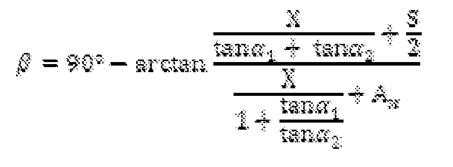
- the correction angle from the center distance between the first steering axle and the second steering axle of the towing vehicle, a steering angle of the first steerable steering axle of the towing vehicle, a distance between two stub axles of the wheels of an axle of the towing vehicle, and a clutch distance between the Coupling point and the second steering axle of the towing vehicle formed.
- ⁇ 90 ⁇ ° - arctan X tan ⁇ 1 + tan ⁇ 2 + S 2 X 1 + tan ⁇ 1 tan ⁇ 2 + A x
- X is the center distance between the first steering axle and the second steering axle of the towing vehicle
- ⁇ 2 is the steering deflection angle of the first steerable steering axle VA of the towing vehicle
- s is the distance between two stub axles of the wheels of an axle of the towing vehicle
- a x is the coupling distance between the coupling point and the second steering axle of the towing vehicle is.
- the tangent of the steering deflection angle (tan ⁇ 1 ) of the second steering axle of the towing vehicle is preferably to be calculated as equal to the quotient of the transverse distance between a Momentanlenkpol the towing vehicle and nearest to the Momentanlenkpol steering knuckle of a wheel of the second steering axle and the longitudinal distance between the Momentanlenkpol of Towing vehicle and to the Momentanlenkpol nearest steering knuckle of the wheel of the second steering axle.
- the tangent of the steering deflection angle (tan ⁇ 2 ) of the first steering axle of the towing vehicle preferably from the quotient of the transverse distance between a Momentanlenkpol the towing vehicle and nearest to the Momentanlenkpol stub axle of a wheel of the first steering axle and the longitudinal distance between the Momentanlenkpol the towing vehicle and the be determined to the Momentanlenkpol nearest steering knuckle of the wheel of the first steering axle.
- each steering axis can not usually reach 90 °, and thus the pole position in the tangent function is also not achieved.
- the actual detection of the correction angle can be achieved in one embodiment of the invention of electrical, electronic, hydraulic and / or mechanical means, in particular via a steering linkage. Additionally or alternatively, the transmission of the correction angle can also be achieved by electrical, electronic, hydraulic, mechanical means and / or a radio link to the forced steering.
- the invention is further developed in that the forced steering comprises at least one sensor which can be fastened in the region of the second steering axle of the towing vehicle, wherein a steering deflection angle of the second steering axle can be detected by means of the sensor.
- transducers can be used on steering cylinders according to the invention as sensors, as in the above DE 197 16 201 A1 in the FIGS. 8 to 12 are shown.
- the forced steering according to this invention in particular for use in conjunction with in the DE 197 16 201 A1 disclosed multi-axle steering and is suitable for a corresponding agricultural or forestry towing vehicle.
- the towing vehicle has a steering control unit by means of which the correction angle can be calculated and / or provided.
- the correction angle can be calculated in a microprocessor which is integrated in the steering control unit.
- the trailer / semitrailer may have in another embodiment, a steering control unit to the correction angle ⁇ by electric, electronic, hydraulic, mechanical means and / or a radio link is transferable.
- the correction angle can be transmitted by means of a data bus or hydraulic lines.
- control of the forced steering can be installed either in the agricultural trailer / semi-trailer or in the towing vehicle. If the control of the forced steering is part of the towing vehicle, then the wheels of the positively steered axle (s) on the trailer / semi-trailer can be articulated by means of hydraulic lines leading to the respective steering cylinders or by means of linkages in the desired forced steering angle.
- a method for forced steering, in particular for forced diversion, for a agricultural or forestry trailer / semi-trailer the trailer / semi-trailer having at least one forcibly steered axle, the trailer / semi-trailer is coupled to a agricultural or forestry towing vehicle, the towing vehicle having a first steerable steering axle (VA) and at least one second controllable steering axle (HA) closest to the trailer, a longitudinal axle of the towing vehicle and a trailer axle / trailer drawbar pivoting about a coupling point forming a steering angle ( ⁇ ) , proposed.
- VA steerable steering axle
- HA controllable steering axle
- the method comprises the following steps: detection of the steering deflection angle ( ⁇ 1 ) of at least the second steering axis (HA) of the towing vehicle, formation of a correction angle ( ⁇ ) with at least the detected steering deflection angle ( ⁇ 1 ); and calculating a corrected steering angle ( ⁇ *) with at least the steering angle ( ⁇ ) and the formed correction angle ( ⁇ ) for controlling the at least one positively driven axle.
- a corrected steering angle ( ⁇ *) with at least the steering angle ( ⁇ ) and the formed correction angle ( ⁇ ) for controlling the at least one positively driven axle.
- changes in the angles can also be detected, formed and / or calculated in each case.
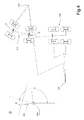
- Fig. 1 is shown by the eight wheels a known prior art Gespann according to the prior art.
- the combination consists of a towing vehicle 110 with steered front axle VA and rigid rear axle HA and a trailer 120 with positively steered front axle 122.
- Detail A shows that a longitudinal axis 111 of the towing vehicle 110 and a longitudinal axis 121 of the trailer 120 about a coupling point 130 in a trailer hitch Span steering angle ⁇ .
- the dashed rear axle HA extends at right angles to the longitudinal axis 111 of the towing vehicle 110.
- the pulling direction 112 and the longitudinal axis 111 of the towing vehicle 110 differ slightly from each other by the angle ⁇ .
- a sufficiently accurate setpoint value for the trailer steering is therefore achieved even without correction of the steering angle ⁇ at cornering. Shown is also the instantaneous steering pole 114 of towing vehicle 110.
- Fig. 2 shows the team according to Fig. 1 after further turning and detail B.
- the combination consists of a towing vehicle 210 with steered front axle VA and rigid rear axle HA and a trailer 220 with positively steered front axle 222.
- Detail A shows that a longitudinal axis 211 of the towing vehicle 210 and a longitudinal axis 221 of the trailer 220 to a coupling point 230 in one Tow hitch clamp a steering angle ⁇ .
- the dashed rear axle HA extends at right angles to the longitudinal axis of the towing vehicle 210.
- the pulling direction 212 and the longitudinal axis 211 of the towing vehicle 210 yield more than in FIG Fig. 1 shown by the angle ⁇ from each other.
- a further accurate setpoint value for the trailer steering is achieved with continued cornering even without correction of the steering angle ⁇ . Also shown is the instantaneous pole 214 of the towing vehicle 210 and a momentary pole 224 of the trailer 220.
- FIG. 3 to FIG. 5 each show a towing vehicle 310, 410 and 510 with steered rear axle at corner entry ( Fig. 3 ) Continuous cornering ( Fig. 4 ) and further continued cornering ( Fig. 5 ) and in each case one forcibly articulated trailer 320, 420 and 520 with forcibly steered front axle and the details C to E.
- the side-different momentary poles 324 and 424 achieved by means of the correction in comparison to the respective instantaneous pole 314 and 414 of the towing vehicle. Only with continued cornering is the instantaneous steering pole 524 of the trailer on the same side as the instantaneous steering pole 514 of the tractor.
- the details C to E illustrate the respective pulling direction 312, 412 and 512 about the corresponding coupling point 330, 430 and 530.
- Fig. 6 shows a multi-axle towing vehicle 610 with a first steered axle VA and another steered axle HA in a plan view, which serves to illustrate the calculation of the correction angle.
- X is the center distance between the first steering axis VA and the second steering axis HA of the towing vehicle
- ⁇ 2 is the steering angle of the first controllable steering axle VA of the towing vehicle
- s is the distance between two stub axles of the wheels of an axle of the towing vehicle
- a x is the coupling distance between the coupling point and the second steering axis HA of the towing vehicle.
- Fig. 7 shows four schematic representations of different steering angle conditions based on the longitudinal axis of the towing vehicle 711 and a drawbar 721.
- the graph shows in the states 1 and 2 opposite direction steering, in state 3 a straight ahead and in state 4 in the same direction steering direction, bringing a total of three steering states of the trailer or semi-trailer.
- Fig. 8 a schematic representation of three teams consisting of tractor 810 and trailer 820. This shows FIG. 8a
- the transfer (arrow 890) takes place here electronically. Transfer variants, such as mechanical means of steering linkage or hydraulic are also of Fig. 8a ) by way of example.
- the control is in the form of a steering control module 860 in the tractor 810.
- the forced steering at least one positively driven axle via hydraulic lines 870 which are connected to steering cylinders 827 for steering the individual wheels, in particular those of a positively steered front axle of the trailer 820.
- Fig. 8c 1) shows a radio link 880 for data transmission of the correction angle ⁇ from a steering control module 861 of the tractor 810 to a steering control module 862 of the trailer 820.
- Other alternatives of transmission are not explicitly described, but may be had by reference to the claims FIG. 8 read.
- Fig. 9 finally shows a diagram for a method for forced steering.
- step 901 the detection of the steering deflection angle ⁇ 1 and / or a change in the steering deflection angle ⁇ 1 of at least the second steering axis HA of the towing vehicle is provided.
- step 902 the formation of a correction angle ⁇ and / or a change of a correction angle ⁇ with at least the detected steering lock angle ⁇ 1 and / or a change in the steering deflection angle ⁇ 1 and finally in step 903, the calculation of a corrected steering angle ⁇ * and / or a change of a corrected steering angle ⁇ * with at least the steering angle ⁇ and / or a change of the steering angle ⁇ and the formed correction angle ⁇ and / or a change of a correction angle ⁇ for a control of the at least one positively driven axle.
Abstract
Description
Die Erfindung betrifft nach dem Oberbegriff des Anspruchs 1 eine Zwangslenkung für einen land- oder forstwirtschaftlichen Anhänger/Auflieger mit mindestens einer zwangsgelenkten Achse, wobei der Anhänger/Auflieger an ein mehrachsgelenktes land- oder forstwirtschaftliches Zugfahrzeug koppelbar ist. Ferner betrifft die Erfindung einen land- oder forstwirtschaftlichen Anhänger/Auflieger und eine landwirtschaftliche Zugmaschine mit der entsprechenden Zwangslenkung sowie ein Verfahren für die Durchführung einer Zwangslenkung.The invention relates according to the preamble of
Aus der
Aus der
Nach ISO 26402 wird bei einer Zwangslenkung der vorgenannte Winkel am Kupplungspunkt mechanisch erfasst. Winkeländerungen werden mittels Gestänge oder hydraulischer Leitungen auf eine oder mehrere Lenkachsen eines Anhängers übertragen. Winkeländerungen im Kupplungspunkt erzeugen bei lediglich vorderachsgelenkten Zugfahrzeugen einen ausreichend genauen Sollwert für die Anhängerlenkung. Der Anhänger folgt hier dem Zugfahrzeug relativ spurtreu.According to ISO 26402, the aforementioned angle is mechanically detected at the coupling point in the case of forced steering. Angle changes are transmitted by means of linkage or hydraulic lines to one or more steering axles of a trailer. Angle changes in the coupling point produce only a sufficiently accurate setpoint for the trailer steering system in the case of only front-axle towing vehicles. The trailer follows the towing vehicle here relatively true to the spur.
Wird ein mehrachsgelenktes land- oder forstwirtschaftliches Zugfahrzeug entsprechend dem Oberbegriff des Patentanspruchs 1 der Erfindung mit einem Anhänger oder einem Auflieger der mindestens eine zwangsgelenkte Achse besitzt, etwa die in Fahrtrichtung erste Achse bei einem zweiachsigen Anhänger/ Auflieger, zu einem Gespann gekoppelt, so kommt es bei einer Zwangslenkung nach ISO 26402 beim Einlaufen in eine Kurve zu einer widersinnigen Lenkung am Anhänger/ Auflieger, bei der sich der Momentanlenkpol des Zugfahrzeugs und der Momentanlenkpol des Anhängers oder Aufliegers nicht auf einer Gerade durch den Kupplungspunkt befindet. Dieses Verhalten führt zu Verspannungen oder Spurversatz des Gespanns und verursacht Schäden am Gelände und an der Lenkeinrichtung des Anhänger/ Aufliegers.If a multi-axle articulated agricultural or forestry traction vehicle according to the preamble of
Eine Aufgabe der Erfindung ist es, eine Zwangslenkung anzugeben, bei deren Verwendung sich ein Verspannungen und/ oder Spurversatz des Gespanns auch bei zwangsgelenkten land- oder forstwirtschaftlichen Anhängern an mehrachsgelenkten land- oder forstwirtschaftlichen Zugfahrzeugen und Schäden am Gelände und am Anhänger/ Aufliegers reduzieren lassen.An object of the invention is to provide a forced steering, with their use, a tension and / or lane offset of the team can be reduced even in forced-steered agricultural or forestry trailers on multi-axis agricultural or forestry towing vehicles and damage to the terrain and the trailer / trailer.
Die Aufgabe wird gelöst durch den kennzeichnenden Teil des Anspruchs 1 sowie durch ein Verfahren für eine Zwangslenkung nach Anspruch 14.The object is achieved by the characterizing part of
Weitere vorteilhafte Ausführungen des Erfindungsgegenstandes ergeben sich aus den nachgeordneten Ansprüchen.Further advantageous embodiments of the subject invention will become apparent from the subordinate claims.
Insbesondere wird die unzureichende Erfassung des erforderlichen Lenkwinkels bei mehrachsgelenkten Zugfahrzeugen mit der Heranziehung und Verwendung eines Korrekturwinkels gelöst. Der Korrekturwinkel wird von einem oder mehreren Lenkausschlagwinkeln des Zugfahrzeugs abgeleitet, die vorzugsweise bekannt sind oder alternativ etwa mittels Sensoren erfasst werden. Eine Verrechnung der Korrekturwinkel kann mittels einer Formel oder näherungsweise erfolgen. Damit steht der Steuerung des Anhängers oder Aufliegers ein korrigierter Lenkwinkel zur Verfügung der ein sach- und bodenschonendes Lenken des Gespanns, insbesondere des Anhängers, ermöglicht.In particular, the insufficient detection of the required steering angle is achieved in multi-articulated towing vehicles with the use and use of a correction angle. The correction angle is derived from one or more steering deflection angles of the towing vehicle, which are preferably known or alternatively detected by means of sensors, for example. A calculation of the correction angle can be done by means of a formula or approximately. This is the control of the trailer or semi-trailer a corrected steering angle available which allows a proper and soil-friendly steering of the trailer, especially the trailer.
Bei einem Zugfahrzeug, aufweisend eine erste steuerbare Lenkachse, üblicherweise die Vorderachse in Fahrtrichtung, und mindestens eine zweite zu dem Anhänger nächstliegende steuerbare Lenkachse, spannen eine Längsachse des Zugfahrzeugs und eine Längsachse des Anhängers/ Aufliegers oder, sofern verwendet, eine Zugdeichsel des Anhängers einen Lenkwinkel um einen Kupplungspunkt, der in der Anhängekupplung liegen kann, auf. Der Lenkwinkel wird erfasst und der Zwangslenkung zur Bildung eines Sollwerts für eine Steuerung der mindestens einen zwangsgelenkten Achse des Anhängers zugeführt. Zusätzlich wird ein Lenkausschlagwinkel der zweiten Lenkachse, üblicherweise ist dies die Hinterachse des Zugfahrzeugs erfasst und zur Bildung eines Korrekturwinkels für eine Korrektur der Steuerung des Anhängers oder Aufliegers verwendet. Anstelle der Winkel kann auch jeweils eine Änderung der Winkel erfasst errechnet und verwendet werden.In a towing vehicle having a first steerable steering axle, usually the front axle in the direction of travel, and at least one second steerable steering axle closest to the trailer, tension a longitudinal axis of the towing vehicle and a trailer / semitrailer longitudinal axis or, if used, a drawbar of the trailer a steering angle around a coupling point, which may be in the trailer hitch on. The steering angle is detected and applied to the forced steering to form a set point for control of the at least one positive steered axle of the trailer. In addition, a steering angle of the second steering axle, usually this is the rear axle of the towing vehicle detected and used to form a correction angle for a correction of the control of the trailer or trailer. Instead of the angle, a change in the angle can also be calculated and used in each case.
Erläuternd sei hinzugefügt, dass es sich bei dem Lenkausschlagwinkel der ersten und auch der zweiten Lenkachse bei der heute gebräuchlichen achsschenkelgelenkten Fahrzeugen um jeweils einen Lenkausschlag um den Achsschenkel des zu einem jeweiligen Momentanpol nächstliegenden Rades des Zugfahrzeugs handeln kann, damit das Zugfahrzeug einen Momentanlenkpol bildet.By way of explanation, it should be added that the steering deflection angle of the first and second steering axles in today's axle-steered vehicles can each be a steering deflection about the steering knuckle of the next closest wheel of the towing vehicle so that the towing vehicle forms a momentaneous steering pole.
Falls die Differenz zwischen dem Lenkausschlagwinkel der zweiten Achse des Zugfahrzeugs, üblicherweise der Hinterachse, und dem Korrekturwinkel gering ist, wie bei einem geringen Abstand zwischen dem Kupplungspunkt und der zweiten Achse kann der Korrekturwinkel auch dem Lenkausschlagwinkel der zweiten Lenkachse des Zugfahrzeugs entsprechen und entsprechend vereinfacht berechnet werden, wodurch eine besondere Rechenoperation entfallen kann.If the difference between the steering angle of the second axle of the towing vehicle, usually the rear axle, and the correction angle is small, as with a small distance between the coupling point and the second axis, the correction angle and the steering angle of the second steering axle of the towing vehicle correspond and calculated accordingly simplified become, whereby a special arithmetic operation can be omitted.
In anderen Fällen wird gemäß einer bevorzugten Ausführung der Korrekturwinkel aus dem Achsabstand zwischen der ersten Lenkachse und der zweiten Lenkachse des Zugfahrzeugs, einem Lenkausschlagwinkel der ersten steuerbaren Lenkachse des Zugfahrzeugs, einem Abstand zwischen zwei Achsschenkeln der Räder einer Achse des Zugfahrzeugs, und einem Kupplungsabstand zwischen dem Kupplungspunkt und der zweiten Lenkachse des Zugfahrzeugs gebildet.In other cases, according to a preferred embodiment, the correction angle from the center distance between the first steering axle and the second steering axle of the towing vehicle, a steering angle of the first steerable steering axle of the towing vehicle, a distance between two stub axles of the wheels of an axle of the towing vehicle, and a clutch distance between the Coupling point and the second steering axle of the towing vehicle formed.
Besonders bevorzugt ist die Ermittlung des Korrekturwinkels mit 
wobei X der Achsabstand zwischen der ersten Lenkachse und der zweiten Lenkachse des Zugfahrzeugs, α2 der Lenkausschlagwinkel der ersten steuerbaren Lenkachse VA des Zugfahrzeugs, s der Abstand zwischen zwei Achsschenkeln der Räder einer Achse des Zugfahrzeugs, und Ax der Kupplungsabstand zwischen dem Kupplungspunkt und der zweiten Lenkachse des Zugfahrzeugs ist. Um zu verhindern, dass die gezeigten Nenner irgendwann Null werden, sind die Nullstellen der dem Tangens zugrundeliegenden Cosinusfunktion fortzulassen.Particularly preferred is the determination of the correction angle with
where X is the center distance between the first steering axle and the second steering axle of the towing vehicle, α 2 is the steering deflection angle of the first steerable steering axle VA of the towing vehicle, s is the distance between two stub axles of the wheels of an axle of the towing vehicle, and A x is the coupling distance between the coupling point and the second steering axle of the towing vehicle is. In order to prevent the denominators shown from becoming zero at any time, the zeros of the cosine function on which the tangent is based must be omitted.
Dabei ist der Tangens des Lenkausschlagwinkels (tan α1) der zweiten Lenkachse des Zugfahrzeugs vorzugsweise zu berechnen als gleich dem Quotienten aus dem Querabstand zwischen einem Momentanlenkpol des Zugfahrzeugs und dem zu dem Momentanlenkpol nächstliegenden Achsschenkels eines Rades der zweiten Lenkachse und dem Längsabstand zwischen dem Momentanlenkpol des Zugfahrzeugs und dem zu dem Momentanlenkpol nächstliegenden Achsschenkels des Rades der zweiten Lenkachse.In this case, the tangent of the steering deflection angle (tan α 1 ) of the second steering axle of the towing vehicle is preferably to be calculated as equal to the quotient of the transverse distance between a Momentanlenkpol the towing vehicle and nearest to the Momentanlenkpol steering knuckle of a wheel of the second steering axle and the longitudinal distance between the Momentanlenkpol of Towing vehicle and to the Momentanlenkpol nearest steering knuckle of the wheel of the second steering axle.
Entsprechend kann der Tangens des Lenkausschlagwinkels (tan α2) der ersten Lenkachse des Zugfahrzeugs bevorzugt aus dem Quotienten aus dem Querabstand zwischen einem Momentanlenkpol des Zugfahrzeugs und dem zu dem Momentanlenkpol nächstliegenden Achsschenkels eines Rades der ersten Lenkachse und dem Längsabstand zwischen dem Momentanlenkpol des Zugfahrzeugs und dem zu dem Momentanlenkpol nächstliegenden Achsschenkels des Rades der ersten Lenkachse bestimmt werden.Accordingly, the tangent of the steering deflection angle (tan α 2 ) of the first steering axle of the towing vehicle preferably from the quotient of the transverse distance between a Momentanlenkpol the towing vehicle and nearest to the Momentanlenkpol stub axle of a wheel of the first steering axle and the longitudinal distance between the Momentanlenkpol the towing vehicle and the be determined to the Momentanlenkpol nearest steering knuckle of the wheel of the first steering axle.
Es versteht sich, dass der Lenkausschlagwinkel jeder Lenkachse für gewöhnlich nicht 90° erreichen kann, und damit die Polstelle bei der Tangensfunktion ebenfalls nicht erreicht wird.It is understood that the steering angle of each steering axis can not usually reach 90 °, and thus the pole position in the tangent function is also not achieved.
Die eigentliche Erfassung des Korrekturwinkels kann in einer Ausgestaltung der Erfindung von elektrischen, elektronischen, hydraulischen und/ oder mechanischen Mitteln, insbesondere über ein Lenkgestänge erreicht werden. Zusätzlich oder Alternativ kann die Übertragung des Korrekturwinkels ebenfalls von elektrischen, elektronischen, hydraulischen, mechanischen Mitteln und/oder einer Funkstrecke zu der Zwangslenkung erreicht werden.The actual detection of the correction angle can be achieved in one embodiment of the invention of electrical, electronic, hydraulic and / or mechanical means, in particular via a steering linkage. Additionally or alternatively, the transmission of the correction angle can also be achieved by electrical, electronic, hydraulic, mechanical means and / or a radio link to the forced steering.
In einem weiteren Ausführungsbeispiel wird die Erfindung dadurch weitergebildet, dass die Zwangslenkung zumindest einen Sensor umfasst der im Bereich der zweiten Lenkachse des Zugfahrzeugs befestigbar ist, wobei mittels des Sensors ein Lenkausschlagwinkel der zweiten Lenkachse erfassbar ist. So können Meßwertaufnehmer an Lenkzylindern im Sinne der Erfindung als Sensoren genutzt werden, wie sie in der oben genannten
Es wird in einer weiteren Ausführung bevorzugt, dass das Zugfahrzeug eine Lenksteuereinheit aufweist mittels der der Korrekturwinkel berechenbar und/ oder bereitstellbar ist. Insbesondere kann der Korrekturwinkel in einem Mikroprozessor errechnet werden, der in der Lenksteuereinheit integriert ist.It is preferred in a further embodiment that the towing vehicle has a steering control unit by means of which the correction angle can be calculated and / or provided. In particular, the correction angle can be calculated in a microprocessor which is integrated in the steering control unit.
Auch der Anhänger/ Auflieger kann in einem weiteren Ausführungsbeispiel eine Lenksteuereinheit aufweisen zu der der Korrekturwinkel β durch elektrische, elektronische, hydraulische, mechanische Mittel und/oder einer Funkstrecke übertragbar ist. Beispielsweise kann der Korrekturwinkel mittels eines Datenbus oder hydraulischer Leitungen übertragen werden.Also, the trailer / semitrailer may have in another embodiment, a steering control unit to the correction angle β by electric, electronic, hydraulic, mechanical means and / or a radio link is transferable. For example, the correction angle can be transmitted by means of a data bus or hydraulic lines.
In einem weiteren Ausführungsbeispiel wird vorgeschlagen, dass für die Steuerung ein korrigierter Lenkwinkel bereitstellbar ist, der zumindest aus dem Lenkwinkel γ und dem Korrekturwinkel β, insbesondere mit γ* = -β + γ gebildet ist.In a further embodiment, it is proposed that a corrected steering angle can be provided for the control, which is formed at least from the steering angle γ and the correction angle β, in particular with γ * = -β + γ.
Es versteht sich, dass die Steuerung der Zwangslenkung entweder in dem landwirtschaftlicher Anhänger/ Auflieger oder aber im Zugfahrzeug installierbar ist. Ist die Steuerung der Zwangslenkung Teil des Zugfahrzeugs, so können die Räder der zwangsgelenkten Achse(n) am Anhänger/ Auflieger etwa mittels Hydraulikleitungen, die zu den jeweiligen Lenkzylindern führen oder aber mittels Gestänge in den gewünschten Zwangslenkwinkel angelenkt werden.It is understood that the control of the forced steering can be installed either in the agricultural trailer / semi-trailer or in the towing vehicle. If the control of the forced steering is part of the towing vehicle, then the wheels of the positively steered axle (s) on the trailer / semi-trailer can be articulated by means of hydraulic lines leading to the respective steering cylinders or by means of linkages in the desired forced steering angle.
Zur Lösung der Aufgabe wird ferner ein Verfahren zur Zwangslenkung, insbesondere zur Zwangsnachlenkung, für einen land- oder forstwirtschaftlichen Anhänger/ Auflieger, der Anhänger/ Auflieger aufweisend mindestens eine zwangsgelenkte Achse, wobei der Anhänger/ Auflieger an ein land- oder forstwirtschaftliches Zugfahrzeug koppelbar ist, das Zugfahrzeug aufweisend eine erste steuerbare Lenkachse (VA) und mindestens eine zweite zu dem Anhänger nächstliegende steuerbare Lenkachse (HA), wobei eine Längsachse des Zugfahrzeugs und eine Längsachse des Anhängers/ Aufliegers oder einer Zugdeichsel des Anhängers um einen Kupplungspunkt einen Lenkwinkel (γ) aufspannen, vorgeschlagen. Das Verfahren umfasst die folgenden Schritte: Erfassung des Lenkausschlagwinkels (α1) zumindest der zweiten Lenkachse (HA) des Zugfahrzeugs, Bildung eines Korrekturwinkels (β) mit zumindest dem erfassten Lenkausschlagwinkel (α1); und Berechnung eines korrigierten Lenkwinkels (γ*) mit zumindest dem Lenkwinkel (γ) und dem gebildeten Korrekturwinkel (β) für eine Steuerung der mindestens einen zwangsgelenkten Achse. Anstelle des Winkels können auch jeweils Änderung der Winkel erfasst, gebildet und/ oder berechnet werden.To solve the problem, a method for forced steering, in particular for forced diversion, for a agricultural or forestry trailer / semi-trailer, the trailer / semi-trailer having at least one forcibly steered axle, the trailer / semi-trailer is coupled to a agricultural or forestry towing vehicle, the towing vehicle having a first steerable steering axle (VA) and at least one second controllable steering axle (HA) closest to the trailer, a longitudinal axle of the towing vehicle and a trailer axle / trailer drawbar pivoting about a coupling point forming a steering angle (γ) , proposed. The method comprises the following steps: detection of the steering deflection angle (α 1 ) of at least the second steering axis (HA) of the towing vehicle, formation of a correction angle (β) with at least the detected steering deflection angle (α 1 ); and calculating a corrected steering angle (γ *) with at least the steering angle (γ) and the formed correction angle (β) for controlling the at least one positively driven axle. Instead of the angle, changes in the angles can also be detected, formed and / or calculated in each case.
Im Folgenden werden die erfindungsgemäße Mehrachslenkung und die damit verbundenen besonderen Ausgestaltungen anhand von schematischen Prinzipdarstellungen und eines Diagramms näher erläutert.In the following, the multi-axis steering system according to the invention and the associated specific embodiments will be explained in more detail on the basis of schematic schematic representations and a diagram.
Es zeigt
- Fig. 1
- eine schematische Prinzipdarstellung eines Zugfahrzeugs mit starrer Hinterachse bei Kurveneinfahrt und eines Anhängers mit zwangsgelenkter Vorderachse sowie Einzelheit A,
- Fig. 2
- eine schematische Prinzipdarstellung gemäß
Fig. 1 nach weiterer Kurvenfahrt sowie Einzelheit B - Fig. 3
- eine schematische Prinzipdarstellung eines Zugfahrzeugs mit gelenkter Hinterachse bei Kurveneinfahrt und eines Anhängers mit zwangsgelenkter Vorderachse sowie Einzelheit C,
- Fig. 4
- eine schematische Prinzipdarstellung gemäß
Fig. 3 nach weiterer Kurvenfahrt sowie Einzelheit D, - Fig. 5
- eine schematische Prinzipdarstellung gemäß
Fig. 4 nach weiterer Kurvenfahrt sowie Einzelheit E, - Fig. 6
- eine schematische Schnittdarstellung eines mehrachsgelenkten Zugfahrzeugs in Draufsicht,
- Fig. 7
- vier Prinzipdarstellungen von verschiedenen Lenkwinkelzuständen,
- Fig. 8
- eine schematische Darstellung dreier Gespanne mit Zwangslenkung
- Fig. 9
- ein Flußdiagramm für ein Verfahren zur Zwangslenkung
- Fig. 1
- a schematic diagram of a towing vehicle with rigid rear axle at corner entry and a trailer with positively steered front axle and detail A,
- Fig. 2
- a schematic diagram according to
Fig. 1 after further cornering as well as detail B - Fig. 3
- a schematic diagram of a towing vehicle with steered rear axle at corner entry and a trailer with forcibly steered front axle and detail C,
- Fig. 4
- a schematic diagram according to
Fig. 3 after further turning and detail D, - Fig. 5
- a schematic diagram according to
Fig. 4 after further turning and detail E, - Fig. 6
- a schematic sectional view of a multi-articulated towing vehicle in plan view,
- Fig. 7
- four schematic representations of different steering angle states,
- Fig. 8
- a schematic representation of three teams with forced steering
- Fig. 9
- a flowchart for a method for forced steering
In
wobei X der Achsabstand zwischen der ersten Lenkachse VA und der zweiten Lenkachse HA des Zugfahrzeugs, α2 der Lenkausschlagwinkel der ersten steuerbaren Lenkachse VA des Zugfahrzeugs, s der Abstand zwischen zwei Achsschenkeln der Räder einer Achse des Zugfahrzeugs, und Ax der Kupplungsabstand zwischen dem Kupplungspunkt und der zweiten Lenkachse HA des Zugfahrzeugs ist. Gezeigt ist ebenfalls die Längsachse 611 des Zugfahrzeugs 610. Ferner veranschaulicht
where X is the center distance between the first steering axis VA and the second steering axis HA of the towing vehicle, α 2 is the steering angle of the first controllable steering axle VA of the towing vehicle, s is the distance between two stub axles of the wheels of an axle of the towing vehicle, and A x is the coupling distance between the coupling point and the second steering axis HA of the towing vehicle. Shown is also the
Claims (13)

ermittelbar ist, wobei
can be determined, where
Applications Claiming Priority (1)
| Application Number | Priority Date | Filing Date | Title |
|---|---|---|---|
| DE102009017831A DE102009017831A1 (en) | 2009-04-20 | 2009-04-20 | Corrected forced steering for steered trailers / semi-trailers on multi-axle articulated agricultural or forestry towing vehicles |
Publications (3)
| Publication Number | Publication Date |
|---|---|
| EP2243688A2 true EP2243688A2 (en) | 2010-10-27 |
| EP2243688A3 EP2243688A3 (en) | 2011-11-02 |
| EP2243688B1 EP2243688B1 (en) | 2012-12-19 |
Family
ID=41698207
Family Applications (1)
| Application Number | Title | Priority Date | Filing Date |
|---|---|---|---|
| EP20100152874 Not-in-force EP2243688B1 (en) | 2009-04-20 | 2010-02-08 | Corrected forced steering for steered trailers or semi-trailers on multiple axle steering agricultural or forestry traction vehicles |
Country Status (2)
| Country | Link |
|---|---|
| EP (1) | EP2243688B1 (en) |
| DE (1) | DE102009017831A1 (en) |
Cited By (4)
| Publication number | Priority date | Publication date | Assignee | Title |
|---|---|---|---|---|
| WO2015010671A1 (en) * | 2013-07-23 | 2015-01-29 | Friedhelm Hilken | Trailing axle having forced steering |
| US8955853B1 (en) | 2011-01-03 | 2015-02-17 | Perkins Motor Transport, Inc. | Heavy duty single lane trailer system |
| US9709969B2 (en) | 2013-03-15 | 2017-07-18 | Deere & Company | Methods and apparatus to control machine configurations |
| AT518246B1 (en) * | 2016-07-18 | 2017-09-15 | Josef Scharmüller Ing | METHOD FOR OPERATING A FORCED STEERING DEVICE |
Families Citing this family (3)
| Publication number | Priority date | Publication date | Assignee | Title |
|---|---|---|---|---|
| ES2784925T3 (en) | 2016-03-18 | 2020-10-02 | Huebner Gmbh & Co Kg | Articulated bus in the form of a land vehicle with wheels in multiple parts as well as a procedure for steering the rear vehicle of said articulated bus |
| DE102017126481A1 (en) * | 2017-11-10 | 2019-05-16 | Syn Trac Gmbh | Method for steering a vehicle |
| CN109533021B (en) * | 2019-01-08 | 2023-08-01 | 吉林大学 | Multi-axle steering control system suitable for commercial vehicle |
Citations (2)
| Publication number | Priority date | Publication date | Assignee | Title |
|---|---|---|---|---|
| DE19716201A1 (en) | 1997-04-18 | 1998-10-22 | Claas Ohg | Multi-axis steering |
| EP2025536A1 (en) | 2007-08-15 | 2009-02-18 | Josef Kotte Landtechnik GmbH & Co. KG | Trailer with tow bar and angle sensor |
Family Cites Families (3)
| Publication number | Priority date | Publication date | Assignee | Title |
|---|---|---|---|---|
| DE4012704C2 (en) * | 1990-04-20 | 1997-03-13 | Rupert Urstoeger | Multi-part road vehicle, especially for local public transport |
| US5289892A (en) * | 1990-09-26 | 1994-03-01 | Nissan Diesel Motor Co., Ltd. | Steerable trailer and steering apparatus of combination vehicle |
| DE4210001A1 (en) * | 1991-12-19 | 1993-09-23 | Langendorf Fahrzeugbau | Steering of vehicle by wheels of rear axle or trailer - is controlled by computer with allowance for vehicle-specific characteristics and measurements of steering angles |
-
2009
- 2009-04-20 DE DE102009017831A patent/DE102009017831A1/en not_active Withdrawn
-
2010
- 2010-02-08 EP EP20100152874 patent/EP2243688B1/en not_active Not-in-force
Patent Citations (2)
| Publication number | Priority date | Publication date | Assignee | Title |
|---|---|---|---|---|
| DE19716201A1 (en) | 1997-04-18 | 1998-10-22 | Claas Ohg | Multi-axis steering |
| EP2025536A1 (en) | 2007-08-15 | 2009-02-18 | Josef Kotte Landtechnik GmbH & Co. KG | Trailer with tow bar and angle sensor |
Cited By (6)
| Publication number | Priority date | Publication date | Assignee | Title |
|---|---|---|---|---|
| US8955853B1 (en) | 2011-01-03 | 2015-02-17 | Perkins Motor Transport, Inc. | Heavy duty single lane trailer system |
| US9709969B2 (en) | 2013-03-15 | 2017-07-18 | Deere & Company | Methods and apparatus to control machine configurations |
| US11422519B2 (en) | 2013-03-15 | 2022-08-23 | Deere & Company | Methods and apparatus to control machine configurations |
| WO2015010671A1 (en) * | 2013-07-23 | 2015-01-29 | Friedhelm Hilken | Trailing axle having forced steering |
| AT518246B1 (en) * | 2016-07-18 | 2017-09-15 | Josef Scharmüller Ing | METHOD FOR OPERATING A FORCED STEERING DEVICE |
| AT518246A4 (en) * | 2016-07-18 | 2017-09-15 | Josef Scharmüller Ing | METHOD FOR OPERATING A FORCED STEERING DEVICE |
Also Published As
| Publication number | Publication date |
|---|---|
| DE102009017831A1 (en) | 2010-10-21 |
| EP2243688B1 (en) | 2012-12-19 |
| EP2243688A3 (en) | 2011-11-02 |
Similar Documents
| Publication | Publication Date | Title |
|---|---|---|
| EP2243688B1 (en) | Corrected forced steering for steered trailers or semi-trailers on multiple axle steering agricultural or forestry traction vehicles | |
| EP2635447B1 (en) | Method for determining the drawbar length of a trailer of a tractor vehicle | |
| EP0553670B1 (en) | Driving device for controlling and distributing driving power of a vehicle | |
| EP2781378B1 (en) | Device and method for determining a jackknifing angle of an articulated lorry | |
| DE102013011883A1 (en) | Method for operating the steering of a crane vehicle | |
| DE102011002959A1 (en) | Method and device for determining the mating angle between the trailer and towing vehicle of a tractor-trailer combination | |
| DE102015108681A1 (en) | Method for stabilizing a tractor-trailer combination while driving | |
| DE102015107247A1 (en) | Agricultural working machine | |
| DE10348738A1 (en) | Method and system for controlling a motor vehicle with a steering actuator | |
| EP2759438B1 (en) | Drive unit for a motor vehicle with a hydrostatic auxiliary drive, vehicle with such a drive unit and method of operating the same | |
| DE102014117926A1 (en) | Methods and systems for aligning a steering system of a vehicle | |
| EP1852284B1 (en) | Method for reducing the turning circle of commercial vehicles | |
| DE102006018391A1 (en) | multi-axle steering | |
| DE102013107710B4 (en) | Agricultural trailer combination and assistance system for an agricultural trailer combination | |
| EP2767455B1 (en) | Electric hydraulic unit for steering leading or trailing axles | |
| DE4210001A1 (en) | Steering of vehicle by wheels of rear axle or trailer - is controlled by computer with allowance for vehicle-specific characteristics and measurements of steering angles | |
| EP3608205B1 (en) | Method for determination of bending angle in a vehicle train | |
| EP2910099B1 (en) | Method for calibrating a drawn or self-propelled utility vehicle provided with at least one steerable axle | |
| EP3640676A1 (en) | Method for monitoring an environment of a set comprising a traction vehicle and a trailer pulled by the traction vehicle and control device for the traction vehicle and traction vehicle comprising said control device | |
| EP2679470B1 (en) | Device for steering an agricultural device | |
| AT504540B1 (en) | CONTROL SYSTEM FOR A TRACTOR AND METHOD FOR CONTROLLING A TRACTOR | |
| DE102021130552A1 (en) | trailer tracking control | |
| EP2928709B1 (en) | Method for reducing the turning circle of a road train and road train which is operable according to the method | |
| DE102020005012A1 (en) | Method and device for determining the route of a towing vehicle with a trailer | |
| DE102020200021B4 (en) | Method for operating a drive device of a trailer, wherein a drive signal is adjusted depending on a curvature of a curve, a drive device and trailer |
Legal Events
| Date | Code | Title | Description |
|---|---|---|---|
| PUAI | Public reference made under article 153(3) epc to a published international application that has entered the european phase |
Free format text: ORIGINAL CODE: 0009012 |
|
| AK | Designated contracting states |
Kind code of ref document: A2 Designated state(s): AT BE BG CH CY CZ DE DK EE ES FI FR GB GR HR HU IE IS IT LI LT LU LV MC MK MT NL NO PL PT RO SE SI SK SM TR |
|
| PUAL | Search report despatched |
Free format text: ORIGINAL CODE: 0009013 |
|
| AK | Designated contracting states |
Kind code of ref document: A3 Designated state(s): AT BE BG CH CY CZ DE DK EE ES FI FR GB GR HR HU IE IS IT LI LT LU LV MC MK MT NL NO PL PT RO SE SI SK SM TR |
|
| RIC1 | Information provided on ipc code assigned before grant |
Ipc: B62D 13/00 20060101AFI20110928BHEP Ipc: B62D 13/02 20060101ALI20110928BHEP |
|
| 17P | Request for examination filed |
Effective date: 20120502 |
|
| GRAP | Despatch of communication of intention to grant a patent |
Free format text: ORIGINAL CODE: EPIDOSNIGR1 |
|
| GRAS | Grant fee paid |
Free format text: ORIGINAL CODE: EPIDOSNIGR3 |
|
| GRAA | (expected) grant |
Free format text: ORIGINAL CODE: 0009210 |
|
| AK | Designated contracting states |
Kind code of ref document: B1 Designated state(s): AT BE BG CH CY CZ DE DK EE ES FI FR GB GR HR HU IE IS IT LI LT LU LV MC MK MT NL NO PL PT RO SE SI SK SM TR |
|
| REG | Reference to a national code |
Ref country code: GB Ref legal event code: FG4D Free format text: NOT ENGLISH |
|
| REG | Reference to a national code |
Ref country code: CH Ref legal event code: EP |
|
| REG | Reference to a national code |
Ref country code: AT Ref legal event code: REF Ref document number: 589231 Country of ref document: AT Kind code of ref document: T Effective date: 20130115 |
|
| REG | Reference to a national code |
Ref country code: DE Ref legal event code: R096 Ref document number: 502010001889 Country of ref document: DE Effective date: 20130214 |
|
| PG25 | Lapsed in a contracting state [announced via postgrant information from national office to epo] |
Ref country code: LT Free format text: LAPSE BECAUSE OF FAILURE TO SUBMIT A TRANSLATION OF THE DESCRIPTION OR TO PAY THE FEE WITHIN THE PRESCRIBED TIME-LIMIT Effective date: 20121219 Ref country code: ES Free format text: LAPSE BECAUSE OF FAILURE TO SUBMIT A TRANSLATION OF THE DESCRIPTION OR TO PAY THE FEE WITHIN THE PRESCRIBED TIME-LIMIT Effective date: 20130330 Ref country code: SE Free format text: LAPSE BECAUSE OF FAILURE TO SUBMIT A TRANSLATION OF THE DESCRIPTION OR TO PAY THE FEE WITHIN THE PRESCRIBED TIME-LIMIT Effective date: 20121219 Ref country code: HR Free format text: LAPSE BECAUSE OF FAILURE TO SUBMIT A TRANSLATION OF THE DESCRIPTION OR TO PAY THE FEE WITHIN THE PRESCRIBED TIME-LIMIT Effective date: 20121219 Ref country code: NO Free format text: LAPSE BECAUSE OF FAILURE TO SUBMIT A TRANSLATION OF THE DESCRIPTION OR TO PAY THE FEE WITHIN THE PRESCRIBED TIME-LIMIT Effective date: 20130319 Ref country code: FI Free format text: LAPSE BECAUSE OF FAILURE TO SUBMIT A TRANSLATION OF THE DESCRIPTION OR TO PAY THE FEE WITHIN THE PRESCRIBED TIME-LIMIT Effective date: 20121219 |
|
| REG | Reference to a national code |
Ref country code: NL Ref legal event code: VDEP Effective date: 20121219 |
|
| REG | Reference to a national code |
Ref country code: LT Ref legal event code: MG4D |
|
| PG25 | Lapsed in a contracting state [announced via postgrant information from national office to epo] |
Ref country code: LV Free format text: LAPSE BECAUSE OF FAILURE TO SUBMIT A TRANSLATION OF THE DESCRIPTION OR TO PAY THE FEE WITHIN THE PRESCRIBED TIME-LIMIT Effective date: 20121219 Ref country code: GR Free format text: LAPSE BECAUSE OF FAILURE TO SUBMIT A TRANSLATION OF THE DESCRIPTION OR TO PAY THE FEE WITHIN THE PRESCRIBED TIME-LIMIT Effective date: 20130320 Ref country code: SI Free format text: LAPSE BECAUSE OF FAILURE TO SUBMIT A TRANSLATION OF THE DESCRIPTION OR TO PAY THE FEE WITHIN THE PRESCRIBED TIME-LIMIT Effective date: 20121219 |
|
| PG25 | Lapsed in a contracting state [announced via postgrant information from national office to epo] |
Ref country code: IS Free format text: LAPSE BECAUSE OF FAILURE TO SUBMIT A TRANSLATION OF THE DESCRIPTION OR TO PAY THE FEE WITHIN THE PRESCRIBED TIME-LIMIT Effective date: 20130419 Ref country code: BG Free format text: LAPSE BECAUSE OF FAILURE TO SUBMIT A TRANSLATION OF THE DESCRIPTION OR TO PAY THE FEE WITHIN THE PRESCRIBED TIME-LIMIT Effective date: 20130319 Ref country code: CZ Free format text: LAPSE BECAUSE OF FAILURE TO SUBMIT A TRANSLATION OF THE DESCRIPTION OR TO PAY THE FEE WITHIN THE PRESCRIBED TIME-LIMIT Effective date: 20121219 Ref country code: SK Free format text: LAPSE BECAUSE OF FAILURE TO SUBMIT A TRANSLATION OF THE DESCRIPTION OR TO PAY THE FEE WITHIN THE PRESCRIBED TIME-LIMIT Effective date: 20121219 Ref country code: EE Free format text: LAPSE BECAUSE OF FAILURE TO SUBMIT A TRANSLATION OF THE DESCRIPTION OR TO PAY THE FEE WITHIN THE PRESCRIBED TIME-LIMIT Effective date: 20121219 |
|
| PG25 | Lapsed in a contracting state [announced via postgrant information from national office to epo] |
Ref country code: PT Free format text: LAPSE BECAUSE OF FAILURE TO SUBMIT A TRANSLATION OF THE DESCRIPTION OR TO PAY THE FEE WITHIN THE PRESCRIBED TIME-LIMIT Effective date: 20130419 Ref country code: NL Free format text: LAPSE BECAUSE OF FAILURE TO SUBMIT A TRANSLATION OF THE DESCRIPTION OR TO PAY THE FEE WITHIN THE PRESCRIBED TIME-LIMIT Effective date: 20121219 Ref country code: RO Free format text: LAPSE BECAUSE OF FAILURE TO SUBMIT A TRANSLATION OF THE DESCRIPTION OR TO PAY THE FEE WITHIN THE PRESCRIBED TIME-LIMIT Effective date: 20121219 Ref country code: PL Free format text: LAPSE BECAUSE OF FAILURE TO SUBMIT A TRANSLATION OF THE DESCRIPTION OR TO PAY THE FEE WITHIN THE PRESCRIBED TIME-LIMIT Effective date: 20121219 |
|
| PG25 | Lapsed in a contracting state [announced via postgrant information from national office to epo] |
Ref country code: MC Free format text: LAPSE BECAUSE OF NON-PAYMENT OF DUE FEES Effective date: 20130228 |
|
| PLBE | No opposition filed within time limit |
Free format text: ORIGINAL CODE: 0009261 |
|
| STAA | Information on the status of an ep patent application or granted ep patent |
Free format text: STATUS: NO OPPOSITION FILED WITHIN TIME LIMIT |
|
| PG25 | Lapsed in a contracting state [announced via postgrant information from national office to epo] |
Ref country code: DK Free format text: LAPSE BECAUSE OF FAILURE TO SUBMIT A TRANSLATION OF THE DESCRIPTION OR TO PAY THE FEE WITHIN THE PRESCRIBED TIME-LIMIT Effective date: 20121219 |
|
| REG | Reference to a national code |
Ref country code: FR Ref legal event code: ST Effective date: 20131031 |
|
| 26N | No opposition filed |
Effective date: 20130920 |
|
| PG25 | Lapsed in a contracting state [announced via postgrant information from national office to epo] |
Ref country code: CY Free format text: LAPSE BECAUSE OF FAILURE TO SUBMIT A TRANSLATION OF THE DESCRIPTION OR TO PAY THE FEE WITHIN THE PRESCRIBED TIME-LIMIT Effective date: 20121219 |
|
| REG | Reference to a national code |
Ref country code: IE Ref legal event code: MM4A |
|
| REG | Reference to a national code |
Ref country code: DE Ref legal event code: R097 Ref document number: 502010001889 Country of ref document: DE Effective date: 20130920 |
|
| PG25 | Lapsed in a contracting state [announced via postgrant information from national office to epo] |
Ref country code: IE Free format text: LAPSE BECAUSE OF NON-PAYMENT OF DUE FEES Effective date: 20130208 Ref country code: FR Free format text: LAPSE BECAUSE OF NON-PAYMENT OF DUE FEES Effective date: 20130228 |
|
| PG25 | Lapsed in a contracting state [announced via postgrant information from national office to epo] |
Ref country code: MT Free format text: LAPSE BECAUSE OF FAILURE TO SUBMIT A TRANSLATION OF THE DESCRIPTION OR TO PAY THE FEE WITHIN THE PRESCRIBED TIME-LIMIT Effective date: 20121219 |
|
| REG | Reference to a national code |
Ref country code: CH Ref legal event code: PL |
|
| PG25 | Lapsed in a contracting state [announced via postgrant information from national office to epo] |
Ref country code: LI Free format text: LAPSE BECAUSE OF NON-PAYMENT OF DUE FEES Effective date: 20140228 Ref country code: CH Free format text: LAPSE BECAUSE OF NON-PAYMENT OF DUE FEES Effective date: 20140228 |
|
| PG25 | Lapsed in a contracting state [announced via postgrant information from national office to epo] |
Ref country code: SM Free format text: LAPSE BECAUSE OF FAILURE TO SUBMIT A TRANSLATION OF THE DESCRIPTION OR TO PAY THE FEE WITHIN THE PRESCRIBED TIME-LIMIT Effective date: 20121219 |
|
| PG25 | Lapsed in a contracting state [announced via postgrant information from national office to epo] |
Ref country code: TR Free format text: LAPSE BECAUSE OF FAILURE TO SUBMIT A TRANSLATION OF THE DESCRIPTION OR TO PAY THE FEE WITHIN THE PRESCRIBED TIME-LIMIT Effective date: 20121219 |
|
| PG25 | Lapsed in a contracting state [announced via postgrant information from national office to epo] |
Ref country code: HU Free format text: LAPSE BECAUSE OF FAILURE TO SUBMIT A TRANSLATION OF THE DESCRIPTION OR TO PAY THE FEE WITHIN THE PRESCRIBED TIME-LIMIT; INVALID AB INITIO Effective date: 20100208 Ref country code: MK Free format text: LAPSE BECAUSE OF FAILURE TO SUBMIT A TRANSLATION OF THE DESCRIPTION OR TO PAY THE FEE WITHIN THE PRESCRIBED TIME-LIMIT Effective date: 20121219 Ref country code: LU Free format text: LAPSE BECAUSE OF NON-PAYMENT OF DUE FEES Effective date: 20130208 |
|
| REG | Reference to a national code |
Ref country code: AT Ref legal event code: MM01 Ref document number: 589231 Country of ref document: AT Kind code of ref document: T Effective date: 20150208 |
|
| PG25 | Lapsed in a contracting state [announced via postgrant information from national office to epo] |
Ref country code: AT Free format text: LAPSE BECAUSE OF NON-PAYMENT OF DUE FEES Effective date: 20150208 |
|
| PGFP | Annual fee paid to national office [announced via postgrant information from national office to epo] |
Ref country code: GB Payment date: 20170216 Year of fee payment: 8 Ref country code: BE Payment date: 20170216 Year of fee payment: 8 |
|
| PGFP | Annual fee paid to national office [announced via postgrant information from national office to epo] |
Ref country code: IT Payment date: 20170221 Year of fee payment: 8 |
|
| PGFP | Annual fee paid to national office [announced via postgrant information from national office to epo] |
Ref country code: DE Payment date: 20171219 Year of fee payment: 9 |
|
| GBPC | Gb: european patent ceased through non-payment of renewal fee |
Effective date: 20180208 |
|
| REG | Reference to a national code |
Ref country code: BE Ref legal event code: MM Effective date: 20180228 |
|
| PG25 | Lapsed in a contracting state [announced via postgrant information from national office to epo] |
Ref country code: BE Free format text: LAPSE BECAUSE OF NON-PAYMENT OF DUE FEES Effective date: 20180228 Ref country code: IT Free format text: LAPSE BECAUSE OF NON-PAYMENT OF DUE FEES Effective date: 20180208 Ref country code: GB Free format text: LAPSE BECAUSE OF NON-PAYMENT OF DUE FEES Effective date: 20180208 |
|
| REG | Reference to a national code |
Ref country code: DE Ref legal event code: R119 Ref document number: 502010001889 Country of ref document: DE |
|
| PG25 | Lapsed in a contracting state [announced via postgrant information from national office to epo] |
Ref country code: DE Free format text: LAPSE BECAUSE OF NON-PAYMENT OF DUE FEES Effective date: 20190903 |