EP2243686A2 - Electric power steering device - Google Patents
Electric power steering device Download PDFInfo
- Publication number
- EP2243686A2 EP2243686A2 EP10160777A EP10160777A EP2243686A2 EP 2243686 A2 EP2243686 A2 EP 2243686A2 EP 10160777 A EP10160777 A EP 10160777A EP 10160777 A EP10160777 A EP 10160777A EP 2243686 A2 EP2243686 A2 EP 2243686A2
- Authority
- EP
- European Patent Office
- Prior art keywords
- sensor
- reference point
- vehicle
- yaw rate
- neutral position
- Prior art date
- Legal status (The legal status is an assumption and is not a legal conclusion. Google has not performed a legal analysis and makes no representation as to the accuracy of the status listed.)
- Granted
Links
- 230000007935 neutral effect Effects 0.000 claims abstract description 413
- 238000012937 correction Methods 0.000 claims abstract description 364
- 238000000034 method Methods 0.000 claims abstract description 92
- 230000006399 behavior Effects 0.000 claims description 125
- 238000001514 detection method Methods 0.000 claims description 36
- 230000006870 function Effects 0.000 claims description 14
- 230000002040 relaxant effect Effects 0.000 claims description 2
- 239000003570 air Substances 0.000 description 42
- 238000012545 processing Methods 0.000 description 36
- 230000005611 electricity Effects 0.000 description 35
- 238000004891 communication Methods 0.000 description 25
- 230000008569 process Effects 0.000 description 20
- 230000001133 acceleration Effects 0.000 description 15
- 230000008859 change Effects 0.000 description 11
- 238000010586 diagram Methods 0.000 description 10
- 230000007246 mechanism Effects 0.000 description 9
- 239000012080 ambient air Substances 0.000 description 6
- 230000002093 peripheral effect Effects 0.000 description 6
- 230000003247 decreasing effect Effects 0.000 description 4
- 101100209899 Arabidopsis thaliana VIL3 gene Proteins 0.000 description 3
- 101001068136 Homo sapiens Hepatitis A virus cellular receptor 1 Proteins 0.000 description 3
- 101000831286 Homo sapiens Protein timeless homolog Proteins 0.000 description 3
- 101000752245 Homo sapiens Rho guanine nucleotide exchange factor 5 Proteins 0.000 description 3
- 102100021688 Rho guanine nucleotide exchange factor 5 Human genes 0.000 description 3
- 101150003646 VEL2 gene Proteins 0.000 description 3
- 238000013016 damping Methods 0.000 description 3
- 230000007613 environmental effect Effects 0.000 description 2
- 238000002474 experimental method Methods 0.000 description 2
- 238000012986 modification Methods 0.000 description 2
- 230000004048 modification Effects 0.000 description 2
- 230000001537 neural effect Effects 0.000 description 2
- 239000004065 semiconductor Substances 0.000 description 2
- 230000035945 sensitivity Effects 0.000 description 2
- 101100428553 Arabidopsis thaliana VIL2 gene Proteins 0.000 description 1
- 101150074789 Timd2 gene Proteins 0.000 description 1
- 101150065932 VEL1 gene Proteins 0.000 description 1
- 230000006866 deterioration Effects 0.000 description 1
- 239000000446 fuel Substances 0.000 description 1
- 238000012544 monitoring process Methods 0.000 description 1
- 230000004044 response Effects 0.000 description 1
- 229920006395 saturated elastomer Polymers 0.000 description 1
- 238000004904 shortening Methods 0.000 description 1
Images





Classifications
-
- B—PERFORMING OPERATIONS; TRANSPORTING
- B62—LAND VEHICLES FOR TRAVELLING OTHERWISE THAN ON RAILS
- B62D—MOTOR VEHICLES; TRAILERS
- B62D6/00—Arrangements for automatically controlling steering depending on driving conditions sensed and responded to, e.g. control circuits
- B62D6/002—Arrangements for automatically controlling steering depending on driving conditions sensed and responded to, e.g. control circuits computing target steering angles for front or rear wheels
- B62D6/003—Arrangements for automatically controlling steering depending on driving conditions sensed and responded to, e.g. control circuits computing target steering angles for front or rear wheels in order to control vehicle yaw movement, i.e. around a vertical axis
- B62D6/005—Arrangements for automatically controlling steering depending on driving conditions sensed and responded to, e.g. control circuits computing target steering angles for front or rear wheels in order to control vehicle yaw movement, i.e. around a vertical axis treating sensor outputs to obtain the actual yaw rate
-
- B—PERFORMING OPERATIONS; TRANSPORTING
- B62—LAND VEHICLES FOR TRAVELLING OTHERWISE THAN ON RAILS
- B62D—MOTOR VEHICLES; TRAILERS
- B62D5/00—Power-assisted or power-driven steering
- B62D5/04—Power-assisted or power-driven steering electrical, e.g. using an electric servo-motor connected to, or forming part of, the steering gear
- B62D5/0457—Power-assisted or power-driven steering electrical, e.g. using an electric servo-motor connected to, or forming part of, the steering gear characterised by control features of the drive means as such
-
- G—PHYSICS
- G01—MEASURING; TESTING
- G01D—MEASURING NOT SPECIALLY ADAPTED FOR A SPECIFIC VARIABLE; ARRANGEMENTS FOR MEASURING TWO OR MORE VARIABLES NOT COVERED IN A SINGLE OTHER SUBCLASS; TARIFF METERING APPARATUS; MEASURING OR TESTING NOT OTHERWISE PROVIDED FOR
- G01D18/00—Testing or calibrating apparatus or arrangements provided for in groups G01D1/00 - G01D15/00
- G01D18/002—Automatic recalibration
- G01D18/006—Intermittent recalibration
-
- G—PHYSICS
- G01—MEASURING; TESTING
- G01D—MEASURING NOT SPECIALLY ADAPTED FOR A SPECIFIC VARIABLE; ARRANGEMENTS FOR MEASURING TWO OR MORE VARIABLES NOT COVERED IN A SINGLE OTHER SUBCLASS; TARIFF METERING APPARATUS; MEASURING OR TESTING NOT OTHERWISE PROVIDED FOR
- G01D18/00—Testing or calibrating apparatus or arrangements provided for in groups G01D1/00 - G01D15/00
- G01D18/008—Testing or calibrating apparatus or arrangements provided for in groups G01D1/00 - G01D15/00 with calibration coefficients stored in memory
Definitions
- the present invention relates to a method for correcting a reference point of a sensor provided to a vehicle and an electric power steering device using the method.
- a vehicle which includes an electric power steering (EPS : Electric Power Steering) device for reducing a steering force of a driver.
- EPS Electric Power Steering
- Such a vehicle includes an EPS ECU (Electronic Control Unit) for controlling the electric power steering device.
- EPS ECU Electric Control Unit
- VSA Vehicle Stability Assist
- ABS Anti Lock Brake System
- TCS Traction Control System
- a yaw rate sensor such as those disclosed in Patent document 1 which includes a semiconductor element.
- a yaw rate sensor has a characteristic that the detected value is largely varied depending on a temperature (sensor temperature).
- the temperature of the yaw rate sensor is also continuously changed. Therefore, in order to accurately detect the yaw rate of the driving vehicle, it is preferable that the neutral position of the yaw rate sensor in a state where the yaw rate is 0 (not in a turning state) is learned appropriately (i.e. the reference point is corrected as appropriate).
- "Correcting the reference point of the yaw rate sensor in the state where the yaw rate is 0" described here corresponds to "correcting a reference point of a sensor" described in Claims.
- the neutral position learning of "yaw rate”, “acceleration” and “steering angle”, etc. is performed taking a vehicle speed or a detected time, etc. into consideration as well as the output value of each vehicle behavior sensor.
- the neutral position learning of vehicle behavior sensors described herein corresponds to "correcting a reference point of a sensor” recited in Claims.
- Patent Document 2 it is determined whether or not a vehicle is running straight based on the detected value from the yaw rate sensor.
- Patent Document 2 does not disclose learning of the neutral position of the yaw rate sensor, and thus the technique disclosed in Patent Document 2 has a problem that steering angle middle point can not be accurately learned if the detected value of the yaw rate sensor is fluctuated depending on the variation of the sensor temperature (i.e. if the neutral position of the yaw rate sensor is not correct).
- the neutral position of the yaw rate sensor can be accurately corrected immediately after the start of the vehicle.
- the neutral position learning during running is performed under a basal condition that the vehicle runs straight under a constant speed. Even under this basal condition, small behavior change is always occurred in the vehicle due to the change of wind or a road condition. Thus, in the neutral position learning of the vehicle behavior sensor during running, an allowable range of fluctuation of the detected value of the vehicle behavior sensor is set.
- the vehicle running state which should not be determined as a neutral position detection state may be determined as the neutral position detection state because of the combined influence of wind, a road condition and the driving technique of the driver.
- this allowable condition (corresponding to a learning condition described later) is, for example, an allowable condition (learning condition) that the variation of the steering torque and the steering angle during running is within a specified range; a low to intermediate speed range is excluded as vehicle speed restriction; and the yaw rate fluctuation in a specified correction determining time period is small enough.
- the vehicle status may meet the allowable condition, and the yaw rate detected at this time may be determined as an appropriate neutral position and is falsely learned.
- a control difference may be generated between a right yaw rate and left yaw rate which are the same value in the vehicle behavior control device using the yaw rate sensor.
- the sensor reference point correction method of Claim 5 includes, in addition to the configuration of Claim 1, a step of correcting the reference point of the sensor at the time when a second predetermined time has passed with the vehicle being stopped since the vehicle was stopped, wherein the reference point of the sensor is not corrected after the second predetermined time has passed with the vehicle being stopped.
- the sensor reference point correction method of Claim 6 includes, in addition to the configuration of the invention of Claim 1, steps of calculating reference point correction values sequentially from values output by the sensor; and correcting the reference point when substantially the same values of the reference point correction values are calculated continuously, wherein the reference point is not corrected when a previous reference point correction value and a current reference point correction value are different.
- the reference point correction value is calculated only if the output value of the sensor meets a reference point correction condition, and a new reference point correction value is calculated if the output value of the sensor did not meet the reference point correction condition before but the output value of the sensor is changed to meet the reference point correction condition in the step of calculating the reference point correction values.
- the reference point correction value of the yaw rate sensor is calculated in the step of calculating the reference point correction value.
- the reference point correction value may be calculated.
- This reference point correction condition is, for example, that the variation of the steering torque and the steering angle during running is within a specified range; a low to intermediate speed range is excluded as vehicle speed restriction (because the fluctuation of the yaw rate is too large in the slow to intermediate speed range); and the yaw rate fluctuation in a specified correction determining time period is small enough.
- conditions of the lateral acceleration or a longitudinal acceleration may be included.
- the sensor reference point correction method of the invention of Claim 8 in addition to the configuration of the invention of Claim 1, includes a step of obtaining a signal from the sensor as the reference point of the sensor when vehicle behavior information of the vehicle including at least the vehicle speed meets a reference point correction condition of the sensor which is set in advance and the difference between a temperature of the sensor and an outer air temperature is smaller than a predetermined threshold value, while the signal from the sensor is not obtained when the difference between the temperature of the sensor and the outer air temperature is greater than the predetermined threshold value.
- the sensor reference point correction method of the invention of Claim 9 includes the configuration of the invention of Claim 1 and is a method which is applied to a vehicle behavior detection system including a reference point storage unit which stores a signal from the sensor as the reference point and a correction unit which corrects the signal from the sensor with the stored reference point and outputs the corrected signal to a vehicle behavior control device which controls a vehicle behavior.
- the pinion gear (not shown) is integrally revolved with the pinion shaft 11, moving the rack shaft 4a right or left, whereby the right and left wheels 2 FL , 2 FR , which are steered wheels connected to the rack shaft 4a, are steered.
- the vehicle 1 includes a steering angle sensor S HA for detecting the operation angle of the steering wheel 21.
- the steering angle sensor S HA is comprised of a sensor for detecting the angle change amount of the steering wheel 21 when the driver operates the steering wheel 21 and outputs a signal indicating an operation angle ⁇ s of the steering wheel 21.
- the signal indicating the operation angle ⁇ s is input to the EPS_ECU 20 and the EPS_ECU 20 calculates the steering angles ⁇ of the steered wheels 2 FL , 2 FR based on the signal indicating the operation angle ⁇ s.
- the EPS_ECU 20 regularly learns the steering angle middle point in order to accurately detect the steering angle ⁇ which corresponds to the operation angle ⁇ s of the steering wheel 21.
- the EPS_ECU 20 determines, as the steering angle neutral position, a steering angle ⁇ which is calculated based on the operation angle signal ⁇ s input from the steering angle sensor S HA when the yaw rate is not generated in the driving vehicle 1 in the steering angle middle point learning.
- the EPS_ECU 20 of the vehicle 1 includes a function for learning the steering angle middle point based on the detected value of the steering angle sensor S HA when the yaw rate ⁇ detected by the yaw rate sensor S Y is equal to or less than a predetermined value YAW1.
- a predetermined value YAW1 As the yaw rate ⁇ detected by the yaw rate sensor S Y is used for the learning of the steering angle middle point by the EPS_ECU 20, it is preferable that a reference point of the yaw rate sensor S Y is corrected as necessary in order to enhance the accuracy of detection of the yaw rate by the yaw rate sensor S Y .
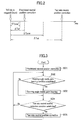
- the EPS_ECU 20 determines as the yaw rate neutral position a value detected by the yaw rate sensor S Y when a predetermined time ⁇ Tyaw, which is shorter than the predetermined time ⁇ Tst, has passed since the vehicle 1 was stopped.
- the yaw rate sensor S Y can be stabilized as described above.
- the EPS_ECU 20 can accurately correct the yaw rate neutral position by determining as the yaw rate neutral position a value of the yaw rate sensor S Y detected when the yaw rate sensor S Y is stabilized.
- a time by which the yaw rate sensor S Y is stabilized may be set as the predetermined time ⁇ Tst in advance based on an experiment.
- the predetermined time ⁇ Tyaw is not limited to a specified unique time and may be set appropriately according to the characteristic of the yaw rate sensor S Y .
- the predetermined time ⁇ Tyaw may also be set to be equal to the predetermined time ⁇ Tst.
- the EPS_ECU 20 when the EPS_ECU 20 is in an unlearned state where the EPS_ECU 20 has not learned the steering angle middle point, such as immediately after the engine of the vehicle 1 is started, conditions for performing the yaw rate neutral position correction are moderated. More specifically, as for the yaw rate neutral position correction performed for the first time after the start of the engine, the predetermined time ⁇ Tst of Fig. 2 , which is the parking time of the vehicle 1, is substantially shortened to be ⁇ Tst'. With this configuration, the EPS_ECU 20 can correct the yaw rate neutral position in a shorter parking time. Further, the EPS_ECU 20 can learn the steering angle middle point based on the detected value of the yaw rate sensor on which the yaw rate neutral position correction is performed.
- the operation angle ⁇ s of the steering wheel 21 is detected as the steering angle sensor S HA , and the EPS_ECU 20 calculates the steering angles ⁇ of the steered wheels 2 FL , 2 FR based on the operation angle ⁇ s, however, an embodiment of the present invention is not limited to this.
- the method of the first embodiment of the present invention for correcting a reference point of a sensor can be applied to a vehicle which is configured such that the movement amount of the rack shaft 4a is detected to allow the EPS_ECU20 to calculate and obtain the steering angle ⁇ .
- the yaw rate sensor S Y in which the neutral position is fluctuated may output a value indicating that the yaw rate ⁇ is not generated even when the driver operates the steering wheel 21 and the vehicle 1 is turning.
- the EPS_ECU 20 may determine that the vehicle 1 runs straight even if the vehicle 1 is turning, whereby the EPS_ECU20 may wrongly learn the steering angle middle point.
- the method of the second embodiment is configured such that when the running vehicle 1 is stopped, the yaw rate neutral position is corrected before the temperature of the engine room 3 is increased by the heat of the engine, and if the temperature of the engine room 3 is increased, the yaw rate neutral position is not corrected.
- the EPS_ECU 20 can prevent the yaw rate sensor S Y from being affected by the temperature increase of the engine room 3 by correcting the yaw rate neutral position immediately after the vehicle 1 is stopped. More specifically, the EPS_ECU 20 can correct the yaw rate neutral position at a sensor temperature close to that of the yaw rate sensor S Y of the running vehicle 1, which allows to reduce the neutral position value fluctuation generated in the yaw rate sensor S Y of the running vehicle 1.
- the EPS_ECU 20 makes it possible to learn the steering angle middle point by using the value detected by the yaw rate sensor S Y on which the yaw rate neutral position correction has been performed, whereby the learning accuracy of the steering angle middle point can be enhanced.
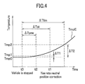
- a time course in which the EPS_ECU 20 corrects the yaw rate neutral position when the vehicle 1 is parked is explained in association with the temperature increase of the engine room 3 indicated by a symbol TmpE.
- Fig. 4 is a graph showing the relationship of the parking time of a vehicle according to the second embodiment and a temperature increase of the engine room.
- the value detected by the yaw rate sensor S Y is fluctuated depending on the variation of the sensor temperature which is affected by the variation of the ambient air temperature, the value detected by the yaw rate sensor S Y is changed when the temperature TmpE of the engine room 3 is changed.
- the temperature difference ⁇ T1 from the running vehicle temperature Tmp0 is small. Therefore, if the yaw rate neutral position is corrected when the temperature TmpE of the engine room 3 is the temperature Tmp1, it is possible to make the neutral position fluctuation generated in the yaw rate sensor SY be smaller in the running vehicle 1.
- the allowable range of the neutral position fluctuation generated in the yaw rate sensor S Y (allowed value) during running of the vehicle 1 is set in advance when the yaw rate neutral position correction is performed in the parking vehicle 1.
- the temperature difference ⁇ T2 can be obtained and set by experiment in advance such that a neutral position fluctuation exceeding the allowed value is generated in the yaw rate sensor S Y of the running vehicle 1 if the yaw rate neutral position is corrected when the temperature difference of the temperature TmpE of the engine room 3 of the parked vehicle 1 and the running vehicle temperature Tmp0 is more than ⁇ T2.
- the time period ⁇ Tlim which is the time period from the time when the running vehicle was stopped to the time when the temperature TmpE of the engine room 3 is increased so that the temperature difference between the temperature TmpE and the running vehicle temperature Tmp0 reaches ⁇ T2 can be measured under various conditions and set. It is preferable that the predetermined time period ⁇ Tst is set to be shorter than the time period ⁇ Tlim which is a time period from the time when the running vehicle stopped to the time when the temperature TmpE of the engine room 3 is increased so that the temperature difference between the temperature TmpE and the running vehicle temperature Tmp0 reaches ⁇ T2.
- the predetermined time ⁇ Tst according to the second embodiment is different from that of the first embodiment in that the predetermined time ⁇ Tst according to the second embodiment is set to be shorter than the time period ⁇ Tlim which is set based on the allowed value of the neutral position fluctuation which is allowed in the yaw rate sensor S Y of the vehicle 1.
- the predetermined time ⁇ Tst according to the second embodiment corresponds to "a second predetermined time” described in Claims. "When the yaw rate neutral position correction condition is met" described in accordance with the second embodiment corresponds to "when a status of the vehicle meets a predetermined condition" described in Claims.
- the EPS_ECU 20 can correct the yaw rate neutral position when the temperature difference between the temperature TmpE of the engine room 3 and the running vehicle temperature Tmp0 is smaller than ⁇ T2 in a case where the running vehicle 1 is stopped.
- the neutral position fluctuation generated in the yaw rate sensor S Y of the running vehicle 1 can be made smaller than the allowed value.
- the allowed value of the neutral position fluctuation generated in the yaw rate sensor S Y of the running vehicle 1 may be set appropriately based on the performance (sensitivity) of the yaw rate sensor S Y or a driving performance required for the vehicle 1, etc.
- the predetermined time ⁇ Tyaw may also be set to be equal to the predetermined time ⁇ Tst).
- the neutral position fluctuation generated in the yaw rate sensor S Y of the running vehicle 1 becomes greater than the allowed value.
- the neutral position fluctuation generated in the yaw rate sensor S Y has a large influence on the learning of the steering angle middle point by the EPS_ECU 20, which deteriorates the learning accuracy of the steering angle middle point by the EPS_ECU 20.
- the second embodiment is configured to solve the above problem, and the characteristic thereof is that in a case where the running vehicle 1 is stopped the EPS_ECU 20 corrects the yaw rate neutral position only once at the time t1 when the vehicle 1 has been stopped for the predetermined time ⁇ Tst since the vehicle 1 was stopped.
- the steering angle middle point learning is a process performed when the vehicle 1 is running.
- the EPS_ECU 20 does not determine that the vehicle 1 runs straight if the vehicle 1 is actually turning.
- the learning accuracy of the steering angle middle point is enhanced.
- the EPS_ECU 20 according to the second embodiment can correct the yaw rate neutral position of the yaw rate sensor S Y only once when the temperature difference between the temperature TmpE of the engine room 3 and the running vehicle temperature Tmp0 is smaller than ⁇ T2.
- the EPS_ECU 20 according to the second embodiment can prevent the yaw rate sensor S Y from being affected by the temperature increase of the engine room 3 when correcting the yaw rate neutral position.
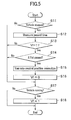
- step S17 the EPS_ECU20 checks whether or not the vehicle 1 is running. If the EPS_ECU 20 determines that the vehicle 1 is running (Yes), the processing proceeds to step S 18 and sets the running determination flag Vf to be "1". If the EPS_ECU20 determines that the vehicle 1 is not running in step S17 (No), the processing is terminated without changing the value of the running determination flag Vf. The processing then returns to step S 11 and repeats the following steps.
- step S 17 the EPS_ECU 20 determines that the vehicle 1 starts to run when the vehicle 1 runs for a predetermined time set in advance at a speed equal to or faster than a predetermined speed set in advance.
- the predetermined speed and the predetermined time may be set to be a speed and a time required for the temperature of the engine room 3 of the vehicle 1 to be decreased to a temperature close to the ambient temperature.
- the EPS_ECU 20 corrects the yaw rate neutral position only once when the predetermined time ⁇ Tst has passed for the first time with the vehicle 1 being parked since the running vehicle was stopped.
- the EPS_ECU 20 can correct the yaw rate neutral position when the temperature difference between the temperature TmpE of the engine room 3 and the running vehicle temperature Tmp0 is small (e.g. smaller than ⁇ T2 shown in Fig. 4 ).
- the EPS_ECU 20 can correct the yaw rate neutral position when the sensor temperature of the yaw rate sensor S Y is close to that when the vehicle 1 is running.
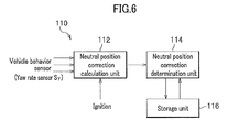
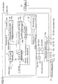
- Fig. 6 is a block diagram showing the reference point correcting device to which the method of the third embodiment is applied.
- Fig. 7 is a flow chart showing the control process for correcting a reference point of a sensor according to the third embodiment.
- step S22 If the neutral position correction value is not obtained (i.e. the neutral position correction condition is not met) in step S22 (No), signals from the yaw rate sensor S Y and other vehicle behavior sensors are repeatedly input to the neutral position correction calculation unit 112. In short, the processing of step S22 is repeatedly performed to determine whether or not the neutral position correction condition is met.
- step S24 the neutral position correction determination unit 114 reads out a previous yaw rate correction value stored in the storage unit 116 and determines whether or not there is the previous yaw rate correction value. At this time, if the previous neutral position correction value is not stored (No), the processing proceeds to step S25 where the present neutral position correction value is stored in the storage unit 116 as the neutral position correction value (stored data), and the processing returns to step S22.
- step S23 the processing of step S23 for obtaining the neutral position correction value is executed at least two times.
- the neutral position correction values can be narrowed down by the reference point correction condition before the reference point correction determining step, which allows the vehicle to appropriately cope with the fluctuation of the detected value of the vehicle behavior sensor in the running vehicle.
- a correction determination time period for comparing the previous neutral position correction value with the present neutral position correction value is set longer than the time period in which the vehicle runs on such a cant road.
- the yaw rate sensor S Y and the temperature sensor S TY is incorporated in the VSA_ECU 30, for example.
- the yaw rate sensor S Y is a sensor which uses a semiconductor element, and its detected value is varied depending on the temperature fluctuation of the yaw rate sensor S Y .
- the VSA_ECU 30 is connected to a braking device B (shown as “B FL , B FR , B FL , B RR " in Fig. 8 ) provided to each wheel 2 FL , 2 FR , 2 RL , 2 RR such that the VSA_ECU 30 is communicated with a hydraulic circuit control unit 31a which drives a control valve (not shown) included in a hydraulic circuit 31 which individually supplies a hydraulic pressure to each braking device B.
- the VSA_ECU 30 controls each braking device B FL , B FR , B FL , B RR via the hydraulic circuit control unit 31a by outputting a control signal to the hydraulic circuit control unit 31a or receiving a hydraulic pressure signal from the hydraulic circuit control unit 31 a.
- the yaw rate sensor S Y and the neutral position learning condition establishment determination unit 42, the neutral position determination unit 43, the learned neutral position storing unit 44, the yaw rate correction unit 45 and the non volatile memory 30f of the VSA_ECU 30 corresponds to "vehicle behavior detection system" described in Claims.
- the neutral position learning condition establishment determination unit 42a does not output a signal which allows the neutral position learning to the neutral position determination unit 43.
- the present vehicle speed Vs, the steering angle ⁇ , the steering torque Trq and the yaw rate ⁇ which is the detected value corresponds to "vehicle behavior information" described in Claims.
- the learned neutral position storing unit 44 stores the yaw rate neutral position value ⁇ 0 which is output from the neutral position determination unit 43 in the neutral position data unit 44a in the non volatile memory 30f.
- the yaw rate correction unit 45 outputs the yaw rate ⁇ * which is obtained by correcting the current yaw rate ⁇ based on the corrected neutral position to the VSA controlling unit 46.
- the yaw rate correction unit 45 outputs the yaw rate ⁇ * on which the neutral position correction has been performed to the EPS_ECU20 via the CAN communication.
- the VSA controlling unit 46 performs the VSA control of the vehicle 1 by controlling the braking devices B of each wheel 2 via the hydraulic circuit 31 based on the vehicle speed Vs, the yaw rate ⁇ * which has been corrected based on the corrected neutral position, the steering angle ⁇ , and the lateral acceleration ⁇ X .
- the VSA controlling unit 46 also performs a braking control via the hydraulic circuit 31 and monitors the wheel speed V W of the wheel 2 to perform the ABS control to prevent the wheels 2 from being locked when the driver steps on the brake pedal PB (see Fig. 8 ).
- step S32 the neutral position determination unit 43 checks whether or not the difference between the outer air temperature T Air and the yaw rate sensor temperature T Y is smaller than a threshold value ⁇ TY . If the difference between the outer air temperature T Air and the yaw rate sensor temperature T Y is smaller than the threshold value ⁇ TY (Yes), the neutral position determination unit 43 outputs the current yaw rate ⁇ , which is the detected value, to the learned neutral position storing unit 44 as the yaw rate neutral position value ⁇ 0 (obtains the reference point), and the processing proceeds to step S33.
- the neutral position of the yaw rate sensor S Y is learned only when the temperature of the vehicle 1 (see Fig. 8 ) is at the yaw rate sensor temperature T Y which is close to the outer air temperature T Air .
- T Y which is close to the outer air temperature T Air .
- the VSA_ECU 30 is described to learn the neutral position of the yaw rate sensor S Y in the fourth embodiment; however, an embodiment of the present invention is not limited to this.
- the VSA_ECU 30 may transmit the yaw rate ⁇ which is the detected value to the EPS_ECU 20 via the CAN communication line 50 and the EPS_ECU 20 may learn the neutral position in the method as described above and may transmit the yaw rate ⁇ * which has been corrected based on the corrected neutral position to other ECU, such as the VSA_ECU 30, via the CAN communication line 50 to use the yaw rate ⁇ * which has been corrected based on the corrected neutral position in the VSA control.
- An embodiment of the present invention may also be configured that the yaw rate ⁇ which is the detected value of the yaw rate sensor S Y is directly input to the EPS_ECU 20, and the EPS_ECU 20 learns the neutral position by the method as described above and transmits the yaw rate ⁇ * which has been corrected based on the corrected neutral position to other ECU, such as the VSA_ECU 30, via the CAN communication line 50 to use the yaw rate ⁇ * which has been corrected based on the corrected neutral position in the VSA control.
- the CPU 30a of the VSA_ECU 30 includes a vehicle speed calculation unit 41, an neutral position learning condition establishment determination unit 42, an neutral position determination unit 43, a learned neutral position storing unit (reference point storage unit, the reference point correction time temperature storage unit) 44, a yaw rate correction unit 45 and a VSA controlling unit 46 as functional configuration units which are realized by executing the programs stored in the ROM 30c.
- the vehicle speed calculation unit 41 reads signals indicating the wheel speed V W from the wheel speed sensor S VW , calculates the vehicle speed Vs of the vehicle 1 and outputs the vehicle speed Vs to the neutral position learning condition establishment determination unit 42 and the VSA controlling unit 46.
- the neutral position learning condition establishment determination unit 42 includes a neutral position learning condition data 42a which is stored in the ROM 30c in advance, and determines whether or not the learning condition of the neutral position of the yaw rate sensor S Y is met based on the current vehicle speed Vs, steering angle ⁇ , steering torque Trq and the yaw rate ⁇ which is the detected value. If the learning condition is met, the neutral position learning condition establishment determination unit 42 outputs a signal allowing the learning of the neutral position to the neutral position determination unit 43. If the learning condition is not met, the neutral position learning condition establishment determination unit 42 does not output a signal allowing the learning of the neutral position to the neutral position determination unit 43.
- the learned neutral position storing unit 44 stores the yaw rate neutral position value ⁇ 0 output from the neutral position determination unit 43 in the neutral position data unit 44a of the non volatile memory (reference point storage unit, reference point correction time temperature storage unit) 30f.
- the learned neutral position storing unit 44 also stores the neutral position learning time temperature T Y * in the neutral position learning time temperature data unit 44b of the non volatile memory 30f.
- the yaw rate correction unit 45 outputs the yaw rate ⁇ * which is obtained by correcting the current yaw rate ⁇ based on the corrected neutral position to the VSA controlling unit 46.
- the yaw rate correction unit 45 outputs the yaw rate ⁇ * which has been corrected based on the corrected neutral position, the neutral position learning time temperature T Y * and the current yaw rate sensor temperature T Y to the EPS_ECU 20 via the CAN communication.
- the VSA controlling unit 46 performs the VSA control of the vehicle 1 by controlling the braking devices B of each wheel 2 via the hydraulic circuit 31 based on the vehicle speed Vs, the yaw rate ⁇ * on which the neutral position correction is performed, the steering angle ⁇ , and the lateral acceleration ⁇ x .
- the VSA controlling unit 46 also performs a braking control via the hydraulic circuit 31 and the ABS control to prevent the wheels 2 from being locked by monitoring the wheel speed V W of the wheel 2 when the driver steps on the brake pedal PB (see Fig. 8 ).
- Fig. 12 is a functional block diagram of the EPS_ECU according to the fifth embodiment.
- Fig. 13 is a graph for explaining a yaw rate reaction force correction restriction factor in the fifth embodiment.
- the EPS_ECU 20 includes a basic control unit 51, a steering reaction force control unit 52, a subtracter 53 and a drive electricity control unit 54.
- a target electricity It corresponding to a steering assistance force to be generated by the motor 23 is calculated in the subtracter 53.
- the basic control unit 51 calculates a base electricity Ib which is the base of the target electricity It corresponding to the steering assistance force generated in the motor 23 based on the manual steering force input from the steering wheel 21 (see Fig. 8 ).
- the basic control unit 51 also performs required correction on the base electricity Ib to obtain an assist electricity Ia.
- the basic control unit 51 includes a base electricity calculation unit 61, an inertia compensation unit 62 for compensating the inertia of the steering system and a damper compensation unit 63 for compensating the damping of the steering system.
- the steering system of the description "inertia of the steering system” and “damping of the steering system” means to include the motor 23 in the steering system in addition to the steering mechanism such as the pinion shaft 11 and the rack shaft.
- the vertical axis in the function data or the map data 66a indicates a yaw rate reaction force correction restriction factor C which is to be multiplied with the yaw rate reaction force correction electricity Iy.
- the yaw rate reaction force correction restriction factor C is 1.0 when the
- the yaw rate reaction force correction restriction factor C is decreased as current temperature T Y - learning time temperature T Y *
- a process performed by the yaw rate reaction force restriction unit 66 to calculate the difference between the neutral position learning time yaw rate sensor temperature T Y * and the current yaw rate sensor temperature T Y and to multiply the yaw rate reaction force correction electricity Iy with the yaw rate reaction force correction restriction factor C determined based on the function data or map data 66a with reference to the difference corresponds to a process "adjusts a correction amount of a control performed according to a detected value of the vehicle behavior sensor based on a difference between the reference point correction time temperature and a current vehicle behavior sensor temperature" recited in Claims.
- the basic control unit 51 sets an assist electricity Ia to increase as a manual steering torque is increased.
- the steering reaction force control unit 52 sets a yaw rate reaction force correction electricity Iy in such a manner that the absolute value of the yaw rate reaction force correction electricity Iy is increased as the absolute value of an actual yaw rate (corrected yaw rate) ⁇ * is increased.
- the steering assistance force of the motor 23 is reduced and a steering reaction force applied to the driver becomes larger.
- the steering wheel 21 is felt to be heavy, which allows the driver to recognize the instability of the vehicle 1 and to suppress the rotation operation of the steering wheel 21 by the driver.
- it is possible to enhance the running stability of the vehicle 1 as well as to enhance the operability of the vehicle 1 for the driver.
- the yaw rate reaction force correction electricity Iy* is subtracted from the assist electricity Ia which is input from the basic control unit 51 and the target electricity It is input to the drive electricity control unit 54.
- the drive electricity control unit 54 controls electricity supplied to the motor 23 from the motor driving circuit 22 in such a manner that a deviation between an actual electricity (indicated as "IU, IV, IW” in Fig. 12 ) in U-phase, V-phase and W-phase which are supplied to the motor 23 from the motor driving circuit 22 and the target electricity It becomes small. More specifically, the drive electricity control unit 54 controls a duty signal which is to be input to a switching element included in the motor driving circuit 22 in such a manner that the deviation becomes small.
- the yaw rate reaction force restriction unit 66 in the EPS_ECU 20 controls a yaw rate reaction force correction electricity Iy which is calculated in the yaw rate reaction force correction electricity calculation unit 65 based on the actual yaw rate ⁇ * which has been corrected on the basis of the neutral position value ⁇ 0 learned at the yaw rate sensor temperature T Y * to be smaller as the difference between the neutral position learning time yaw rate sensor temperature T Y * and the current yaw rate sensor temperature T Y becomes larger.
- the neutral position of the yaw rate sensor S Y is learned in the VSA_ECU 30 (see Fig. 11 ) in the fifth embodiment, however, an embodiment of the present invention is not limited.
- an embodiment of the present invention may be configured that the VSA_ECU 30 transmits the yaw rate ⁇ , which is a detected value, to the EPS_ECU20 via the CAN communication line 50 and the EPS_ECU 20 learns the neutral position in the method as described above and transmits the yaw rate ⁇ * which has been corrected based on the corrected neutral position to other ECU, such as the VSA_ECU 30 via the CAN communication line 50 to use the yaw rate ⁇ * corrected based on the corrected neutral position in a VSA control.
- An embodiment of the present invention may also be configured that the yaw rate ⁇ which is a value detected by the yaw rate sensor S Y is directly input to the EPS_ECU 20 and the EPS_ECU 20 learns the neutral position in the method as described above and transmits the yaw rate ⁇ * corrected based on the corrected neutral position to other ECU, such as the VSA_ECU 30 via the CAN communication line 50 to use the yaw rate ⁇ * corrected based on the corrected neutral position in the VSA control.
- the yaw rate ⁇ which is a value detected by the yaw rate sensor S Y is directly input to the EPS_ECU 20 and the EPS_ECU 20 learns the neutral position in the method as described above and transmits the yaw rate ⁇ * corrected based on the corrected neutral position to other ECU, such as the VSA_ECU 30 via the CAN communication line 50 to use the yaw rate ⁇ * corrected based on the corrected neutral position in the VSA control
- the temperature of the vehicle behavior sensor corresponds to “the yaw rate sensor temperature T Y " in the fifth embodiment, however, "the temperature of the vehicle behavior sensor” recited in Claims may be the temperature of the yaw rate sensor S Y or the environmental temperature of the yaw rate sensor S Y .
- the steering reaction force control unit 52 of the CPU 20a of the EPS_ECU 20 controls the reaction force component of the steering assistance force based on the yaw rate ⁇ *, however, as disclosed in Japanese Unexamined Patent Application Publication No. 2006 - 256425 , the steering reaction force control unit 52 may control the reaction force component of the steering assistance force based on the yaw rate ⁇ * and the steering angle ⁇ .
- the vehicle 1 to which methods for correcting a sensor reference point according to the first to fifth embodiments are applied is not limited to a vehicle including an engine such as gasoline engine or diesel engine as a driving source, but may be a EV vehicle (electric vehicle) which includes a motor as a driving source.
- a sensor reference point correction method which corrects the yaw rate neutral position of a yaw rate sensor when a predetermined time ⁇ Tst has passed with a vehicle being parked since the running vehicle was stopped.
- a provisional neutral position correction of the yaw rate sensor is performed when a predetermined time ⁇ Tst' which is shorter than a predetermined time ⁇ Tst has passed with the vehicle being parked.
Landscapes
- Engineering & Computer Science (AREA)
- Physics & Mathematics (AREA)
- Chemical & Material Sciences (AREA)
- Combustion & Propulsion (AREA)
- Transportation (AREA)
- Mechanical Engineering (AREA)
- General Physics & Mathematics (AREA)
- Mathematical Physics (AREA)
- Steering Control In Accordance With Driving Conditions (AREA)
Abstract
Description
- The present invention relates to a method for correcting a reference point of a sensor provided to a vehicle and an electric power steering device using the method.
- A vehicle has been known which includes an electric power steering (EPS : Electric Power Steering) device for reducing a steering force of a driver. Such a vehicle includes an EPS ECU (Electronic Control Unit) for controlling the electric power steering device. In a vehicle including a VSA (Vehicle Stability Assist) which uses functions of ABS (Anti Lock Brake System) and TCS (Traction Control System) for controlling the behavior of the vehicle by controlling a braking system for wheels of the vehicle, a VSA_ECU for controlling the behavior of the vehicle is provided.
- An EPS_ECU controls an electric power steering device based on a vehicle behavior such as a vehicle travel status (e.g. turning or advancing) and a vehicle speed to generate steering assistance force so that the steering force of a driver is reduced. The EPS_ECU also controls the electric power steering device to perform a reaction force control (a control for generating a reaction force against the operation of the steering wheel) based on an operation angle of a steering wheel (i.e. the steering angles of front wheels, which are steered wheels).
Some of the vehicles including an electric power steering device is provided with a vehicle behavior detection system which has a sensor for detecting a vehicle behavior. Specifically, the vehicle behavior detection system is provided with a yaw rate sensor, a steering angle sensor, a lateral acceleration sensor and a front and rear acceleration sensor, etc. as a vehicle behavior detection sensor for detecting turning of the vehicle. - As the steering angle sensor, a sensor detecting a relative angle change amount of the steering wheel may be used (e.g. rotary encoder). In this case, the EPS_ECU can calculate the operation angle of the steering wheel (i.e. the steering angle of the steered wheels) by using the angle change amount from a reference point, which is the neutral position of the steering wheel (i.e. a steering angle middle point).
Thus, the EPS_ECU needs to learn the steering angle middle point (i.e. needs to correct the reference point of the steering angle). A yaw rate detected by a yaw rate sensor is used to correct the reference point of the steering angle.
Therefore, a yaw rate sensor is required to accurately detect a yaw rate in order to enhance the accuracy of correcting the reference point of the steering angle.
"Learning the steering angle middle point" described here corresponds to "correcting a reference point of a sensor" described in Claims. - There has been known a yaw rate sensor such as those disclosed in
Patent document 1 which includes a semiconductor element. Such a yaw rate sensor has a characteristic that the detected value is largely varied depending on a temperature (sensor temperature). As an ambient air temperature is changed by traveling of the vehicle, the temperature of the yaw rate sensor is also continuously changed. Therefore, in order to accurately detect the yaw rate of the driving vehicle, it is preferable that the neutral position of the yaw rate sensor in a state where the yaw rate is 0 (not in a turning state) is learned appropriately (i.e. the reference point is corrected as appropriate). "Correcting the reference point of the yaw rate sensor in the state where the yaw rate is 0" described here corresponds to "correcting a reference point of a sensor" described in Claims. - For example,
Patent Document 2 discloses a steering angle neutral position learning system in which a provisional neutral position of the steering wheel is set when the ignition switch is turned ON, and the provisional neutral position is corrected in response to the subsequent driving status of the vehicle as appropriate to learn the accurate neutral position (steering angle middle point). - Vehicle behavior sensors are affected by various internal and external disturbances (see Patent Document 3). For example, an environment of the various vehicle behavior sensors or the running status of the vehicle is continuously changed, and the vehicle behavior sensors are subjected to aged deterioration. Therefore, even if vehicle behaviors are the same, different values may be detected from a vehicle behavior sensor. To cope with this problem, a relative value is used for a detected value of the vehicle behavior sensor. Thus, neutral position learning is performed to learn a reference point of each sensor for using signals from each vehicle behavior sensor for various control processes. For example, in detected values such as a "yaw rate", "acceleration" and "steering angle", which need a reference point for determining a relative value, the neutral position learning of "yaw rate", "acceleration" and "steering angle", etc. is performed taking a vehicle speed or a detected time, etc. into consideration as well as the output value of each vehicle behavior sensor.
"The neutral position learning of vehicle behavior sensors" described herein corresponds to "correcting a reference point of a sensor" recited in Claims. - Such neutral position learning has been performed easily and accurately when a vehicle is stopped, however, recently the neutral position learning has also been performed during running of a vehicle to realize more precise and accurate control and to cope with the increase of vehicle behavior control items. Systems and devices which perform vehicle behavior control includes an electric power steering device, an navigation system, a four wheel drive steering system, and vehicle body attitude control device.
- Further,
Patent Document 4 discloses a technique for correcting a reaction force applied to a steering wheel based on a signal from a yaw rate sensor. -
- Patent document 1: Japanese Unexamined Patent Application Publication No.
2000 - 81335 - Patent document 2: Japanese Patent No.
3728991 - Patent document 3: Japanese Unexamined Patent Application Publication No.
04 - 213067 - Patent document 4: Japanese Unexamined Patent Application Publication No.
2008 - 221869 - In the technique disclosed in
Patent Document 2, it is determined whether or not a vehicle is running straight based on the detected value from the yaw rate sensor. However,Patent Document 2 does not disclose learning of the neutral position of the yaw rate sensor, and thus the technique disclosed inPatent Document 2 has a problem that steering angle middle point can not be accurately learned if the detected value of the yaw rate sensor is fluctuated depending on the variation of the sensor temperature (i.e. if the neutral position of the yaw rate sensor is not correct). - In order to solve this problem a configuration is preferable in which the neutral position of the yaw rate sensor is corrected as appropriate.
A yaw rate sensor corrects a neutral position by determining as a neutral position a value detected when a yaw rate is not generated in a vehicle. Thus, it is possible to determine as a reference value a detected value when a vehicle is stopped, for example.
As the yaw rate sensor is not stable immediately after a running vehicle is stopped due to the resonance of vibration caused by driving. Thus, the value detected when the yaw rate sensor becomes stable after a predetermined time has passed since the vehicle was stopped is determined to be a reference value, whereby the neutral position of the yaw rate sensor can be accurately corrected. - In such a configuration, it is preferable that the vehicle has been parked for several seconds since the running vehicle was stopped in order to stabilize the yaw rate sensor. Thus, several seconds needs to be passed after the running vehicle was stopped to correct the neutral position of the yaw rate sensor.
- As the yaw rate sensor is stable when the vehicle is started (when the ignition switch is turned ON), the neutral position of the yaw rate sensor can be accurately corrected immediately after the start of the vehicle.
- However, if it is configured that the neutral position of the yaw rate sensor is corrected when several seconds have passed after the vehicle was started, the driver may start to drive the vehicle before an EPS_ECU corrects the neutral position of the yaw rate sensor. In this case, the vehicle runs without correcting the neutral position of the yaw rate sensor.
If the temperature of the yaw rate sensor when the vehicle is running and the temperature of the yaw rate sensor when the vehicle is stopped are different, a yaw rate sensor which learns its neutral position by determining a value detected when the vehicle is stopped as an neutral position value may not be able to accurately detect the yaw rate generated in the running vehicle because the neutral position value is fluctuated depending on the variation of the temperature of the yaw rate sensor. - As described above, if the vehicle status does not continue in which the neutral position of the yaw rate sensor is corrected accurately, the learning accuracy of the EPS_ECU for learning the steering angle middle point of the steering angle sensor is deteriorated, and thus the EPS_ECU cannot accurately perform the reaction force control. As a result, the driver may feel uncomfortable.
Hereinafter, vehicle behavior sensors such as the steering angle sensor and the yaw rate sensor may just be referred to as "a sensor". - The neutral position learning during running is performed under a basal condition that the vehicle runs straight under a constant speed.
Even under this basal condition, small behavior change is always occurred in the vehicle due to the change of wind or a road condition. Thus, in the neutral position learning of the vehicle behavior sensor during running, an allowable range of fluctuation of the detected value of the vehicle behavior sensor is set. - However, due to this allowable condition, the vehicle running state which should not be determined as a neutral position detection state may be determined as the neutral position detection state because of the combined influence of wind, a road condition and the driving technique of the driver.
In the neutral position learning of the yaw rate sensor, this allowable condition (corresponding to a learning condition described later) is, for example, an allowable condition (learning condition) that the variation of the steering torque and the steering angle during running is within a specified range; a low to intermediate speed range is excluded as vehicle speed restriction; and the yaw rate fluctuation in a specified correction determining time period is small enough. When the vehicle gently curves on a cant road, the steering force may be hardly generated even though the vehicle is actually turning (there is a turning radius). In this case, the vehicle status may meet the allowable condition, and the yaw rate detected at this time may be determined as an appropriate neutral position and is falsely learned. As a result, a control difference may be generated between a right yaw rate and left yaw rate which are the same value in the vehicle behavior control device using the yaw rate sensor. - The present invention is made in view of the above problem, and an object thereof is to provide a sensor reference point correction method which can perform a sensor reference point correction as appropriate without being affected by the variation of the sensor temperature and a vehicle running status and an electric power steering device using the method.
- In order to solve the above problem, a sensor reference point correction method of
Claim 1 includes a step of correcting a reference point of a sensor provided to a vehicle when a status of the vehicle meets a predetermined condition, wherein the predetermined condition includes at least one of a time period from an engine start time, a parking time of the vehicle, the difference between the reference point of the sensor before correction and the reference point of the sensor after correction, a vehicle speed, a sensor temperature and an outer air temperature. - The sensor reference point correction method of
Claim 1 includes the step of correcting the reference point of the sensor provided to the vehicle when the status of the vehicle meets the predetermined condition, wherein the predetermined condition includes at least one of the time period from the engine start time, the parking time of the vehicle, the difference between the reference point of the sensor before correction and the reference point of the sensor after correction, the vehicle speed, the sensor temperature and the outer air temperature. Thus, if any one of the conditions of the time period from the engine start time, the parking time of the vehicle, the difference between the reference point of the sensor before correction and the reference point of the sensor after correction, the vehicle speed, the sensor temperature and the outer air temperature is met, the reference point of the sensor can be corrected, which enables to increase the opportunity of performing the sensor reference point correction. Therefore, the detection accuracy of the sensor when the vehicle is running is enhanced. - In the sensor reference point correction method of
Claim 2, the condition is relaxed at the engine start time of the vehicle to correct the reference point of the sensor. - The sensor reference point correction method of
Claim 2 includes the step of correcting the reference point of the sensor when the status of the vehicle meets the predetermined condition, wherein the condition is relaxed at the engine start time of the vehicle to correct the reference point of the sensor. Thus, at the engine start time of the vehicle for example, the correction of the sensor reference point is performed easier. - In the sensor reference point correction method of
Claim 3, in addition to the configuration of the method ofClaim 2, the condition includes that the vehicle has been stopped for a first predetermined time and relaxing of the condition is to shorten the first predetermined time. - In accordance with the sensor reference point correction method of
Claim 3, the reference point of the sensor can be corrected in a shorter time at the engine start time of the vehicle. - In the sensor reference point correction method of
Claim 4, in addition to the configuration ofClaims - The sensor reference point correction method of
Claim 4 is a sensor reference point correction method including the step of correcting the reference point of the sensor provided to the vehicle when the status of the vehicle meets the predetermined condition, wherein the condition is relaxed at the engine start time of the vehicle to correct the neutral position of the yaw rate sensor. Thus, at the engine start time of the vehicle for example, it is made to be easier to correct the sensor reference point. - The sensor reference point correction method of
Claim 5 includes, in addition to the configuration ofClaim 1, a step of correcting the reference point of the sensor at the time when a second predetermined time has passed with the vehicle being stopped since the vehicle was stopped, wherein the reference point of the sensor is not corrected after the second predetermined time has passed with the vehicle being stopped. - In accordance with the method of
Claim 5, the reference point of the sensor can be corrected at the time when a second predetermined time has passed with the vehicle being stopped since the vehicle was stopped, the reference point of the sensor is configured not to be corrected after the second predetermined time has passed with the vehicle being stopped.
Thus, it is possible to prevent the reference point from being corrected in an environment where the temperature is high after the second predetermined time has passed with the vehicle being parked even if the sensor is arranged in the environment where the temperature is increased as time passes from the time when the running vehicle was stopped. - The sensor reference point correction method of Claim 6 includes, in addition to the configuration of the invention of
Claim 1, steps of calculating reference point correction values sequentially from values output by the sensor; and correcting the reference point when substantially the same values of the reference point correction values are calculated continuously, wherein the reference point is not corrected when a previous reference point correction value and a current reference point correction value are different. - In accordance with the invention of Claim 6, the reference point correction value is firstly calculated more than once by the step of calculating the reference point correction values. Here, in a case where the status of the vehicle is in a reference point detection status, even though each of the reference point correction values detected more than once may be varied due to, for example, a secular change, a previous reference point correction value and a current reference point correction value should be substantially same value because the two reference point correction values are detected close in time. In contrast, if the previous reference point correction value and the current reference point correction value are not substantially the same but are different, it can be assumed that the current reference point correction value is going to be falsely learned.
- Such a false learning is likely to be occurred when the vehicle gently curves on a cant road. However, the probability that the vehicle runs on the cant road at both of the times when the previous reference point correction value was calculated and the current reference point correction value is calculated is extremely low because it is rare that the vehicle runs on a cant road with a gentle curve. In other words, if the false learning should be occurred, the false learning would be occurred just once and is hardly continued. Thus, by comparing the previous reference point correction value and the current reference point correction value and performing the correction step recited in Claim 6, it is possible to determine that the neutral point is going to be falsely learned with the current reference point correction value, which enables to prevent the false learning from being occurred.
- In short, in the step of correcting the reference point correction, if the reference point correction values calculated at the step of calculating the reference point correction values are continued to be substantially equal, it is determined that the running status of the vehicle is a status in which the reference point is maintained, and thus the reference point correction value which is substantially the same as the reference point is accepted. On the other hand, if the previous reference point correction value and the current reference point correction value are different, the vehicle behavior when the previous reference point correction value was calculated and the vehicle behavior when the current reference point correction value is calculated are changed, and thus the reference point is not corrected. Therefore, even if a running status of the vehicle which should not be regarded as a reference point detection status is recognized as the reference point detection status and the reference point is likely to be learned, the reference point is not corrected actually in the step of correcting the reference point unless the reference point correction values calculated in the step of calculating the reference point correction value are continued to be substantially the same. Thus, it is possible to avoid the false learning of the reference point, whereby the difference between the right and left operation of the steering handle in the steering reaction force control is prevented from being generated.
- In the sensor reference point correction method of
Claim 7, in addition to the configuration of Claim 6, the reference point correction value is calculated only if the output value of the sensor meets a reference point correction condition, and a new reference point correction value is calculated if the output value of the sensor did not meet the reference point correction condition before but the output value of the sensor is changed to meet the reference point correction condition in the step of calculating the reference point correction values. - In accordance with the invention of
Claim 7, the reference point correction value is calculated only when the output value of the sensor meets the reference point correction condition in the step of calculating the reference point correction value. The reference point correction condition can be set for the running vehicle and a plurality of detection items can be set for the condition for each reference point correction of a sensor which detects a vehicle behavior. Only when the reference point correction condition is met, the reference point correction value is calculated. A new reference point correction value is calculated if the reference point correction condition becomes to be met again by feedback control after the reference point correction condition was not met. - If a range of each detection items are set to be too narrow, a small vehicle behavior change is always detected, which prevents the establishment of the reference point correction condition. On the other hand, if each range of the detection items are too wide, a neutral position learning may be falsely performed when the vehicle is not running straight with a constant speed. The reference point correction condition is appropriately provided taking the problem described above into consideration.
- Since the correction of the reference point is restricted by the reference point correction condition before correcting the reference point as described above, it is possible to more accurately cope with a fluctuation of the detected value of the sensor when the vehicle is running. By feed backing the step of calculating the reference point correction value after the reference point correction condition was not met, a new reference point correction control is performed, and a new reference point correction value is calculated when the reference point correction condition is met again.
- In accordance with the invention of
Claim 7, in a case where the sensor is a yaw rate sensor, the reference point correction value of the yaw rate sensor is calculated in the step of calculating the reference point correction value. In this step of calculating the reference point correction value, only if the output value of the yaw rate sensor and output values of other items meet the reference point correction condition, the reference point correction value may be calculated. This reference point correction condition is, for example, that the variation of the steering torque and the steering angle during running is within a specified range; a low to intermediate speed range is excluded as vehicle speed restriction (because the fluctuation of the yaw rate is too large in the slow to intermediate speed range); and the yaw rate fluctuation in a specified correction determining time period is small enough. In addition to the condition described above, conditions of the lateral acceleration or a longitudinal acceleration may be included. - If substantially equal reference point correction values of the yaw rate are continued, it is determined that the substantially equal reference point correction values of the yaw rate are continued in the step of correcting the reference point when the vehicle is running straight in a constant speed, as described in the invention of Claim 6, whereby the reference point correction value is accepted. On the other hand, if the previous reference point correction value and the current reference point correction value are different, it is determined that the vehicle behavior is changed between the time when the previous reference point correction value was calculated and the time when the current reference point correction value is calculated and the current reference point correction value is falsely calculated. Thus, the reference point is not corrected.
- Even in a case where a vehicle gently curves on a cant road and the steering force is hardly generated even though the vehicle is actually turning (there is a turning radius), the turning radius or the inclination of the cant road are different depending on the detection timing. Thus, in the correction of the yaw rate reference point, the previous reference point correction value and the current reference point correction value become different. Accordingly, the reference point is not corrected, which prevents the false learning of the reference point. This also prevents the generation of the difference in the steering reaction force control between a right control and a left control.
- The sensor reference point correction method of the invention of Claim 8, in addition to the configuration of the invention of
Claim 1, includes a step of obtaining a signal from the sensor as the reference point of the sensor when vehicle behavior information of the vehicle including at least the vehicle speed meets a reference point correction condition of the sensor which is set in advance and the difference between a temperature of the sensor and an outer air temperature is smaller than a predetermined threshold value, while the signal from the sensor is not obtained when the difference between the temperature of the sensor and the outer air temperature is greater than the predetermined threshold value. - In accordance with the invention of Claim 8, if the reference point correction condition is met and the difference between the temperature of the sensor which is arranged in the engine room and the outer air temperature is below the predetermined threshold value, a signal from the sensor is obtained and stored as the reference point, while if the difference is equal to or more than the predetermined threshold value, the signal from the sensor is not obtained as the reference point.
Therefore, only when the sensor temperature when the reference point correction condition is met is close to the temperature of the engine room when the vehicle was running (i.e. the outer air temperature), the reference point is corrected. Thus, even in a case where the temperature of the engine room is increased as time passes since the running vehicle was stopped, it is possible to prevent the reference point from being corrected in an environment where the temperature becomes high with the vehicle being parked. - The sensor reference point correction method of the invention of Claim 9 includes the configuration of the invention of
Claim 1 and is a method which is applied to a vehicle behavior detection system including a reference point storage unit which stores a signal from the sensor as the reference point and a correction unit which corrects the signal from the sensor with the stored reference point and outputs the corrected signal to a vehicle behavior control device which controls a vehicle behavior. The method includes steps of determining whether or not the vehicle behavior information including at least a vehicle speed meets a sensor reference point correction condition which is set in advance; detecting a temperature of the sensor; and detecting an outer air temperature; wherein in a case where the sensor reference point correction condition is determined to be met in the step of determining whether or not the vehicle behavior information including at least the vehicle speed meets the sensor reference point correction condition, if a difference between the detected temperature of the sensor and the detected outer air temperature is below a threshold value, the signal from the sensor is obtained as the reference point and is stored in the reference point storage unit, and if the difference between the detected temperature of the sensor and the detected outer air temperature is equal to or more than the threshold value, the signal from the sensor is not obtained as the reference point. - In accordance with the invention of Claim 9, in a case where the reference point correction condition establishment determination unit determines that the reference point correction condition is met, if the difference between the detected sensor temperature and the detected outer air temperature is below the predetermined threshold value, the signal from the sensor is obtained and stored in the reference point storage unit as the reference point. If the difference between the detected sensor temperature and the detected outer air temperature is equal to or more than the threshold value, the signal from the sensor is not obtained as the reference point.
Thus, if the sensor is arranged in an engine room for example, the reference point is corrected only when the sensor temperature at the time when the reference point correction condition is met is close to the temperature of the engine room when the vehicle was running (i.e. the outer air temperature). Therefore, even in a case where the temperature of the engine room is increased as time passes since the running vehicle was stopped, it is possible to prevent the reference point from being corrected in an environment where the temperature becomes high with the vehicle being parked. - An electric power steering device of Claim 10 includes a motor for applying a power to a steering system which gives a steering angle to a steered wheel; a steering force detection unit for detecting a manual steering force applied to the steering system; a vehicle behavior sensor which detects the vehicle behavior; a control unit which controls the motor to generate a steering assistance force based on at least an output of the steering force detection unit, the control unit correcting a control of a steering reaction force component of the steering assistance force based on a value detected by the vehicle behavior sensor, a vehicle behavior sensor temperature detection unit which detects a temperature of the vehicle behavior sensor; a reference point storage unit which obtains and stores a signal from the vehicle behavior sensor as a reference point; a reference point correction time temperature storage unit which obtains a temperature of the vehicle behavior sensor when the signal from the vehicle behavior sensor is obtained as the reference point and stores the temperature of the vehicle behavior sensor as a reference point correction time temperature; wherein the control unit adjusts a correction amount of a control performed according to a detected value of the vehicle behavior sensor based on a difference between the reference point correction time temperature and a current vehicle behavior sensor temperature.
- In accordance with the invention of Claim 10, the control unit adjusts the correction amount of the control performed according to the detected value of the vehicle behavior sensor based on the difference between the reference point correction time temperature and the current vehicle behavior sensor temperature. Conventionally, if the values detected by the yaw rate sensor is fluctuated depending on the temperature variation of the yaw rate sensor (i.e. in a case where the reference point of the yaw rate sensor is not correct) a yaw rate which has been corrected based on a false yaw rate reference point is used to perform the correction control of a reaction force against the rotation operation of the steering handle (yaw rate reaction force control), whereby different reaction force control is performed for the right yaw rate and left yaw rate which are the same value. This may cause the driver to feel uncomfortable.
However, in accordance with the feature of adjusting the correction amount of the correction control of the reaction force against the rotation operation of the steering handle as described in the invention of Claim 10, it is possible to make the correction amount to be small thereby to reduce the degree of the difference in the reaction force controls for the right yaw rate and the left yaw rate which are the same value when the difference between the reference point correction time vehicle behavior sensor temperature and the current vehicle behavior sensor temperature is large and thus the yaw rate which has been corrected based on the reference point is less accurate. This feature prevents the driver from feeling uncomfortable. - In the electric power steering device described in
Claim 11, in addition to the configuration of Claim 10, the correction amount of the control performed according to the detected value of the vehicle behavior sensor is made to be smaller as the difference between the reference point correction time temperature and the current vehicle behavior sensor temperature becomes larger. - In accordance with the invention of
Claim 11, when the difference between the reference point correction time temperature and the current vehicle behavior sensor temperature is large and a yaw rate which has been corrected based on the reference point is less accurate, it is possible to make the correction amount to be small thereby to reduce the degree of the difference in the reaction force controls for the right yaw rate and left yaw rate which are the same value. This prevents the driver from feeling uncomfortable. - In accordance with the present invention, it is possible to provide a sensor reference point correction method which can perform a sensor reference point correction as appropriate without being affected by the variation of the sensor temperature and a vehicle running status and an electric power steering device using the method.
-
-
Fig. 1 is an electric power steering device of a vehicle to which a method for correcting a reference point of a sensor according to a first embodiment is applied. -
Fig. 2 is an illustration for explaining a time relationship of a parking time of a vehicle and the yaw rate neutral position correction according to the first embodiment. -
Fig. 3 is a flow chart showing the control process of the yaw rate neutral position correction and the steering angle middle point correction. -
Fig. 4 is a graph showing the relationship of the parking time of a vehicle according to a second embodiment of the present invention and a temperature increase of the engine room. -
Fig. 5 is a flow chart showing a process performed by the EPS_ECU of the second embodiment to correct the yaw rate neutral position. -
Fig. 6 is a block diagram showing a sensor reference point correction method according to a third embodiment of the present invention and a reference point correcting device to which the method of the third embodiment is applied. -
Fig. 7 is a flow chart showing the control process for correcting a reference point of a sensor according to the third embodiment. -
Fig. 8 is a block diagram showing a core part of the vehicle including the VSA_ECU according to a fourth embodiment. -
Fig. 9 is a functional block diagram of the VSA_ECU according to the fourth embodiment. -
Fig. 10 is a flow chart showing the control process according to the fourth embodiment for learning the yaw rate neutral position. -
Fig. 11 is a functional block diagram of the VSA_ECU according to the fifth embodiment. -
Fig. 12 is a functional block diagram of the EPS_ECU according to a fifth embodiment of the present invention. -
Fig. 13 is a graph for explaining a yaw rate reaction force correction restriction factor in the fifth embodiment. - A method for correcting a reference point of a sensor according to the first embodiment of the present invention is described with reference to
Figs. 1 to 3 .Fig. 1 is an electric power steering device of a vehicle to which the method for correcting a reference point of a sensor according to the first embodiment is applied.
As shown inFig. 1 , the steering mechanism of avehicle 1 is configured such that asteering wheel 21 is attached via asteering shaft 12 to apinion shaft 11 integrally revolving with a pinion gear (not shown) which is meshed with a rack of arack shaft 4a of a rack andpinion mechanism 4.
When a driver operates thesteering wheel 21, the pinion gear (not shown) is integrally revolved with thepinion shaft 11, moving therack shaft 4a right or left, whereby the right and leftwheels rack shaft 4a, are steered. - The
vehicle 1 includes an electricpower steering device 5. The electricpower steering device 5 includes amotor 23 which generates as a motorized force a steering assistance force (steering assistance torque) for reducing the steering force required when the driver steers thesteering wheel 21 and applies the steering assistance force to a steering mechanism.
A warm (not shown) connected to the output shaft of themotor 23 is meshed with a warm wheel gear (not shown) which is fixed to thepinion shaft 11, and generates a steering assistance torque for rotating thepinion shaft 11 by the revolution of the output shaft of themotor 3 when the driver operates thesteering wheel 21. Thus, the steering force of the driver is reduced. - The electric
power steering device 5 includes anEPS_ECU 20 which controls the electricpower steering device 5 by driving and controlling themotor 23.
TheEPS_ECU 20 is comprised of a micro computer including a CPU(Central Processing Unit), a ROM (Read Only Memory), a RAM (Random Access Memory), etc. and a peripheral circuit. TheEPS_ECU 20 drives and controls programs stored in the ROM by the CPU and drives and controls themotor 23 via themotor driving circuit 22. - The
VSA_ECU 30 for controlling the behavior (vehicle behavior) of thevehicle 1 is comprised of a micro computer including a CPU, a ROM, a RAM (not shown) and a peripheral circuit, etc. The CPU executes programs stored in the ROM, for example, to control the behavior of thevehicle 1 via a braking system (not shown) which is provided to each wheel. TheVSA_ECU 30 is provided, for example, in anengine room 3.
The EPS_ECU20 and theVSA_ECU 30 are connected to each other with a communication line 50 (hereinafter also referred to as "CANcommunication line 50") of a CAN (Controller Area Network) network (hereinafter also referred to as "a CAN network") and are configured such that the EPS_ECU20 and theVSA_ECU 30 can transmit data with each other. - A torque sensor STrq is attached to the
pinion shaft 11, and detects and outputs a signal indicating a steering torque Trq when the driver operates thesteering wheel 21. The detected signal indicating the steering torque Trq is input to theEPS_ECU 20, and thus the EPS_ECU20 obtains the steering torque Trq of thepinion shaft 11. - A yaw rate sensor SY which is a sensor for detecting the behavior of the vehicle is incorporated, for example, into the
VSA_ECU 30 and detects a yaw rate of thevehicle 1 and outputs a signal indicating the yaw rate to theVSA_ECU 30.
The signal indicating the yaw rate γ is input from theVSA_ECU 30 to theEPS_ECU 20 via theCAN communication line 50, and thus theEPS_ECU 20 obtains the yaw rate γ of thevehicle 1. - A vehicle speed sensor SV is connected to the
EPS_ECU 20.
The vehicle speed sensor SV calculates the vehicle speed Vs based on the number of pulses per a unit time which is output from a wheel speed sensor (not shown) provided to each wheel and outputs a signal indicating the vehicle speed Vs. The signal indicating the vehicle speed Vs is input to theEPS_ECU 20, and thus theEPS_ECU 20 obtains the vehicle speed Vs of thevehicle 1.
The CPU of either one of theEPS_ECU 20 or theVSA_ECU 30 may receive a pulse signal from each wheel speed sensor to calculate the vehicle speed Vs based on the wheel speed and outputs the vehicle speed Vs to the other one of theEPS_ECU 20 or theVSA_ECU 30 via theCAN communication line 50. - Furthermore, the
vehicle 1 includes a steering angle sensor SHA for detecting the operation angle of thesteering wheel 21.
The steering angle sensor SHA is comprised of a sensor for detecting the angle change amount of thesteering wheel 21 when the driver operates thesteering wheel 21 and outputs a signal indicating an operation angle θs of thesteering wheel 21. The signal indicating the operation angle θs is input to theEPS_ECU 20 and theEPS_ECU 20 calculates the steering angles δ of the steeredwheels - The
EPS_ECU 20 sets a steering assistance torque which is output by themotor 23 based on the vehicle speed Vs, the steering torque Trq, etc. and outputs a current control signal to themotor driving circuit 22 so that theEPS_ECU 20 outputs the set steering assistance torque. Themotor driving circuit 22 then supplies a driving current Ic to themotor 23 in accordance with the current control signal. The output shaft of themotor 23 is rotated by the supplied driving current Ic, whereby the steering assistance torque is applied to thepinion shaft 11. Thus, the steering force of the driver can be reduced.
TheEPS_ECU 20 executes a reaction force control in which steering reaction force is applied to thesteering wheel 21 based on the vehicle speed Vs, the steering torque Trq, the steering angle δ and the yaw rate γ, etc. - In the first embodiment, the
EPS_ECU 20 is configured to detect the behavior of thevehicle 1 based on detected values of the vehicle speed sensor SV, the steering angle sensor SHA and the yaw rate sensor SY. The vehiclebehavior detection system 7 is comprised of the vehicle speed sensor SV, the steering angle sensor SHA, the yaw rate sensor SY and theEPS_ECU 20. - In a case where the steering angle sensor SHA is a sensor for detecting the angle change amount of the
steering wheel 21, theEPS_ECU 20 learns that thesteering wheel 21 is at a neutral position in which the vehicle runs straight (operation angle neutral position which is a reference point), and calculates the operation angle θs of thesteering wheel 21 based on the steering angle change amount from the operation angle neutral position. In other words, theEPS_ECU 20 learns that the steering angle δ is also the steering angle middle point, which is a reference point when the operation angle θs is the neutral position, and calculates the steering angle steering angle δ based on the steering angle change amount from the steering angle middle point. Thus, the EPS_ECU20 needs to learn the steering angle middle point. The learning of the steering angle middle point by theEPS_ECU 20 is referred to as "the steering angle middle point learning" hereinafter. - It is preferable that the
EPS_ECU 20 regularly learns the steering angle middle point in order to accurately detect the steering angle δ which corresponds to the operation angle θs of thesteering wheel 21. - When the operation angle θs of the
steering wheel 21 is at the neutral position (i.e. the steering angle δ is at the neutral position), thevehicle 1 runs straight. Therefore, theEPS_ECU 20 determines, as the steering angle neutral position, a steering angle δ which is calculated based on the operation angle signal θs input from the steering angle sensor SHA when the yaw rate is not generated in the drivingvehicle 1 in the steering angle middle point learning. - For example, the
EPS_ECU 20 learns that the operation angle θs of thesteering wheel 21 is at the neutral position (i.e. the steering angle middle point) when the following conditions A are met. -
- 1. The vehicle speed Vs of the
vehicle 1 is equal to or more than apredetermined value VEL 1. - 2. The yaw rate γ of the
vehicle 1 is equal to or less than a predetermined threshold value YAW1. - 3. The steering torque Trq of the
pinion shaft 11 is within a predetermined absolute value TRQ1. - 4. The absolute value of the variation of the steering angleδ is equal to or less than ΔDEG1.
- 5. The status described in 1 to 4 continues over a time TIM1.
- As described above, the
EPS_ECU 20 of thevehicle 1 includes a function for learning the steering angle middle point based on the detected value of the steering angle sensor SHA when the yaw rate γ detected by the yaw rate sensor SY is equal to or less than a predetermined value YAW1.
As the yaw rate γ detected by the yaw rate sensor SY is used for the learning of the steering angle middle point by theEPS_ECU 20, it is preferable that a reference point of the yaw rate sensor SY is corrected as necessary in order to enhance the accuracy of detection of the yaw rate by the yaw rate sensor SY. With this configuration, it is possible to enhance the learning accuracy of the steering angle middle point by theEPS_ECU 20.
Hereinafter, the neutral position of the yaw rate sensor SY which is the reference point of the yaw rate sensor SY may be referred to as a yaw rate neutral position. The yaw rate neutral position corresponds to a value detected by the yaw rate sensor SY when a yaw rate is not generated in thevehicle 1.
Correcting the yaw rate neutral position may also be referred to as "neutral position correction (reference point correction) hereinafter. - For example, the
EPS_ECU 20 corrects the yaw rate neutral position by determining as the yaw rate neutral position a value detected by the yaw rate sensor SY when the following condition B is met. - If a predetermined time ΔTyaw which is shorter than a predetermined time ΔTst has passed since the
vehicle 1 was stopped in a case where thevehicle 1 is stopped for a predetermined time ΔTst. - In a case where the vehicle is running, the
EPS_ECU 20 corrects the yaw rate neutral position by determining as the yaw rate neutral position a value detected by the yaw rate sensor SY when the following conditions C are met. -
- 1. The variation range of the yaw rate γ is within a predetermined absolute value ΔYAW2.
- 2. The absolute value of the steering torque Trq of the
pinion shaft 11 is within a predetermined value TRQ2. - 3. The absolute value of the variation range of the steering angle δ is within a predetermined value ΔDEG2.
- 4. The vehicle speed Vs is equal to or more than a predetermined value VEL2.
- 5. The status described in 1 to 4 continues over a time TIM1.
- Predetermined values (VEL1, YAW1, TRQ1 , ΔDES1, TIM1, ΔYAW2, TRQ2, ΔDEG2, VEL2, TIM2) of the conditions A and C may be set appropriately depending on the performance required for the
vehicle 1 and the sensitivity of the steering angle sensor SHA and the yaw rate sensor SY.
A detailed method of setting a predetermined time ΔTst, ΔTyaw are described later. - The
EPS_ECU 20 corrects the neutral position of the yaw rate when either one set of the condition B and the conditions C is met, and when the set of conditions A is met theEPS_ECU 20 learns the steering angle middle point based on the detected value of the yaw rate sensor SY on which neutral position correction has been performed. By appropriately leaning the steering angle middle point as described above, theEPS_ECU 20 can accurately calculate the steering angle δ based on the operation angle θs of thesteering wheel 21. TheEPS_ECU 20 can preferably perform the reaction force control based on the accurate steering angle δ which corresponds to the operation angle θs of thesteering wheel 21. - Next, the yaw rate neutral position correction is described with reference to
Fig. 2. Fig. 2 is an illustration for explaining a time relationship of a parking time of a vehicle and the yaw rate neutral position correction according to the first embodiment.
In a case where theEPS_ECU 20 performs the yaw rate neutral position correction when the runningvehicle 1 is stopped, thevehicle 1 needs to be stopped for a predetermined time ΔTst as shown inFig. 2 .
After a predetermined time ΔTst has passed since the vehicle was stopped, theEPS_ECU 20 determines as the yaw rate neutral position a value detected by the yaw rate sensor SY when a predetermined time ΔTyaw, which is shorter than the predetermined time ΔTst, has passed since thevehicle 1 was stopped.
When the runningvehicle 1 is parked for the predetermined time ΔTst since thevehicle 1 was stopped, the yaw rate sensor SY can be stabilized as described above. Thus, theEPS_ECU 20 can accurately correct the yaw rate neutral position by determining as the yaw rate neutral position a value of the yaw rate sensor SY detected when the yaw rate sensor SY is stabilized. - Therefore, a time by which the yaw rate sensor SY is stabilized may be set as the predetermined time ΔTst in advance based on an experiment.
The predetermined time ΔTyaw is not limited to a specified unique time and may be set appropriately according to the characteristic of the yaw rate sensor SY. For example, the predetermined time ΔTyaw may be set to be half a time of the predetermined time ΔTst (ΔTyaw = (ΔTst)/2).
The predetermined time ΔTyaw may also be set to be equal to the predetermined time ΔTst. - As described above, the predetermined time ΔTst which is the parking time of the vehicle required for the
EPS_ECU 20 to perform the yaw rate neutral position correction is a time needed for the yaw rate sensor SY to be stabilized, and may set to be several tens of seconds. Thus, if it is configured that the yaw rate neutral position is corrected when the predetermined time ΔTst shown inFig. 2 is passed after the engine of thevehicle 1 is started upon turning on an ignition switch (not shown), the driver may start and drive thevehicle 1 before the predetermined time ΔTst is passed.
If thevehicle 1 starts to run before the predetermined time ΔTst is passed after the start of the engine, thevehicle 1 runs without the yaw rate neutral position being corrected by theEPS_ECU 20. - After that, the
EPS_ECU 20 can not correct the yaw rate neutral position until the status of thevehicle 1 meets either one set of the conditions B and C, and thus can not learn the steering angle middle point.
Thus, theEPS_ECU 20 cannot accurately correct and calculate the steering angle δ corresponding to the operation angle θs of thesteering wheel 21 and cannot preferably perform the reaction force control on thesteering wheel 21. This may cause the driver to feel uncomfortable when operating thesteering wheel 21. - To solve the above problem in the first embodiment, when the
EPS_ECU 20 is in an unlearned state where theEPS_ECU 20 has not learned the steering angle middle point, such as immediately after the engine of thevehicle 1 is started, conditions for performing the yaw rate neutral position correction are moderated.
More specifically, as for the yaw rate neutral position correction performed for the first time after the start of the engine, the predetermined time ΔTst ofFig. 2 , which is the parking time of thevehicle 1, is substantially shortened to be ΔTst'.
With this configuration, theEPS_ECU 20 can correct the yaw rate neutral position in a shorter parking time. Further, theEPS_ECU 20 can learn the steering angle middle point based on the detected value of the yaw rate sensor on which the yaw rate neutral position correction is performed. - For example, when the
vehicle 1 whose engine is just started is parked for the parking time ΔTst' which is shorter than the parking time ΔTst, theEPS_ECU 20 provisionally performs the neutral position correction on the yaw rate sensor SY by determining as the yaw rate neutral position (provisional neutral position) of the yaw rate sensor SY a value detected by the yaw rate sensor SY when the predetermined time ΔTyaw' which is shorter than the parking time ΔTst' is passed. The provisional correction of the neutral position of the yaw rate sensor SY may be referred to as a provisional neutral position correction.
In short, theEPS_ECU 20 performs the provisional neutral position correction on the yaw rate sensor SY after the engine of thevehicle 1 is started. - For example, if the
vehicle 1 can start to run in an approximately 10 seconds from the time when the driver turns on the ignition switch (not shown) and starts the engine of thevehicle 1, the parking time ΔTst' which is shorter than 10 seconds (for example, 5 seconds) is set in advance, and the predetermined time ΔTyaw' is set to be shorter than the parking time ΔTst'. In short, theEPS_ECU 20 moderates the conditions for learning the yaw rate neutral position to perform the provisional neutral position correction. - With this configuration, the
EPS_ECU 20 can always perform the provisional neutral position correction on the yaw rate sensor SY after the start of the engine of thevehicle 1.
When the conditions A are met, the EPS_ECU20 can then learn the steering angle middle point based on a detected value of the yaw rate sensor SY on which the provisional neutral position correction has been performed. - With reference to
Figs. 1 to 3 , a process performed by the EPS_ECU20 for correcting the yaw rate neutral position and learning the steering angle middle point is described.Fig. 3 is a flow chart showing the control process of the yaw rate neutral position correction and the steering angle middle point correction.
Although omitted in the flow chart shown inFig. 3 , a detected signal from the yaw rate sensor SY provided to theVSA_ECU 30 is input to the EPS_ECU20 via theVSA_ECU 30 and theCAN communication line 50 in a predetermined period. When an elapsed time measured by theEPS_ECU 20 from the start of the engine of thevehicle 1 reaches the predetermined time ΔTyaw', theEPS_ECU 20 temporarily stores the signal detected by the yaw rate sensor SY at this time. When the elapsed time measured from the time when thevehicle 1 was stopped reaches the predetermined time ΔTyaw, theEPS_ECU 20 temporarily stores the signal detected by the yaw rate sensor SY at this time. - If the engine of the
vehicle 1 is started, the EPS_ECU20 performs the provisional neutral position correction on the yaw rate sensor SY in step S01 as shown inFig. 3 . More specifically, the EPS_ECU20 performs the provisional neutral position correction on the yaw rate sensor SY by using the signal detected by the yaw rate sensor SY when the predetermined time ΔTyaw' is reached. - In step S02, the EPS_ECU20 checks whether or not the conditions for learning the steering angle middle point are met after the provisional neutral position correction is performed on the yaw rate sensor SY. The processing of the EPS_ECU20 proceeds to step S03 if the conditions for learning the steering angle middle point are met (Yes) after the provisional neutral position correction is performed on the yaw rate sensor SY. If the conditions for learning the steering angle middle point are not met (No), the processing of the EPS_ECU20 proceeds to step S04. In step S03, the EPS_ECU20 learns the steering angle middle point based on a detected value of the yaw rate sensor SY on which the provisional neutral position correction is performed.
In step S02, the EPS_ECU20 determines that the condition for learning the steering angle middle point is met if the conditions A are met. In contrast, the EPS_ECU20 determines that the condition for learning the steering angle middle point is not met if the conditions A are not met. - Subsequently, the EPS_ECU20 checks whether or not the yaw rate neutral position correction conditions are met in step S04. If the yaw rate neutral position correction condition is met (Yes), the processing proceeds to step S05. If the yaw rate neutral position correction condition is not met (No), the processing returns to step S02 without correcting the yaw rate neutral position.
In step S05, theEPS_ECU 20 corrects the yaw rate neutral position.
When the either one set of the condition B and the conditions C is met, theEPS_ECU 20 determines that the yaw rate neutral position correction condition is met. In contrast, when neither one set of the conditions B nor C is met, theEPS_ECU 20 determines that the yaw rate neutral position correction condition is not met. More specifically, when the condition for correcting the yaw rate neutral position correction is met, theEPS_ECU 20 performs the neutral position correction on the yaw rate sensor SY by using a signal detected by the yaw rate sensor SY when the predetermined time ΔTyaw is passed from the time the vehicle was stopped.
The meaning of "when the yaw rate neutral position correction condition is met" corresponds to "when a status of the vehicle meets a predetermined condition" described in Claims.
The predetermined time ΔTst included in the condition B corresponds to "first predetermined time" described in Claims. - If the
EPS_ECU 20 determines Yes in step S04 where the yaw rate neutral position correction condition is met during a period in which the processing returns to step S02 and theEPS_ECU 20 determines No in step S02 where the steering angle middle point learning conditions are not met, the processing proceeds to step S05 in which theEPS_ECU 20 can correct the yaw rate neutral position. Therefore, theEPS_ECU 20 can learn the steering angle middle point as appropriate in a timing at which the steering angle middle point learning condition is met based NOT on the detected value of the yaw rate sensor SY on which the provisional neutral position correction has been performed but on the detected value of the yaw rate sensor SY on which the yaw rate neutral position correction has been performed. - As described above, the EPS-ECU 20 (see
Fig. 1 ) according to the first embodiment can perform the provisional neutral position correction on the yaw rate sensor SY (seeFig. 1 ) without fail when the engine of the vehicle 1 (seeFig. 1 ) is started. Furthermore, the EPS_ECU20 can learn the steering angle middle point based on the detected value of the yaw rate sensor SY on which the provisional neutral position correction has been performed. - As described above, immediately after the driver starts the engine of the vehicle 1 (see
Fig. 1 ), the EPS_ECU20 (seeFig. 1 ) according to the embodiment shortens the parking time ΔTst required for thevehicle 1 to perform the yaw rate neutral position correction to be ΔTst' and performs the provisional neutral position correction as shown inFig. 2 . In other words, theEPS_ECU 20 moderates the yaw rate neutral position correction condition to perform the neutral position correction (provisional neutral position correction). - With this configuration, even when the
vehicle 1 starts to drive immediately after the driver starts the engine of thevehicle 1, theEPS_ECU 20 can learn the steering angle middle point based on a detected value of the yaw rate sensor SY on which the provisional neutral position correction has been performed. Thus, theEPS_ECU 20 can accurately learn the middle point of the steering angle δ corresponding to the operation angle θs of the steering wheel 21 (seeFig. 1 ), which allows theEPS_ECU 20 to obtain the steering angle δ which is corrected based on the learned steering angle middle point. Thus, the reaction force control of thesteering wheel 21 can be preferably performed, which advantageously prevent the driver from feeling uncomfortable. - It has been explained that the EPS_ECU 20 (see
Fig. 1 ) moderates the yaw rate neutral position correction condition immediately after the start of the engine of the vehicle 1 (seeFig. 1 ), however, theEPS_ECU 20 may be configured to moderate the yaw rate neutral position correction condition when theEPS_ECU 20 is in an unlearned state where theEPS_ECU 20 has not learned the steering angle middle point.
It has been also explained that theEPS_ECU 20 moderates the yaw rate neutral position correction condition by shortening the parking time ΔTst required for thevehicle 1, however, the yaw rate neutral position correction condition may be moderated by moderating the Conditions C (e.g. increasing the value of ΔYAW2 (the absolute value of the fluctuation range of the yaw rate γ) or TRQ2 (the absolute value of the steering torque Trq applied to the pinion shaft 11)). - Furthermore, in the first embodiment, the operation angle θs of the
steering wheel 21 is detected as the steering angle sensor SHA, and theEPS_ECU 20 calculates the steering angles δ of the steeredwheels rack shaft 4a is detected to allow the EPS_ECU20 to calculate and obtain the steering angle δ. - Next, a second embodiment of the present invention is described with reference to
Figs. 1 ,4 and5 .
An electricpower steering device 5 of a vehicle to which a method of a second embodiment of the present invention for correcting a reference point of a sensor is applied has the same configuration as that of the electricpower steering device 5 shown inFig. 1 which has been explained in the first embodiment. Thus, the repeated explanation thereof will be omitted.
The first embodiment and the second embodiment are different in a method performed by theEPS_ECU 20 for correcting a reference point of the yaw rate sensor SY when the conditions B are met. - The
vehicle 1 runs straight when the operation angle θs of thesteering wheel 21 is at a neutral position (i.e. the steering angle δ is at a middle point). Thus, the method of the second embodiment is the same as that of the first embodiment in that (1) theEPS_ECU 20 determines as the steering angle middle point an operation angle θ s input from the steering angle sensor SHA when the yaw rate γ is not generated in the runningvehicle 1 and (2) theEPS_ECU 20 determines the operation angle θs of thesteering wheel 21 to be a neutral position (i.e. the steering angle middle point) when the Conditions A are met and then learns the steering angle middle point. - The method of the second embodiment is also the same as that of the first embodiment in that (1) the
EPS_ECU 20 corrects the yaw rate neutral position by determining as the yaw rate neutral position a value detected by the yaw rate sensor SY when the condition B is met and (2) theEPS_ECU 20 corrects the yaw rate neutral position by determining as the yaw rate neutral position a value detected by the yaw rate sensor SY when the conditions C are met in a case where thevehicle 1 is running. - However, if the yaw rate neutral position is corrected when the
engine room 2 is at a high temperature, a value of the yaw rate neutral position detected by the yaw rate sensor SY when the temperature of the engine room becomes lower to the level of the ambient temperature due to, for example, driving of the vehicle may different from the value of the yaw rate neutral position detected by the yaw rate sensor SY when the yaw rate neutral position was corrected. In short, the value of the neutral position detected by the yaw rate sensor SY may be fluctuated in a driving state of thevehicle 1. - The yaw rate sensor SY in which the neutral position is fluctuated may output a value indicating that the yaw rate γ is not generated even when the driver operates the
steering wheel 21 and thevehicle 1 is turning. Thus, there is a risk that theEPS_ECU 20 may determine that thevehicle 1 runs straight even if thevehicle 1 is turning, whereby the EPS_ECU20 may wrongly learn the steering angle middle point. - In short, the
EPS_ECU 20 may wrongly determine that the steering angle is at the steering angle middle point even when the driver operates thesteering wheel 21, whereby theEPS_ECU 20 wrongly learn the steering angle middle point.
As described above, if the value of the neutral position is fluctuated in the yaw rate sensor SY of the runningvehicle 1, the accuracy of learning the steering angle middle point by theEPS_ECU 20 is deteriorated. - Thus, the method of the second embodiment is configured such that when the running
vehicle 1 is stopped, the yaw rate neutral position is corrected before the temperature of theengine room 3 is increased by the heat of the engine, and if the temperature of theengine room 3 is increased, the yaw rate neutral position is not corrected. - As the temperature of the
engine room 3 immediately after thevehicle 1 is stopped can be regarded as substantially the same as that of theengine room 3 when thevehicle 1 is running, theEPS_ECU 20 can prevent the yaw rate sensor SY from being affected by the temperature increase of theengine room 3 by correcting the yaw rate neutral position immediately after thevehicle 1 is stopped. More specifically, theEPS_ECU 20 can correct the yaw rate neutral position at a sensor temperature close to that of the yaw rate sensor SY of the runningvehicle 1, which allows to reduce the neutral position value fluctuation generated in the yaw rate sensor SY of the runningvehicle 1.
TheEPS_ECU 20 makes it possible to learn the steering angle middle point by using the value detected by the yaw rate sensor SY on which the yaw rate neutral position correction has been performed, whereby the learning accuracy of the steering angle middle point can be enhanced. - With reference to
Figs. 1 and4 , a time course in which theEPS_ECU 20 corrects the yaw rate neutral position when thevehicle 1 is parked is explained in association with the temperature increase of theengine room 3 indicated by a symbol TmpE.Fig. 4 is a graph showing the relationship of the parking time of a vehicle according to the second embodiment and a temperature increase of the engine room. - As shown in
Fig. 4 , if thevehicle 1 which was stopped at the time t0 has been parked for the predetermined time ΔTst until the time t1, theEPS_ECU 20 determines as the yaw rate neutral position a value detected by the yaw rate sensor SY at the time t2 when the predetermined time ΔTyaw shorter than the predetermined time ΔTst is passed since thevehicle 1 was stopped, and corrects the yaw rate neutral position at the time t1. - The yaw rate sensor SY is not stable due to the resonant of the vibration generated by driving immediately after the running
vehicle 1 is stopped. Thus, theEPS_ECU 20 is configured to determine as the yaw rate neutral position a value detected by the yaw rate sensor SY if thevehicle 1 has parked for the predetermined time ΔTst and the yaw rate sensor SY is stabilized. With this configuration, theEPS_ECU 20 can accurately correct the yaw rate neutral position. - As shown in
Fig. 4 , the temperature TmpE of theengine room 3 before the time t0 when thevehicle 1 is running is maintained to be, for example, a temperature Tmp0 which is close to the ambient temperature. The temperature TmpE of theengine room 3 increases from the time t0 when the runningvehicle 1 is stopped.
The temperatureTmp0 of theengine room 3 of the runningvehicle 1 may be referred to as a "running vehicle temperature Tmp0". - As described above, as the value detected by the yaw rate sensor SY is fluctuated depending on the variation of the sensor temperature which is affected by the variation of the ambient air temperature, the value detected by the yaw rate sensor SY is changed when the temperature TmpE of the
engine room 3 is changed. - At the temperature Tmp1 shown in
Fig. 4 , for example, the temperature difference ΔT1 from the running vehicle temperature Tmp0 is small. Therefore, if the yaw rate neutral position is corrected when the temperature TmpE of theengine room 3 is the temperature Tmp1, it is possible to make the neutral position fluctuation generated in the yaw rate sensor SY be smaller in the runningvehicle 1. - On the other hand, at the temperature Tmp2, the temperature difference ΔT2 from the running vehicle temperature Tmp0 is large. Therefore, if the yaw rate neutral position is corrected when the temperature TmpE of the
engine room 3 is the temperature Tmp2, the neutral position fluctuation generated in the yaw rate sensor SY becomes larger in the runningvehicle 1. - Thus, the allowable range of the neutral position fluctuation generated in the yaw rate sensor SY (allowed value) during running of the
vehicle 1 is set in advance when the yaw rate neutral position correction is performed in theparking vehicle 1.
The temperature difference ΔT2 can be obtained and set by experiment in advance such that a neutral position fluctuation exceeding the allowed value is generated in the yaw rate sensor SY of the runningvehicle 1 if the yaw rate neutral position is corrected when the temperature difference of the temperature TmpE of theengine room 3 of the parkedvehicle 1 and the running vehicle temperature Tmp0 is more than ΔT2. - Furthermore, the time period ΔTlim, which is the time period from the time when the running vehicle was stopped to the time when the temperature TmpE of the
engine room 3 is increased so that the temperature difference between the temperature TmpE and the running vehicle temperature Tmp0 reaches ΔT2 can be measured under various conditions and set.
It is preferable that the predetermined time period ΔTst is set to be shorter than the time period ΔTlim which is a time period from the time when the running vehicle stopped to the time when the temperature TmpE of theengine room 3 is increased so that the temperature difference between the temperature TmpE and the running vehicle temperature Tmp0 reaches ΔT2.
As described above, the predetermined time ΔTst according to the second embodiment is different from that of the first embodiment in that the predetermined time ΔTst according to the second embodiment is set to be shorter than the time period ΔTlim which is set based on the allowed value of the neutral position fluctuation which is allowed in the yaw rate sensor SY of thevehicle 1. The predetermined time ΔTst according to the second embodiment corresponds to "a second predetermined time" described in Claims.
"When the yaw rate neutral position correction condition is met" described in accordance with the second embodiment corresponds to "when a status of the vehicle meets a predetermined condition" described in Claims. - With this configuration, the
EPS_ECU 20 can correct the yaw rate neutral position when the temperature difference between the temperature TmpE of theengine room 3 and the running vehicle temperature Tmp0 is smaller than ΔT2 in a case where the runningvehicle 1 is stopped. - Thus, the neutral position fluctuation generated in the yaw rate sensor SY of the running
vehicle 1 can be made smaller than the allowed value. - If the neutral position fluctuation generated in the yaw rate sensor SY is smaller than the allowed value, the neutral position fluctuation has little influence on the steering angle middle point learning by the
EPS_ECU 20. The smaller the neutral position fluctuation is, the more accurate the steering angle middle point learning by theEPS_ECU 20 becomes.
The allowed value of the neutral position fluctuation generated in the yaw rate sensor SY of the runningvehicle 1 may be set appropriately based on the performance (sensitivity) of the yaw rate sensor SY or a driving performance required for thevehicle 1, etc. - Similarly to the first embodiment, the predetermined time ΔTyaw is not a specified unique value but may be set appropriately based on the characteristic of the yaw rate sensor SY (e.g. half of the predetermined time ΔTst (ΔTyaw = (ΔTst)/2).
The predetermined time ΔTyaw may also be set to be equal to the predetermined time ΔTst). - For example, if the
EPS_ECU 20 is configured to continuously correct the yaw rate neutral position when thevehicle 1 is stopped, theEPS_ECU 20 corrects the yaw rate neutral position even when the temperature TmpE of theengine room 3 is increased so that the temperature difference between the temperature TmpE and the running vehicle temperature Tmp0 becomes greater than ΔT2.
In this case, theEPS_ECU 20 determines as the yaw rate neutral position a value detected by the yaw rate sensor SY when the temperature difference between the temperature TmpE of theengine room 3 of the parkedvehicle 1 and the running vehicle temperature Tmp0 is greater than ΔT2 to correct the yaw rate neutral position. Thus, the neutral position fluctuation generated in the yaw rate sensor SY of the runningvehicle 1 becomes greater than the allowed value.
As a result, the neutral position fluctuation generated in the yaw rate sensor SY has a large influence on the learning of the steering angle middle point by theEPS_ECU 20, which deteriorates the learning accuracy of the steering angle middle point by theEPS_ECU 20. - The second embodiment is configured to solve the above problem, and the characteristic thereof is that in a case where the running
vehicle 1 is stopped theEPS_ECU 20 corrects the yaw rate neutral position only once at the time t1 when thevehicle 1 has been stopped for the predetermined time ΔTst since thevehicle 1 was stopped. - With this configuration, the
EPS_ECU 20 can determine as the yaw rate neutral position a value detected by the yaw rate sensor SY when the temperature difference between the temperature TmpE of theengine room 3 and the running vehicle temperature Tmp0 is smaller than T2 whereby theEPS_ECU 20 can correct the yaw rate neutral position.
In other words, theEPS_ECU 20 can determine as the yaw rate neutral position a value detected by the yaw rate sensor SY when the temperature TmpE of theengine room 3 is close to the ambient air temperature detected when thevehicle 1 is running and correct the yaw rate neutral position. - The configuration that the yaw rate neutral position is corrected, during the
vehicle 1 is stopped, at the temperature TmpE of theengine room 3 which is close to the ambient air temperature detected when thevehicle 1 is running allows to make the neutral position fluctuation generated in the yaw rate sensor SY when thevehicle 1 is running be smaller.
For example, if the yaw rate neutral position is corrected when the temperature TmpE of theengine room 3 is the ambient air temperature at which the temperature difference between the temperature TmpE of theengine room 3 and the running vehicle temperature Tmp0 is smaller than ΔT2, it is possible to make the neutral position fluctuation generated in the yaw rate sensor SY when thevehicle 1 is running be smaller than the allowed value. - Thus, the yaw rate sensor SY can accurately detect the yaw rate of the running
vehicle 1. The yaw rate sensor SY does not output a value indicating that the yaw rate is not generated when the driver operates thesteering wheel 21 and the runningvehicle 1 is turning. - The steering angle middle point learning is a process performed when the
vehicle 1 is running. When learning the steering angle middle point, theEPS_ECU 20 does not determine that thevehicle 1 runs straight if thevehicle 1 is actually turning.
Thus, the learning accuracy of the steering angle middle point is enhanced. - The
EPS_ECU 20 according to the second embodiment can correct the yaw rate neutral position of the yaw rate sensor SY only once when the temperature difference between the temperature TmpE of theengine room 3 and the running vehicle temperature Tmp0 is smaller than ΔT2. Thus, theEPS_ECU 20 according to the second embodiment can prevent the yaw rate sensor SY from being affected by the temperature increase of theengine room 3 when correcting the yaw rate neutral position.
As theEPS_ECU 20 does not correct the yaw rate neutral position when the parking time of thevehicle 1 is so long that the temperature difference between the temperature TmpE of theengine room 3 and the running vehicle temperature Tmp0 becomes more than ΔT2, theEPS_ECU 20 makes it possible to prevent the yaw rate neutral position correction from being affected by the temperature increase of theengine room 3. - A process performed by the EPS_ECU 20 (see
Fig. 1 ) to correct the yaw rate neutral position when the vehicle 1 (seeFig. 1 ) is stopped is described with reference toFigs. 1 ,4 and5. Fig. 5 is a flow chart showing the process performed by the EPS_ECU of the second embodiment to correct the yaw rate neutral position.
This process may be incorporated as a sub routine into a program executed by theEPS_ECU 20 and may be executed at a predetermined timing (e.g. a predetermined time interval of 100m sec.). - As shown in
Fig. 5 , theEPS_ECU 20 checks whether or not thevehicle 1 is stopped in step S11. If thevehicle 1 is stopped (Yes), the processing proceeds to step S12. If thevehicle 1 is not stopped (No), the processing proceeds to stepS 17.
In step S12 theEPS_ECU 20 measures a time passed since thevehicle 1 was stopped. Instep S 13 theEPS_ECU 20 checks whether or not a value of a running determination flag Vf is 1.
Although omitted in the flowchart inFig. 5 , a value detected by the yaw rate sensor SY provided to theVSA_ECU 30 is input to theEPS_ECU 20 at a predetermined period via theVSA_ECU 30 and theCAN communication line 50. TheEPS_ECU 20 measures a time passed since thevehicle 1 was stopped. When the elapsed time reaches the predetermined time ΔTyaw, theEPS_ECU 20 temporarily stores a value detected by the yaw rate sensor SY at this time. - The
EPS_ECU 20 obtains the vehicle speed Vs based on a signal indicating the vehicle speed Vs input from the vehicle speed sensor SV, and determines that thevehicle 1 is stopped if the vehicle speed Vs is equal to or smaller than a predetermined value.
TheEPS_ECU 20 determines that thevehicle 1 is stopped at the time when the vehicle speed Vs is changed from a value greater than the predetermined value to a value equal to or smaller than the predetermined value. - The running determination flag Vf is a flag which is set, for example, to be "1" when the
vehicle 1 is running and is reset, for example, to be "0" when theEPS_ECU 20 corrects the yaw rate neutral position while thevehicle 1 is parked. In short, the running determination flag Vf indicates whether or not thevehicle 1 starts to run after theEPS_ECU 20 corrects the yaw rate neutral position while thevehicle 1 is parked. - As described above, the efficiency of taking outer air in the
engine room 3 is decreased if thevehicle 1 is stopped, and the temperature TmpE of theengine room 3 is gradually increased by the heat of the engine (not shown) as shown inFig. 4 .
Thus, theEPS_ECU 20 determines that the temperature TmpE of theengine room 3 is increased when thevehicle 1 does not start running (i.e. the running determination flag Vf is "0") after the yaw rate neutral position is corrected while thevehicle 1 is parked (No in step S13). Then the processing proceeds to step S17. - On the other hand, if the running determination flag Vf is "1" (Yes in step S13), the
EPS_ECU 20 determines that the running of thevehicle 1 prevents the temperature TmpE of theengine room 3 from being increased, and thus the temperature TmpE of theengine room 3 is close to the running vehicle temperature Tmp0. The processing then proceeds to step S14. - In step S14, the
EPS_ECU 20 checks whether or not the predetermined time ΔTst has passed since thevehicle 1 was stopped. If the predetermined time ΔTst has passed (Yes) the processing proceeds to step S 15. If the predetermined time ΔTst has not passed (No), the processing proceeds to stepS 17. In step S15 theEPS_ECU 20 corrects the yaw rate neutral position as the predetermined time ΔTst has passed since thevehicle 1 was stopped. Specifically, theEPS_ECU 20 determines as the yaw rate neutral position a value detected by the yaw rate sensor SY when the predetermined time ΔTyaw has passed since thevehicle 1 was stopped.
In step S16 theEPS_ECU 20 sets the running determination flag Vf to be "0". The processing then proceeds to step S17. - In step S17 the EPS_ECU20 checks whether or not the
vehicle 1 is running. If theEPS_ECU 20 determines that thevehicle 1 is running (Yes), the processing proceeds to stepS 18 and sets the running determination flag Vf to be "1". If the EPS_ECU20 determines that thevehicle 1 is not running in step S17 (No), the processing is terminated without changing the value of the running determination flag Vf. The processing then returns to stepS 11 and repeats the following steps.
Instep S 17, theEPS_ECU 20 determines that thevehicle 1 starts to run when thevehicle 1 runs for a predetermined time set in advance at a speed equal to or faster than a predetermined speed set in advance. The predetermined speed and the predetermined time may be set to be a speed and a time required for the temperature of theengine room 3 of thevehicle 1 to be decreased to a temperature close to the ambient temperature. - As shown in the flow chart of
Fig. 5 , the EPS_ECU 20 (seeFig. 1 ) of the second embodiment does not correct the yaw rate neutral position when the running determination flag Vf is "0".
With this configuration, the EPS_ECU20 can correct the yaw rate neutral position only once when the vehicle 1 (seeFig. 1 ) is stopped. - If the vehicle 1 (see
Fig. 1 ) is stopped, the temperature TmpE of the engine room 3 (seeFig. 1 ) is gradually increased as shown inFig. 4 . Thus, if the EPS_ECU 20 (seeFig. 1 ) is configured to continuously correct the yaw rate neutral position while thevehicle 1 is parked, the yaw rate neutral position is corrected even when the temperature TmpE of theengine room 3 becomes high. - As described above, a detected value of the yaw rate sensor SY (see
Fig. 1 ) is largely fluctuated depending on the variation of the sensor temperature which is associated with the ambient air temperature change. Therefore, if the yaw rate neutral position is corrected when the temperature TmpE of the engine room 3 (seeFig. 1 ) is high, the neutral position fluctuation is generated in the yaw rate sensor SY when the vehicle 1 (seeFig. 1 ) starts to run and the temperature of theengine room 3 becomes low. - The
EPS_ECU 20 according to the second embodiment corrects the yaw rate neutral position only once when the predetermined time ΔTst has passed for the first time with thevehicle 1 being parked since the running vehicle was stopped. Thus, theEPS_ECU 20 can correct the yaw rate neutral position when the temperature difference between the temperature TmpE of theengine room 3 and the running vehicle temperature Tmp0 is small (e.g. smaller than ΔT2 shown inFig. 4 ). In other words, theEPS_ECU 20 can correct the yaw rate neutral position when the sensor temperature of the yaw rate sensor SY is close to that when thevehicle 1 is running. - The yaw rate sensor SY on which the yaw rate neutral position has been performed at the sensor temperature close to the sensor temperature when the
vehicle 1 is running can accurately detect the yaw rate of the runningvehicle 1.
Thus, theEPS_ECU 20 does not learn the steering angle middle point when the driver operates the steering wheel 21 (seeFig. 1 ) and thevehicle 1 is turning, for example, and thus the learning accuracy of the steering angle middle point is enhanced.
When the learning accuracy of the steering angle middle point is enhanced, theEPS_ECU 20 can improve the accuracy of the reaction force control of thesteering wheel 21, whereby the driver is preferably prevented from feeling uncomfortable. - As shown in
Fig. 5 , as there is no process for measuring the temperature of theengine room 3 of thevehicle 1 in the second embodiment, the method of the second embodiment can be applied to thevehicle 1 which does not include a temperature measuring means such as a temperature indicator. - Next, a method according to a third embodiment of the present invention for correcting a reference point of a sensor and a reference point correcting device to which the method of the third embodiment is applied are described with reference to
Figs. 6 and7 .Fig. 6 is a block diagram showing the reference point correcting device to which the method of the third embodiment is applied.Fig. 7 is a flow chart showing the control process for correcting a reference point of a sensor according to the third embodiment. - As shown in
Fig. 6 , a referencepoint correction device 110 of a vehicle behavior sensor related to the present invention includes a neutral position correction calculation unit (a reference point correction calculation unit) 112 to which an ignition signal or signals of a plurality of vehicle behavior sensors are input; an neutral position correction determination unit (a reference point correction determination unit) 114 to which a value (calculated value) obtained by the neutral positioncorrection calculation unit 112 is input and astorage unit 116 for storing the value (calculated value) obtained by the neutral positioncorrection calculation unit 112.
The vehicle behavior sensor described here corresponds to as "a sensor" described in Claims. - The method of the third embodiment is described below by using an example where a vehicle behavior sensor is the yaw rate sensor SY, however, the method of the third embodiment may be applied to other types of vehicle behavior sensors as long as the vehicle behavior sensors need neutral position learning. The neutral position learning of the third embodiment corresponds to "correcting a reference point of a sensor" described in Claims.
- The neutral position
correction calculation unit 112 determines whether or not a new learning condition is met in step S21 inFig. 7 . It is determined that a new learning condition is met in step S21 (Yes) if any one of the following conditions are met, for example: (1) when the ignition switch is detected to be turned ON; (2) when the travel distance is detected to reach a predetermined distance; (3) when a running time is detected to be a predetermined time; (4) when the temperature of a place where the vehicle behavior sensor is arranged, such as an engine room, is detected to exceed a predetermined threshold value; and (5) the temperature of the engine room is detected to be decreased to be equal to or smaller than a predetermined threshold value after the temperature of the engine room exceeds the predetermined threshold value. If any one of the above conditions is met, the new learning condition is determined to be met, and the processing proceeds to step S22 and starts to learn a new neutral position. In short, the neutral positioncorrection calculation unit 112 monitors the status of the ignition switch, the travel distance, the running time and the temperature of the engine room.
If the new learning condition is not met in step S21 (No), the processing returns to step S21 and repeats to determine whether or not the new learning condition is met.
Incidentally, the foregoing new learning conditions are just examples and are not limited to those described above. - In step S22, the neutral position
correction calculation unit 112 checks whether or not the neutral position correction condition (reference point correction condition) is met.
Two patterns of the neutral position correction condition in step S22 can be set corresponding to two vehicle states which are a stopped state and a straight running state in which the vehicle runs at a constant speed. The neutral position correction condition for the stopped state is the Condition B described in the first embodiment. The neutral position correction condition for the straight running state in which the vehicle runs at a constant speed is the conditions C described in the first embodiment. The conditions B and C correspond to "reference point correction condition" described in Claims. - Only when the value detected by the yaw rate sensor SY and other signals input to the neutral position
correction calculation unit 112 meet the neutral position correction condition (Yes), the processing proceeds to step S23 where the neutral positioncorrection calculation unit 112 obtains (calculates) as an neutral position corrected value (reference point correction value) the yaw rate γ output from the yaw rate sensor SY at the time. In short, if the neutral position correction condition is met in step S22, a value detected by the yaw rate sensor SY is determined to be the yaw rate neutral position to correct the yaw rate neutral position. - If the neutral position correction value is not obtained (i.e. the neutral position correction condition is not met) in step S22 (No), signals from the yaw rate sensor SY and other vehicle behavior sensors are repeatedly input to the neutral position
correction calculation unit 112. In short, the processing of step S22 is repeatedly performed to determine whether or not the neutral position correction condition is met. - Next, in step S24 the neutral position
correction determination unit 114 reads out a previous yaw rate correction value stored in thestorage unit 116 and determines whether or not there is the previous yaw rate correction value. At this time, if the previous neutral position correction value is not stored (No), the processing proceeds to step S25 where the present neutral position correction value is stored in thestorage unit 116 as the neutral position correction value (stored data), and the processing returns to step S22. - It is to be noted that when a new learning is initiated by turning on the ignition, the previously learned value (neutral position correction value) is cleared and not stored. In this example, the previous neural point correction value which is obtained within a predetermined time from the start of the new learning, such as 5 to 30 minutes, is compared to the present neutral position correction value in step S26. Thus, the processing of step S23 for obtaining the neutral position correction value is executed at least two times.
- If the neutral position
correction determination unit 114 reads out the previous yaw rate neutral position correction value in step S24 (Yes), the processing proceeds to step S26 where the neutral positioncorrection determination unit 114 compares a neutral position correction value (the present neutral position correction value) obtained in step S23 executed just before step S24 with the previous neutral position correction value (the stored neutral position correction value) and determines whether or not they are equal. At this time, in the neutral position correction determination unit 114 a threshold value is set in advance which corresponds to an allowed difference between the previous neutral position correction value and the present neutral position correction value for determining whether or not they are substantially equal. The neutral positioncorrection determination unit 114 thus determines whether or not the previous neutral position correction value and the present neutral position correction value are substantially equal (i.e. the difference between the previous neutral position correction value and the present neutral position correction value is within a threshold value). - If the previous neutral position correction value and the present neutral position correction value are determined to be substantially equal in step S26 (Yes), the processing proceeds to step S28. In step S28 the neutral position
correction determination unit 114 learns (corrects and updates) the present neutral position correction value as the learned value of the yaw rate γ (reference value). The neutral position (reference point) which is updated in step S28 is applied to various control processes which need the neutral position learning of the yaw rate sensor SY. - On the other hand, if the previous neutral position correction value and the present neutral position correction value are determined not to be equal in step S26 (No), the neutral position
correction determination unit 114 determines that the vehicle behavior at the time when the previous neutral position correction value was obtained (calculation time point) is different from the vehicle behavior at the time when the present neutral position correction value is obtained (calculation time point). Thus, the neutral position correction is not performed. - The neutral position correction is performed "if substantially equal values (of the neutral position correction values) are continuously calculated" in the third embodiment. Therefore, if "No" is determined in step S26, the processing proceeds to step S27 to clear the neutral position correction value which has been stored in step S25 and alternately stores the present neutral position correction value obtained in step S23 in the
storage unit 116. Then, the processing returns to step S22. - Steps S21 to S23 of the flowchart shown in
Fig. 7 corresponds to "calculating a reference point correction value" described in Claims. Steps S26 to S28 corresponds to "determining a reference point correction" described in Claims. - Thus, even if the neutral position
correction calculation unit 112 wrongly determines in step S22 that the neutral position correction condition is met in a vehicle running state where the neutral position is not to be detected and the processing proceeds to step S23 to obtain (calculates) the neutral position correction value, it is possible to avoid wrongly updating a learned value (false learning of the neural point) in step S28 and to prevent the generation of difference in the control amount between the right yaw rate and left yaw rate which are the same value because the obtained value is not determined to be the neutral position correction value in a reference point correction determination step in step S26 until the neutral position correction values continuously calculated in a reference point correction calculating step are equal continuously - In the third embodiment, the neutral position correction values can be narrowed down by the reference point correction condition before the reference point correction determining step, which allows the vehicle to appropriately cope with the fluctuation of the detected value of the vehicle behavior sensor in the running vehicle.
For example, in the neutral position correction of the yaw rate γ in a case where a vehicle gently curves on a cant road which is inclined to the inner turning side and the steering force is hardly generated even though the vehicle is actually turning (there is a turning radius), a correction determination time period for comparing the previous neutral position correction value with the present neutral position correction value is set longer than the time period in which the vehicle runs on such a cant road. Thus, a value detected when the vehicle is running on the cant road is not continuously stored for comparison. In short, either one of the previous neutral position correction value and the present neutral position correction value is the value detected when the vehicle runs on the cant road, and the previous neutral position correction value and the present neutral position correction value becomes to be different. Thus, the neutral point correction is not performed, which prevents the vehicle from falsely learning a neutral point detected when the vehicle runs on the cant road (reference point correction), which allows to prevent the generation of the right and left difference of the reaction force controls for the steering wheel. - The present invention according to
Claims 6 and 7 is not limited to an embodiment described in the third embodiment, and includes various modifications as long as the modifications achieve the object ofClaims 6 and 7.
For example, the third embodiment is mainly explained using a yaw rate sensor as a vehicle behavior sensor for example, however, the third embodiment can be applied to any sensor which is provided to a vehicle and needs a neutral point correction (reference point correction), such as a lateral acceleration sensor, a front and rear acceleration sensor and a steering angle sensor.
In step S24, the stored data may not be a present learned value but may be a value which was learned at the time when the ignition was turned on previously.
In the third embodiment, it is described that the previous neutral position correction value and the present neutral position correction value are compared, however, an neutral position correction value detected for the last time but one, the previous neutral position correction value and the present neutral position correction value (neutral position correction value) may be compared to determine whether or not "substantially equal values (of the neutral position correction value) are continued". - Next, a sensor reference point correction method of a fourth embodiment and a VSA_ECU to which the sensor reference point correction method is applied are described with reference to the accompanying drawings as appropriate.
- Firstly, a core part of the
vehicle 1 including theVSA_ECU 30 is described with reference toFigs. 8 and9 .Fig. 8 is a block diagram showing a core part of thevehicle 1 including the VSA_ECU according to the fourth embodiment.Fig. 9 is a functional block diagram of the VSA_ECU according to the fourth embodiment. - As shown in
Fig. 8 , thevehicle 1 includes a steering mechanism, an electricpower steering device 5, anengine control ECU 13 which controls the engine (not shown), an EPS_ECU (vehicle behavior control device) 20 which is a control function unit of an electricpower steering device 5 and aVSA_ECU 30 which controls the vehicle behavior by combining the ABS function and the TSC function including a braking control function.
The steering mechanism of avehicle 1 is configured such that a steeringshaft 12 is connected via an universal joint to apinion shaft 11 integrally revolving with a pinion gear (not shown) which is meshed with a rack of a rack shaft (not shown) of a rack and pinion mechanism (not shown). Further, thesteering wheel 21 is attached to the steeringshaft 12.
When a driver operates thesteering wheel 21, the pinion gear is revolved to move therack shaft 4a right or left, whereby the right and leftwheels rack shaft 4a, are steered. - The electric
power steering device 5 includes amotor 23 which generates a steering assistance force (steering assistance torque) reducing the steering force generated by the driver to operate thesteering wheel 21 and applies the steering assistance force to the steering mechanism.
The gear directly connected to the output shaft of themotor 23 is meshed with a warm wheel gear which is provided to thepinion shaft 11. When the driver operates thesteering wheel 21, the output shaft of themotor 23 is revolved, generating the steering assistance torque which is applied to thepinion shaft 11 to reduce the steering force. - The
EPS_ECU 20, which is the control unit of the electricpower steering device 5, includes a micro computer including a CPU (Central Processing Unit) (not shown), a ROM (Read Only Memory), a RAM (Random Access Memory) and interfaces, etc. and a peripheral circuit. The CPU executes a program stored in the ROM to drive themotor 23 via themotor driving circuit 22.
Themotor driving circuit 22 is an electric power source which includes a switching element for supplying electric power to themotor 23, which is a brushless motor.
Themotor 23 includes arotation angle sensor 25 which detects the rotation angle of themotor 23, and a signal of therotation angle sensor 25 is input to the EPS_ECU20. As therotation angle sensor 25, a resolver is used for example. - A torque sensor STrq is attached to the
pinion shaft 11, and detects a steering torque generated when the driver operates thesteering wheel 21. A signal indicating the steering torque is input to theEPS_ECU 20.
As described later, theEPS_ECU 20 obtains information such as the steering angle (vehicle behavior information) δ, a corrected yaw rate (vehicle behavior information) γ*, a lateral acceleration (vehicle behavior information) αx, the vehicle speed (vehicle behavior information) Vs from theVSA_ECU 30 via the CAN (Controller Area Network)communication line 50. TheEPS_ECU 20 uses the above described information and information such as the rotation angle of themotor 23 and the steering torque (vehicle behavior information) Trq to control themotor 23 based on a vehicle behavior, such as the running state (turning or running straight) of the vehicle and the vehicle speed Vs to generate the steering assistance force for reducing the steering force of the driver or to generate the reaction force against the rotation operation direction of thesteering wheel 21.
In the control for generating the reaction force, theEPS_ECU 20 uses an actual yaw rate (a corrected yaw rate γ* which is obtained by correcting the yaw rate neutral position). - The
engine control ECU 13 includes a micro computer including a CPU, a ROM, a RAM and input/output interfaces, etc.; a peripheral circuit; and a FI drive circuit for driving a fuel injector. To theengine control ECU 13, various sensor signals such as an accelerator position sensor (not shown), a crank pulse sensor (not shown) and a TDC sensor (not shown) needed to control the engine are input. Sensors needed to control the engine also includes an intake air temperature sensor (an outer air temperature detection unit) STAir (seeFig. 8 ) for detecting the intake air temperature (also referred to as "outer air temperature"). The CPU executes a program stored in the ROM to control the output of the engine or to output information other ECUs need, such as an engine rotation speed or an outer temperature TAir (seeFig. 9 ) via the CAN communication line 50 (seeFig. 9 ). - As shown in
Fig. 9 theVSA_ECU 30 includes a micro computer including a CPU30a, a ROM30c, a RAM30d, an non rewritable non volatile memory (reference point storage unit) 30f, an input/output interface (not shown) and a bus 30b which connects them and a peripheral circuit (shown as "input/output interface circuit 30g" inFig. 9 ). The CPU30a executes a program stored in the ROM to control the vehicle behavior. TheVSA_ECU 30 is arranged, for example, in theengine room 3. - As shown in
Fig. 9 , the following signals are input to the VSA_ECU 30: a signal from a steering angle sensor SHA which detects the steering angle δ (seeFig. 9 ) of thewheels 2FL, 2FR (front wheels 2FL, 2FR), which are steered wheels; signals indicating the wheel speed VW (seeFig. 9 ) of eachwheels vehicle 1 which is output from the wheel speed sensors SVWFL, SVWFR, SVWRL, SVWRR for detecting the wheel speed; a signal indicating a yaw rate γ (seeFig. 9 ) which is a value detected by the yaw rate sensor (vehicle behavior sensor) SY arranged in theengine room 3; a signal indicating the yaw rate sensor temperature TY (seeFig. 9 ) from a temperature sensor (sensor temperature detection unit, a vehicle behavior sensor temperature detection unit) STY which detects the temperature of the yaw rate sensor SY; and a signal indicating a lateral acceleration αX (seeFig. 9 ) from a lateral acceleration sensor SαX which detects the lateral acceleration of thevehicle 1. - The yaw rate sensor temperature TY corresponds to "temperature of the vehicle behavior sensor" described in Claims.
Hereinafter, thewheels wheel 2", "wheel speed sensor SVW" and "braking device B", respectively, if they do not need to be distinguished.
It is to be noted that the wheel speed sensor SVW is a sensor which detects the number of pulses per a unit time as the wheel speed of thewheel 2.
The input/output interface circuit 30g, which is representatively shown as the peripheral circuit, includes a signal processing circuit for processing sensor signals, such as a filter circuit and a signal processing unit for the CAN communication. - The yaw rate sensor SY and the temperature sensor STY is incorporated in the
VSA_ECU 30, for example. The yaw rate sensor SY is a sensor which uses a semiconductor element, and its detected value is varied depending on the temperature fluctuation of the yaw rate sensor SY. - The
VSA_ECU 30 is connected to a braking device B (shown as "BFL, BFR, BFL, BRR" inFig. 8 ) provided to eachwheel VSA_ECU 30 is communicated with a hydrauliccircuit control unit 31a which drives a control valve (not shown) included in ahydraulic circuit 31 which individually supplies a hydraulic pressure to each braking device B. TheVSA_ECU 30 controls each braking device BFL, BFR, BFL, BRR via the hydrauliccircuit control unit 31a by outputting a control signal to the hydrauliccircuit control unit 31a or receiving a hydraulic pressure signal from the hydrauliccircuit control unit 31 a.
TheVSA_ECU 30 is communicated to theEPS_ECU 20 via theCAN communication line 50 and is configured such that theVSA_ECU 30 and the EPS_ECU20 can transmit data with each other. TheVSA_ECU 30 outputs information such as the steering angle δ, the corrected yaw rate γ* the lateral acceleration αX and the vehicle speed Vs to theEPS_ECU 20 via theCAN communication line 50 and also outputs output power suppressing instruction information to theengine control ECU 13 via theCAN communication line 50 as necessary. In contrast, theVSA_ECU 30 obtains information on steering torque from the EPS_ECU20 via theCAN communication line 50. - Next, a neutral position learning method for learning the neutral position of a signal from the yaw rate sensor SY in the VSA_ECU 30 (i.e. a value detected by the yaw rate sensor SY when the yaw rate γ of the
vehicle 1 is 0) is described with reference toFigs. 9 and10. Fig. 10 is a flow chart showing the control process according to the fourth embodiment for learning the yaw rate neutral position.
TheCPU 30a of theVSA_ECU 30 includes, as functional units realized by executing programs stored in theROM 30c, a vehiclespeed calculation unit 41, a neutral position learning condition establishment determination unit (reference point correction condition establishment determination unit) 42, a neutralposition determination unit 43, a learned neutral position storing unit (reference point storage unit) 44, a yaw rate correction unit (correction unit) 45 and a VSA controlling unit (vehicle behavior control device) 46.
The yaw rate sensor SY and the neutral position learning conditionestablishment determination unit 42, the neutralposition determination unit 43, the learned neutralposition storing unit 44, the yawrate correction unit 45 and the nonvolatile memory 30f of theVSA_ECU 30 corresponds to "vehicle behavior detection system" described in Claims. - The vehicle
speed calculation unit 41 reads signals indicating the wheel speed VW of each wheel speed sensor Svw, calculates the vehicle speed Vs of thevehicle 1, and outputs the vehicle speed Vs to the neutral position learning conditionestablishment determination unit 42 and theVSA controlling unit 46.
The neutral position learning conditionestablishment determination unit 42 includes neutral position learningcondition data 42a stored in theROM 30c in advance and determines whether or not the neutral position learning condition of the yaw rate sensor SY is met based on the present vehicle speed Vs, the steering angle δ, the steering torque Trq and the yaw rate γ which is the detected value. If the neutral position learning condition is met, the neutral position learning conditionestablishment determination unit 42a outputs a signal which allows the neutral position learning to the neutralposition determination unit 43. If the neutral position learning condition is not met, the neutral position learning conditionestablishment determination unit 42a does not output a signal which allows the neutral position learning to the neutralposition determination unit 43.
The present vehicle speed Vs, the steering angle δ, the steering torque Trq and the yaw rate γ which is the detected value corresponds to "vehicle behavior information" described in Claims. - The neutral position learning condition of the yaw rate sensor SY is the same as that of the first embodiment. If any one set of the condition B and the conditions C is met, the neutral position learning condition
establishment determination unit 42 determines that the neutral position learning condition is met.
Conditions B and C according to the fourth embodiment correspond to "sensor reference point correction condition" described in Claims. - When the neutral
position determination unit 43 receives the signal which allows the neutral position learning from the neutral position learning conditionestablishment determination unit 42, the neutralposition determination unit 43 compares an outer air temperature TAir with the yaw rate sensor temperature TY. If the difference between the outer air temperature TAir and the yaw rate sensor temperature TY is smaller than the threshold value εTY, the neutralposition determination unit 43 outputs the current yaw rate γ which is the detected value to the learned neutralposition storing unit 44 as the yaw rate neutral position value (the reference point of the yaw rate sensor SY) γ0. The learned neutralposition storing unit 44 stores the yaw rate neutral position value γ0 which is output from the neutralposition determination unit 43 in the neutralposition data unit 44a in the nonvolatile memory 30f. The yawrate correction unit 45 outputs the yaw rate γ* which is obtained by correcting the current yaw rate γ based on the corrected neutral position to theVSA controlling unit 46. The yawrate correction unit 45 outputs the yaw rate γ* on which the neutral position correction has been performed to the EPS_ECU20 via the CAN communication. - The
VSA controlling unit 46 performs the VSA control of thevehicle 1 by controlling the braking devices B of eachwheel 2 via thehydraulic circuit 31 based on the vehicle speed Vs, the yaw rate γ* which has been corrected based on the corrected neutral position, the steering angle δ, and the lateral acceleration αX. TheVSA controlling unit 46 also performs a braking control via thehydraulic circuit 31 and monitors the wheel speed VW of thewheel 2 to perform the ABS control to prevent thewheels 2 from being locked when the driver steps on the brake pedal PB (seeFig. 8 ). - Next, the method for learning a neutral position of the yaw rate sensor SY is described with reference to
Fig. 10 .
In step S31, it is determined whether or not a condition of learning the neutral position of the yaw rate sensor SY is met based on the current vehicle speed Vs, the steering angle δ, the steering torque Trq and the yaw rate γ which is a detected value. If the condition of learning the neutral position is met (Yes), the processing proceeds to step S32. If the condition of learning the neutral position is not met (No), the processing repeats step S31. In step S32, the neutralposition determination unit 43 checks whether or not the difference between the outer air temperature TAir and the yaw rate sensor temperature TY is smaller than a threshold value εTY. If the difference between the outer air temperature TAir and the yaw rate sensor temperature TY is smaller than the threshold value εTY (Yes), the neutralposition determination unit 43 outputs the current yaw rate γ, which is the detected value, to the learned neutralposition storing unit 44 as the yaw rate neutral position value γ0 (obtains the reference point), and the processing proceeds to step S33. If the difference between the outer air temperature TAir and the yaw rate sensor temperature TY is not smaller than the threshold value εTY (No), a series of the neutral position learning process proceeds to the end and is terminated (not obtain the reference point) and returns to step S31. - In step S33, the learned neutral
position storing unit 44 reads the yaw rate neutral position value γ0 which is output from the neutral position determination unit 43 ("yaw rate neutral position learning process"), and then stores the yaw rate neutral position value γ0 in the neutralposition data unit 44a of the nonvolatile memory 30f ("storing the yaw rate neutral position value" in step S34).
A series of control for learning the neutral position of the yaw rate sensor SY is then terminated. - In the fourth embodiment, the neutral position of the yaw rate sensor SY is learned only when the temperature of the vehicle 1 (see
Fig. 8 ) is at the yaw rate sensor temperature TY which is close to the outer air temperature TAir. Thus, it is possible to obtain an accurate corrected yaw rate γ* as an actual yaw rate of the running vehicle 1 (i.e. thevehicle 1 where the temperature of the engine room 3 (seeFig. 8 ) is close to the outer air temperature TAir due to an intake outer air). For example, if the temperature of theengine room 3 is increased as the time passes since the runningvehicle 1 was stopped, it is possible to prevent the stopped car where the temperature of the yaw rate sensor SY is high from learning the neutral position of the yaw rate sensor SY.
Obtaining an accurate yaw rate allows theEPS_ECU 20 to enhance the accuracy of the reaction force control of thesteering wheel 21, whereby the driver does not feel uncomfortable in the behavior of thevehicle 1 and the rotation operation amount of thesteering wheel 21. - The
VSA_ECU 30 is described to learn the neutral position of the yaw rate sensor SY in the fourth embodiment; however, an embodiment of the present invention is not limited to this. TheVSA_ECU 30 may transmit the yaw rate γ which is the detected value to theEPS_ECU 20 via theCAN communication line 50 and theEPS_ECU 20 may learn the neutral position in the method as described above and may transmit the yaw rate γ* which has been corrected based on the corrected neutral position to other ECU, such as theVSA_ECU 30, via theCAN communication line 50 to use the yaw rate γ* which has been corrected based on the corrected neutral position in the VSA control. An embodiment of the present invention may also be configured that the yaw rate γ which is the detected value of the yaw rate sensor SY is directly input to theEPS_ECU 20, and theEPS_ECU 20 learns the neutral position by the method as described above and transmits the yaw rate γ* which has been corrected based on the corrected neutral position to other ECU, such as theVSA_ECU 30, via theCAN communication line 50 to use the yaw rate γ* which has been corrected based on the corrected neutral position in the VSA control. - "The temperature of the vehicle behavior sensor" described in Claims corresponds to "yaw rate sensor temperature TY" in the fourth embodiment and may be the temperature of the yaw rate sensor SY itself or the environmental temperature of the yaw rate sensor SY.
- Next, an electric power steering device according to a fifth embodiment of the present invention is described with reference to the accompanying drawings. Main components of the
vehicle 1 including the electricpower steering device 5 according to the fifth embodiment are the same as those of thevehicle 1 inFig. 8 which is described in the fourth embodiment.
Firstly, the main components of thevehicle 1 including the EPS_ECU20 and theVSA_ECU 30 are described with reference toFigs. 8 ,11 and12 . The descriptions of the components of the fifth embodiment which correspond to those of the fourth embodiment are omitted. - Next, a neutral position learning method performed by the
VSA_ECU 30 for learning the neutral position of signals from the yaw rate sensor SY (i.e. a value detected by the yaw rate sensor SY when the yaw rate γ of thevehicle 1 is 0) is described with reference toFig. 11. Fig. 11 is a functional block diagram of the VSA_ECU according to the fifth embodiment.
TheCPU 30a of theVSA_ECU 30 includes a vehiclespeed calculation unit 41, an neutral position learning conditionestablishment determination unit 42, an neutralposition determination unit 43, a learned neutral position storing unit (reference point storage unit, the reference point correction time temperature storage unit) 44, a yawrate correction unit 45 and aVSA controlling unit 46 as functional configuration units which are realized by executing the programs stored in theROM 30c. - The vehicle
speed calculation unit 41 reads signals indicating the wheel speed VW from the wheel speed sensor SVW, calculates the vehicle speed Vs of thevehicle 1 and outputs the vehicle speed Vs to the neutral position learning conditionestablishment determination unit 42 and theVSA controlling unit 46.
The neutral position learning conditionestablishment determination unit 42 includes a neutral position learningcondition data 42a which is stored in theROM 30c in advance, and determines whether or not the learning condition of the neutral position of the yaw rate sensor SY is met based on the current vehicle speed Vs, steering angle δ, steering torque Trq and the yaw rate γ which is the detected value. If the learning condition is met, the neutral position learning conditionestablishment determination unit 42 outputs a signal allowing the learning of the neutral position to the neutralposition determination unit 43. If the learning condition is not met, the neutral position learning conditionestablishment determination unit 42 does not output a signal allowing the learning of the neutral position to the neutralposition determination unit 43. - If any one set of the Condition B and the Conditions C of the first embodiment is met, the neutral position learning condition
establishment determination unit 42 determines that the neutral position learning condition is met. - When the neutral
position determination unit 43 receives the signal allowing the neutral position learning from the neutral position learning conditionestablishment determination unit 42, the neutralposition determination unit 43 compares the outer air temperature TAir to the yaw rate sensor temperature TY. If the difference between the outer air temperature TAir and the yaw rate sensor temperature TY is smaller than the threshold value εTY, the neutralposition determination unit 43 outputs the current yaw rate γ which is the detected value to the learned neutralposition storing unit 44 as the yaw rate neutral position value γ0. The neutralposition determination unit 43 also outputs the yaw rate sensor temperature TY at the time to the learned neutralposition storing unit 44 as a neutral position learning time temperature TY *.
The learned neutralposition storing unit 44 stores the yaw rate neutral position value γ0 output from the neutralposition determination unit 43 in the neutralposition data unit 44a of the non volatile memory (reference point storage unit, reference point correction time temperature storage unit) 30f. The learned neutralposition storing unit 44 also stores the neutral position learning time temperature TY* in the neutral position learning timetemperature data unit 44b of the nonvolatile memory 30f. The yawrate correction unit 45 outputs the yaw rate γ* which is obtained by correcting the current yaw rate γ based on the corrected neutral position to theVSA controlling unit 46. The yawrate correction unit 45 outputs the yaw rate γ* which has been corrected based on the corrected neutral position, the neutral position learning time temperature TY* and the current yaw rate sensor temperature TY to theEPS_ECU 20 via the CAN communication. - The
VSA controlling unit 46 performs the VSA control of thevehicle 1 by controlling the braking devices B of eachwheel 2 via thehydraulic circuit 31 based on the vehicle speed Vs, the yaw rate γ* on which the neutral position correction is performed, the steering angle δ, and the lateral acceleration αx. TheVSA controlling unit 46 also performs a braking control via thehydraulic circuit 31 and the ABS control to prevent thewheels 2 from being locked by monitoring the wheel speed VW of thewheel 2 when the driver steps on the brake pedal PB (seeFig. 8 ). - Next, the steering assistance force control and the steering reaction force control performed by the
EPS_ECU 20 are described in detail with reference toFigs. 12 and13 .Fig. 12 is a functional block diagram of the EPS_ECU according to the fifth embodiment.Fig. 13 is a graph for explaining a yaw rate reaction force correction restriction factor in the fifth embodiment.
TheEPS_ECU 20 includes abasic control unit 51, a steering reactionforce control unit 52, asubtracter 53 and a driveelectricity control unit 54. A target electricity It corresponding to a steering assistance force to be generated by themotor 23 is calculated in thesubtracter 53. - The
basic control unit 51 calculates a base electricity Ib which is the base of the target electricity It corresponding to the steering assistance force generated in themotor 23 based on the manual steering force input from the steering wheel 21 (seeFig. 8 ). Thebasic control unit 51 also performs required correction on the base electricity Ib to obtain an assist electricity Ia. Thebasic control unit 51 includes a baseelectricity calculation unit 61, aninertia compensation unit 62 for compensating the inertia of the steering system and a damper compensation unit 63 for compensating the damping of the steering system.
Here, the steering system of the description "inertia of the steering system" and "damping of the steering system" means to include themotor 23 in the steering system in addition to the steering mechanism such as thepinion shaft 11 and the rack shaft. - The base
electricity calculation unit 61 calculates a base electricity Ib based on the steering torque Trq detected by the torque sensor STrq and the vehicle speed Vs which is obtained from theVSA_ECU 30 via the CAN communication. Theinertia compensation unit 62 calculates an inertia correction value based on the time differential value of a steering torque Trq detected by the torque sensor STrq and the vehicle speed Vs and corrects the base electricity Ib. The damper compensation unit 63 calculates a damping correction value to correct the base electricity Ib based on a motor angular speed ω which is obtained by the motorspeed calculation unit 64 by time-differentiating the rotation angle θ detected by therotation angle sensor 25 and the vehicle speed Vs. - The steering reaction
force control unit 52 includes a yaw rate reaction force correctionelectricity calculation unit 65 and a yaw rate reactionforce restriction unit 66. The yaw rate reaction force correctionelectricity calculation unit 65 basically calculates a yaw rate reaction force correction electricity Iy corresponding to the reaction force component of the steering assistance force to be generated in themotor 23 based on the yaw rate γ* which has been corrected based on the corrected neutral position obtained from theVSA_ECU 30 via the CAN communication.
The process performed by the yaw rate reaction force correctionelectricity calculation unit 65 to calculate the yaw rate reaction force correction electricity Iy which corresponds to the reaction force component of the steering assistance force to be generated in themotor 23 based on the yaw rate γ* which has been corrected on the corrected neutral position corresponds to "corrects a control based on a value detected by the vehicle behavior sensor" described in Claims. - The yaw rate reaction
force restriction unit 66 includes function data or a map which is set in accordance with the difference between the yaw rate sensor temperature TY* detected at the time of neutral position learning and the current yaw rate sensor temperature TY. It is to be noted that the function data or the map are stored in a part of the storage area of theROM 20c.
As shown inFig. 13 , the horizontal axis in the function data or themap data 66a indicates the difference between the yaw rate sensor temperature TY* detected at the time of neutral position learning and the current yaw rate sensor temperature TY (indicated as | current temperature TY - learning time temperature TY* | inFig. 13 ). The vertical axis in the function data or themap data 66a indicates a yaw rate reaction force correction restriction factor C which is to be multiplied with the yaw rate reaction force correction electricity Iy.
The yaw rate reaction force correction restriction factor C is 1.0 when the | the current temperature TY - learning time temperature TY* | is 0. The yaw rate reaction force correction restriction factor C is decreased as current temperature TY - learning time temperature TY* | is increased and is saturated when the current temperature TY - learning time temperature TY* | exceeds a predetermined value. - The yaw rate reaction
force restriction unit 66 calculates the difference between the neutral position learning time yaw rate sensor temperature TY* and the current yaw rate sensor temperature TY which are obtained from theVSA_ECU 30 via theCAN communication line 50, and determines the yaw rate reaction force correction restriction factor C based on the function data ormap data 66a with reference to the difference. Furthermore, the yaw rate reactionforce restriction unit 66 multiplies the yaw rate reaction force correction electricity Iy with the determined yaw rate reaction force correction restriction factor C and outputs the corrected yaw rate reaction force correction electricity Iy* to thesubtracter 53.
Here, a process performed by the yaw rate reactionforce restriction unit 66 to calculate the difference between the neutral position learning time yaw rate sensor temperature TY* and the current yaw rate sensor temperature TY and to multiply the yaw rate reaction force correction electricity Iy with the yaw rate reaction force correction restriction factor C determined based on the function data ormap data 66a with reference to the difference corresponds to a process "adjusts a correction amount of a control performed according to a detected value of the vehicle behavior sensor based on a difference between the reference point correction time temperature and a current vehicle behavior sensor temperature" recited in Claims. - The
basic control unit 51 sets an assist electricity Ia to increase as a manual steering torque is increased. The steering reactionforce control unit 52 sets a yaw rate reaction force correction electricity Iy in such a manner that the absolute value of the yaw rate reaction force correction electricity Iy is increased as the absolute value of an actual yaw rate (corrected yaw rate) γ* is increased. As a result, even if the driver applies a large manual steering force to thesteering wheel 21 in a case where an actual yaw rate γ* is large, the steering assistance force of themotor 23 is reduced and a steering reaction force applied to the driver becomes larger. In short, thesteering wheel 21 is felt to be heavy, which allows the driver to recognize the instability of thevehicle 1 and to suppress the rotation operation of thesteering wheel 21 by the driver. Thus, it is possible to enhance the running stability of thevehicle 1 as well as to enhance the operability of thevehicle 1 for the driver. - In the
subtracter 53, the yaw rate reaction force correction electricity Iy* is subtracted from the assist electricity Ia which is input from thebasic control unit 51 and the target electricity It is input to the driveelectricity control unit 54. - The drive
electricity control unit 54 controls electricity supplied to themotor 23 from themotor driving circuit 22 in such a manner that a deviation between an actual electricity (indicated as "IU, IV, IW" inFig. 12 ) in U-phase, V-phase and W-phase which are supplied to themotor 23 from themotor driving circuit 22 and the target electricity It becomes small. More specifically, the driveelectricity control unit 54 controls a duty signal which is to be input to a switching element included in themotor driving circuit 22 in such a manner that the deviation becomes small. - In accordance with the fifth embodiment, the yaw rate reaction
force restriction unit 66 in the EPS_ECU 20 (seeFig. 12 ) controls a yaw rate reaction force correction electricity Iy which is calculated in the yaw rate reaction force correctionelectricity calculation unit 65 based on the actual yaw rate γ* which has been corrected on the basis of the neutral position value γ0 learned at the yaw rate sensor temperature TY* to be smaller as the difference between the neutral position learning time yaw rate sensor temperature TY* and the current yaw rate sensor temperature TY becomes larger.
Thus, even if a value detected by the yaw rate sensor SY is fluctuated depending on the temperature variation of the yaw rate sensor SY (i.e. if the neutral position of the yaw rate sensor SY is not correct), the yaw rate reactionforce restriction unit 66 can prevent correction control from being performed on the operation reaction force against the operation rotation of the steering wheel 21 (yaw rate reaction force control) by using the yaw rate γ* which has been corrected based on a false yaw rate neutral position. Thus, it is possible to prevent the reaction force control from being performed differently for a right yaw rate and left yaw rate which are the same value, whereby the driver would not feel uncomfortable. - The neutral position of the yaw rate sensor SY is learned in the VSA_ECU 30 (see
Fig. 11 ) in the fifth embodiment, however, an embodiment of the present invention is not limited. For example, an embodiment of the present invention may be configured that theVSA_ECU 30 transmits the yaw rate γ, which is a detected value, to the EPS_ECU20 via theCAN communication line 50 and theEPS_ECU 20 learns the neutral position in the method as described above and transmits the yaw rate γ* which has been corrected based on the corrected neutral position to other ECU, such as theVSA_ECU 30 via theCAN communication line 50 to use the yaw rate γ* corrected based on the corrected neutral position in a VSA control. An embodiment of the present invention may also be configured that the yaw rate γ which is a value detected by the yaw rate sensor SY is directly input to theEPS_ECU 20 and theEPS_ECU 20 learns the neutral position in the method as described above and transmits the yaw rate γ* corrected based on the corrected neutral position to other ECU, such as theVSA_ECU 30 via theCAN communication line 50 to use the yaw rate γ* corrected based on the corrected neutral position in the VSA control. - "The temperature of the vehicle behavior sensor" recited in Claims corresponds to "the yaw rate sensor temperature TY" in the fifth embodiment, however, "the temperature of the vehicle behavior sensor" recited in Claims may be the temperature of the yaw rate sensor SY or the environmental temperature of the yaw rate sensor SY.
- Further, the steering reaction
force control unit 52 of theCPU 20a of theEPS_ECU 20 controls the reaction force component of the steering assistance force based on the yaw rate γ*, however, as disclosed in Japanese Unexamined Patent Application Publication No.2006 - 256425 force control unit 52 may control the reaction force component of the steering assistance force based on the yaw rate γ* and the steering angle δ. - The
vehicle 1 to which methods for correcting a sensor reference point according to the first to fifth embodiments are applied is not limited to a vehicle including an engine such as gasoline engine or diesel engine as a driving source, but may be a EV vehicle (electric vehicle) which includes a motor as a driving source.
There is provided a sensor reference point correction method which corrects the yaw rate neutral position of a yaw rate sensor when a predetermined time ΔTst has passed with a vehicle being parked since the running vehicle was stopped. In the method, during start of the vehicle, a provisional neutral position correction of the yaw rate sensor is performed when a predetermined time ΔTst' which is shorter than a predetermined time ΔTst has passed with the vehicle being parked. -
- 1
- Vehicle
- 2FL, 2FR
- Steered wheels (wheel, front wheel)
- 2RL, 2RR
- Steered wheels (Rear wheel)
- 3
- Engine room
- 4
- Lack and pinion mechanism
- 4a
- Lack shaft
- 5
- Electric power steering device
- 7
- Vehicle behavior detection system
- 11
- Pinion shaft
- 12
- Steering shaft
- 10
- Neutral position correction device
- 12
- Neutral position correction calculation unit
- 14
- Neutral position correction determination unit
- 16
- Storing unit
- 20
- EPS_ECU (Control device, Vehicle behavior detection system)
- 21
- Steering wheel
- 22
- Motor driving circuit
- 23
- Motor
- 30
- VSA_ECU
- 30f
- Non volatile memory (Reference point storing unit, reference point correction time temperature storing unit)
- 42
- Neutral position learning condition establishment determination unit (Reference point correction condition establishment determination unit)
- 42a
- Neutral position learning condition data
- 44
- Neutral position determination unit
- 44a
- Neutral position data unit
- 45
- Yaw rate correction unit (Correction unit)
- 46
- VSA control unit (Vehicle behavior control device)
- 50
- CAN communication line
- 51
- Basis control unit
- 52
- Steering reaction force control unit
- 65
- Yaw rate reaction force correction electricity calculation unit
- 66
- Yaw rate reaction force control unit
- 66a
- Function data or map data
- SHA
- Steering angle sensor (Sensor, Vehicle behavior sensor, Vehicle behavior detection system)
- STAir
- Intake air temperature sensor (Outer air temperature detection unit)
- STrq
- Torque sensor (Steering force detection unit)
- STY
- Temperature sensor (Sensor temperature detection unit, Vehicle behavior sensor temperature detection unit)
- SV
- Vehicle speed sensor (Vehicle behavior sensor, Vehicle behavior detection system)
- SY
- Yaw rate sensor (Sensor, Vehicle behavior sensor, Vehicle behavior detection system)
- ΔTst
- Predetermined time (First predetermined time, Second predetermined time)
- V
- Vehicle
- TY
- Yaw rate sensor temperature TAIR Outer air temperature Trq Steering torque (Vehicle behavior information)
- γ
- Yaw rate (Vehicle behavior information)
- Vs
- Vehicle speed (Vehicle behavior information)
- δ
- Steering angle (Vehicle behavior information)
Claims (11)
- A sensor reference point correction method comprising
a step of correcting a reference point of a sensor provided to a vehicle when a status of the vehicle meets a predetermined condition, wherein
the predetermined condition includes at least one of a time period from an engine start time, a parking time of the vehicle, the difference between the reference point of the sensor before correction and the reference point of the sensor after correction, a vehicle speed, a sensor temperature and an outer air temperature. - The sensor reference point correction method according to Claim 1, wherein the predetermined condition is relaxed at the engine start time of the vehicle to correct the reference point of the sensor.
- The sensor reference point correction method according to Claim 2, wherein the predetermined condition includes that the vehicle has been stopped for a first predetermined time and relaxing of the predetermined condition is to shorten the first predetermined time.
- The sensor reference point correction method according to Claims 2 and 3, wherein the sensor is a yaw rate sensor and the method further comprises a step of correcting a neutral position of the yaw rate sensor which is the reference point of the yaw rate sensor when the status of the vehicle meets the predetermined condition, the vehicle including a function for learning a middle point of a steering angle sensor based on a value detected by the steering angle sensor when a yaw rate detected by the yaw rate sensor is equal to or lower than a predetermined value, and wherein
the predetermined condition is relaxed at the engine start time of the vehicle to correct the neutral position of the yaw rate sensor. - The sensor reference point correction method according to Claim 1, further comprising a step of:correcting the reference point of the sensor at the time when a second predetermined time has passed with the vehicle being stopped since the vehicle was stopped, whereinthe reference point of the sensor is not corrected after the second predetermined time has passed with the vehicle being stopped.
- The sensor reference point correction method according to Claim 1, further comprising steps of:calculating reference point correction values sequentially from values output by the sensor; andcorrecting the reference point when substantially the same values of the reference point correction values are calculated continuously, wherein the reference point is not corrected when a previous reference point correction value and a current reference point correction value are different.
- The sensor reference point correction method according to Claim 6, wherein the reference point correction value is calculated only if the output value of the sensor meets a reference point correction condition, and
a new reference point correction value is calculated if the output value of the sensor did not meet the reference point correction condition before but the output value of the sensor is changed to meet the reference point correction condition in the step of calculating the reference point correction values. - The sensor reference point correction method according to Claim 1, further comprising steps of obtaining a signal from the sensor as the reference point of the sensor when vehicle behavior information of the vehicle including at least the vehicle speed meets a reference point correction condition of the sensor which is set in advance and the difference between a temperature of the sensor and an outer air temperature is smaller than a predetermined threshold value, wherein the signal from the sensor is not obtained when the difference between the temperature of the sensor and the outer air temperature is greater than the predetermined threshold value.
- The sensor reference point correction method according to Claim 1 which is applied to a vehicle behavior detection system including a reference point storage unit which stores a signal from the sensor as the reference point and a correction unit which corrects the signal from the sensor with the stored reference point and outputs the corrected signal to a vehicle behavior control device which controls a vehicle behavior, the method comprising steps of:determining whether or not the vehicle behavior information including at least a vehicle speed meets a sensor reference point correction condition which is set in advance;detecting a temperature of the sensor; anddetecting an outer air temperature; whereinin a case where the sensor reference point correction condition is determined to be met in the step of determining whether or not the vehicle behavior information including at least the vehicle speed meets the sensor reference point correction condition,
if a difference between the detected temperature of the sensor and the detected outer air temperature is below a threshold value, the signal from the sensor is obtained as the reference point and is stored in the reference point storage unit, and
if the difference between the detected temperature of the sensor and the detected outer air temperature is equal to or more than the threshold value, the signal from the sensor is not obtained as the reference point. - An electric power steering device comprising:a motor which applies a power to a steering system which gives a steering angle to a steered wheel;a steering force detection unit for detecting a manual steering force applied to the steering system;a vehicle behavior sensor which detects the vehicle behavior;a control unit which controls the motor to generate a steering assistance force based on at least an output of the steering force detection unit, the control unit correcting a control of a steering reaction force component of the steering assistance force based on a value detected by the vehicle behavior sensor,
a vehicle behavior sensor temperature detection unit which detects a temperature of the vehicle behavior sensor;a reference point storage unit which obtains and stores a signal from the vehicle behavior sensor as a reference point;
a reference point correction time temperature storage unit which obtains a temperature of the vehicle behavior sensor when the signal from the vehicle behavior sensor is obtained as the reference point and stores the temperature of the vehicle behavior sensor as a reference point correction time temperature; wherein
the control unit adjusts a correction amount of a control performed according to a detected value of the vehicle behavior sensor based on a difference between the reference point correction time temperature and a current vehicle behavior sensor temperature. - The electric power steering device according to Claim 10, wherein the correction amount of the control performed according to the detected value of the vehicle behavior sensor is made to be smaller as the difference between the reference point correction time temperature and a current vehicle behavior sensor temperature becomes larger.
Applications Claiming Priority (5)
| Application Number | Priority Date | Filing Date | Title |
|---|---|---|---|
| JP2009105469A JP4713653B2 (en) | 2009-04-23 | 2009-04-23 | Electric power steering device |
| JP2009105460A JP4871370B2 (en) | 2009-04-23 | 2009-04-23 | Vehicle behavior sensor midpoint learning method and vehicle behavior detection system |
| JP2009112327A JP2010260430A (en) | 2009-05-01 | 2009-05-01 | Sensor reference point correction method |
| JP2009112329A JP4928581B2 (en) | 2009-05-01 | 2009-05-01 | Sensor midpoint correction method |
| JP2009113352A JP4928582B2 (en) | 2009-05-08 | 2009-05-08 | Vehicle behavior sensor midpoint correction method |
Publications (3)
| Publication Number | Publication Date |
|---|---|
| EP2243686A2 true EP2243686A2 (en) | 2010-10-27 |
| EP2243686A3 EP2243686A3 (en) | 2010-11-17 |
| EP2243686B1 EP2243686B1 (en) | 2014-03-05 |
Family
ID=42371384
Family Applications (1)
| Application Number | Title | Priority Date | Filing Date |
|---|---|---|---|
| EP20100160777 Not-in-force EP2243686B1 (en) | 2009-04-23 | 2010-04-22 | Electric power steering device |
Country Status (1)
| Country | Link |
|---|---|
| EP (1) | EP2243686B1 (en) |
Cited By (2)
| Publication number | Priority date | Publication date | Assignee | Title |
|---|---|---|---|---|
| CN109682409A (en) * | 2019-02-24 | 2019-04-26 | 苏州迈步自动化系统有限公司 | The sensor centering calibration facility of electric boosting steering system |
| CN116639137A (en) * | 2022-02-16 | 2023-08-25 | 本田技研工业株式会社 | Control device for movable object |
Families Citing this family (2)
| Publication number | Priority date | Publication date | Assignee | Title |
|---|---|---|---|---|
| CN103879446B (en) * | 2014-03-28 | 2017-09-29 | 奇瑞汽车股份有限公司 | A kind of steering wheel skew corrected system and its control method |
| DE102020211769A1 (en) | 2020-09-21 | 2022-03-24 | Volkswagen Aktiengesellschaft | Determining a steering reference state using wheel speed variables |
Citations (5)
| Publication number | Priority date | Publication date | Assignee | Title |
|---|---|---|---|---|
| JPH04213067A (en) | 1990-09-20 | 1992-08-04 | Honda Motor Co Ltd | Acceleration sensor midpoint correction device |
| JP2000081335A (en) | 1998-09-07 | 2000-03-21 | Denso Corp | Yaw rate sensor |
| JP3728991B2 (en) | 1999-09-09 | 2005-12-21 | 株式会社デンソー | Steering angle neutral learning device and recording medium |
| JP2006256425A (en) | 2005-03-16 | 2006-09-28 | Honda Motor Co Ltd | Steering device |
| JP2008221869A (en) | 2007-03-08 | 2008-09-25 | Honda Motor Co Ltd | Electric power steering device |
Family Cites Families (6)
| Publication number | Priority date | Publication date | Assignee | Title |
|---|---|---|---|---|
| JPH05278626A (en) * | 1992-03-31 | 1993-10-26 | Mazda Motor Corp | Rear wheel steering device for vehicle |
| JPH1151668A (en) * | 1997-08-07 | 1999-02-26 | Toyota Motor Corp | Angular velocity detector |
| JP3334647B2 (en) * | 1998-10-13 | 2002-10-15 | アイシン精機株式会社 | Vehicle yaw rate detection device |
| JP4292439B2 (en) * | 1999-11-01 | 2009-07-08 | 株式会社ジェイテクト | Vehicle steering system |
| JP4700329B2 (en) * | 2004-11-25 | 2011-06-15 | 本田技研工業株式会社 | Midpoint correction device for angular velocity sensor |
| DE102006018974A1 (en) * | 2006-04-25 | 2007-10-31 | Adc Automotive Distance Control Systems Gmbh | Method for calibrating a yaw rate measurement |
-
2010
- 2010-04-22 EP EP20100160777 patent/EP2243686B1/en not_active Not-in-force
Patent Citations (5)
| Publication number | Priority date | Publication date | Assignee | Title |
|---|---|---|---|---|
| JPH04213067A (en) | 1990-09-20 | 1992-08-04 | Honda Motor Co Ltd | Acceleration sensor midpoint correction device |
| JP2000081335A (en) | 1998-09-07 | 2000-03-21 | Denso Corp | Yaw rate sensor |
| JP3728991B2 (en) | 1999-09-09 | 2005-12-21 | 株式会社デンソー | Steering angle neutral learning device and recording medium |
| JP2006256425A (en) | 2005-03-16 | 2006-09-28 | Honda Motor Co Ltd | Steering device |
| JP2008221869A (en) | 2007-03-08 | 2008-09-25 | Honda Motor Co Ltd | Electric power steering device |
Cited By (3)
| Publication number | Priority date | Publication date | Assignee | Title |
|---|---|---|---|---|
| CN109682409A (en) * | 2019-02-24 | 2019-04-26 | 苏州迈步自动化系统有限公司 | The sensor centering calibration facility of electric boosting steering system |
| CN109682409B (en) * | 2019-02-24 | 2023-12-01 | 苏州埃尔迪菲智能机器人有限公司 | Sensor centering calibration equipment of electric power steering system |
| CN116639137A (en) * | 2022-02-16 | 2023-08-25 | 本田技研工业株式会社 | Control device for movable object |
Also Published As
| Publication number | Publication date |
|---|---|
| EP2243686A3 (en) | 2010-11-17 |
| EP2243686B1 (en) | 2014-03-05 |
Similar Documents
| Publication | Publication Date | Title |
|---|---|---|
| US9043087B2 (en) | Method of determining a steering angle in a motor vehicle | |
| US8423257B2 (en) | System for and method of maintaining a driver intended path | |
| CN100540381C (en) | Vehicle steering control device for controlling steering assist torque | |
| US9150245B2 (en) | Methods and systems for controlling steering systems of vehicles | |
| EP2248711A2 (en) | Electric power-assist steering system | |
| US10106192B2 (en) | Method for teaching permissible steering angles in a steering device of a motor vehicle | |
| JP2004148889A (en) | Vehicle motion control device | |
| US9278697B2 (en) | Vehicle running control apparatus and method | |
| JP4137041B2 (en) | Vehicle control device | |
| CN111216785B (en) | Apparatus and method for controlling steering system of vehicle | |
| JP2022024356A (en) | Automatic steering system | |
| EP2243686B1 (en) | Electric power steering device | |
| JP4713653B2 (en) | Electric power steering device | |
| JP2009276098A (en) | Steering angle detecting device for vehicle and electric power steering apparatus using this | |
| JP2005184911A (en) | Motor input / output coefficient correction device for wheel independent electric vehicle | |
| JP4871370B2 (en) | Vehicle behavior sensor midpoint learning method and vehicle behavior detection system | |
| JP4810940B2 (en) | Vehicle steering assist force control device | |
| JP2006312421A (en) | Vehicle control device | |
| JP4928581B2 (en) | Sensor midpoint correction method | |
| US20050182542A1 (en) | Device and procedure for a steering support for vehicles with electromechanical steering system | |
| CN118306472A (en) | Vehicle deviation compensation control method and system based on wheel speed difference | |
| JP2008081115A (en) | Vehicle control device | |
| JP2010260430A (en) | Sensor reference point correction method | |
| JP4411999B2 (en) | Vehicle steering system | |
| JP2005239006A (en) | Control device for electric motor for vehicle |
Legal Events
| Date | Code | Title | Description |
|---|---|---|---|
| PUAI | Public reference made under article 153(3) epc to a published international application that has entered the european phase |
Free format text: ORIGINAL CODE: 0009012 |
|
| PUAL | Search report despatched |
Free format text: ORIGINAL CODE: 0009013 |
|
| 17P | Request for examination filed |
Effective date: 20100422 |
|
| AK | Designated contracting states |
Kind code of ref document: A2 Designated state(s): AT BE BG CH CY CZ DE DK EE ES FI FR GB GR HR HU IE IS IT LI LT LU LV MC MK MT NL NO PL PT RO SE SI SK SM TR |
|
| AX | Request for extension of the european patent |
Extension state: AL BA ME RS |
|
| AK | Designated contracting states |
Kind code of ref document: A3 Designated state(s): AT BE BG CH CY CZ DE DK EE ES FI FR GB GR HR HU IE IS IT LI LT LU LV MC MK MT NL NO PL PT RO SE SI SK SM TR |
|
| AX | Request for extension of the european patent |
Extension state: AL BA ME RS |
|
| RIC1 | Information provided on ipc code assigned before grant |
Ipc: G01D 18/00 20060101ALI20101012BHEP Ipc: G01C 25/00 20060101ALI20101012BHEP Ipc: B62D 6/00 20060101AFI20100813BHEP Ipc: B62D 5/04 20060101ALI20101012BHEP |
|
| 17Q | First examination report despatched |
Effective date: 20101111 |
|
| GRAP | Despatch of communication of intention to grant a patent |
Free format text: ORIGINAL CODE: EPIDOSNIGR1 |
|
| INTG | Intention to grant announced |
Effective date: 20130926 |
|
| GRAS | Grant fee paid |
Free format text: ORIGINAL CODE: EPIDOSNIGR3 |
|
| GRAA | (expected) grant |
Free format text: ORIGINAL CODE: 0009210 |
|
| AK | Designated contracting states |
Kind code of ref document: B1 Designated state(s): AT BE BG CH CY CZ DE DK EE ES FI FR GB GR HR HU IE IS IT LI LT LU LV MC MK MT NL NO PL PT RO SE SI SK SM TR |
|
| REG | Reference to a national code |
Ref country code: GB Ref legal event code: FG4D |
|
| REG | Reference to a national code |
Ref country code: CH Ref legal event code: EP |
|
| REG | Reference to a national code |
Ref country code: AT Ref legal event code: REF Ref document number: 654660 Country of ref document: AT Kind code of ref document: T Effective date: 20140315 |
|
| REG | Reference to a national code |
Ref country code: IE Ref legal event code: FG4D |
|
| REG | Reference to a national code |
Ref country code: DE Ref legal event code: R096 Ref document number: 602010013893 Country of ref document: DE Effective date: 20140417 |
|
| REG | Reference to a national code |
Ref country code: AT Ref legal event code: MK05 Ref document number: 654660 Country of ref document: AT Kind code of ref document: T Effective date: 20140305 |
|
| REG | Reference to a national code |
Ref country code: NL Ref legal event code: VDEP Effective date: 20140305 |
|
| PG25 | Lapsed in a contracting state [announced via postgrant information from national office to epo] |
Ref country code: NO Free format text: LAPSE BECAUSE OF FAILURE TO SUBMIT A TRANSLATION OF THE DESCRIPTION OR TO PAY THE FEE WITHIN THE PRESCRIBED TIME-LIMIT Effective date: 20140605 Ref country code: LT Free format text: LAPSE BECAUSE OF FAILURE TO SUBMIT A TRANSLATION OF THE DESCRIPTION OR TO PAY THE FEE WITHIN THE PRESCRIBED TIME-LIMIT Effective date: 20140305 |
|
| REG | Reference to a national code |
Ref country code: LT Ref legal event code: MG4D |
|
| PG25 | Lapsed in a contracting state [announced via postgrant information from national office to epo] |
Ref country code: FI Free format text: LAPSE BECAUSE OF FAILURE TO SUBMIT A TRANSLATION OF THE DESCRIPTION OR TO PAY THE FEE WITHIN THE PRESCRIBED TIME-LIMIT Effective date: 20140305 Ref country code: CY Free format text: LAPSE BECAUSE OF FAILURE TO SUBMIT A TRANSLATION OF THE DESCRIPTION OR TO PAY THE FEE WITHIN THE PRESCRIBED TIME-LIMIT Effective date: 20140305 Ref country code: AT Free format text: LAPSE BECAUSE OF FAILURE TO SUBMIT A TRANSLATION OF THE DESCRIPTION OR TO PAY THE FEE WITHIN THE PRESCRIBED TIME-LIMIT Effective date: 20140305 Ref country code: SE Free format text: LAPSE BECAUSE OF FAILURE TO SUBMIT A TRANSLATION OF THE DESCRIPTION OR TO PAY THE FEE WITHIN THE PRESCRIBED TIME-LIMIT Effective date: 20140305 |
|
| PGFP | Annual fee paid to national office [announced via postgrant information from national office to epo] |
Ref country code: FR Payment date: 20140409 Year of fee payment: 5 |
|
| PG25 | Lapsed in a contracting state [announced via postgrant information from national office to epo] |
Ref country code: HR Free format text: LAPSE BECAUSE OF FAILURE TO SUBMIT A TRANSLATION OF THE DESCRIPTION OR TO PAY THE FEE WITHIN THE PRESCRIBED TIME-LIMIT Effective date: 20140305 Ref country code: LV Free format text: LAPSE BECAUSE OF FAILURE TO SUBMIT A TRANSLATION OF THE DESCRIPTION OR TO PAY THE FEE WITHIN THE PRESCRIBED TIME-LIMIT Effective date: 20140305 |
|
| PG25 | Lapsed in a contracting state [announced via postgrant information from national office to epo] |
Ref country code: BG Free format text: LAPSE BECAUSE OF FAILURE TO SUBMIT A TRANSLATION OF THE DESCRIPTION OR TO PAY THE FEE WITHIN THE PRESCRIBED TIME-LIMIT Effective date: 20140605 Ref country code: RO Free format text: LAPSE BECAUSE OF FAILURE TO SUBMIT A TRANSLATION OF THE DESCRIPTION OR TO PAY THE FEE WITHIN THE PRESCRIBED TIME-LIMIT Effective date: 20140305 Ref country code: IS Free format text: LAPSE BECAUSE OF FAILURE TO SUBMIT A TRANSLATION OF THE DESCRIPTION OR TO PAY THE FEE WITHIN THE PRESCRIBED TIME-LIMIT Effective date: 20140705 Ref country code: BE Free format text: LAPSE BECAUSE OF FAILURE TO SUBMIT A TRANSLATION OF THE DESCRIPTION OR TO PAY THE FEE WITHIN THE PRESCRIBED TIME-LIMIT Effective date: 20140305 Ref country code: CZ Free format text: LAPSE BECAUSE OF FAILURE TO SUBMIT A TRANSLATION OF THE DESCRIPTION OR TO PAY THE FEE WITHIN THE PRESCRIBED TIME-LIMIT Effective date: 20140305 Ref country code: NL Free format text: LAPSE BECAUSE OF FAILURE TO SUBMIT A TRANSLATION OF THE DESCRIPTION OR TO PAY THE FEE WITHIN THE PRESCRIBED TIME-LIMIT Effective date: 20140305 Ref country code: EE Free format text: LAPSE BECAUSE OF FAILURE TO SUBMIT A TRANSLATION OF THE DESCRIPTION OR TO PAY THE FEE WITHIN THE PRESCRIBED TIME-LIMIT Effective date: 20140305 |
|
| PG25 | Lapsed in a contracting state [announced via postgrant information from national office to epo] |
Ref country code: SK Free format text: LAPSE BECAUSE OF FAILURE TO SUBMIT A TRANSLATION OF THE DESCRIPTION OR TO PAY THE FEE WITHIN THE PRESCRIBED TIME-LIMIT Effective date: 20140305 Ref country code: PL Free format text: LAPSE BECAUSE OF FAILURE TO SUBMIT A TRANSLATION OF THE DESCRIPTION OR TO PAY THE FEE WITHIN THE PRESCRIBED TIME-LIMIT Effective date: 20140305 Ref country code: MC Free format text: LAPSE BECAUSE OF FAILURE TO SUBMIT A TRANSLATION OF THE DESCRIPTION OR TO PAY THE FEE WITHIN THE PRESCRIBED TIME-LIMIT Effective date: 20140305 Ref country code: ES Free format text: LAPSE BECAUSE OF FAILURE TO SUBMIT A TRANSLATION OF THE DESCRIPTION OR TO PAY THE FEE WITHIN THE PRESCRIBED TIME-LIMIT Effective date: 20140305 |
|
| REG | Reference to a national code |
Ref country code: CH Ref legal event code: PL |
|
| REG | Reference to a national code |
Ref country code: DE Ref legal event code: R097 Ref document number: 602010013893 Country of ref document: DE |
|
| PG25 | Lapsed in a contracting state [announced via postgrant information from national office to epo] |
Ref country code: PT Free format text: LAPSE BECAUSE OF FAILURE TO SUBMIT A TRANSLATION OF THE DESCRIPTION OR TO PAY THE FEE WITHIN THE PRESCRIBED TIME-LIMIT Effective date: 20140707 |
|
| PLBE | No opposition filed within time limit |
Free format text: ORIGINAL CODE: 0009261 |
|
| STAA | Information on the status of an ep patent application or granted ep patent |
Free format text: STATUS: NO OPPOSITION FILED WITHIN TIME LIMIT |
|
| REG | Reference to a national code |
Ref country code: IE Ref legal event code: MM4A |
|
| PG25 | Lapsed in a contracting state [announced via postgrant information from national office to epo] |
Ref country code: LI Free format text: LAPSE BECAUSE OF NON-PAYMENT OF DUE FEES Effective date: 20140430 Ref country code: CH Free format text: LAPSE BECAUSE OF NON-PAYMENT OF DUE FEES Effective date: 20140430 Ref country code: DK Free format text: LAPSE BECAUSE OF FAILURE TO SUBMIT A TRANSLATION OF THE DESCRIPTION OR TO PAY THE FEE WITHIN THE PRESCRIBED TIME-LIMIT Effective date: 20140305 |
|
| REG | Reference to a national code |
Ref country code: DE Ref legal event code: R084 Ref document number: 602010013893 Country of ref document: DE |
|
| 26N | No opposition filed |
Effective date: 20141208 |
|
| GBPC | Gb: european patent ceased through non-payment of renewal fee |
Effective date: 20140605 |
|
| REG | Reference to a national code |
Ref country code: DE Ref legal event code: R097 Ref document number: 602010013893 Country of ref document: DE Effective date: 20141208 |
|
| PG25 | Lapsed in a contracting state [announced via postgrant information from national office to epo] |
Ref country code: IT Free format text: LAPSE BECAUSE OF FAILURE TO SUBMIT A TRANSLATION OF THE DESCRIPTION OR TO PAY THE FEE WITHIN THE PRESCRIBED TIME-LIMIT Effective date: 20140305 |
|
| REG | Reference to a national code |
Ref country code: DE Ref legal event code: R084 Ref document number: 602010013893 Country of ref document: DE Effective date: 20150210 |
|
| PG25 | Lapsed in a contracting state [announced via postgrant information from national office to epo] |
Ref country code: IE Free format text: LAPSE BECAUSE OF NON-PAYMENT OF DUE FEES Effective date: 20140422 |
|
| PG25 | Lapsed in a contracting state [announced via postgrant information from national office to epo] |
Ref country code: GB Free format text: LAPSE BECAUSE OF NON-PAYMENT OF DUE FEES Effective date: 20140605 Ref country code: SI Free format text: LAPSE BECAUSE OF FAILURE TO SUBMIT A TRANSLATION OF THE DESCRIPTION OR TO PAY THE FEE WITHIN THE PRESCRIBED TIME-LIMIT Effective date: 20140305 |
|
| REG | Reference to a national code |
Ref country code: FR Ref legal event code: ST Effective date: 20151231 |
|
| PG25 | Lapsed in a contracting state [announced via postgrant information from national office to epo] |
Ref country code: FR Free format text: LAPSE BECAUSE OF NON-PAYMENT OF DUE FEES Effective date: 20150430 |
|
| PG25 | Lapsed in a contracting state [announced via postgrant information from national office to epo] |
Ref country code: MT Free format text: LAPSE BECAUSE OF FAILURE TO SUBMIT A TRANSLATION OF THE DESCRIPTION OR TO PAY THE FEE WITHIN THE PRESCRIBED TIME-LIMIT Effective date: 20140305 |
|
| PG25 | Lapsed in a contracting state [announced via postgrant information from national office to epo] |
Ref country code: SM Free format text: LAPSE BECAUSE OF FAILURE TO SUBMIT A TRANSLATION OF THE DESCRIPTION OR TO PAY THE FEE WITHIN THE PRESCRIBED TIME-LIMIT Effective date: 20140305 |
|
| PG25 | Lapsed in a contracting state [announced via postgrant information from national office to epo] |
Ref country code: GR Free format text: LAPSE BECAUSE OF FAILURE TO SUBMIT A TRANSLATION OF THE DESCRIPTION OR TO PAY THE FEE WITHIN THE PRESCRIBED TIME-LIMIT Effective date: 20140606 |
|
| PG25 | Lapsed in a contracting state [announced via postgrant information from national office to epo] |
Ref country code: TR Free format text: LAPSE BECAUSE OF FAILURE TO SUBMIT A TRANSLATION OF THE DESCRIPTION OR TO PAY THE FEE WITHIN THE PRESCRIBED TIME-LIMIT Effective date: 20140305 Ref country code: HU Free format text: LAPSE BECAUSE OF FAILURE TO SUBMIT A TRANSLATION OF THE DESCRIPTION OR TO PAY THE FEE WITHIN THE PRESCRIBED TIME-LIMIT; INVALID AB INITIO Effective date: 20100422 Ref country code: LU Free format text: LAPSE BECAUSE OF NON-PAYMENT OF DUE FEES Effective date: 20140422 |
|
| PG25 | Lapsed in a contracting state [announced via postgrant information from national office to epo] |
Ref country code: MK Free format text: LAPSE BECAUSE OF FAILURE TO SUBMIT A TRANSLATION OF THE DESCRIPTION OR TO PAY THE FEE WITHIN THE PRESCRIBED TIME-LIMIT Effective date: 20140305 |
|
| PGFP | Annual fee paid to national office [announced via postgrant information from national office to epo] |
Ref country code: DE Payment date: 20210323 Year of fee payment: 12 |
|
| REG | Reference to a national code |
Ref country code: DE Ref legal event code: R119 Ref document number: 602010013893 Country of ref document: DE |
|
| PG25 | Lapsed in a contracting state [announced via postgrant information from national office to epo] |
Ref country code: DE Free format text: LAPSE BECAUSE OF NON-PAYMENT OF DUE FEES Effective date: 20221103 |