EP2243658A1 - A support structure - Google Patents
A support structure Download PDFInfo
- Publication number
- EP2243658A1 EP2243658A1 EP20100157389 EP10157389A EP2243658A1 EP 2243658 A1 EP2243658 A1 EP 2243658A1 EP 20100157389 EP20100157389 EP 20100157389 EP 10157389 A EP10157389 A EP 10157389A EP 2243658 A1 EP2243658 A1 EP 2243658A1
- Authority
- EP
- European Patent Office
- Prior art keywords
- ribs
- rib
- contact surface
- softening
- support structure
- Prior art date
- Legal status (The legal status is an assumption and is not a legal conclusion. Google has not performed a legal analysis and makes no representation as to the accuracy of the status listed.)
- Granted
Links
- 238000000034 method Methods 0.000 claims description 10
- 238000010586 diagram Methods 0.000 description 4
- 239000000463 material Substances 0.000 description 4
- 230000000994 depressogenic effect Effects 0.000 description 3
- 206010016322 Feeling abnormal Diseases 0.000 description 2
- 230000000977 initiatory effect Effects 0.000 description 2
- 230000035945 sensitivity Effects 0.000 description 2
- 210000000988 bone and bone Anatomy 0.000 description 1
- 230000003247 decreasing effect Effects 0.000 description 1
- 230000001419 dependent effect Effects 0.000 description 1
- 230000000694 effects Effects 0.000 description 1
- 230000005489 elastic deformation Effects 0.000 description 1
- 238000009434 installation Methods 0.000 description 1
Images



Classifications
-
- B—PERFORMING OPERATIONS; TRANSPORTING
- B60—VEHICLES IN GENERAL
- B60R—VEHICLES, VEHICLE FITTINGS, OR VEHICLE PARTS, NOT OTHERWISE PROVIDED FOR
- B60R21/00—Arrangements or fittings on vehicles for protecting or preventing injuries to occupants or pedestrians in case of accidents or other traffic risks
- B60R21/02—Occupant safety arrangements or fittings, e.g. crash pads
- B60R21/04—Padded linings for the vehicle interior ; Energy absorbing structures associated with padded or non-padded linings
- B60R21/0428—Padded linings for the vehicle interior ; Energy absorbing structures associated with padded or non-padded linings associated with the side doors or panels, e.g. displaced towards the occupants in case of a side collision
-
- B—PERFORMING OPERATIONS; TRANSPORTING
- B32—LAYERED PRODUCTS
- B32B—LAYERED PRODUCTS, i.e. PRODUCTS BUILT-UP OF STRATA OF FLAT OR NON-FLAT, e.g. CELLULAR OR HONEYCOMB, FORM
- B32B3/00—Layered products comprising a layer with external or internal discontinuities or unevennesses, or a layer of non-planar shape; Layered products comprising a layer having particular features of form
- B32B3/02—Layered products comprising a layer with external or internal discontinuities or unevennesses, or a layer of non-planar shape; Layered products comprising a layer having particular features of form characterised by features of form at particular places, e.g. in edge regions
- B32B3/06—Layered products comprising a layer with external or internal discontinuities or unevennesses, or a layer of non-planar shape; Layered products comprising a layer having particular features of form characterised by features of form at particular places, e.g. in edge regions for securing layers together; for attaching the product to another member, e.g. to a support, or to another product, e.g. groove/tongue, interlocking
-
- B—PERFORMING OPERATIONS; TRANSPORTING
- B32—LAYERED PRODUCTS
- B32B—LAYERED PRODUCTS, i.e. PRODUCTS BUILT-UP OF STRATA OF FLAT OR NON-FLAT, e.g. CELLULAR OR HONEYCOMB, FORM
- B32B3/00—Layered products comprising a layer with external or internal discontinuities or unevennesses, or a layer of non-planar shape; Layered products comprising a layer having particular features of form
- B32B3/02—Layered products comprising a layer with external or internal discontinuities or unevennesses, or a layer of non-planar shape; Layered products comprising a layer having particular features of form characterised by features of form at particular places, e.g. in edge regions
- B32B3/08—Layered products comprising a layer with external or internal discontinuities or unevennesses, or a layer of non-planar shape; Layered products comprising a layer having particular features of form characterised by features of form at particular places, e.g. in edge regions characterised by added members at particular parts
- B32B3/085—Layered products comprising a layer with external or internal discontinuities or unevennesses, or a layer of non-planar shape; Layered products comprising a layer having particular features of form characterised by features of form at particular places, e.g. in edge regions characterised by added members at particular parts spaced apart pieces on the surface of a layer
-
- B—PERFORMING OPERATIONS; TRANSPORTING
- B32—LAYERED PRODUCTS
- B32B—LAYERED PRODUCTS, i.e. PRODUCTS BUILT-UP OF STRATA OF FLAT OR NON-FLAT, e.g. CELLULAR OR HONEYCOMB, FORM
- B32B3/00—Layered products comprising a layer with external or internal discontinuities or unevennesses, or a layer of non-planar shape; Layered products comprising a layer having particular features of form
- B32B3/26—Layered products comprising a layer with external or internal discontinuities or unevennesses, or a layer of non-planar shape; Layered products comprising a layer having particular features of form characterised by a particular shape of the outline of the cross-section of a continuous layer; characterised by a layer with cavities or internal voids ; characterised by an apertured layer
- B32B3/30—Layered products comprising a layer with external or internal discontinuities or unevennesses, or a layer of non-planar shape; Layered products comprising a layer having particular features of form characterised by a particular shape of the outline of the cross-section of a continuous layer; characterised by a layer with cavities or internal voids ; characterised by an apertured layer characterised by a layer formed with recesses or projections, e.g. hollows, grooves, protuberances, ribs
-
- B—PERFORMING OPERATIONS; TRANSPORTING
- B32—LAYERED PRODUCTS
- B32B—LAYERED PRODUCTS, i.e. PRODUCTS BUILT-UP OF STRATA OF FLAT OR NON-FLAT, e.g. CELLULAR OR HONEYCOMB, FORM
- B32B7/00—Layered products characterised by the relation between layers; Layered products characterised by the relative orientation of features between layers, or by the relative values of a measurable parameter between layers, i.e. products comprising layers having different physical, chemical or physicochemical properties; Layered products characterised by the interconnection of layers
- B32B7/04—Interconnection of layers
- B32B7/05—Interconnection of layers the layers not being connected over the whole surface, e.g. discontinuous connection or patterned connection
-
- B—PERFORMING OPERATIONS; TRANSPORTING
- B60—VEHICLES IN GENERAL
- B60N—SEATS SPECIALLY ADAPTED FOR VEHICLES; VEHICLE PASSENGER ACCOMMODATION NOT OTHERWISE PROVIDED FOR
- B60N2/00—Seats specially adapted for vehicles; Arrangement or mounting of seats in vehicles
- B60N2/75—Arm-rests
-
- B—PERFORMING OPERATIONS; TRANSPORTING
- B32—LAYERED PRODUCTS
- B32B—LAYERED PRODUCTS, i.e. PRODUCTS BUILT-UP OF STRATA OF FLAT OR NON-FLAT, e.g. CELLULAR OR HONEYCOMB, FORM
- B32B2307/00—Properties of the layers or laminate
- B32B2307/70—Other properties
- B32B2307/732—Dimensional properties
-
- B—PERFORMING OPERATIONS; TRANSPORTING
- B32—LAYERED PRODUCTS
- B32B—LAYERED PRODUCTS, i.e. PRODUCTS BUILT-UP OF STRATA OF FLAT OR NON-FLAT, e.g. CELLULAR OR HONEYCOMB, FORM
- B32B2479/00—Furniture
-
- B—PERFORMING OPERATIONS; TRANSPORTING
- B32—LAYERED PRODUCTS
- B32B—LAYERED PRODUCTS, i.e. PRODUCTS BUILT-UP OF STRATA OF FLAT OR NON-FLAT, e.g. CELLULAR OR HONEYCOMB, FORM
- B32B2605/00—Vehicles
- B32B2605/003—Interior finishings
-
- B—PERFORMING OPERATIONS; TRANSPORTING
- B32—LAYERED PRODUCTS
- B32B—LAYERED PRODUCTS, i.e. PRODUCTS BUILT-UP OF STRATA OF FLAT OR NON-FLAT, e.g. CELLULAR OR HONEYCOMB, FORM
- B32B2607/00—Walls, panels
-
- Y—GENERAL TAGGING OF NEW TECHNOLOGICAL DEVELOPMENTS; GENERAL TAGGING OF CROSS-SECTIONAL TECHNOLOGIES SPANNING OVER SEVERAL SECTIONS OF THE IPC; TECHNICAL SUBJECTS COVERED BY FORMER USPC CROSS-REFERENCE ART COLLECTIONS [XRACs] AND DIGESTS
- Y10—TECHNICAL SUBJECTS COVERED BY FORMER USPC
- Y10T—TECHNICAL SUBJECTS COVERED BY FORMER US CLASSIFICATION
- Y10T29/00—Metal working
- Y10T29/49—Method of mechanical manufacture
- Y10T29/49826—Assembling or joining
- Y10T29/49863—Assembling or joining with prestressing of part
Definitions
- This invention relates to a surface structure of an article for providing a low impact or softness feeling to the article.
- a Japanese patent provisional publication No. 2000-85434 discloses, as a surface structure of an article for providing a softness to the article, a surface in which a rib is formed on the backside of the surface while a projection is formed at a core section for receiving the skin.
- the rib is formed to be contactable with the projection.
- a rib may be formed on the backside of a contact surface while a projection may be formed on a core section which is designed to receive the contact surface when the contact surface is depressed. To achieve this a precise locational relationship is required for assembling the tip position of the rib and the projection so that a desired soft feeling may be obtained, which may be difficult to achieve with a high precision.
- a contact surface (such as a surface structure or skin) of an article may include a first projection section inclined in a first direction and may be located separate from a second projection section inclined in a second direction.
- the two projection sections may be inclined so that a direction of inclination of the two projections intersects.
- the respective projection sections deform (or collapse) to approach each other and may come into contact with each other, thereby restricting complete collapse of the projections, and thereby maintaining a soft feeling and decreasing an impact force.
- the first projection section and the second projection section may deform and may come into contact with each other so as to restrict complete collapse of the projections, thereby providing a softness feeling.
- the softness feeling may be stably obtained regardless of assembly accuracy among parts. Accordingly, no rib-projection combination and/or alignment, requiring precise installation, may be required.
- one or more embodiments of the present disclosure relate to a support structure including a contact surface configured to deform, a base section configured to receive the contact surface, a first set of ribs extending from the contact surface toward the base section and inclined in a first direction, and a second set of ribs extending from the contact surface toward the base section and inclined in a second direction, in which the first set of ribs and the second set of ribs are disposed such that there is no contact with each other in a relaxed position, and in which the first set of ribs and the second set of ribs are configured to deform and contact each other upon application of a force to the contact surface.
- one or more embodiments of the present disclosure relate to a support structure including a contact surface configured to deform, a base section configured to receive the contact surface, a first means for softening a deformation of the contact surface disposed on the contact surface, and a second means for softening a deformation of the contact surface disposed on the contact surface, in which the first and second means for softening are disposed such that the first means and second means for softening have no contact in a relaxed position, and in which the first and second means for softening contact upon deformation of the contact surface or upon application of a force to the contact surface.
- one or more embodiments of the present disclosure relates to a method to make a support structure including disposing a first set of ribs on a contact surface in a first direction, and disposing a second set of ribs on the contact surface in a second direction, in which the first set of ribs and the second set of ribs are not in contact in a relaxed position, and in which the first set of ribs and the second set of ribs are in contact in a deformed position.
- Figure 1 is a side view of a vehicle in accordance with embodiments of the present disclosure, showing an interior part for a vehicle;
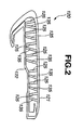
- Figure 2 is a sectional view taken along the line I-I of Figure 1 ;
- Figure 3 is a top plan view of the vehicle, in the first embodiment, as viewed from VIEW-A of Figure 1 ;
- Figure 4 is an enlarged view showing a first skin rib and a second skin rib in the first embodiment
- Figure 5 is a F-S diagram showing the relationship between a reaction F and a stroke S of a skin section in the first embodiment
- Figure 6 is an imaginary view showing the deformation of a projection section in the first embodiment
- Figure 7 is an imaginary view showing a human body structure
- Figure 8 is a top plan view of the vehicle, in a second embodiment, corresponding to that as viewed from VIEW-A of Figure 1 ;
- Figure 9 is a sectional view taken along the line II-II of Figure 8 ;
- Figure 10 is a sectional view taken along the line III-III of Figure 8 ;
- Figure 11 is an imaginary view showing the deformation of a projection section in the second embodiment.
- a configuration of a support structure 100 in the first embodiment will be discussed.
- a support structure 100 in a first embodiment may include a contact surface 120, and a set of ribs 125 serving as first projection sections and a set of ribs 135 serving as second projection sections, which may be disposed on a backside (or underside) of contact surface 120, as shown in Figures 1 and 2 .
- contact surface 120 may be fixed to a door trim 110 and may be assembled to a door panel (not shown) as a single body with door trim 110.
- Contact surface 120 may include a skin section 121 (which may be a surface of contact) and a base section 122.
- Ribs 125 and ribs 135 may be formed as projections extending from the backside surface of skin section 121 toward base section 122 and may be located between skin section 121 and base section 122. Ribs 125 and 135 may be regularly located and/or spaced adjacent to and separate from each other in such a manner so as not to contact with each other when in a relaxed position (non-compressed and/or non-collapsed position).
- Figure 2 shows a cross-sectional view along I-I of Figure 1 .
- ribs 125 and 135 are shown in the relaxed position, in which there is no contact between the ribs 125 and 135.
- Figure 3 shows a top-view from View-A of Figure 1 .
- ribs 125 and 135 are shown in the relaxed position, in which no contact is made between ribs 125 and 135.
- arrows notated at X1 and X2 show the direction in which ribs 125 and 135, respectively, may collapse or deform when a load may be applied to skin section 121 of contact surface 120.
- rib 125 may be inclined from a rib base section 126 toward a rib tip end 127. Rib tip end 127 may be in contact with base section 122.
- the inclination direction of rib 125 may be such that rib 125 may have an inclination angle ⁇ 1 relative to a vertical direction (shown as dashed line 141 of Figure 4 ).
- First inclination angle ⁇ 1 may be set at such an angle that rib 125 may be released from a forming mold without being damaged after skin section 121 may be formed.
- inclination angle ⁇ 1 may be between 15 degrees and 30 degrees.
- inclination angle ⁇ 1 is not limited to this particular range and may be suitably set, taking account of performances and characteristics of forming molds and materials.
- R (radius-based) shapes may be formed at the surface of each rib base section 126 and may be located between the rib base section 126 and skin section 121.
- the R shape on the opposite side (outside) to the side of a collapse direction X1 of each rib 125 is represented as R11 while the R shape on the side (inside) of collapse direction X1 of each rib 125 is represented as R12.
- R shape R11 may be formed larger than R shape R12, and an outside of rib base section 126 may be formed thicker than an inside of the same, as shown in Figure 4 . Accordingly, when a load may be applied to skin section 121, rib 125 may be guided to begin to deform and collapse toward rib 135.
- Rib tip end 127 may be shaped round and formed semicircular, so that rib 125 may be in slidable contact with and move on base section 122. Further, rib 125 may take the shape of a flat plate and may be tapered in width from skin rib base section 126 toward rib tip end 127. As a result, the initiation of the collapse of skin rib 125 may be softened thereby making it possible to obtain a softness feeling.
- Skin rib 135 may be inclined from rib base section 136 toward rib tip end 137, as shown in Figure 4 .
- Rib tip end 137 may be in contact with base section 122.
- the inclination direction of rib 135 may be such that rib 135 may have an inclination angle ⁇ 2 relative to a vertical direction (shown as dashed vertical line 141) so that the rib 135 may be opposite to rib 125.
- a direction of inclination 138 of rib 136 and a direction of inclination 128 of rib 125 may intersect each other at an approximately intermediate position between rib 125 and rib 135 (intersection point 140), as shown in Figure 4 .
- Inclination angle ⁇ 2 may be set at such an angle that rib 135 may be released from a forming mold without being damaged after skin section 121 may be formed. According to one or more embodiments of the present disclosure, inclination angle ⁇ 2 may be between 15 degrees and 30 degrees. However, inclination angle ⁇ 2 is not limited to this particular range and may be suitably set, taking account of performances and characteristics of forming molds and materials.
- R (radius-based) shapes may be formed at the surface of rib base section 136 and may be located between rib base section 136 and skin section 121.
- the R shape on the opposite side (outside) to the side of a collapse direction X2 of rib 135 is represented as R14 while the R shape on the side (inside) of collapse direction X2 of rib 135 is represented as R13.
- R shape R14 may be formed larger than R shape R13. Accordingly, when a load may be applied to skin section 121, rib 135 may be guided to deform in a direction toward rib 125. Rib tip end 137 may be shaped round and formed semicircular, so that rib 135 may be in slidable contact with and move on base section 122.
- rib 135 may take the shape of a flat plate and may be tapered from rib base section 136 toward rib tip end 137. As a result, the initiation of the collapse of rib 135 may be smooth thereby making it possible to obtain a softness feeling.
- a direction in which rib 125 deforms while collapsing (or deforming) may be a collapse direction X1, i . e ., a direction toward an imaginary line 141 which extends from an intersection point 140 at which a direction of inclination 128 and a direction of inclination 138 intersect and may be perpendicular to skin section 121, as shown in Figure 4 .
- a collapse direction X2 in which rib 135 may collapse may be a direction toward imaginary line 141 and may be a direction opposite of collapse direction X1.
- Rib 125 and rib 135 may be formed of plastic such as TPO, PVC, TPU and/or the like, or any other suitable material known in the art which may allow for plastic deformation or collapse.
- a pitch P1 may be a distance between rib base section 126 and rib base section 136, whereas a pitch P2 may be a distance between rib tip end 127 and rib tip end 137.
- pitch P1 may be set larger (or wider) than pitch P2.
- a ratio P2/P1 may be set between 0.35 and 0.7, however, those skilled in the art will appreciate that other ratios may be used without deviating from the scope of the present disclosure. With a set ratio P2/P1 configured, rib tip end 127 and rib tip end 137 may bend without a buckling feeling and/or a bottom-reaching feeling. Accordingly, it may be possible to obtain a stable softness feeling.
- a contact surface in accordance with one or more embodiments of the present disclosure may provide a softness feeling to the arm of an occupant. Particularly, when an arm of an occupant may be rested upon the contact surface, the contact surface may depress and/or deform. Ribs in accordance with one or more embodiments of the present disclosure may allow for a reduced impact to the arm of an occupant as applied from the contact surface into the arm of the occupant.
- Figure 5 represents the relationship between a reaction force F applied to an arm of an occupant and a moving stroke S of a skin section 121 as a force-stroke (F-S) diagram.
- the F-S diagram of Figure 5 shows a two-stage elastic deformation, in which a first stage is an initial deflection range in which reaction force F is between 0 and force F1 at which point rib 125 and rib 135 may be brought into contact with each other.
- a second stage of the F-S diagram is a secondary deflection range in which the reaction force F is not less than F1 after rib 125 and rib 135 may be brought into contact with each other.
- reaction force F1 at the inflection point may be set near a load with which a person's arm may bend, i . e ., the flesh of an elbow strikes against a bone, upon pushing an arm of a typical body of male and female persons in twenties and thirties who seem to be relatively high in sensitivity of tactile impression, with a flat pressure member having a diameter of 20 mm (1 mm/sec.), as shown in Figure 7 .
- reaction force F1 may be set at 1N to 3N, however, those skilled in the art will appreciate that the reaction force F1 may be set to other amounts of reaction force, without deviating from the scope of the present disclosure.
- the reaction force in the initial deflection range may be set to be within a range where a softness with which the occupant's arm sinks into the contact surface 120 upon coming into contact with skin section 121 may be felt in tactile impression.
- the reaction force in the secondary deflection range may be set larger than the reaction force in the initial deflection range and within a range where the arm may be supported without a bottom-reaching feeling and preventing the tactile impression sensitivity from being weakened.
- a change of rate of reaction force F to moving stroke S of skin section 121 in the initial deflection range may be set smaller than that in the secondary deflection range. Accordingly, a softness and/or low impact feeling may be provided to an occupant in the initial deflection range whereas a feeling for stably supporting the arm may be provided to the occupant in the secondary deflection range.
- rib 125 and rib 135 may be inclined in directions to be opposite to each other, as discussed above, and rib tip end 127 and rib tip end 137 may tend to deform in directions to come into contact with each other because each of the outsides of rib base section 127 and rib base section 136 may be formed thick. Additionally, rib tip end 127 and rib tip end 137 may be formed nearly semicircular, and therefore rib tip ends 127 and 137 may smoothly move on base section 122, thereby making it possible to generate a stable and smooth reaction.
- rib tip end 127 and rib tip end 137 may contact and may therefore prevent complete collapse of ribs 125 and 135.
- the contacting condition may correspond to the condition of the inflection point S1 shown in Figure 5 .
- rib tip end 127 and rib tip end 137 may bend as a one-piece body, which may serve as the second deflection range shown in Figure 5 .
- a desired softness or low impact feeling may be provided to an occupant while the occupant's arm may be stably supported, and a bottom-reaching feeling may be avoided, regardless of assembly accuracy for parts.
- Support structure 200 for a vehicle may include a contact surface 220, and a plurality of ribs 225 and ribs 235 disposed on an underside of contact surface 220.
- contact surface 220 may have ribs 225 and ribs 235 formed as projections extending from a backside surface of a skin section 221 toward a base section 222 and may be regularly located and/or spaced adjacent to each other in such a manner as not to contact with each other, as shown in Figures 8-10 .
- rib 225 may be inclined from a rib base section 226 toward a rib tip end 227, as shown in Figure 9 .
- Rib tip end 227 may be in contact with base section 222.
- An inclination direction of rib 225 may be such that rib 225 may be inclined by an inclination angle ⁇ 21 relative to a vertical direction (shown as vertical dashed line 226 of Figure 9 ).
- rib 235 may be inclined from a rib base section 236 toward a rib tip end 237, as shown in Figure 10 .
- Rib tip end 237 may be in contact with base section 222.
- An inclination direction of rib 235 may be such that the rib 235 may be inclined by an inclination angle ⁇ 22 relative to a vertical direction (shown as vertical dashed line 236 of Figure 10 ).
- a collapse direction X21 may serve as a first collapse direction and a collapse direction X22 may serve as a second collapse direction.
- Collapse directions X21 and X22 may be formed such that a direction of inclination of each collapse direction X21 and X22 may intersect each other at nearly right angles, as shown in Figure 8 .
- skin section 221 may depress (or deform) toward base section 222 under a load applied from the arm of the occupant to the skin section 221, so that rib 225 may collapse or deform in a collapse direction X21 while rib 235 may collapse or deform in a collapse direction X22, in which a condition of Figure 11A may be changed into a condition of Figure 11B .
- rib 235 may contact the side of rib 235, so that the ribs 225 and 235 may deform and bend restricting complete collapse of the ribs 225 and 235. Accordingly, a softness or low impact feeling may be provided to an occupant.
- embodiments of the present disclosure are not limited to the above-mentioned ones, as a variety of other embodiments may be employed.
- a passenger compartment such as an instrument panel, a roof panel and the like which may be touched by an occupant.
- embodiments of the present disclosure may be used for a surface structure of any parts and/or surfaces which may be desired to have soft or low impact contact, such as the interior parts of tramcars, airplanes, ships or the like, office supplies, architectural materials, furniture.
- collapse direction X1 and collapse direction X2 may be formed at any angles if they intersect each other.
- the ribs of the contact surface may be inclined, respectively, from their base sections, in the above embodiments, they may take structures in which the ribs vertically project from the skin sections without being inclined at their base sections and may be inclined from any intermediate portion and/or section.
Landscapes
- Engineering & Computer Science (AREA)
- Mechanical Engineering (AREA)
- Aviation & Aerospace Engineering (AREA)
- Transportation (AREA)
- Vehicle Interior And Exterior Ornaments, Soundproofing, And Insulation (AREA)
- Seats For Vehicles (AREA)
- Instrument Panels (AREA)
Abstract
Description
- This invention relates to a surface structure of an article for providing a low impact or softness feeling to the article.
- A Japanese patent provisional publication No.
2000-85434 - In a conventional surface structure, a rib may be formed on the backside of a contact surface while a projection may be formed on a core section which is designed to receive the contact surface when the contact surface is depressed. To achieve this a precise locational relationship is required for assembling the tip position of the rib and the projection so that a desired soft feeling may be obtained, which may be difficult to achieve with a high precision.
- A contact surface (such as a surface structure or skin) of an article, according to one or more embodiments of the present disclosure, may include a first projection section inclined in a first direction and may be located separate from a second projection section inclined in a second direction. The two projection sections may be inclined so that a direction of inclination of the two projections intersects. Upon the contact surface being pressed, the respective projection sections deform (or collapse) to approach each other and may come into contact with each other, thereby restricting complete collapse of the projections, and thereby maintaining a soft feeling and decreasing an impact force.
- According to one or more embodiments of the present disclosure, the first projection section and the second projection section may deform and may come into contact with each other so as to restrict complete collapse of the projections, thereby providing a softness feeling. As a result, the softness feeling may be stably obtained regardless of assembly accuracy among parts. Accordingly, no rib-projection combination and/or alignment, requiring precise installation, may be required.
- In one aspect, one or more embodiments of the present disclosure relate to a support structure including a contact surface configured to deform, a base section configured to receive the contact surface, a first set of ribs extending from the contact surface toward the base section and inclined in a first direction, and a second set of ribs extending from the contact surface toward the base section and inclined in a second direction, in which the first set of ribs and the second set of ribs are disposed such that there is no contact with each other in a relaxed position, and in which the first set of ribs and the second set of ribs are configured to deform and contact each other upon application of a force to the contact surface.
- In another aspect, one or more embodiments of the present disclosure relate to a support structure including a contact surface configured to deform, a base section configured to receive the contact surface, a first means for softening a deformation of the contact surface disposed on the contact surface, and a second means for softening a deformation of the contact surface disposed on the contact surface, in which the first and second means for softening are disposed such that the first means and second means for softening have no contact in a relaxed position, and in which the first and second means for softening contact upon deformation of the contact surface or upon application of a force to the contact surface.
- In another aspect, one or more embodiments of the present disclosure relates to a method to make a support structure including disposing a first set of ribs on a contact surface in a first direction, and disposing a second set of ribs on the contact surface in a second direction, in which the first set of ribs and the second set of ribs are not in contact in a relaxed position, and in which the first set of ribs and the second set of ribs are in contact in a deformed position.
- Additional embodiments of the present disclosure are defined by attached dependent claims.
-
Figure 1 is a side view of a vehicle in accordance with embodiments of the present disclosure, showing an interior part for a vehicle; -
Figure 2 is a sectional view taken along the line I-I ofFigure 1 ; -
Figure 3 is a top plan view of the vehicle, in the first embodiment, as viewed from VIEW-A ofFigure 1 ; -
Figure 4 is an enlarged view showing a first skin rib and a second skin rib in the first embodiment; -
Figure 5 is a F-S diagram showing the relationship between a reaction F and a stroke S of a skin section in the first embodiment; -
Figure 6 is an imaginary view showing the deformation of a projection section in the first embodiment; -
Figure 7 is an imaginary view showing a human body structure; -
Figure 8 is a top plan view of the vehicle, in a second embodiment, corresponding to that as viewed from VIEW-A ofFigure 1 ; -
Figure 9 is a sectional view taken along the line II-II ofFigure 8 ; -
Figure 10 is a sectional view taken along the line III-III ofFigure 8 ; and -
Figure 11 is an imaginary view showing the deformation of a projection section in the second embodiment. - Hereinafter, a first embodiment of the present disclosure will be discussed with reference to the drawings.
- A configuration of a
support structure 100 in the first embodiment will be discussed. - A
support structure 100 in a first embodiment may include acontact surface 120, and a set ofribs 125 serving as first projection sections and a set ofribs 135 serving as second projection sections, which may be disposed on a backside (or underside) ofcontact surface 120, as shown inFigures 1 and2 . - Referring to
Figures 1-3 ,contact surface 120 may be fixed to adoor trim 110 and may be assembled to a door panel (not shown) as a single body withdoor trim 110.Contact surface 120 may include a skin section 121 (which may be a surface of contact) and abase section 122.Ribs 125 andribs 135 may be formed as projections extending from the backside surface ofskin section 121 towardbase section 122 and may be located betweenskin section 121 andbase section 122.Ribs -
Figure 2 shows a cross-sectional view along I-I ofFigure 1 . InFigure 2 ,ribs ribs Figure 3 shows a top-view from View-A ofFigure 1 . Again,ribs ribs skin section 121 ofcontact surface 120. - Now referring to
Figure 4 ,rib 125 may be inclined from arib base section 126 toward arib tip end 127.Rib tip end 127 may be in contact withbase section 122. The inclination direction ofrib 125 may be such thatrib 125 may have an inclination angle θ1 relative to a vertical direction (shown as dashedline 141 ofFigure 4 ). First inclination angle θ1 may be set at such an angle thatrib 125 may be released from a forming mold without being damaged afterskin section 121 may be formed. According to one or more embodiments of the present disclosure, inclination angle θ1 may be between 15 degrees and 30 degrees. However, inclination angle θ1 is not limited to this particular range and may be suitably set, taking account of performances and characteristics of forming molds and materials. - Additionally, R (radius-based) shapes may be formed at the surface of each
rib base section 126 and may be located between therib base section 126 andskin section 121. The R shape on the opposite side (outside) to the side of a collapse direction X1 of eachrib 125 is represented as R11 while the R shape on the side (inside) of collapse direction X1 of eachrib 125 is represented as R12. R shape R11 may be formed larger than R shape R12, and an outside ofrib base section 126 may be formed thicker than an inside of the same, as shown inFigure 4 . Accordingly, when a load may be applied toskin section 121,rib 125 may be guided to begin to deform and collapse towardrib 135.Rib tip end 127 may be shaped round and formed semicircular, so thatrib 125 may be in slidable contact with and move onbase section 122. Further,rib 125 may take the shape of a flat plate and may be tapered in width from skinrib base section 126 towardrib tip end 127. As a result, the initiation of the collapse ofskin rib 125 may be softened thereby making it possible to obtain a softness feeling. -
Skin rib 135 may be inclined fromrib base section 136 towardrib tip end 137, as shown inFigure 4 .Rib tip end 137 may be in contact withbase section 122. The inclination direction ofrib 135 may be such thatrib 135 may have an inclination angle θ2 relative to a vertical direction (shown as dashed vertical line 141) so that therib 135 may be opposite to rib 125. In other words, a direction ofinclination 138 ofrib 136 and a direction ofinclination 128 ofrib 125 may intersect each other at an approximately intermediate position betweenrib 125 and rib 135 (intersection point 140), as shown inFigure 4 . Inclination angle θ2 may be set at such an angle thatrib 135 may be released from a forming mold without being damaged afterskin section 121 may be formed. According to one or more embodiments of the present disclosure, inclination angle θ2 may be between 15 degrees and 30 degrees. However, inclination angle θ2 is not limited to this particular range and may be suitably set, taking account of performances and characteristics of forming molds and materials. - Additionally, R (radius-based) shapes may be formed at the surface of
rib base section 136 and may be located betweenrib base section 136 andskin section 121. The R shape on the opposite side (outside) to the side of a collapse direction X2 ofrib 135 is represented as R14 while the R shape on the side (inside) of collapse direction X2 ofrib 135 is represented as R13. R shape R14 may be formed larger than R shape R13. Accordingly, when a load may be applied toskin section 121,rib 135 may be guided to deform in a direction towardrib 125.Rib tip end 137 may be shaped round and formed semicircular, so thatrib 135 may be in slidable contact with and move onbase section 122. Further,rib 135 may take the shape of a flat plate and may be tapered fromrib base section 136 towardrib tip end 137. As a result, the initiation of the collapse ofrib 135 may be smooth thereby making it possible to obtain a softness feeling. - According to one or more embodiments of the present disclosure, a direction in which
rib 125 deforms while collapsing (or deforming) may be a collapse direction X1, i.e., a direction toward animaginary line 141 which extends from anintersection point 140 at which a direction ofinclination 128 and a direction ofinclination 138 intersect and may be perpendicular toskin section 121, as shown inFigure 4 . A collapse direction X2 in whichrib 135 may collapse may be a direction towardimaginary line 141 and may be a direction opposite of collapse direction X1.Rib 125 andrib 135 may be formed of plastic such as TPO, PVC, TPU and/or the like, or any other suitable material known in the art which may allow for plastic deformation or collapse. - Additionally, a pitch P1 may be a distance between
rib base section 126 andrib base section 136, whereas a pitch P2 may be a distance betweenrib tip end 127 andrib tip end 137. As shown inFigure 4 , pitch P1 may be set larger (or wider) than pitch P2. A ratio P2/P1 may be set between 0.35 and 0.7, however, those skilled in the art will appreciate that other ratios may be used without deviating from the scope of the present disclosure. With a set ratio P2/P1 configured,rib tip end 127 andrib tip end 137 may bend without a buckling feeling and/or a bottom-reaching feeling. Accordingly, it may be possible to obtain a stable softness feeling. - As applied to an arm rest of a vehicle, a contact surface in accordance with one or more embodiments of the present disclosure may provide a softness feeling to the arm of an occupant. Particularly, when an arm of an occupant may be rested upon the contact surface, the contact surface may depress and/or deform. Ribs in accordance with one or more embodiments of the present disclosure may allow for a reduced impact to the arm of an occupant as applied from the contact surface into the arm of the occupant.
-
Figure 5 represents the relationship between a reaction force F applied to an arm of an occupant and a moving stroke S of askin section 121 as a force-stroke (F-S) diagram. The F-S diagram ofFigure 5 shows a two-stage elastic deformation, in which a first stage is an initial deflection range in which reaction force F is between 0 and force F1 at whichpoint rib 125 andrib 135 may be brought into contact with each other. A second stage of the F-S diagram is a secondary deflection range in which the reaction force F is not less than F1 afterrib 125 andrib 135 may be brought into contact with each other. Additionally, a point at which a changeover may be made between the initial deflection range and second deflection range is an inflection point, noted at S1. Here, the reaction force F1 at the inflection point may be set near a load with which a person's arm may bend, i.e., the flesh of an elbow strikes against a bone, upon pushing an arm of a typical body of male and female persons in twenties and thirties who seem to be relatively high in sensitivity of tactile impression, with a flat pressure member having a diameter of 20 mm (1 mm/sec.), as shown inFigure 7 . In this embodiment, reaction force F1 may be set at 1N to 3N, however, those skilled in the art will appreciate that the reaction force F1 may be set to other amounts of reaction force, without deviating from the scope of the present disclosure. - In accordance with one or more embodiments of the present disclosure, the reaction force in the initial deflection range may be set to be within a range where a softness with which the occupant's arm sinks into the
contact surface 120 upon coming into contact withskin section 121 may be felt in tactile impression. Additionally, the reaction force in the secondary deflection range may be set larger than the reaction force in the initial deflection range and within a range where the arm may be supported without a bottom-reaching feeling and preventing the tactile impression sensitivity from being weakened. Further, a change of rate of reaction force F to moving stroke S ofskin section 121 in the initial deflection range may be set smaller than that in the secondary deflection range. Accordingly, a softness and/or low impact feeling may be provided to an occupant in the initial deflection range whereas a feeling for stably supporting the arm may be provided to the occupant in the secondary deflection range. - Next, deformation of
contact surface 120 in accordance with one or more embodiments of the present disclosure will be discussed with reference toFigures 6A-6C . - When an occupant may put his arm on
contact surface 120,skin section 121 may be depressed (or deformed) towardbase section 122 under a load f applied from the arm of the occupant to the skin section 121 (seeFigure 6B ). Upon application of load f,rib 125 andrib 135 may bend or deform toward each other so as to form an arcuate shape upon being in contact with each other (seeFigure 6C ). Accordingly, the condition as shown inFigure 6A may be changed into a condition as shown inFigure 6B , which may correspond to the initial deflection range shown inFigure 5 . At this time,rib 125 andrib 135 may be inclined in directions to be opposite to each other, as discussed above, andrib tip end 127 andrib tip end 137 may tend to deform in directions to come into contact with each other because each of the outsides ofrib base section 127 andrib base section 136 may be formed thick. Additionally,rib tip end 127 andrib tip end 137 may be formed nearly semicircular, and therefore rib tip ends 127 and 137 may smoothly move onbase section 122, thereby making it possible to generate a stable and smooth reaction. - Further, as shown in
Figure 6C ,rib tip end 127 andrib tip end 137 may contact and may therefore prevent complete collapse ofribs Figure 5 . Further, afterrib tip end 127 andrib tip end 137 contact with each other,rib tip end 127 andrib tip end 137 may bend as a one-piece body, which may serve as the second deflection range shown inFigure 5 . Thus, in accordance with one or more embodiments disclosed herein, a desired softness or low impact feeling may be provided to an occupant while the occupant's arm may be stably supported, and a bottom-reaching feeling may be avoided, regardless of assembly accuracy for parts. - Hereafter, a second embodiment of the present disclosure will be discussed with reference to
Figures 8-11 . - An arrangement of a
support structure 200, according to one or more embodiments of the present disclosure will be discussed. - Discussion of
support structure 200, in the second embodiment will be made only for parts different from those of the first embodiment, omitting discussion for parts similar to those of the first embodiment. -
Support structure 200 for a vehicle may include acontact surface 220, and a plurality ofribs 225 andribs 235 disposed on an underside ofcontact surface 220. - As shown in
Figures 8-10 ,contact surface 220 may haveribs 225 andribs 235 formed as projections extending from a backside surface of askin section 221 toward abase section 222 and may be regularly located and/or spaced adjacent to each other in such a manner as not to contact with each other, as shown inFigures 8-10 . - Referring to
Figure 9 (a cross-sectional view ofFigure 8 along the line II-II),rib 225 may be inclined from arib base section 226 toward arib tip end 227, as shown inFigure 9 .Rib tip end 227 may be in contact withbase section 222. An inclination direction ofrib 225 may be such thatrib 225 may be inclined by an inclination angle θ21 relative to a vertical direction (shown as vertical dashedline 226 ofFigure 9 ). - Referring to
Figure 10 (a cross-sectional view ofFigure 8 along the line III-III),rib 235 may be inclined from arib base section 236 toward arib tip end 237, as shown inFigure 10 .Rib tip end 237 may be in contact withbase section 222. An inclination direction ofrib 235 may be such that therib 235 may be inclined by an inclination angle θ22 relative to a vertical direction (shown as vertical dashedline 236 ofFigure 10 ). - According to one or more embodiments of the present disclosure, a collapse direction X21 may serve as a first collapse direction and a collapse direction X22 may serve as a second collapse direction. Collapse directions X21 and X22 may be formed such that a direction of inclination of each collapse direction X21 and X22 may intersect each other at nearly right angles, as shown in
Figure 8 . - Next, deformation of
arm rest 220 according to one or more embodiments of the present disclosure will be discussed with reference toFigures 11A and 11B . - When an occupant may put his arm on
contact surface 220,skin section 221 may depress (or deform) towardbase section 222 under a load applied from the arm of the occupant to theskin section 221, so thatrib 225 may collapse or deform in a collapse direction X21 whilerib 235 may collapse or deform in a collapse direction X22, in which a condition ofFigure 11A may be changed into a condition ofFigure 11B . As shown inFigure 11B ,rib 235 may contact the side ofrib 235, so that theribs ribs - The same effects as in the first embodiment may be obtained in the second embodiment, as discussed above.
- The embodiments of the present disclosure are not limited to the above-mentioned ones, as a variety of other embodiments may be employed. For example, it may be possible to apply embodiments the present disclosure to interior parts in a passenger compartment, such as an instrument panel, a roof panel and the like which may be touched by an occupant. Additionally, embodiments of the present disclosure may be used for a surface structure of any parts and/or surfaces which may be desired to have soft or low impact contact, such as the interior parts of tramcars, airplanes, ships or the like, office supplies, architectural materials, furniture. Additionally, collapse direction X1 and collapse direction X2 may be formed at any angles if they intersect each other. Additionally, while the ribs of the contact surface may be inclined, respectively, from their base sections, in the above embodiments, they may take structures in which the ribs vertically project from the skin sections without being inclined at their base sections and may be inclined from any intermediate portion and/or section.
Claims (21)
- A support structure (100; 200), the support structure comprising:a contact surface (120; 220) configured to deform;a base section (122; 222) configured to receive the contact surface (120; 220);a first means for softening a deformation of the contact surface (120; 220) disposed on the contact surface (120; 220); anda second means for softening a deformation of the contact surface (120; 220) disposed on the contact surface (120; 220),wherein the first and second means for softening are disposed such that the first means and second means for softening have no contact in a relaxed position, andwherein the first and second means for softening contact upon deformation of the contact surface (120; 220) or upon application of a force to the contact surface (120; 220).
- The support structure (100; 200) of claim 1,
wherein the first means for softening is inclined in a first direction (128),
wherein the second means for softening is inclined in a second direction (138), and
wherein the first direction (128) and the second direction (138) are inclined towards each
other. - The support structure of claim 1,
wherein the first means for softening is inclined in a first direction,
wherein the second means for softening is inclined in a second direction, and
wherein the first direction and the second direction are inclined perpendicular each other. - The support structure (100; 200) of any of claims 1-3, wherein the first means for softening and the second means for softening comprise a first projection section and a second projection section respectively.
- The support structure (100; 200) of any of claims 1-4, wherein the first means for
softening and the second means for softening comprise
a first set of ribs (125; 225) extending from the contact surface (120; 220) toward the base section (122; 222); and
a second set of ribs (135; 235) extending from the contact surface (120; 220) toward the base section (122; 222) respectively,
wherein the first set of ribs (125; 225) and the second set of ribs (135; 235) are configured to
deform and contact each other upon application of a force to the contact surface (120; 220). - The support structure (100) of claim 5, further comprising:a first pitch (P1) configured to be a distance between a base (126) of a rib of the first set of ribs (125) and a base (136) of a rib of the second set of ribs (135); and
a second pitch (P2) configured to be a distance between a tip (127) of the rib of the first set of ribs(125) and a tip (137) of the rib of the second set of ribs (135),andwherein the first pitch (P1) is larger than the second pitch (P2). - The support structure (100) of claim 6, wherein a ratio of the second pitch (P2) to the first pitch (P1) is between 0.35 and 0.70.
- The support structure (100; 200) of claim 5, wherein the ribs of the first set of ribs (125; 225) and the ribs of the second set of ribs (135; 235) are tapered such that a base (126, 136; 226) thickness of the ribs is larger than a tip (127, 137; 227) thickness of the ribs.
- The support structure of claim 8, wherein the base thickness is unequal, such that a base thickness on a first side of the rib is thicker than a base thickness on a second side of the rib.
- The support structure (100; 200) of claim 5, wherein tips (127, 137; 227) of at least one of the ribs of the first set of ribs (125; 225) and second set of ribs (135; 235) are rounded.
- The support structure of claim 5, wherein the ribs of at least one of the ribs of the first set of ribs and the second set of ribs are plate shaped.
- The support structure of claim 5, further comprising:a point of contact between ribs of the first set of ribs and the ribs of the second set of ribs,wherein a reaction force of the support structure during deformation prior to the ribs reaching
the point of contact is less than a reaction force of the support structure after reaching the point of contact. - The support structure of claim 5, wherein the support structure comprises an arm rest for a vehicle.
- A method to make a support structure (100; 200), the method comprising:disposing a first means for softening a deformation of a contact surface (120; 220)on a contact surface (120; 220)in a first direction (128); anddisposing a second means for softening a deformation of the contact surface(120; 220) on the contact surface (120; 220) in a second direction (138);wherein the first means for softening and the second means for softening are not in contact in a relaxed position, andwherein the first means for softening and the second means for softening are in contact in a deformed position.
- The method of claim 14, wherein the first direction (128) and the second direction (138) are inclined toward each other.
- The method of claim 14, wherein the first direction and the second direction are inclined perpendicular to each other.
- The method of any of claims 14-16, wherein the first means for softening and the second means for softening comprise a first projection section and a second projection section respectively.
- The method of any of claims 14-17, wherein the first means for softening and the second means for softening comprise a first set of ribs (125; 225) extending from the contact surface (120; 220) toward the base section and a second set of ribs (135; 235) extending from the contact surface (120; 220) toward the base section respectively, wherein the first set of ribs (125; 225) and the second set of ribs (135; 235) are configured to deform and contact each other upon application of a force to the contact surface (120; 220).
- The method of claim 18, further comprising:placing the contact surface (135; 235) over a base section,wherein the first set of ribs (125; 225) and the second set of ribs (135; 235) are configured to
contact the base section. - The method of claim 18, wherein the first set of ribs (125; 225) is disposed a distance from the second set of ribs (135; 235) such that a ratio of a distance (P1) between a base (126; 226) of a rib of the first set of ribs (125; 225) to a base (136; 226) of a rib of the second set of ribs (135; 235) to a distance (P2) between a tip (127; 227) of the rib of the first set of ribs to a tip (137; 227) of the rib of the second set of ribs (135; 235) is between 0.35 and 0.70.
- The method of claim 18, further comprising:installing the contact surface (120; 220) in a vehicle.
Applications Claiming Priority (1)
| Application Number | Priority Date | Filing Date | Title |
|---|---|---|---|
| JP2009102662A JP5299055B2 (en) | 2009-04-21 | 2009-04-21 | Interior parts for vehicles |
Publications (2)
| Publication Number | Publication Date |
|---|---|
| EP2243658A1 true EP2243658A1 (en) | 2010-10-27 |
| EP2243658B1 EP2243658B1 (en) | 2017-02-22 |
Family
ID=42338165
Family Applications (1)
| Application Number | Title | Priority Date | Filing Date |
|---|---|---|---|
| EP10157389.7A Not-in-force EP2243658B1 (en) | 2009-04-21 | 2010-03-23 | A support structure |
Country Status (4)
| Country | Link |
|---|---|
| US (1) | US8157309B2 (en) |
| EP (1) | EP2243658B1 (en) |
| JP (1) | JP5299055B2 (en) |
| CN (1) | CN101870275B (en) |
Cited By (6)
| Publication number | Priority date | Publication date | Assignee | Title |
|---|---|---|---|---|
| EP2826619A4 (en) * | 2012-03-07 | 2015-12-30 | Toyota Tekko Kk | SUPERIOR COMPOSITE ELEMENT |
| EP2930015A4 (en) * | 2012-12-06 | 2016-08-10 | Toyota Tekko Kk | Multi-layer composite part |
| WO2017017538A1 (en) * | 2015-07-28 | 2017-02-02 | Thule Sweden Ab | Support pad for a load carrier |
| US9815418B2 (en) | 2013-05-15 | 2017-11-14 | Toyoda Iron Works Co., Ltd. | Laminated composite interior part |
| EP3150441A4 (en) * | 2014-05-26 | 2018-01-24 | Toyoda Iron Works Co., Ltd. | Overlaid composite interior component |
| EP3330133A4 (en) * | 2015-07-28 | 2019-02-27 | Toyoda Iron Works Co., Ltd. | STACKED COMPOSITE COMPONENT |
Families Citing this family (21)
| Publication number | Priority date | Publication date | Assignee | Title |
|---|---|---|---|---|
| US8454053B2 (en) * | 2010-02-25 | 2013-06-04 | Ford Global Technologies, Llc | Energy absorbing structure for vehicle knee bolster cover |
| WO2014077074A1 (en) * | 2012-11-16 | 2014-05-22 | 日産自動車株式会社 | Skin material |
| JP5950814B2 (en) * | 2012-12-26 | 2016-07-13 | 豊田鉄工株式会社 | Overlapped composite parts |
| EP3045305B1 (en) * | 2013-09-13 | 2020-08-19 | Toyoda Iron Works Co., Ltd. | Multilayer composite interior component |
| US9266489B2 (en) * | 2013-10-28 | 2016-02-23 | Toyota Motor Engineering & Manufacturing North America, Inc. | Vehicle door energy absorption pad |
| US9254765B2 (en) | 2013-12-17 | 2016-02-09 | Ford Global Technologies, Llc | Vehicle armrest with structural fabric substrate |
| US9925897B2 (en) | 2013-12-17 | 2018-03-27 | Ford Global Technologies, Llc | Door trim armrest substrate structure |
| US9463723B2 (en) | 2014-04-07 | 2016-10-11 | Ford Global Technologies, Llc | Armrest substrate having detachable elongated support bands |
| US9610873B2 (en) | 2014-04-25 | 2017-04-04 | Ford Global Technologies, Llc | Fully collapsing armrest insert with tunable tensioning elements |
| JP6131233B2 (en) * | 2014-10-24 | 2017-05-17 | 豊田鉄工株式会社 | Stacked composite interior parts |
| JP2016107840A (en) * | 2014-12-05 | 2016-06-20 | 豊田鉄工株式会社 | Vehicle interior panel |
| US10293762B2 (en) | 2014-11-26 | 2019-05-21 | Toyota Iron Works Co., Ltd. | Vehicular interior component, vehicular interior panel, and vehicular composite interior component |
| US9505325B2 (en) | 2014-12-11 | 2016-11-29 | Ford Global Technologies, Llc | Energy absorbing collapsible armrest with tunable stiffening feature |
| JP2017007494A (en) * | 2015-06-22 | 2017-01-12 | 豊田鉄工株式会社 | Cushion structure |
| US10065547B2 (en) * | 2016-09-21 | 2018-09-04 | Ford Global Technologies Llc | Armrest support bridge |
| US10336228B2 (en) * | 2017-03-14 | 2019-07-02 | Ford Global Technologies Pllc | Four-component armrest assembly and method of manufacturing same |
| JP6845185B2 (en) * | 2018-06-04 | 2021-03-17 | 豊田鉄工株式会社 | Manufacturing method of superposed composite parts and superposed composite parts |
| US10583760B2 (en) * | 2018-06-08 | 2020-03-10 | Ford Global Technologies, Llc | Armrest and support for an armrest assembly |
| JP2020132020A (en) * | 2019-02-21 | 2020-08-31 | 本田技研工業株式会社 | Vehicular cargo compartment structure |
| JP7111888B2 (en) * | 2019-03-29 | 2022-08-02 | 豊田鉄工株式会社 | Laminated interior parts |
| JP7356963B2 (en) | 2020-12-16 | 2023-10-05 | 豊田鉄工株式会社 | Armrest, which is an interior component for vehicles, and its manufacturing method |
Citations (4)
| Publication number | Priority date | Publication date | Assignee | Title |
|---|---|---|---|---|
| CH689638A5 (en) * | 1995-04-13 | 1999-07-30 | Alusuisse Lonza Services Ag | Bumper for road vehicle |
| JP2000085434A (en) | 1998-09-10 | 2000-03-28 | Kasai Kogyo Co Ltd | Arm rest for vehicle |
| WO2001058302A1 (en) * | 2000-02-10 | 2001-08-16 | 3M Innovative Properties Company | Self-mating reclosable mechanical fastener and binding strap |
| JP2004360790A (en) * | 2003-06-04 | 2004-12-24 | Jsp Corp | Energy absorbing material |
Family Cites Families (8)
| Publication number | Priority date | Publication date | Assignee | Title |
|---|---|---|---|---|
| JPS5951654U (en) * | 1982-09-30 | 1984-04-05 | 豊田合成株式会社 | hollow mold |
| JPH0671235U (en) * | 1993-03-25 | 1994-10-04 | 河西工業株式会社 | Shock absorbing structure for door trim |
| JP3228284B2 (en) * | 1994-02-22 | 2001-11-12 | トヨタ自動車株式会社 | Impact energy absorption structure by car interior materials |
| JP3255000B2 (en) * | 1996-02-19 | 2002-02-12 | 日産自動車株式会社 | Car body structure |
| JP2005153632A (en) * | 2003-11-21 | 2005-06-16 | Toyoda Gosei Co Ltd | Shock absorber for vehicle |
| US7226113B2 (en) * | 2004-12-29 | 2007-06-05 | Lear Corporation | Armrest insert and corresponding assembly for a vehicle |
| FR2900889B1 (en) * | 2006-05-09 | 2009-03-20 | Faurecia Interieur Ind Snc | FLEXIBLE TRIM FOR MOTOR VEHICLE EQUIPMENT PIECE AND EQUIPMENT PART THEREOF |
| US7775584B2 (en) * | 2008-04-14 | 2010-08-17 | Honda Motor Co., Ltd. | Impact absorbing armrest for a motor vehicle |
-
2009
- 2009-04-21 JP JP2009102662A patent/JP5299055B2/en not_active Expired - Fee Related
-
2010
- 2010-03-23 EP EP10157389.7A patent/EP2243658B1/en not_active Not-in-force
- 2010-04-15 CN CN2010101497348A patent/CN101870275B/en not_active Expired - Fee Related
- 2010-04-16 US US12/762,153 patent/US8157309B2/en not_active Expired - Fee Related
Patent Citations (4)
| Publication number | Priority date | Publication date | Assignee | Title |
|---|---|---|---|---|
| CH689638A5 (en) * | 1995-04-13 | 1999-07-30 | Alusuisse Lonza Services Ag | Bumper for road vehicle |
| JP2000085434A (en) | 1998-09-10 | 2000-03-28 | Kasai Kogyo Co Ltd | Arm rest for vehicle |
| WO2001058302A1 (en) * | 2000-02-10 | 2001-08-16 | 3M Innovative Properties Company | Self-mating reclosable mechanical fastener and binding strap |
| JP2004360790A (en) * | 2003-06-04 | 2004-12-24 | Jsp Corp | Energy absorbing material |
Cited By (9)
| Publication number | Priority date | Publication date | Assignee | Title |
|---|---|---|---|---|
| EP2826619A4 (en) * | 2012-03-07 | 2015-12-30 | Toyota Tekko Kk | SUPERIOR COMPOSITE ELEMENT |
| US9987819B2 (en) | 2012-03-07 | 2018-06-05 | Toyoda Iron Works Co., Ltd. | Superimposed composite interior component |
| EP2930015A4 (en) * | 2012-12-06 | 2016-08-10 | Toyota Tekko Kk | Multi-layer composite part |
| US9573341B2 (en) | 2012-12-06 | 2017-02-21 | Toyoda Iron Works Co., Ltd. | Multi-layer composite part |
| US9815418B2 (en) | 2013-05-15 | 2017-11-14 | Toyoda Iron Works Co., Ltd. | Laminated composite interior part |
| EP3150441A4 (en) * | 2014-05-26 | 2018-01-24 | Toyoda Iron Works Co., Ltd. | Overlaid composite interior component |
| US10330165B2 (en) | 2014-05-26 | 2019-06-25 | Toyoda Iron Works Co., Ltd. | Overlaid composite interior component |
| WO2017017538A1 (en) * | 2015-07-28 | 2017-02-02 | Thule Sweden Ab | Support pad for a load carrier |
| EP3330133A4 (en) * | 2015-07-28 | 2019-02-27 | Toyoda Iron Works Co., Ltd. | STACKED COMPOSITE COMPONENT |
Also Published As
| Publication number | Publication date |
|---|---|
| JP5299055B2 (en) | 2013-09-25 |
| CN101870275B (en) | 2013-02-13 |
| US8157309B2 (en) | 2012-04-17 |
| JP2010253967A (en) | 2010-11-11 |
| US20100264680A1 (en) | 2010-10-21 |
| EP2243658B1 (en) | 2017-02-22 |
| CN101870275A (en) | 2010-10-27 |
Similar Documents
| Publication | Publication Date | Title |
|---|---|---|
| EP2243658B1 (en) | A support structure | |
| US9424825B2 (en) | Keyboard apparatus for an electronic musical instrument | |
| EP2998109B1 (en) | Multilayer composite interior component | |
| EP3330133B1 (en) | Stacked composite interior component | |
| CN113631361B (en) | Overlapping interior components | |
| CN105531109B (en) | Coinciding Composite Interior Parts | |
| JPWO2018123560A1 (en) | Exterior panel and method for manufacturing exterior panel | |
| JP2009078142A (en) | Vehicular seat pad and its manufacturing method | |
| CN104853909A (en) | Multi-layer composite part | |
| CN107000655A (en) | Overlapping compound inside components | |
| CN109484322B (en) | Decorative piece comprising a deformable outer surface and related vehicle | |
| US20170001592A1 (en) | Airbag Covering and Method for Producing Same | |
| CN106414177B (en) | Overlapping Composite Interior Parts | |
| CN102592580A (en) | Pedal device, and electronic musical instrument including the pedal device | |
| WO2014077074A1 (en) | Skin material | |
| JP5502297B2 (en) | Seat pad | |
| JP7724537B2 (en) | Vehicle interior materials | |
| CN217035467U (en) | Sound production shell fragment | |
| JP5798432B2 (en) | Railcar body skin | |
| JPH05337580A (en) | Perforated plate | |
| JP6489329B2 (en) | Electronic musical instrument keyboard device | |
| JPH10108755A (en) | Seat cushion structure for vehicle seat | |
| JP2006264398A (en) | Car armrest | |
| JP2006290305A (en) | Interior panel for automobile |
Legal Events
| Date | Code | Title | Description |
|---|---|---|---|
| PUAI | Public reference made under article 153(3) epc to a published international application that has entered the european phase |
Free format text: ORIGINAL CODE: 0009012 |
|
| AK | Designated contracting states |
Kind code of ref document: A1 Designated state(s): AT BE BG CH CY CZ DE DK EE ES FI FR GB GR HR HU IE IS IT LI LT LU LV MC MK MT NL NO PL PT RO SE SI SK SM TR |
|
| AX | Request for extension of the european patent |
Extension state: AL BA ME RS |
|
| 17P | Request for examination filed |
Effective date: 20110427 |
|
| 17Q | First examination report despatched |
Effective date: 20120718 |
|
| GRAP | Despatch of communication of intention to grant a patent |
Free format text: ORIGINAL CODE: EPIDOSNIGR1 |
|
| STAA | Information on the status of an ep patent application or granted ep patent |
Free format text: STATUS: GRANT OF PATENT IS INTENDED |
|
| INTG | Intention to grant announced |
Effective date: 20161128 |
|
| GRAS | Grant fee paid |
Free format text: ORIGINAL CODE: EPIDOSNIGR3 |
|
| GRAA | (expected) grant |
Free format text: ORIGINAL CODE: 0009210 |
|
| STAA | Information on the status of an ep patent application or granted ep patent |
Free format text: STATUS: THE PATENT HAS BEEN GRANTED |
|
| AK | Designated contracting states |
Kind code of ref document: B1 Designated state(s): AT BE BG CH CY CZ DE DK EE ES FI FR GB GR HR HU IE IS IT LI LT LU LV MC MK MT NL NO PL PT RO SE SI SK SM TR |
|
| REG | Reference to a national code |
Ref country code: GB Ref legal event code: FG4D |
|
| REG | Reference to a national code |
Ref country code: CH Ref legal event code: EP |
|
| REG | Reference to a national code |
Ref country code: AT Ref legal event code: REF Ref document number: 869005 Country of ref document: AT Kind code of ref document: T Effective date: 20170315 |
|
| REG | Reference to a national code |
Ref country code: IE Ref legal event code: FG4D |
|
| REG | Reference to a national code |
Ref country code: FR Ref legal event code: PLFP Year of fee payment: 8 |
|
| REG | Reference to a national code |
Ref country code: DE Ref legal event code: R096 Ref document number: 602010040163 Country of ref document: DE |
|
| REG | Reference to a national code |
Ref country code: LT Ref legal event code: MG4D |
|
| REG | Reference to a national code |
Ref country code: NL Ref legal event code: MP Effective date: 20170222 |
|
| REG | Reference to a national code |
Ref country code: AT Ref legal event code: MK05 Ref document number: 869005 Country of ref document: AT Kind code of ref document: T Effective date: 20170222 |
|
| PG25 | Lapsed in a contracting state [announced via postgrant information from national office to epo] |
Ref country code: HR Free format text: LAPSE BECAUSE OF FAILURE TO SUBMIT A TRANSLATION OF THE DESCRIPTION OR TO PAY THE FEE WITHIN THE PRESCRIBED TIME-LIMIT Effective date: 20170222 Ref country code: NO Free format text: LAPSE BECAUSE OF FAILURE TO SUBMIT A TRANSLATION OF THE DESCRIPTION OR TO PAY THE FEE WITHIN THE PRESCRIBED TIME-LIMIT Effective date: 20170522 Ref country code: FI Free format text: LAPSE BECAUSE OF FAILURE TO SUBMIT A TRANSLATION OF THE DESCRIPTION OR TO PAY THE FEE WITHIN THE PRESCRIBED TIME-LIMIT Effective date: 20170222 Ref country code: LT Free format text: LAPSE BECAUSE OF FAILURE TO SUBMIT A TRANSLATION OF THE DESCRIPTION OR TO PAY THE FEE WITHIN THE PRESCRIBED TIME-LIMIT Effective date: 20170222 Ref country code: GR Free format text: LAPSE BECAUSE OF FAILURE TO SUBMIT A TRANSLATION OF THE DESCRIPTION OR TO PAY THE FEE WITHIN THE PRESCRIBED TIME-LIMIT Effective date: 20170523 |
|
| PG25 | Lapsed in a contracting state [announced via postgrant information from national office to epo] |
Ref country code: NL Free format text: LAPSE BECAUSE OF FAILURE TO SUBMIT A TRANSLATION OF THE DESCRIPTION OR TO PAY THE FEE WITHIN THE PRESCRIBED TIME-LIMIT Effective date: 20170222 Ref country code: ES Free format text: LAPSE BECAUSE OF FAILURE TO SUBMIT A TRANSLATION OF THE DESCRIPTION OR TO PAY THE FEE WITHIN THE PRESCRIBED TIME-LIMIT Effective date: 20170222 Ref country code: PT Free format text: LAPSE BECAUSE OF FAILURE TO SUBMIT A TRANSLATION OF THE DESCRIPTION OR TO PAY THE FEE WITHIN THE PRESCRIBED TIME-LIMIT Effective date: 20170622 Ref country code: LV Free format text: LAPSE BECAUSE OF FAILURE TO SUBMIT A TRANSLATION OF THE DESCRIPTION OR TO PAY THE FEE WITHIN THE PRESCRIBED TIME-LIMIT Effective date: 20170222 Ref country code: AT Free format text: LAPSE BECAUSE OF FAILURE TO SUBMIT A TRANSLATION OF THE DESCRIPTION OR TO PAY THE FEE WITHIN THE PRESCRIBED TIME-LIMIT Effective date: 20170222 Ref country code: SE Free format text: LAPSE BECAUSE OF FAILURE TO SUBMIT A TRANSLATION OF THE DESCRIPTION OR TO PAY THE FEE WITHIN THE PRESCRIBED TIME-LIMIT Effective date: 20170222 Ref country code: BG Free format text: LAPSE BECAUSE OF FAILURE TO SUBMIT A TRANSLATION OF THE DESCRIPTION OR TO PAY THE FEE WITHIN THE PRESCRIBED TIME-LIMIT Effective date: 20170522 |
|
| PG25 | Lapsed in a contracting state [announced via postgrant information from national office to epo] |
Ref country code: IT Free format text: LAPSE BECAUSE OF FAILURE TO SUBMIT A TRANSLATION OF THE DESCRIPTION OR TO PAY THE FEE WITHIN THE PRESCRIBED TIME-LIMIT Effective date: 20170222 Ref country code: CZ Free format text: LAPSE BECAUSE OF FAILURE TO SUBMIT A TRANSLATION OF THE DESCRIPTION OR TO PAY THE FEE WITHIN THE PRESCRIBED TIME-LIMIT Effective date: 20170222 Ref country code: EE Free format text: LAPSE BECAUSE OF FAILURE TO SUBMIT A TRANSLATION OF THE DESCRIPTION OR TO PAY THE FEE WITHIN THE PRESCRIBED TIME-LIMIT Effective date: 20170222 Ref country code: RO Free format text: LAPSE BECAUSE OF FAILURE TO SUBMIT A TRANSLATION OF THE DESCRIPTION OR TO PAY THE FEE WITHIN THE PRESCRIBED TIME-LIMIT Effective date: 20170222 Ref country code: SK Free format text: LAPSE BECAUSE OF FAILURE TO SUBMIT A TRANSLATION OF THE DESCRIPTION OR TO PAY THE FEE WITHIN THE PRESCRIBED TIME-LIMIT Effective date: 20170222 |
|
| REG | Reference to a national code |
Ref country code: CH Ref legal event code: PL |
|
| REG | Reference to a national code |
Ref country code: DE Ref legal event code: R097 Ref document number: 602010040163 Country of ref document: DE |
|
| REG | Reference to a national code |
Ref country code: DE Ref legal event code: R079 Ref document number: 602010040163 Country of ref document: DE Free format text: PREVIOUS MAIN CLASS: B60N0002460000 Ipc: B60N0002750000 |
|
| PG25 | Lapsed in a contracting state [announced via postgrant information from national office to epo] |
Ref country code: SM Free format text: LAPSE BECAUSE OF FAILURE TO SUBMIT A TRANSLATION OF THE DESCRIPTION OR TO PAY THE FEE WITHIN THE PRESCRIBED TIME-LIMIT Effective date: 20170222 Ref country code: DK Free format text: LAPSE BECAUSE OF FAILURE TO SUBMIT A TRANSLATION OF THE DESCRIPTION OR TO PAY THE FEE WITHIN THE PRESCRIBED TIME-LIMIT Effective date: 20170222 Ref country code: PL Free format text: LAPSE BECAUSE OF FAILURE TO SUBMIT A TRANSLATION OF THE DESCRIPTION OR TO PAY THE FEE WITHIN THE PRESCRIBED TIME-LIMIT Effective date: 20170222 Ref country code: MC Free format text: LAPSE BECAUSE OF FAILURE TO SUBMIT A TRANSLATION OF THE DESCRIPTION OR TO PAY THE FEE WITHIN THE PRESCRIBED TIME-LIMIT Effective date: 20170222 |
|
| REG | Reference to a national code |
Ref country code: IE Ref legal event code: MM4A |
|
| PLBE | No opposition filed within time limit |
Free format text: ORIGINAL CODE: 0009261 |
|
| STAA | Information on the status of an ep patent application or granted ep patent |
Free format text: STATUS: NO OPPOSITION FILED WITHIN TIME LIMIT |
|
| 26N | No opposition filed |
Effective date: 20171123 |
|
| PG25 | Lapsed in a contracting state [announced via postgrant information from national office to epo] |
Ref country code: LU Free format text: LAPSE BECAUSE OF NON-PAYMENT OF DUE FEES Effective date: 20170323 |
|
| REG | Reference to a national code |
Ref country code: FR Ref legal event code: PLFP Year of fee payment: 9 |
|
| PG25 | Lapsed in a contracting state [announced via postgrant information from national office to epo] |
Ref country code: CH Free format text: LAPSE BECAUSE OF NON-PAYMENT OF DUE FEES Effective date: 20170331 Ref country code: LI Free format text: LAPSE BECAUSE OF NON-PAYMENT OF DUE FEES Effective date: 20170331 Ref country code: SI Free format text: LAPSE BECAUSE OF FAILURE TO SUBMIT A TRANSLATION OF THE DESCRIPTION OR TO PAY THE FEE WITHIN THE PRESCRIBED TIME-LIMIT Effective date: 20170222 Ref country code: IE Free format text: LAPSE BECAUSE OF NON-PAYMENT OF DUE FEES Effective date: 20170323 |
|
| REG | Reference to a national code |
Ref country code: BE Ref legal event code: MM Effective date: 20170331 |
|
| PG25 | Lapsed in a contracting state [announced via postgrant information from national office to epo] |
Ref country code: BE Free format text: LAPSE BECAUSE OF NON-PAYMENT OF DUE FEES Effective date: 20170331 |
|
| PG25 | Lapsed in a contracting state [announced via postgrant information from national office to epo] |
Ref country code: MT Free format text: LAPSE BECAUSE OF NON-PAYMENT OF DUE FEES Effective date: 20170323 |
|
| PGFP | Annual fee paid to national office [announced via postgrant information from national office to epo] |
Ref country code: GB Payment date: 20190320 Year of fee payment: 10 Ref country code: DE Payment date: 20190312 Year of fee payment: 10 |
|
| PGFP | Annual fee paid to national office [announced via postgrant information from national office to epo] |
Ref country code: FR Payment date: 20190213 Year of fee payment: 10 |
|
| PG25 | Lapsed in a contracting state [announced via postgrant information from national office to epo] |
Ref country code: HU Free format text: LAPSE BECAUSE OF FAILURE TO SUBMIT A TRANSLATION OF THE DESCRIPTION OR TO PAY THE FEE WITHIN THE PRESCRIBED TIME-LIMIT; INVALID AB INITIO Effective date: 20100323 |
|
| PG25 | Lapsed in a contracting state [announced via postgrant information from national office to epo] |
Ref country code: CY Free format text: LAPSE BECAUSE OF NON-PAYMENT OF DUE FEES Effective date: 20170222 |
|
| PG25 | Lapsed in a contracting state [announced via postgrant information from national office to epo] |
Ref country code: MK Free format text: LAPSE BECAUSE OF FAILURE TO SUBMIT A TRANSLATION OF THE DESCRIPTION OR TO PAY THE FEE WITHIN THE PRESCRIBED TIME-LIMIT Effective date: 20170222 |
|
| PG25 | Lapsed in a contracting state [announced via postgrant information from national office to epo] |
Ref country code: TR Free format text: LAPSE BECAUSE OF FAILURE TO SUBMIT A TRANSLATION OF THE DESCRIPTION OR TO PAY THE FEE WITHIN THE PRESCRIBED TIME-LIMIT Effective date: 20170222 |
|
| PG25 | Lapsed in a contracting state [announced via postgrant information from national office to epo] |
Ref country code: IS Free format text: LAPSE BECAUSE OF FAILURE TO SUBMIT A TRANSLATION OF THE DESCRIPTION OR TO PAY THE FEE WITHIN THE PRESCRIBED TIME-LIMIT Effective date: 20170622 |
|
| REG | Reference to a national code |
Ref country code: DE Ref legal event code: R119 Ref document number: 602010040163 Country of ref document: DE |
|
| PG25 | Lapsed in a contracting state [announced via postgrant information from national office to epo] |
Ref country code: FR Free format text: LAPSE BECAUSE OF NON-PAYMENT OF DUE FEES Effective date: 20200331 Ref country code: DE Free format text: LAPSE BECAUSE OF NON-PAYMENT OF DUE FEES Effective date: 20201001 |
|
| GBPC | Gb: european patent ceased through non-payment of renewal fee |
Effective date: 20200323 |
|
| PG25 | Lapsed in a contracting state [announced via postgrant information from national office to epo] |
Ref country code: GB Free format text: LAPSE BECAUSE OF NON-PAYMENT OF DUE FEES Effective date: 20200323 |