EP2243604B1 - Reciprocating electric shaver - Google Patents
Reciprocating electric shaver Download PDFInfo
- Publication number
- EP2243604B1 EP2243604B1 EP10004266A EP10004266A EP2243604B1 EP 2243604 B1 EP2243604 B1 EP 2243604B1 EP 10004266 A EP10004266 A EP 10004266A EP 10004266 A EP10004266 A EP 10004266A EP 2243604 B1 EP2243604 B1 EP 2243604B1
- Authority
- EP
- European Patent Office
- Prior art keywords
- motor
- pivot
- cutter
- case
- shaving unit
- Prior art date
- Legal status (The legal status is an assumption and is not a legal conclusion. Google has not performed a legal analysis and makes no representation as to the accuracy of the status listed.)
- Not-in-force
Links
Images


Classifications
-
- B—PERFORMING OPERATIONS; TRANSPORTING
- B26—HAND CUTTING TOOLS; CUTTING; SEVERING
- B26B—HAND-HELD CUTTING TOOLS NOT OTHERWISE PROVIDED FOR
- B26B19/00—Clippers or shavers operating with a plurality of cutting edges, e.g. hair clippers, dry shavers
- B26B19/02—Clippers or shavers operating with a plurality of cutting edges, e.g. hair clippers, dry shavers of the reciprocating-cutter type
- B26B19/04—Cutting heads therefor; Cutters therefor; Securing equipment thereof
- B26B19/048—Complete cutting head being movable
Definitions
- the present invention relates to a reciprocating electric shaver according to the preamble of claim 1.
- a reciprocating electric shaver in which a shaving unit, which includes an outer cutter(s), an inner cutter(s), a motor, and a drive mechanism that are provided in a single unit, is installed so as to be depressible in a grip section of the shaver that houses therein a power supply unit such as a battery is known publicly.
- Japanese Patent No. 3945376 and Japanese Patent Application Laid-Open (Kokai) No. H10-43443 disclose shavers in which two upwardly urged lateral supporting arms are provided so that a shaving unit is moved up and down and tilted in left and right directions. For example, when the right side edge of the outer cutter(s) is pressed downward, the entire shaving unit tilts to the right side and pivots to the right side. Likewise, when the left side edge of the outer cutter(s) is pressed downward, the entire shaving unit is tilted to the left side.
- the support structure of the shaving unit is complex since it includes the supporting arms, coil springs and the like, and as a result it has an increased number of parts, and there is a problem that the workability of assembling is poor.
- the head part pivot not only to the left and right but also to pivot front and back, thus providing a good contact between the outer cutter(s) and the skin (shaved surface).
- Japanese Patent Application Laid-Open (Kokai) No. H10-43443 discloses a structure in which the outer cutter holder pivots front and back.
- the inner cutter and the inner cutter drive mechanism are not pivotable front and back, and as a result, there is a problem that the outer cutter front and back pivot motion is not made smoothly.
- Document GB 2 266 070 A discloses a reciprocating electric shaver including a shaving unit in which a substantially semi-cylindrical, horizontal outer cutter, an inner cutter that makes sliding contact with an inner surface of the outer cutter, and a drive mechanism that reciprocates the inner cutter are formed into a single unit.
- the shaving unit is pivotable left and right. It is supported in a grip section of the shaver by a front/back pair of pivot parts that sandwich the shaving unit from a front and back thereof.
- a head part that includes the outer cutter and inner cutter and said drive mechanism is provided so as to pivot front and back with respect to the grip section.
- the shaving unit cooperates with associated drive means which are not disclosed.
- the head part is pivotable about an axis parallel to the longitudinal axis of the head about a virtual pivot.
- a mounting arrangement for the head part can use a parallelogram linkage. It is not disclosed how to support a motor in a grip section of the reciprocating electric shaver pivotably.
- WO 2010/000 352 A2 discloses a reciprocating electric shaver according the preamble of claim 1 comprising a working head which is connected to a handpiece or grip section via guide means in such a way that the working head can move relative the handpiece.
- a working unit On the upper side of the working head a working unit is provided which contains outer cutters which are movable up and down and associated inner cutters.
- a motor driving the working unit can be provided in the pivotable working head.
- the present invention is created considering the above-described circumstances, and it is an object of the present invention to provide a reciprocating electric shaver in which a support structure that supports the shaving unit so as to pivot left and right is simple in which there is a decreased number of parts, in which the assembly workability is good, and furthermore, in which the head part front and back pivot motion is made smoothly and the closeness of contact with the skin is improved, upgrading the shaving quality.
- the invention refers to a unique structure for a reciprocating electric shaver that includes a shaving unit in which a substantially semi-cylindrical, horizontal outer cutter(s), an inner cutter(s) that makes sliding contact with the inner surface of the outer cutter(s), and a drive mechanism that reciprocates the inner cutter are formed into a single unit, with said shaving unit being pivotable left and right; and, the shaving unit is supported in a grip section of the shaver by a front/back pair of pivot parts that sandwich said shaving unit from the front and back of the motor, and a head part that includes the outer cutter(s) and inner cutter(s) and the drive mechanism is provided so as to pivot front and back with respect to the grip section.
- the shaving unit is supported by the front/back pair of pivot parts that sandwich the motor from the front and back. Accordingly, the structure for supporting the shaving unit is very simple, the number of parts is very low, and the assembly workability is very good. Also, since the head part that includes the outer cutter(s), the inner cutter(s), and the drive mechanism is provided so as to pivot front and back with respect to the motor, the head part front and back pivot motion is made smoothly, and close contact with the skin is increased, improving the quality of shaving.
- the grip section is divided into two to form a front casing and a back casing, and inside thereof, a motor holder is held in the front casing (or to be able to temporarily hold it) separately from a grip section casing, and the motor is sandwiched from the front and back by the motor holder and the front casing so that the motor is supported pivotably.
- the shaving unit that has the motor is first brought to be sandwiched between the front casing and the motor holder as a preliminary assembly, and then the back casing is fixed to the front casing.
- the motor holder is formed with an elongated window which is long in the horizontal direction and located below the pivot part, and the motor (or part that forms a single unit with the motor, e.g. a motor case) is formed with a projecting piece; the projecting piece of the motor (or a motor case with the motor therein) is brought into the elongated window of the motor holder, and then two coil springs that sandwiches this projecting piece from left and right is installed inside the elongated window.
- the motor holder is temporarily held in the front casing, coil springs are installed in the elongated window of the motor holder, and then, the back casing is brought to cover the motor, and then the front and back casings are fixed together. Accordingly, in the present invention, easy assembly of the shaver is assured; and when the front and back casings are fixed together, the motor holder and the back casing are also fixed together accordingly.
- the head part that pivots front and back with respect to the motor be provided with a pivot case that can pivot front and back with respect to the motor; the drive mechanism be housed in this pivot case; and further, an outer cutter holder, which holds the outer cutter(s) so that the outer cutter(s) is movable up and down, and an inner cutter holder, which holds, while urging upward, the inner cutter be provided in the pivot case.
- the entire head part that includes the drive mechanism is housed in the pivot case so as to pivot front and back; accordingly, the front and back pivot motion of the head part is made smoothly.
- a torsion coil spring is used as a spring that returns the pivot case in the front/back direction, so that the coil part at the center of this coil spring is wound on a spring bearing boss provided on the supporting arms (see, for instance, Japanese Patent Application Laid-Open (Kokai) No. H06-335575 ).
- the shaving unit is pivot-supported to pivot left and right with respect to the grip section of the shaver; therefore, to make the electric shaver have a water-proof structure, it is necessary to separately form a watertight seal for the motor of the shaving unit and for the power supply unit of the grip section.
- a structure in which the motor and power supply unit are separately sealed is disclosed in the above-noted Japanese Patent No. 3945376 .
- the reference numeral 10 is a grip section of the shaver, and this grip section is comprised of a substantially shell shaped front casing 12 and a substantially shell shaped back casing 14 that are joined and mated at their outer edges. More specifically, the front and back casings 12 and 14 are joined together with three screws (not illustrated) each along the left and right side edges. On the left and right side surfaces of the front and back casings 12 and 14, covers 16 ( FIG. 1 shows only the right side cover 16) are fitted to hide the joining edges of the two casings, joining screws, and the like. A suitable number of engaging hooks (not illustrated) are formed integrally on the inner surfaces of the covers 16, and these engaging holes are engaged with the front and back casings 12 and 14.
- the reference numeral 20 is a shaving unit, and this shaving unit 20 is comprised of a head unit 22 and a motor 24 which are of a single unit.
- the head part 22 includes outer cutters 76, inner cutters 54, and a drive mechanism 44 which will be described below.
- the motor 24 has a vertically long substantially round pillar shape, and its rotating shaft 26 projects out of the top surface (see FIGs. 4 to 6 ).
- the motor 24 is installed in a cylindrical-shaped motor case 28 in which the upper end is open and the lower end is closed.
- a head bottom plate 30 is fixed to the upper end opening of the motor case 28 with a seal member in between.
- the rotating shaft 26 projects out of the head bottom plate 30, and a seal member is provided between these elements.
- the motor 24 is provided water-tightly by the motor case 28 and the head bottom plate 30.
- a motor lead line 32 is extended from the bottom surface of the motor case 28.
- the motor 24 is a single unit including the motor case 28 and the head bottom plate 30; accordingly, the "motor 24" is sometimes meant to include all of these elements in the description below.
- the head bottom plate 30 has a laterally long, substantially cup shape form; and the inside of the head bottom plate 30 is provided with erected left and right pair of supporting arms 34. As shown in FIG. 7 , these supporting arms 34 are leaf springs which have elasticity in the lateral direction (perpendicular to the thickness), and they are urged in the lateral direction outwardly so as to tightly come into contact with tower portions 62 formed in a pivot case 36 that is described below.
- the pivot case 36 is, as best seen from FIG. 7 , comprised of a pivot case bottom plate 40, of which center portion is open in the vertical direction, and a pivot case upper plate 42, which is provided on the bottom plate 40 so as to make a single unit, and the drive mechanism 44 is held between these two elements.
- the drive mechanism 44 has two oscillators 46 and 48 of which both left and right ends are held between the pivot case bottom plate 40 and the upper plate 42.
- the oscillators 46 and 48 are engaged with a crank shaped cam shaft 26A fixed to the rotating shaft 26 of the motor 24, so that the oscillators 46 and 48 are vibrated left and right in mutually opposite phases by the motor 24.
- inner cutter holders 50 and 52 are provided so as to be moveable vertically, the inner cutter holders 50 and 52 being urged upward by coil springs. These inner cutter holders 50 and 52 respectively hold two inner cutters. Of these totally four inner cutters, three inner cutters 54 are of a semi-cylindrical shape, and the other inner cutter 54A (see FIG. 6 ) is of an inverted L-shape to make a trimmer for stray beard hairs and is incorporated in the outer cutter 76 that will be described below.
- a seal pressing plate 58 is attached to the top surface of the pivot case upper plate 42 with a seal member 56 in between.
- the seal member 56 makes a liquid tight seal between the opening of the pivot case 36 and the oscillators 46 and 48.
- a left/right pair of elongated slots 60 (60A and 60B) are formed in the pivot case 36 (or in the pivot case bottom plate 40 of the pivot case 36) which are long in a front and back direction, and the supporting arms 34 provided on the head bottom plate 30 passes through these slots 60A and 60B.
- Two tower portions 62 are formed on the pivot case upper plate 42 so as to erect along the edges, in left/right direction outwardly, of the elongated slots 60.
- two pins 64 are inserted from the inner side into pin holes 34A formed in the supporting arms 34 and further into pin holes 62A formed in the tower portions 62, and a washer 66 and an E ring 68 that prevent the pins 64 from falling out are attached to the tip ends of the pins 64 (the tip ends being on the outside of the pin holes 62A of the pivot case 36).
- the pivot case 36 can be moved (pivoted) front and back with the pins 64 as the pivot center as shown by arrow P1 in FIG. 4 .
- the pins 64 are the front/back pivot center of the head part 22.
- a wire spring 70 is, at a top portion thereof, fixed so as to be below the pin hole 34A, and both ends (leg portions) of the wire spring 70 extend downward. More specifically, the wire spring 70 is bent into a substantially inverted V-shape, both ends (leg portions) of the wire are inserted from the inside into the small holes formed, as a front and back pair, in the supporting arm 34 and extended out of the holds, and these ends (leg portions) are bent downward.
- the wire spring 70 is made of a spring steel, and thus it is formed in advance to a designated shape (inverted V-shape) and provided on the supporting arm 34 by being inserted into the small holes. The bottom ends of the wire spring 70 are latched to the pivot case 36.
- the reference numeral 72 is an outer cutter case, and 74 is an outer cutter cover.
- outer cutter case 72 four outer cutters are provided so as to be moveable up and down.
- three outer cutters 76 are of a normal semi-cylindrical shape, and the remaining one cutter 76A is a trimmer cutter for cutting stray beard hairs.
- the outer cutter 76A and the adjacent three outer cutters 76 are urged upward by coil springs mounted in the outer cutter case 72.
- the outer cutter case 72 is provided together with the outer cutter cover 74 on the pivot case 36 to which the inner cutters 54 are provided.
- the outer cutter cover 74 is locked by lock buttons 78 provided on the left and right surfaces of the pivot case 36. When the buttons 78 are depressed to unlock, the outer cutter cover 74 is removed.
- the reference numeral 84 is a motor holder. As seen from FIG. 2 , the motor holder 84 is mounted on the back surface of the motor 24 (or of the motor case 28), and its top portion covers the projecting part (pivot part) 80 of the back surface of the motor 24 (or of the motor case 28). A concave portion with which the projecting part 80 on the motor 24 (motor case 28) back surface and the anti-vibration rubber 82 are engaged is provided in the motor holder 84. As shown in FIG. 2 , this motor holder 84 straddles the top portion of the motor 24 and is temporarily held by the front casing 12 of the grip section 10 of the shaver.
- boss portions 86 into which screws for fixing the back casing 24 to the front casing 12 are formed on the front casing 12, and semi-cylindrical shaped concave portions 88 with which the boss portions 86 of the front casing 12 are engaged are formed on the motor holder 84.
- the semi-cylindrical shaped concave portions 88 of the motor holder 84 are engaged with the boss portions 86 of the front casing 12, thus temporarily holding the motor holder 84 on the front casing 12.
- a projecting piece 90 On the back surface of the motor case 28 is formed a projecting piece 90 so as to be below the projecting part 80 which is the pivot part.
- a substantially horizontal elongated window 92 into which the projecting piece 90 enters is formed in the motor holder 84.
- two coil springs 94 are compression-mounted inside the elongated window 92 so that these springs 94 sandwich the projecting piece 90 from both the left and right sides.
- These coil springs 94 while making it possible for the shaving unit 20 to pivot left and right as shown by arrow P2 in FIG. 5 , impart a force that returns the shaving unit 20 to its erect (vertical) position (center position).
- the reference numeral 96 is an inner cover, and this is attached to the bottom portion of the front casing 12.
- a power supply unit 104 that includes a battery 98 ( FIG. 4 ), a wiring substrate 100, a warning display light 102 and the like is housed in a watertight fashion between this inner cover 96 and the front casing 12.
- a decorative plate 106 is attached to the front surface of the front casing 12.
- a power switch 108 is attached to this decorative plate 106.
- a translucent coating is applied on the part that covers the warning display light 102 at the bottom portion of this decorative plate 106, so that the charge warning display of the warning display light 102 is visible from the outside.
- the motor lead line 32 of the motor 24 is connected to the power supply unit 104 with sufficient length allowed. Then, the back casing 14 is mated to the front casing 12 and then fixed thereto using six screws. When the front and back casings are fixed together, the motor holder 84 is fixed by the screws that are used for fixing the back casing 14 to the front casing 12.
- this edge trimming cutter 110 opens, as indicated by a curved tow-headed arrow, to the outside about its top portion when the operating element 112 that moves up and down is slid in the upward direction as indicated by a straight arrow.
- a vibration cutter 110A FIG. 4
- a drive lever 114 see FIGs. 4 and 6 ).
- the drive lever 114 is held by a support pin 116 which is perpendicular to the head bottom plate 30 at the back of the rotation shaft 26 of the motor 24, and that front end (one end of the rotation shaft 26) is engaged with the cam of the crank shaped cam shaft 26A, and the back end faces a notch 118 provided at the back edge of the head bottom plate 30.
- a concave portion 114A that opens upward and downward is formed on the back end of the drive lever 114; and when the edge trimming cutter 110 is opened, a sphere shaped engaging part 110B provided at the top edge ( FIG. 4 ) of the vibration cutter 110A engages with this concave portion 114A.
- the drive lever 114 is vibrated about the support pin 116, and thus the vibration cutter 110A of the edge trimming cutter 110 makes reciprocating vibrations. If the edge trimming cutter 110 is housed back, the engaging part 110B of the vibration cutter 110A is brought out of the concave portion 114A of the drive lever 114, and the vibration cutter 110A is stopped.
- the motor 24 of the shaving unit 20 is inserted from above into the grip section 10 of the shaver, and in a state that the shaving unit 20 is pivot-supported by the front casing 12 and the motor holder 84, the back casing 14 is fixed to the front casing 12.
- the covers 16 ( FIG. 1 ) are then fitted to the left and right side surfaces of the grip section 10.
- the shaving unit 20 pivots to the left and right using the projecting parts 80, which are the pivot part, as the pivot center.
- the shaver is moved up and down and front and back, the head part 22 is pivoted up and down and front and back. Accordingly, the outer cutters 76 can be moved while making close contact with the skin, and a smooth shaving can be performed.
- the return force with respect to the left and right direction pivot motion and the return force with respect to the front and back and up and down direction pivot motion can be set independently from each other by the separate, different springs, that is, by the coil springs 94 and by the wire springs 70; accordingly, the freedom for setting the return force of the head part is increased.
Abstract
Description
- The present invention relates to a reciprocating electric shaver according to the preamble of
claim 1. - A reciprocating electric shaver in which a shaving unit, which includes an outer cutter(s), an inner cutter(s), a motor, and a drive mechanism that are provided in a single unit, is installed so as to be depressible in a grip section of the shaver that houses therein a power supply unit such as a battery is known publicly.
- Japanese Patent No.
3945376 H10-43443 - In the shaver of the Japanese Patent Application Laid-Open (Kokai) No.
H10-43443 - In the conventional shavers described above, four supporting arms are urged upward by coil springs, and the shaving unit is set to be in contact with the upper edge of the supporting arms. Accordingly, the support structure of the shaving unit is complex since it includes the supporting arms, coil springs and the like, and as a result it has an increased number of parts, and there is a problem that the workability of assembling is poor.
- For reciprocating electric shavers, it is desirable that the head part pivot not only to the left and right but also to pivot front and back, thus providing a good contact between the outer cutter(s) and the skin (shaved surface). The above-noted Japanese Patent Application Laid-Open (Kokai) No.
H10-43443 - Document
GB 2 266 070 A - The latter also applies to document
US 6 098 289 A which discloses a dry-shaving apparatus comprising a drive in a housing with a drive pin protruding from an opening in an upper housing surface and a shaving head mounted for rocking by means of bearing pins in bearing holes in support on carrier arms extending from narrow housing sides. - The post-published document
WO 2010/000 352 A2 discloses a reciprocating electric shaver according the preamble ofclaim 1 comprising a working head which is connected to a handpiece or grip section via guide means in such a way that the working head can move relative the handpiece. On the upper side of the working head a working unit is provided which contains outer cutters which are movable up and down and associated inner cutters. A motor driving the working unit can be provided in the pivotable working head. - The present invention is created considering the above-described circumstances, and it is an object of the present invention to provide a reciprocating electric shaver in which a support structure that supports the shaving unit so as to pivot left and right is simple in which there is a decreased number of parts, in which the assembly workability is good, and furthermore, in which the head part front and back pivot motion is made smoothly and the closeness of contact with the skin is improved, upgrading the shaving quality.
- The invention refers to a unique structure for a reciprocating electric shaver that includes a shaving unit in which a substantially semi-cylindrical, horizontal outer cutter(s), an inner cutter(s) that makes sliding contact with the inner surface of the outer cutter(s), and a drive mechanism that reciprocates the inner cutter are formed into a single unit, with said shaving unit being pivotable left and right; and,
the shaving unit is supported in a grip section of the shaver by a front/back pair of pivot parts that sandwich said shaving unit from the front and back of the motor, and
a head part that includes the outer cutter(s) and inner cutter(s) and the drive mechanism is provided so as to pivot front and back with respect to the grip section. - According to the characterizing part of
claim 1 the shaving unit is supported by the front/back pair of pivot parts that sandwich the motor from the front and back. Accordingly, the structure for supporting the shaving unit is very simple, the number of parts is very low, and the assembly workability is very good. Also, since the head part that includes the outer cutter(s), the inner cutter(s), and the drive mechanism is provided so as to pivot front and back with respect to the motor, the head part front and back pivot motion is made smoothly, and close contact with the skin is increased, improving the quality of shaving. - One of the pivot parts that support the shaving unit can be provided on the inner surface of the grip section of the shaver; however, in such a structure, the workability is poor for performing assembly of the pivot part simultaneously with imposition of the grip section of the shaver. Accordingly, in the present invention, the grip section is divided into two to form a front casing and a back casing, and inside thereof, a motor holder is held in the front casing (or to be able to temporarily hold it) separately from a grip section casing, and the motor is sandwiched from the front and back by the motor holder and the front casing so that the motor is supported pivotably. With this structure, the shaving unit that has the motor is first brought to be sandwiched between the front casing and the motor holder as a preliminary assembly, and then the back casing is fixed to the front casing.
- In the present invention, it is preferable to use springs that return the shaving unit to its erect position (return position). The installation of the spring is accomplished in the following manner: the motor holder is formed with an elongated window which is long in the horizontal direction and located below the pivot part, and the motor (or part that forms a single unit with the motor, e.g. a motor case) is formed with a projecting piece; the projecting piece of the motor (or a motor case with the motor therein) is brought into the elongated window of the motor holder, and then two coil springs that sandwiches this projecting piece from left and right is installed inside the elongated window. More specifically, in a state in which the pivot parts provided on the motor (or motor case) are sandwiched from the front and back by the motor holder, the motor holder is temporarily held in the front casing, coil springs are installed in the elongated window of the motor holder, and then, the back casing is brought to cover the motor, and then the front and back casings are fixed together. Accordingly, in the present invention, easy assembly of the shaver is assured; and when the front and back casings are fixed together, the motor holder and the back casing are also fixed together accordingly.
- In the present invention, it is preferable that the head part that pivots front and back with respect to the motor be provided with a pivot case that can pivot front and back with respect to the motor; the drive mechanism be housed in this pivot case; and further, an outer cutter holder, which holds the outer cutter(s) so that the outer cutter(s) is movable up and down, and an inner cutter holder, which holds, while urging upward, the inner cutter be provided in the pivot case. In this structure, the entire head part that includes the drive mechanism is housed in the pivot case so as to pivot front and back; accordingly, the front and back pivot motion of the head part is made smoothly.
- Conventionally, a torsion coil spring is used as a spring that returns the pivot case in the front/back direction, so that the coil part at the center of this coil spring is wound on a spring bearing boss provided on the supporting arms (see, for instance, Japanese Patent Application Laid-Open (Kokai) No.
H06-335575 3945376 - In the drawings
-
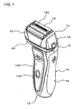
FIG. 1 is an external perspective view of one embodiment of an reciprocating electric shaver according to the present invention; -
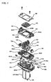
FIG. 2 is an exploded perspective view of the grip section of the shaver; -
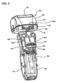
FIG. 3 is a perspective view of the internal structure of the shaver with the back casing of the grip section of the shaver removed; -
FIG. 4 is a central vertical cross-sectional side view of the shaver; -
FIG. 5 is a central vertical cross-sectional front view of the shaving unit of the shaver; -
FIG. 6 is a cross-sectional view taken along the line VI-VI inFIG. 5 ; -
FIG. 7 is an exploded perspective view of the drive mechanism of the shaver; and -
FIG. 8 is an exploded perspective view of the head part of the shaver. - In
FIGs. 1 to 3 , thereference numeral 10 is a grip section of the shaver, and this grip section is comprised of a substantially shell shapedfront casing 12 and a substantially shell shapedback casing 14 that are joined and mated at their outer edges. More specifically, the front andback casings back casings FIG. 1 shows only the right side cover 16) are fitted to hide the joining edges of the two casings, joining screws, and the like. A suitable number of engaging hooks (not illustrated) are formed integrally on the inner surfaces of thecovers 16, and these engaging holes are engaged with the front andback casings - The
reference numeral 20 is a shaving unit, and thisshaving unit 20 is comprised of ahead unit 22 and amotor 24 which are of a single unit. Thehead part 22 includesouter cutters 76,inner cutters 54, and adrive mechanism 44 which will be described below. Themotor 24 has a vertically long substantially round pillar shape, and its rotatingshaft 26 projects out of the top surface (seeFIGs. 4 to 6 ). Themotor 24 is installed in a cylindrical-shaped motor case 28 in which the upper end is open and the lower end is closed. Ahead bottom plate 30 is fixed to the upper end opening of themotor case 28 with a seal member in between. The rotatingshaft 26 projects out of thehead bottom plate 30, and a seal member is provided between these elements. Thus, themotor 24 is provided water-tightly by themotor case 28 and thehead bottom plate 30. Amotor lead line 32 is extended from the bottom surface of themotor case 28. Themotor 24 is a single unit including themotor case 28 and thehead bottom plate 30; accordingly, the "motor 24" is sometimes meant to include all of these elements in the description below. - The
head bottom plate 30 has a laterally long, substantially cup shape form; and the inside of thehead bottom plate 30 is provided with erected left and right pair of supportingarms 34. As shown inFIG. 7 , these supportingarms 34 are leaf springs which have elasticity in the lateral direction (perpendicular to the thickness), and they are urged in the lateral direction outwardly so as to tightly come into contact withtower portions 62 formed in apivot case 36 that is described below. - The
pivot case 36 is, as best seen fromFIG. 7 , comprised of a pivot casebottom plate 40, of which center portion is open in the vertical direction, and a pivot caseupper plate 42, which is provided on thebottom plate 40 so as to make a single unit, and thedrive mechanism 44 is held between these two elements. Thedrive mechanism 44 has twooscillators bottom plate 40 and theupper plate 42. Theoscillators cam shaft 26A fixed to therotating shaft 26 of themotor 24, so that theoscillators motor 24. On the top surface of theoscillators inner cutter holders inner cutter holders inner cutter holders inner cutters 54 are of a semi-cylindrical shape, and the otherinner cutter 54A (seeFIG. 6 ) is of an inverted L-shape to make a trimmer for stray beard hairs and is incorporated in theouter cutter 76 that will be described below. - A
seal pressing plate 58 is attached to the top surface of the pivot caseupper plate 42 with aseal member 56 in between. Theseal member 56 makes a liquid tight seal between the opening of thepivot case 36 and theoscillators - A left/right pair of elongated slots 60 (60A and 60B) are formed in the pivot case 36 (or in the pivot case
bottom plate 40 of the pivot case 36) which are long in a front and back direction, and the supportingarms 34 provided on thehead bottom plate 30 passes through theseslots tower portions 62 are formed on the pivot caseupper plate 42 so as to erect along the edges, in left/right direction outwardly, of the elongated slots 60. With the supportingarms 34 of thehead bottom plate 30 brought to enter into the elongated slots 60 (60A and 60B) of thepivot case 36 from below, thepivot case 36 is mounted on thehead bottom plate 30. As seen fromFIG. 7 , twopins 64 are inserted from the inner side intopin holes 34A formed in the supportingarms 34 and further intopin holes 62A formed in thetower portions 62, and awasher 66 and anE ring 68 that prevent thepins 64 from falling out are attached to the tip ends of the pins 64 (the tip ends being on the outside of the pin holes 62A of the pivot case 36). As a result, thepivot case 36 can be moved (pivoted) front and back with thepins 64 as the pivot center as shown by arrow P1 inFIG. 4 . In other words, thepins 64 are the front/back pivot center of thehead part 22. - On each one of the supporting
arm 34, awire spring 70 is, at a top portion thereof, fixed so as to be below thepin hole 34A, and both ends (leg portions) of thewire spring 70 extend downward. More specifically, thewire spring 70 is bent into a substantially inverted V-shape, both ends (leg portions) of the wire are inserted from the inside into the small holes formed, as a front and back pair, in the supportingarm 34 and extended out of the holds, and these ends (leg portions) are bent downward. Thewire spring 70 is made of a spring steel, and thus it is formed in advance to a designated shape (inverted V-shape) and provided on the supportingarm 34 by being inserted into the small holes. The bottom ends of thewire spring 70 are latched to thepivot case 36. In other words, the bottom ends of the leg portions of each one of the wire springs 70 are engaged withstep portion 62B (FIG. 7 ) formed on the inner surface of each one of thetower portions 62 of the pivot caseupper plate 42. With this structure, when the front/back pivot motion of thepivot case 36 is made, the bottom end of one of leg portions of the wire springs 70 is compressed by thestep portion 62B, and a force that returns thepivot case 36 to its center (vertical) position is generated. - In
FIG. 8 , thereference numeral 72 is an outer cutter case, and 74 is an outer cutter cover. On theouter cutter case 72, four outer cutters are provided so as to be moveable up and down. Of these outer cutters, threeouter cutters 76 are of a normal semi-cylindrical shape, and the remaining onecutter 76A is a trimmer cutter for cutting stray beard hairs. Theouter cutter 76A and the adjacent threeouter cutters 76 are urged upward by coil springs mounted in theouter cutter case 72. - The
outer cutter case 72 is provided together with theouter cutter cover 74 on thepivot case 36 to which theinner cutters 54 are provided. Theouter cutter cover 74 is locked bylock buttons 78 provided on the left and right surfaces of thepivot case 36. When thebuttons 78 are depressed to unlock, theouter cutter cover 74 is removed. - Next, a structure in which the
shaving unit 20 is pivot-supported in thegrip section 10 of the shaver will be described. On the top portion of the motor 24 (or of the motor case 28) of theshaving unit 20, projectingparts 80 projecting from the front/back surfaces are formed. These projectingparts 80 are the pivot parts that support theshaving unit 20 to pivot in a left and right directions (sideways). The projectingparts 80 are covered by anti-vibration rubbers 82 (FIG. 4 ). On the inner surface of thefront casing 12 of thegrip section 10, a concave portion is formed so that the projectingpart 80 formed on the front surface of the motor 24 (or of the motor case 28) and theanti-vibration rubber 82 are engaged therewith. - The
reference numeral 84 is a motor holder. As seen fromFIG. 2 , themotor holder 84 is mounted on the back surface of the motor 24 (or of the motor case 28), and its top portion covers the projecting part (pivot part) 80 of the back surface of the motor 24 (or of the motor case 28). A concave portion with which the projectingpart 80 on the motor 24 (motor case 28) back surface and theanti-vibration rubber 82 are engaged is provided in themotor holder 84. As shown inFIG. 2 , thismotor holder 84 straddles the top portion of themotor 24 and is temporarily held by thefront casing 12 of thegrip section 10 of the shaver. In other words,boss portions 86 into which screws for fixing theback casing 24 to thefront casing 12 are formed on thefront casing 12, and semi-cylindrical shapedconcave portions 88 with which theboss portions 86 of thefront casing 12 are engaged are formed on themotor holder 84. - Accordingly, while making a positioning-mating of the front projecting
part 80 of the motor 24 (motor case 28) with the concave portion of thefront casing 12 and making a positioning-mating of theback projecting part 80 of the motor 24 (motor case 28) with the concave portion of themotor holder 84, the semi-cylindrical shapedconcave portions 88 of themotor holder 84 are engaged with theboss portions 86 of thefront casing 12, thus temporarily holding themotor holder 84 on thefront casing 12. - On the back surface of the
motor case 28 is formed a projectingpiece 90 so as to be below the projectingpart 80 which is the pivot part. On the other hand, a substantially horizontal elongatedwindow 92 into which the projectingpiece 90 enters is formed in themotor holder 84. Thus, with themotor holder 84 being mounted on the motor 24 (or on the motor case 28), twocoil springs 94 are compression-mounted inside theelongated window 92 so that thesesprings 94 sandwich the projectingpiece 90 from both the left and right sides. These coil springs 94, while making it possible for theshaving unit 20 to pivot left and right as shown by arrow P2 inFIG. 5 , impart a force that returns the shavingunit 20 to its erect (vertical) position (center position). - In
FIGs. 3 and4 , thereference numeral 96 is an inner cover, and this is attached to the bottom portion of thefront casing 12. Apower supply unit 104 that includes a battery 98 (FIG. 4 ), awiring substrate 100, awarning display light 102 and the like is housed in a watertight fashion between thisinner cover 96 and thefront casing 12. As is clear fromFIGs. 1 and4 , adecorative plate 106 is attached to the front surface of thefront casing 12. Apower switch 108 is attached to thisdecorative plate 106. A translucent coating is applied on the part that covers thewarning display light 102 at the bottom portion of thisdecorative plate 106, so that the charge warning display of thewarning display light 102 is visible from the outside. - After attaching the
inner cover 96 which waterproofs thepower supply unit 104, themotor lead line 32 of themotor 24 is connected to thepower supply unit 104 with sufficient length allowed. Then, theback casing 14 is mated to thefront casing 12 and then fixed thereto using six screws. When the front and back casings are fixed together, themotor holder 84 is fixed by the screws that are used for fixing theback casing 14 to thefront casing 12. - On this
back casing 14 is provided anedge trimming cutter 110 so that it can flip up and down. As seen fromFIG. 4 , thisedge trimming cutter 110 opens, as indicated by a curved tow-headed arrow, to the outside about its top portion when theoperating element 112 that moves up and down is slid in the upward direction as indicated by a straight arrow. When theedge trimming cutter 110 opens, avibration cutter 110A (FIG. 4 ) of theedge trimming cutter 110 is engaged with a drive lever 114 (seeFIGs. 4 and6 ). More specifically, thedrive lever 114 is held by asupport pin 116 which is perpendicular to thehead bottom plate 30 at the back of therotation shaft 26 of themotor 24, and that front end (one end of the rotation shaft 26) is engaged with the cam of the crank shapedcam shaft 26A, and the back end faces anotch 118 provided at the back edge of thehead bottom plate 30. Aconcave portion 114A that opens upward and downward is formed on the back end of thedrive lever 114; and when theedge trimming cutter 110 is opened, a sphere shaped engagingpart 110B provided at the top edge (FIG. 4 ) of thevibration cutter 110A engages with thisconcave portion 114A. - Accordingly, when
motor 24 is activated, thedrive lever 114 is vibrated about thesupport pin 116, and thus thevibration cutter 110A of theedge trimming cutter 110 makes reciprocating vibrations. If theedge trimming cutter 110 is housed back, theengaging part 110B of thevibration cutter 110A is brought out of theconcave portion 114A of thedrive lever 114, and thevibration cutter 110A is stopped. - As seen from the above, in the present invention, the
motor 24 of theshaving unit 20 is inserted from above into thegrip section 10 of the shaver, and in a state that theshaving unit 20 is pivot-supported by thefront casing 12 and themotor holder 84, theback casing 14 is fixed to thefront casing 12. The covers 16 (FIG. 1 ) are then fitted to the left and right side surfaces of thegrip section 10. - If the electric shaver of the present invention as described above is moved to the left and right while the
outer cutters 76 being pressed against the skin during shaving, theshaving unit 20 pivots to the left and right using the projectingparts 80, which are the pivot part, as the pivot center. In addition, if the shaver is moved up and down and front and back, thehead part 22 is pivoted up and down and front and back. Accordingly, theouter cutters 76 can be moved while making close contact with the skin, and a smooth shaving can be performed. In the present invention, the return force with respect to the left and right direction pivot motion and the return force with respect to the front and back and up and down direction pivot motion can be set independently from each other by the separate, different springs, that is, by the coil springs 94 and by the wire springs 70; accordingly, the freedom for setting the return force of the head part is increased.
Claims (3)
- Reciprocating electric shaver including a shaving unit (20) in which a substantially semi-cylindrical, horizontal outer cutter (76), an inner cutter (54) that makes sliding contact with an inner surface of the outer cutter (76), and a drive mechanism (44) that reciprocates the inner cutter (54) are formed into a single unit, with said shaving unit (20) being pivotable left and right, wherein:said shaving unit (20) is supported in a grip section (10) of said shaver by a front/back pair of pivot parts (80) that sandwich said shaving unit (20) from a front and back thereof, anda head part (22) that includes said outer cutter (76) and inner cutter (54) and said drive mechanism (44) is provided so as to pivot front and back with respect to said grip section (10),characterized in
that also a motor (24) is formed into said single unit and said drive mechanism (44) reciprocates the inner cutter (54) using said motor (24),
that said front/back pair of pivot parts (80) sandwich also said motor (24) from a front end and back end thereof,
that said drive mechanism (44) is provided so as to pivot front and back with respect to said motor (24),
that said grip section (10) comprises a front casing (12), a back casing (14), and a motor holder (84) which is inside the back casing (14) and held by the front casing (12), and
that said pivot parts (80) that support the motor (24) are positioned respectively between the motor (24) and the front casing (12) and between the motor (24) and the motor holder (84). - Reciprocating electric shaver according to claim 1, wherein
said motor holder (84) is formed with a horizontal elongated window (92) below the pivot part (80),
said motor (24) is provided on a back surface thereof with a projecting piece (90) that enters said elongated window (92) so as to be moveable left and right, and
coil springs (94) are provided in said elongated window (92) so as to sandwich said projecting piece (90) from both left and right sides of the projecting piece (90) and so as to return the shaving unit (20) to a return position thereof in a left/right direction. - Reciprocating electric shaver according to claim 1, wherein
said head part (22) includes a pivot case (36) that pivots front and back with respect to the motor (2A),
said drive mechanism (44) is provided in said pivot case (36), and
said pivot case (36) holds therein an outer cutter case (72), which holds the outer cutter (76) so as to be moveable up and down, and an inner cutter holder (50, 52), which holds, while urging upward, the inner cutter (54).
Applications Claiming Priority (1)
| Application Number | Priority Date | Filing Date | Title |
|---|---|---|---|
| JP2009104740A JP5388188B2 (en) | 2009-04-23 | 2009-04-23 | Reciprocating electric razor |
Publications (3)
| Publication Number | Publication Date |
|---|---|
| EP2243604A2 EP2243604A2 (en) | 2010-10-27 |
| EP2243604A3 EP2243604A3 (en) | 2010-12-22 |
| EP2243604B1 true EP2243604B1 (en) | 2012-03-28 |
Family
ID=42313003
Family Applications (1)
| Application Number | Title | Priority Date | Filing Date |
|---|---|---|---|
| EP10004266A Not-in-force EP2243604B1 (en) | 2009-04-23 | 2010-04-22 | Reciprocating electric shaver |
Country Status (10)
| Country | Link |
|---|---|
| US (1) | US8720069B2 (en) |
| EP (1) | EP2243604B1 (en) |
| JP (1) | JP5388188B2 (en) |
| KR (1) | KR20100117037A (en) |
| CN (1) | CN101870114B (en) |
| AT (1) | ATE551161T1 (en) |
| CA (1) | CA2701382A1 (en) |
| HK (1) | HK1150037A1 (en) |
| MX (1) | MX2010004444A (en) |
| TW (1) | TW201043421A (en) |
Families Citing this family (19)
| Publication number | Priority date | Publication date | Assignee | Title |
|---|---|---|---|---|
| JP4595967B2 (en) * | 2007-07-12 | 2010-12-08 | パナソニック電工株式会社 | Reciprocating electric razor blade |
| JP2009201714A (en) * | 2008-02-28 | 2009-09-10 | Sanyo Electric Co Ltd | Electric shaver |
| JP5453188B2 (en) * | 2010-07-08 | 2014-03-26 | パナソニック株式会社 | Reciprocating electric razor |
| JP2012016495A (en) * | 2010-07-08 | 2012-01-26 | Panasonic Electric Works Co Ltd | Reciprocating electric shaver |
| JP2012016492A (en) * | 2010-07-08 | 2012-01-26 | Panasonic Electric Works Co Ltd | Reciprocating electric shaver |
| USD753342S1 (en) * | 2014-12-18 | 2016-04-05 | Panasonic Intellectual Property Management Co., Ltd. | Electric shaver |
| USD752811S1 (en) * | 2015-03-20 | 2016-03-29 | Panasonic Intellectual Property Management Co., Ltd. | Electric shaver |
| USD758018S1 (en) * | 2015-03-20 | 2016-05-31 | Panasonic Intellectual Property Management Co., Ltd. | Shaver head |
| JP6715506B2 (en) | 2016-02-09 | 2020-07-01 | パナソニックIpマネジメント株式会社 | Electric razor |
| US10045795B2 (en) * | 2016-04-07 | 2018-08-14 | Soft Lines International, Ltd. | Handheld cosmetic device with pivoting head |
| EP3300844B1 (en) * | 2016-09-28 | 2020-04-15 | Braun GmbH | Electric shaver |
| EP3300845B1 (en) * | 2016-09-28 | 2019-10-23 | Braun GmbH | Shaver coupling and electrical shaver with coupling |
| EP3300861B1 (en) | 2016-09-28 | 2019-07-03 | Braun GmbH | Electrically driven device |
| EP3300850B1 (en) * | 2016-09-28 | 2019-10-23 | Braun GmbH | Electrically-driven razor |
| JP6854695B2 (en) * | 2017-05-02 | 2021-04-07 | マクセルイズミ株式会社 | Reciprocating electric razor |
| EP3403778B1 (en) * | 2017-05-17 | 2020-01-01 | Panasonic Intellectual Property Management Co., Ltd. | Hair cutting device |
| CN106963460B (en) * | 2017-05-23 | 2023-07-21 | 深圳价之链跨境电商有限公司 | Skin cleaning device and application method thereof |
| CN108258874B (en) * | 2017-12-27 | 2019-11-01 | 广州赤力科技有限公司 | Rotary actuator and electric device |
| US20230064384A1 (en) * | 2021-08-27 | 2023-03-02 | Wahl Clipper Corporation | Shaver |
Family Cites Families (30)
| Publication number | Priority date | Publication date | Assignee | Title |
|---|---|---|---|---|
| DE3822332A1 (en) * | 1988-07-01 | 1990-01-04 | Philips Patentverwaltung | HOUSEHOLD VIBRATION DEVICE |
| US5611145A (en) * | 1991-12-20 | 1997-03-18 | Wetzel; Matthias | Dry-shaving apparatus |
| GB2266070A (en) | 1992-04-10 | 1993-10-20 | Gillette Co | Dry shaver |
| AT398720B (en) * | 1992-07-24 | 1995-01-25 | Koninkl Philips Electronics Nv | SHAVER WITH A SHEAR HEAD FRAME AND A FILM FRAME SUSPENDED ON THIS |
| DE4303972C1 (en) * | 1993-02-11 | 1993-10-14 | Braun Ag | Electric dry razor with pivoted cutting head - has cutting head frame supported by pivot screws fitting in metal bearing elements in opposing carrier arms |
| JPH06335575A (en) | 1993-05-28 | 1994-12-06 | Tokyo Electric Co Ltd | Shaver |
| JPH06343776A (en) * | 1993-06-10 | 1994-12-20 | Tokyo Electric Co Ltd | Electric shaver |
| GB2290739B (en) * | 1994-06-29 | 1998-01-21 | Sanyo Electric Co | Electric shaver |
| US5953825A (en) * | 1996-01-16 | 1999-09-21 | The Gillette Company | Safety razors |
| KR100415352B1 (en) * | 1996-05-29 | 2004-06-30 | 산요덴키가부시키가이샤 | Electric Shaver |
| JPH1043443A (en) | 1996-08-07 | 1998-02-17 | Tec Corp | Electric razor |
| DE19736776C2 (en) * | 1997-08-23 | 1999-06-02 | Braun Gmbh | Dry shaver |
| DE19859622A1 (en) * | 1998-12-23 | 2000-07-06 | Braun Gmbh | Drive device for oscillating electrical products for personal use, in particular dry shavers |
| EP1162721B1 (en) * | 2000-06-07 | 2005-12-21 | Matsushita Electric Works, Ltd. | Linear oscillating actuator |
| DE10052127A1 (en) * | 2000-10-20 | 2002-05-29 | Braun Gmbh | Electrically operated hair removal device |
| JP3945376B2 (en) | 2001-11-15 | 2007-07-18 | 松下電工株式会社 | Electric razor |
| KR100563481B1 (en) * | 2002-06-17 | 2006-03-27 | 마츠시다 덴코 가부시키가이샤 | Electric Shaver Floating Head Support Structure |
| DE102004028064A1 (en) * | 2004-06-09 | 2006-01-05 | Braun Gmbh | Electric shaver with a swiveling shaving head |
| JP4148199B2 (en) * | 2004-07-30 | 2008-09-10 | 松下電工株式会社 | Electric razor |
| GB2419102A (en) * | 2004-10-18 | 2006-04-19 | Gillette Man Inc | Powered safety razor systems |
| JP4552646B2 (en) * | 2004-12-16 | 2010-09-29 | パナソニック電工株式会社 | Hair removal equipment |
| JP4604846B2 (en) * | 2005-05-31 | 2011-01-05 | パナソニック電工株式会社 | Hair treatment equipment |
| JP4229091B2 (en) * | 2005-05-31 | 2009-02-25 | パナソニック電工株式会社 | Hair treatment equipment |
| JP4715425B2 (en) * | 2005-09-27 | 2011-07-06 | パナソニック電工株式会社 | Electric razor |
| JP3813979B2 (en) * | 2005-12-06 | 2006-08-23 | 九州日立マクセル株式会社 | Electric razor |
| DE102006034050A1 (en) * | 2006-07-20 | 2008-01-24 | Braun Gmbh | Electric shaver |
| JP4969947B2 (en) * | 2006-08-11 | 2012-07-04 | 株式会社泉精器製作所 | Reciprocating electric razor |
| US8141253B2 (en) * | 2007-08-31 | 2012-03-27 | The Gillette Company | Personal care assembly |
| DE102008031132A1 (en) * | 2008-07-01 | 2010-01-07 | Braun Gmbh | Small electrical appliance for removing hair |
| JP5396342B2 (en) * | 2010-07-08 | 2014-01-22 | パナソニック株式会社 | Reciprocating electric razor |
-
2009
- 2009-04-23 JP JP2009104740A patent/JP5388188B2/en active Active
-
2010
- 2010-04-22 AT AT10004266T patent/ATE551161T1/en active
- 2010-04-22 CN CN2010101558178A patent/CN101870114B/en active Active
- 2010-04-22 EP EP10004266A patent/EP2243604B1/en not_active Not-in-force
- 2010-04-22 KR KR1020100037356A patent/KR20100117037A/en active IP Right Grant
- 2010-04-22 US US12/799,303 patent/US8720069B2/en active Active
- 2010-04-22 CA CA2701382A patent/CA2701382A1/en not_active Abandoned
- 2010-04-23 TW TW099112846A patent/TW201043421A/en unknown
- 2010-04-23 MX MX2010004444A patent/MX2010004444A/en not_active Application Discontinuation
-
2011
- 2011-04-26 HK HK11104162.1A patent/HK1150037A1/en not_active IP Right Cessation
Also Published As
| Publication number | Publication date |
|---|---|
| EP2243604A3 (en) | 2010-12-22 |
| CA2701382A1 (en) | 2010-10-23 |
| TW201043421A (en) | 2010-12-16 |
| MX2010004444A (en) | 2010-10-22 |
| CN101870114B (en) | 2012-05-23 |
| HK1150037A1 (en) | 2011-10-28 |
| JP5388188B2 (en) | 2014-01-15 |
| CN101870114A (en) | 2010-10-27 |
| US20100269350A1 (en) | 2010-10-28 |
| JP2010252941A (en) | 2010-11-11 |
| KR20100117037A (en) | 2010-11-02 |
| US8720069B2 (en) | 2014-05-13 |
| ATE551161T1 (en) | 2012-04-15 |
| EP2243604A2 (en) | 2010-10-27 |
Similar Documents
| Publication | Publication Date | Title |
|---|---|---|
| EP2243604B1 (en) | Reciprocating electric shaver | |
| KR100768992B1 (en) | Hair cutting device | |
| US7536787B2 (en) | Wet razor and electric trimmer assembly | |
| JP6468644B2 (en) | Electric razor | |
| US6931731B2 (en) | Electric shaver | |
| EP2148765A1 (en) | Shaver | |
| JP3574440B2 (en) | Electric razor | |
| KR200412311Y1 (en) | Head Tilting Apparatus for Slim Shape Electric Shaver | |
| US20040055158A1 (en) | Electric shaver | |
| JP3826876B2 (en) | Electric razor | |
| JPS6139071B2 (en) | ||
| JPH05146562A (en) | Reciprocating electric razor | |
| JP2696361B2 (en) | Rotary electric razor | |
| JP3945376B2 (en) | Electric razor | |
| JPH05253362A (en) | Reciprocating electric shaver | |
| JP2519930B2 (en) | Electric razor | |
| JPH04220282A (en) | Reciprocating type electric razor | |
| JP3786720B2 (en) | Rotary electric razor | |
| JP2004016812A (en) | Movable head supporting structure for electric razor | |
| JPH09140955A (en) | Rotary electric razor | |
| JPH04348786A (en) | Reciprocating type electric razor | |
| JPS6216663B2 (en) | ||
| JPH02215488A (en) | Trimmer device for electric razor |
Legal Events
| Date | Code | Title | Description |
|---|---|---|---|
| PUAI | Public reference made under article 153(3) epc to a published international application that has entered the european phase |
Free format text: ORIGINAL CODE: 0009012 |
|
| AK | Designated contracting states |
Kind code of ref document: A2 Designated state(s): AT BE BG CH CY CZ DE DK EE ES FI FR GB GR HR HU IE IS IT LI LT LU LV MC MK MT NL NO PL PT RO SE SI SK SM TR |
|
| AX | Request for extension of the european patent |
Extension state: AL BA ME RS |
|
| PUAL | Search report despatched |
Free format text: ORIGINAL CODE: 0009013 |
|
| AK | Designated contracting states |
Kind code of ref document: A3 Designated state(s): AT BE BG CH CY CZ DE DK EE ES FI FR GB GR HR HU IE IS IT LI LT LU LV MC MK MT NL NO PL PT RO SE SI SK SM TR |
|
| AX | Request for extension of the european patent |
Extension state: AL BA ME RS |
|
| 17P | Request for examination filed |
Effective date: 20110622 |
|
| GRAP | Despatch of communication of intention to grant a patent |
Free format text: ORIGINAL CODE: EPIDOSNIGR1 |
|
| GRAS | Grant fee paid |
Free format text: ORIGINAL CODE: EPIDOSNIGR3 |
|
| GRAA | (expected) grant |
Free format text: ORIGINAL CODE: 0009210 |
|
| AK | Designated contracting states |
Kind code of ref document: B1 Designated state(s): AT BE BG CH CY CZ DE DK EE ES FI FR GB GR HR HU IE IS IT LI LT LU LV MC MK MT NL NO PL PT RO SE SI SK SM TR |
|
| REG | Reference to a national code |
Ref country code: GB Ref legal event code: FG4D |
|
| REG | Reference to a national code |
Ref country code: CH Ref legal event code: EP |
|
| REG | Reference to a national code |
Ref country code: AT Ref legal event code: REF Ref document number: 551161 Country of ref document: AT Kind code of ref document: T Effective date: 20120415 |
|
| REG | Reference to a national code |
Ref country code: IE Ref legal event code: FG4D |
|
| REG | Reference to a national code |
Ref country code: DE Ref legal event code: R096 Ref document number: 602010001157 Country of ref document: DE Effective date: 20120524 |
|
| REG | Reference to a national code |
Ref country code: NL Ref legal event code: T3 |
|
| PG25 | Lapsed in a contracting state [announced via postgrant information from national office to epo] |
Ref country code: HR Free format text: LAPSE BECAUSE OF FAILURE TO SUBMIT A TRANSLATION OF THE DESCRIPTION OR TO PAY THE FEE WITHIN THE PRESCRIBED TIME-LIMIT Effective date: 20120328 Ref country code: NO Free format text: LAPSE BECAUSE OF FAILURE TO SUBMIT A TRANSLATION OF THE DESCRIPTION OR TO PAY THE FEE WITHIN THE PRESCRIBED TIME-LIMIT Effective date: 20120628 Ref country code: LT Free format text: LAPSE BECAUSE OF FAILURE TO SUBMIT A TRANSLATION OF THE DESCRIPTION OR TO PAY THE FEE WITHIN THE PRESCRIBED TIME-LIMIT Effective date: 20120328 |
|
| LTIE | Lt: invalidation of european patent or patent extension |
Effective date: 20120328 |
|
| PG25 | Lapsed in a contracting state [announced via postgrant information from national office to epo] |
Ref country code: FI Free format text: LAPSE BECAUSE OF FAILURE TO SUBMIT A TRANSLATION OF THE DESCRIPTION OR TO PAY THE FEE WITHIN THE PRESCRIBED TIME-LIMIT Effective date: 20120328 Ref country code: LV Free format text: LAPSE BECAUSE OF FAILURE TO SUBMIT A TRANSLATION OF THE DESCRIPTION OR TO PAY THE FEE WITHIN THE PRESCRIBED TIME-LIMIT Effective date: 20120328 Ref country code: GR Free format text: LAPSE BECAUSE OF FAILURE TO SUBMIT A TRANSLATION OF THE DESCRIPTION OR TO PAY THE FEE WITHIN THE PRESCRIBED TIME-LIMIT Effective date: 20120629 |
|
| REG | Reference to a national code |
Ref country code: AT Ref legal event code: MK05 Ref document number: 551161 Country of ref document: AT Kind code of ref document: T Effective date: 20120328 |
|
| PG25 | Lapsed in a contracting state [announced via postgrant information from national office to epo] |
Ref country code: CY Free format text: LAPSE BECAUSE OF FAILURE TO SUBMIT A TRANSLATION OF THE DESCRIPTION OR TO PAY THE FEE WITHIN THE PRESCRIBED TIME-LIMIT Effective date: 20120328 |
|
| PG25 | Lapsed in a contracting state [announced via postgrant information from national office to epo] |
Ref country code: RO Free format text: LAPSE BECAUSE OF FAILURE TO SUBMIT A TRANSLATION OF THE DESCRIPTION OR TO PAY THE FEE WITHIN THE PRESCRIBED TIME-LIMIT Effective date: 20120328 Ref country code: IS Free format text: LAPSE BECAUSE OF FAILURE TO SUBMIT A TRANSLATION OF THE DESCRIPTION OR TO PAY THE FEE WITHIN THE PRESCRIBED TIME-LIMIT Effective date: 20120728 Ref country code: SE Free format text: LAPSE BECAUSE OF FAILURE TO SUBMIT A TRANSLATION OF THE DESCRIPTION OR TO PAY THE FEE WITHIN THE PRESCRIBED TIME-LIMIT Effective date: 20120328 Ref country code: EE Free format text: LAPSE BECAUSE OF FAILURE TO SUBMIT A TRANSLATION OF THE DESCRIPTION OR TO PAY THE FEE WITHIN THE PRESCRIBED TIME-LIMIT Effective date: 20120328 Ref country code: SI Free format text: LAPSE BECAUSE OF FAILURE TO SUBMIT A TRANSLATION OF THE DESCRIPTION OR TO PAY THE FEE WITHIN THE PRESCRIBED TIME-LIMIT Effective date: 20120328 Ref country code: PL Free format text: LAPSE BECAUSE OF FAILURE TO SUBMIT A TRANSLATION OF THE DESCRIPTION OR TO PAY THE FEE WITHIN THE PRESCRIBED TIME-LIMIT Effective date: 20120328 Ref country code: BE Free format text: LAPSE BECAUSE OF FAILURE TO SUBMIT A TRANSLATION OF THE DESCRIPTION OR TO PAY THE FEE WITHIN THE PRESCRIBED TIME-LIMIT Effective date: 20120328 Ref country code: CZ Free format text: LAPSE BECAUSE OF FAILURE TO SUBMIT A TRANSLATION OF THE DESCRIPTION OR TO PAY THE FEE WITHIN THE PRESCRIBED TIME-LIMIT Effective date: 20120328 |
|
| PG25 | Lapsed in a contracting state [announced via postgrant information from national office to epo] |
Ref country code: SK Free format text: LAPSE BECAUSE OF FAILURE TO SUBMIT A TRANSLATION OF THE DESCRIPTION OR TO PAY THE FEE WITHIN THE PRESCRIBED TIME-LIMIT Effective date: 20120328 Ref country code: PT Free format text: LAPSE BECAUSE OF FAILURE TO SUBMIT A TRANSLATION OF THE DESCRIPTION OR TO PAY THE FEE WITHIN THE PRESCRIBED TIME-LIMIT Effective date: 20120730 Ref country code: MC Free format text: LAPSE BECAUSE OF NON-PAYMENT OF DUE FEES Effective date: 20120430 |
|
| REG | Reference to a national code |
Ref country code: IE Ref legal event code: MM4A |
|
| PG25 | Lapsed in a contracting state [announced via postgrant information from national office to epo] |
Ref country code: DK Free format text: LAPSE BECAUSE OF FAILURE TO SUBMIT A TRANSLATION OF THE DESCRIPTION OR TO PAY THE FEE WITHIN THE PRESCRIBED TIME-LIMIT Effective date: 20120328 Ref country code: AT Free format text: LAPSE BECAUSE OF FAILURE TO SUBMIT A TRANSLATION OF THE DESCRIPTION OR TO PAY THE FEE WITHIN THE PRESCRIBED TIME-LIMIT Effective date: 20120328 Ref country code: IE Free format text: LAPSE BECAUSE OF NON-PAYMENT OF DUE FEES Effective date: 20120422 |
|
| PLBE | No opposition filed within time limit |
Free format text: ORIGINAL CODE: 0009261 |
|
| STAA | Information on the status of an ep patent application or granted ep patent |
Free format text: STATUS: NO OPPOSITION FILED WITHIN TIME LIMIT |
|
| PG25 | Lapsed in a contracting state [announced via postgrant information from national office to epo] |
Ref country code: MK Free format text: LAPSE BECAUSE OF FAILURE TO SUBMIT A TRANSLATION OF THE DESCRIPTION OR TO PAY THE FEE WITHIN THE PRESCRIBED TIME-LIMIT Effective date: 20120328 Ref country code: IT Free format text: LAPSE BECAUSE OF FAILURE TO SUBMIT A TRANSLATION OF THE DESCRIPTION OR TO PAY THE FEE WITHIN THE PRESCRIBED TIME-LIMIT Effective date: 20120328 |
|
| 26N | No opposition filed |
Effective date: 20130103 |
|
| REG | Reference to a national code |
Ref country code: FR Ref legal event code: ST Effective date: 20130204 |
|
| REG | Reference to a national code |
Ref country code: DE Ref legal event code: R097 Ref document number: 602010001157 Country of ref document: DE Effective date: 20130103 |
|
| PG25 | Lapsed in a contracting state [announced via postgrant information from national office to epo] |
Ref country code: FR Free format text: LAPSE BECAUSE OF NON-PAYMENT OF DUE FEES Effective date: 20120529 Ref country code: ES Free format text: LAPSE BECAUSE OF FAILURE TO SUBMIT A TRANSLATION OF THE DESCRIPTION OR TO PAY THE FEE WITHIN THE PRESCRIBED TIME-LIMIT Effective date: 20120709 |
|
| PG25 | Lapsed in a contracting state [announced via postgrant information from national office to epo] |
Ref country code: MT Free format text: LAPSE BECAUSE OF FAILURE TO SUBMIT A TRANSLATION OF THE DESCRIPTION OR TO PAY THE FEE WITHIN THE PRESCRIBED TIME-LIMIT Effective date: 20120328 Ref country code: BG Free format text: LAPSE BECAUSE OF FAILURE TO SUBMIT A TRANSLATION OF THE DESCRIPTION OR TO PAY THE FEE WITHIN THE PRESCRIBED TIME-LIMIT Effective date: 20120628 |
|
| REG | Reference to a national code |
Ref country code: NL Ref legal event code: V1 Effective date: 20131101 |
|
| PG25 | Lapsed in a contracting state [announced via postgrant information from national office to epo] |
Ref country code: NL Free format text: LAPSE BECAUSE OF NON-PAYMENT OF DUE FEES Effective date: 20131101 |
|
| PG25 | Lapsed in a contracting state [announced via postgrant information from national office to epo] |
Ref country code: TR Free format text: LAPSE BECAUSE OF FAILURE TO SUBMIT A TRANSLATION OF THE DESCRIPTION OR TO PAY THE FEE WITHIN THE PRESCRIBED TIME-LIMIT Effective date: 20120328 |
|
| PG25 | Lapsed in a contracting state [announced via postgrant information from national office to epo] |
Ref country code: LU Free format text: LAPSE BECAUSE OF NON-PAYMENT OF DUE FEES Effective date: 20120422 Ref country code: SM Free format text: LAPSE BECAUSE OF FAILURE TO SUBMIT A TRANSLATION OF THE DESCRIPTION OR TO PAY THE FEE WITHIN THE PRESCRIBED TIME-LIMIT Effective date: 20120328 |
|
| PG25 | Lapsed in a contracting state [announced via postgrant information from national office to epo] |
Ref country code: HU Free format text: LAPSE BECAUSE OF FAILURE TO SUBMIT A TRANSLATION OF THE DESCRIPTION OR TO PAY THE FEE WITHIN THE PRESCRIBED TIME-LIMIT Effective date: 20100422 |
|
| REG | Reference to a national code |
Ref country code: CH Ref legal event code: PL |
|
| PG25 | Lapsed in a contracting state [announced via postgrant information from national office to epo] |
Ref country code: CH Free format text: LAPSE BECAUSE OF NON-PAYMENT OF DUE FEES Effective date: 20140430 Ref country code: LI Free format text: LAPSE BECAUSE OF NON-PAYMENT OF DUE FEES Effective date: 20140430 |
|
| REG | Reference to a national code |
Ref country code: DE Ref legal event code: R082 Ref document number: 602010001157 Country of ref document: DE Representative=s name: PATENTANWALTSKANZLEI HINKELMANN, DE |
|
| REG | Reference to a national code |
Ref country code: DE Ref legal event code: R082 Ref document number: 602010001157 Country of ref document: DE Representative=s name: PATENTANWALTSKANZLEI HINKELMANN, DE |
|
| PGFP | Annual fee paid to national office [announced via postgrant information from national office to epo] |
Ref country code: DE Payment date: 20190418 Year of fee payment: 10 |
|
| PGFP | Annual fee paid to national office [announced via postgrant information from national office to epo] |
Ref country code: GB Payment date: 20190418 Year of fee payment: 10 |
|
| REG | Reference to a national code |
Ref country code: DE Ref legal event code: R119 Ref document number: 602010001157 Country of ref document: DE |
|
| PG25 | Lapsed in a contracting state [announced via postgrant information from national office to epo] |
Ref country code: DE Free format text: LAPSE BECAUSE OF NON-PAYMENT OF DUE FEES Effective date: 20201103 |
|
| GBPC | Gb: european patent ceased through non-payment of renewal fee |
Effective date: 20200422 |
|
| PG25 | Lapsed in a contracting state [announced via postgrant information from national office to epo] |
Ref country code: GB Free format text: LAPSE BECAUSE OF NON-PAYMENT OF DUE FEES Effective date: 20200422 |