EP2243452A1 - Movable supporting device - Google Patents
Movable supporting device Download PDFInfo
- Publication number
- EP2243452A1 EP2243452A1 EP09158285A EP09158285A EP2243452A1 EP 2243452 A1 EP2243452 A1 EP 2243452A1 EP 09158285 A EP09158285 A EP 09158285A EP 09158285 A EP09158285 A EP 09158285A EP 2243452 A1 EP2243452 A1 EP 2243452A1
- Authority
- EP
- European Patent Office
- Prior art keywords
- supporting device
- movable supporting
- control assembly
- operable
- releasable lock
- Prior art date
- Legal status (The legal status is an assumption and is not a legal conclusion. Google has not performed a legal analysis and makes no representation as to the accuracy of the status listed.)
- Withdrawn
Links
- 230000003387 muscular Effects 0.000 description 4
- 230000000712 assembly Effects 0.000 description 3
- 238000000429 assembly Methods 0.000 description 3
- 238000010276 construction Methods 0.000 description 2
- 239000004952 Polyamide Substances 0.000 description 1
- 230000003213 activating effect Effects 0.000 description 1
- XAGFODPZIPBFFR-UHFFFAOYSA-N aluminium Chemical compound [Al] XAGFODPZIPBFFR-UHFFFAOYSA-N 0.000 description 1
- 229910052782 aluminium Inorganic materials 0.000 description 1
- 230000000694 effects Effects 0.000 description 1
- 239000000463 material Substances 0.000 description 1
- 229920002647 polyamide Polymers 0.000 description 1
Images


Classifications
-
- A—HUMAN NECESSITIES
- A61—MEDICAL OR VETERINARY SCIENCE; HYGIENE
- A61G—TRANSPORT, PERSONAL CONVEYANCES, OR ACCOMMODATION SPECIALLY ADAPTED FOR PATIENTS OR DISABLED PERSONS; OPERATING TABLES OR CHAIRS; CHAIRS FOR DENTISTRY; FUNERAL DEVICES
- A61G5/00—Chairs or personal conveyances specially adapted for patients or disabled persons, e.g. wheelchairs
- A61G5/10—Parts, details or accessories
-
- A—HUMAN NECESSITIES
- A61—MEDICAL OR VETERINARY SCIENCE; HYGIENE
- A61G—TRANSPORT, PERSONAL CONVEYANCES, OR ACCOMMODATION SPECIALLY ADAPTED FOR PATIENTS OR DISABLED PERSONS; OPERATING TABLES OR CHAIRS; CHAIRS FOR DENTISTRY; FUNERAL DEVICES
- A61G5/00—Chairs or personal conveyances specially adapted for patients or disabled persons, e.g. wheelchairs
- A61G5/10—Parts, details or accessories
- A61G5/1054—Large wheels, e.g. higher than the seat portion
-
- A—HUMAN NECESSITIES
- A61—MEDICAL OR VETERINARY SCIENCE; HYGIENE
- A61G—TRANSPORT, PERSONAL CONVEYANCES, OR ACCOMMODATION SPECIALLY ADAPTED FOR PATIENTS OR DISABLED PERSONS; OPERATING TABLES OR CHAIRS; CHAIRS FOR DENTISTRY; FUNERAL DEVICES
- A61G2203/00—General characteristics of devices
- A61G2203/10—General characteristics of devices characterised by specific control means, e.g. for adjustment or steering
- A61G2203/14—Joysticks
-
- A—HUMAN NECESSITIES
- A61—MEDICAL OR VETERINARY SCIENCE; HYGIENE
- A61G—TRANSPORT, PERSONAL CONVEYANCES, OR ACCOMMODATION SPECIALLY ADAPTED FOR PATIENTS OR DISABLED PERSONS; OPERATING TABLES OR CHAIRS; CHAIRS FOR DENTISTRY; FUNERAL DEVICES
- A61G5/00—Chairs or personal conveyances specially adapted for patients or disabled persons, e.g. wheelchairs
- A61G5/04—Chairs or personal conveyances specially adapted for patients or disabled persons, e.g. wheelchairs motor-driven
Definitions
- the present invention relates generally to support devices for control assemblies.
- a control assembly in connection with a seat is most often mounted somewhere along the side of the seat, enabling the person to use the control assembly with one of the hands while seated in the seat.
- Having the control assembly being supported by a movable support device enables the control assembly to be adjusted such that the control assembly is placed in a desired position by the particular user of the seat.
- the desired position is typically in front of the person on the right or left hand side, whereas when not using the control assembly, the desired position is typically in a retracted position further back or even behind the user.
- a movable support device for controlling the position of a control assembly is disclosed. The movable support device of US5326063 allows the control assembly to be locked in a retracted and an extended position.
- An electrically powered wheelchair is usually controlled by a control assembly, such as a joystick, a touch panel or a finger control assembly.
- a control assembly such as a joystick, a touch panel or a finger control assembly.
- the electrically powered wheelchair is used as means of transportation as well as means for sitting when working, eating and interacting with other persons.
- control precision and comfort is of essence, why it is important that the control assembly can be positioned where the user desires.
- the electrically powered wheelchair is used as sitting means, especially at a table, it is highly desirable that the control assembly can be stowed away, not to interfere with the mobility or activities of the user.
- a user of an electrically powered wheelchair usually have some sort of disability limiting the person's ability to move or limiting the muscular strength of that person. This makes it difficult for the person to move objects or to affect mechanical constructions with muscular strength. For non-disabled users it may be difficult to move a heavy control assembly with the precision required to position the control assembly in a desired position if the movable supporting device, to which the control assembly is mounted, should fixate the control assembly adequately in normal use.
- a movable supporting device for changing the position of a control assembly comprises an operable joint and an electrically releasable lock.
- the operable joint is adapted to be locked by the electrically releasable lock such that the control assembly can be locked in a position along the motion track of the movable supporting member.
- the electrically releasable lock comprises an electromagnet which interacts with friction creating elements for locking the movable supporting device, such as an electromagnetic break.
- the operable joint of the movable supporting device is actively operable, e.g. by means of an electric motor.
- the movable supporting device further comprises a second operable joint, which may be interlinked with said first operable joint.
- the two operable joints could be interlinked using a timing belt.
- the movable supporting device could be adapted to create a pantographic movement of the control assembly, for always maintaining the orientation of the control assembly.
- the control assembly could be a mechanical, hydraulic, pneumatic or electric and could be in the form of for example a joystick, a leaver, a wheel, a knob or a touch panel.
- the movable supporting device could further comprise a switch for controlling the electrically releasable lock, which could be an electrical switch possible to operate without the use of large muscular force, which for example could be placed in connection with the control assembly for easy access by a user.
- a switch for controlling the electrically releasable lock which could be an electrical switch possible to operate without the use of large muscular force, which for example could be placed in connection with the control assembly for easy access by a user.
- the movable supporting device is movable along a motion track
- the electrically releasable lock is adapted to lock the movable supporting device anywhere along the motion track.
- the movable supporting device further comprises a fixating element, which for example could be adapted to fixate the movable supporting device to an armrest.
- An operable joint is to be understood as a joint connecting two or more parts in a way such that the two or more parts can be moved in relation to each other.
- a control assembly is to be understood as an assembly with the purpose of affecting the state or movement of a device, such as an electrical wheelchair or a construction crane.
- Examples of control assemblies are mechanical, pneumatic, hydraulic and electrical control assemblies which could be in the form of a joystick, a leaver, a wheel, a knob or a touch panel.
- Fig. 1 shows the movable supporting device 1 according to an embodiment in which the movable supporting device 1 is fixated to the armrest 8 of a wheelchair.
- the movable supporting device 1 is here adapted for changing the position of a control assembly 2, here being a joystick 2.
- the movable supporting device 1 comprises a first and a second operable joint 5,6.
- the first operable joint 5 is in connection with the armrest 8 of the wheelchair, whereas the second operable joint 6 is in connection with a supporting plate 4 supporting the control assembly 2 fixated thereon.
- the two operable joints 5,6 may be interlinked through a timing belt (shown in greater detail in fig.
- the movable supporting device 1 further comprises an electrically releasable lock 7 in connection with the first operable joint 5 for locking the movement of the movable supporting device 1.
- the electrically releasable lock 7 comprises an electromagnet which is operated by a switch 3 placed in connection with the control assembly 2, for activating the electromagnet and thereby releasing the electrically releasable lock 7.
- the electrically releasable lock according to the embodiment of fig. 1 comprises multiple friction creating discs, which are pushed against each other by means of a spring member. An electromagnet is placed in connection with the friction creating discs and releases the force created by the spring when activated, thereby allowing the friction creating discs to move easily in relation to each other.
- multiple such friction creating discs may be used for increasing the friction and hence the holding power of the electrically releasable lock 7 locking the movable supporting device 1.
- This particular embodiment of an electrically releasable lock 7 may of course, in any of the embodiments herein, be substituted to any other electrically releasable lock.
- Such electrically releasable locks are generally well known in the art.
- the movable supporting device is thereby movable, with use of very small force, when the releasable lock is released, and locked in a very firm hold, when the releasable lock is locked.
- Fig. 2 shows the movable supporting device 1 according to fig. 1 in further detail, where the first operable joint 5 comprises a centrally placed rotation axis 9a on to which an inner gear wheel 12a in connection with the timing belt 11 is fixated.
- the electrically releasable lock 7 is also fixated to the centrally placed rotation axis 9a and adapted to lock the centrally placed rotation axis 9a when in its locked state.
- the electrically releasable lock 7 also locks the second centrally placed rotation axis 9b.
- the gear wheels 12a,b and the timing belt 11 is housed in a housing 10 preferably made of a durable material such as aluminum or polyamide.
- the movable supporting device 1 comprises two electrically releasable locks placed on the first centrally placed rotation axis 9a and the second centrally placed rotation axis 9b, respectively.
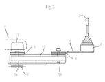
- Fig. 3 shows the movable supporting device 1 in a side view when the movable supporting device 1 is fixated to the armrest 8.
- the movable supporting device 1 comprises a first and second operable joint 5,6, each comprising a centrally placed rotation axis 9a,b, interconnected with a timing belt 11 such that the control assembly 2 creates a pantographic movement when the operable joints 5,6 are moved.
- the electrically releasable lock 7 is here placed on the rear operable joint 5, however it is equally conceivable that the electrically releasable lock 7 is placed on the frontal operable joint 6, or that the movable supporting device 1 comprises two electrically releasable locks, one located on the frontal operable joint 6 and one on the rear operable joint 5.
- the movable supporting device 1 is actively operable using an electric motor 13, which could enable a person to move the support even if the person is unable to push the movable supporting device 1 with muscular force.
- the electric motor 13 could for example be placed in the armrest 8 of a wheelchair and could be operated using a switch on the control assembly 2 or a switch placed in connection with the headrest or in a tongue control unit.
- Fig. 4 shows the motion track of the movable supporting device 1 of fig. 1 from above, displaying the pantographic movement made by the control assembly 2 by the connection with the two interlinked operable joints 5 and 6.
- the electrically releasable lock 7 is adapted to lock the movable supporting device 1 anywhere along its motion track and the pantographic movement guaranties that the control assembly 2 remains in the same orientation wherever it is locked.
- the control assembly 2 is a joystick controlling the movements of a wheelchair the direction that the joystick needs to be pushed in order for the wheelchair to travel foreword and backwards respectively, will be the same, no matter where the movable supporting device 1 to which the joystick 2 is mounted, is locked.
- the moveable supporting device 1 shown in fig. 4 is actively operable to crate said pantographic movement, e.g.by means of an electrical motor as shown with reference to fig. 3 .
Landscapes
- Health & Medical Sciences (AREA)
- Life Sciences & Earth Sciences (AREA)
- Animal Behavior & Ethology (AREA)
- General Health & Medical Sciences (AREA)
- Public Health (AREA)
- Veterinary Medicine (AREA)
- Handcart (AREA)
- Accommodation For Nursing Or Treatment Tables (AREA)
- Electric Propulsion And Braking For Vehicles (AREA)
Abstract
A movable supporting device for changing the position of a control assembly is provided. The movable supporting device comprises an operable joint and an electrically releasable lock. The operable joint is adapted to be locked by the electrically releasable lock.
Description
- The present invention relates generally to support devices for control assemblies.
- A control assembly in connection with a seat is most often mounted somewhere along the side of the seat, enabling the person to use the control assembly with one of the hands while seated in the seat. Having the control assembly being supported by a movable support device enables the control assembly to be adjusted such that the control assembly is placed in a desired position by the particular user of the seat. When using the control assembly the desired position is typically in front of the person on the right or left hand side, whereas when not using the control assembly, the desired position is typically in a retracted position further back or even behind the user. In
US5326063 a movable support device for controlling the position of a control assembly is disclosed. The movable support device ofUS5326063 allows the control assembly to be locked in a retracted and an extended position. - An electrically powered wheelchair is usually controlled by a control assembly, such as a joystick, a touch panel or a finger control assembly. In normal use, the electrically powered wheelchair is used as means of transportation as well as means for sitting when working, eating and interacting with other persons. When the electrically powered wheelchair is used as a means for transportation, control precision and comfort is of essence, why it is important that the control assembly can be positioned where the user desires. When, on the other hand, the electrically powered wheelchair is used as sitting means, especially at a table, it is highly desirable that the control assembly can be stowed away, not to interfere with the mobility or activities of the user.
- A user of an electrically powered wheelchair, usually have some sort of disability limiting the person's ability to move or limiting the muscular strength of that person. This makes it difficult for the person to move objects or to affect mechanical constructions with muscular strength. For non-disabled users it may be difficult to move a heavy control assembly with the precision required to position the control assembly in a desired position if the movable supporting device, to which the control assembly is mounted, should fixate the control assembly adequately in normal use.
- A movable supporting device for changing the position of a control assembly is provided. The movable supporting device comprises an operable joint and an electrically releasable lock. The operable joint is adapted to be locked by the electrically releasable lock such that the control assembly can be locked in a position along the motion track of the movable supporting member.
- According to one embodiment, the electrically releasable lock comprises an electromagnet which interacts with friction creating elements for locking the movable supporting device, such as an electromagnetic break.
- According to another embodiment, the operable joint of the movable supporting device is actively operable, e.g. by means of an electric motor. In other embodiments the movable supporting device further comprises a second operable joint, which may be interlinked with said first operable joint. The two operable joints could be interlinked using a timing belt.
- The movable supporting device could be adapted to create a pantographic movement of the control assembly, for always maintaining the orientation of the control assembly. The control assembly could be a mechanical, hydraulic, pneumatic or electric and could be in the form of for example a joystick, a leaver, a wheel, a knob or a touch panel.
- The movable supporting device could further comprise a switch for controlling the electrically releasable lock, which could be an electrical switch possible to operate without the use of large muscular force, which for example could be placed in connection with the control assembly for easy access by a user.
- According to one embodiment, the movable supporting device is movable along a motion track, and the electrically releasable lock is adapted to lock the movable supporting device anywhere along the motion track.
- It is furthermore conceivable that the movable supporting device, according to any one of the embodiments herein, further comprises a fixating element, which for example could be adapted to fixate the movable supporting device to an armrest.
- The invention is now described, by way of example, with reference to the accompanying drawings, in which:
-
Fig. 1 shows a movable supporting device mounted to the armrest of a wheelchair. -
Fig. 2 shows the movable supporting device offig. 1 in further detail in a see-through view. -
Fig. 3 shows the movable supporting device and a control assembly, according to another embodiment. -
Fig. 4 illustrates the motion track of a movable supporting device and control assembly. - In the following a detailed description of embodiments will be given. In the drawing figures, like reference numerals designate identical or corresponding elements throughout the several figures. It will be appreciated that these figures are for illustration only and are not in any way restricting the scope of the invention. Thus, any references to direction, such as "up" or "down", are only referring to the directions shown in the figures.
- An operable joint is to be understood as a joint connecting two or more parts in a way such that the two or more parts can be moved in relation to each other.
- A control assembly is to be understood as an assembly with the purpose of affecting the state or movement of a device, such as an electrical wheelchair or a construction crane. Examples of control assemblies are mechanical, pneumatic, hydraulic and electrical control assemblies which could be in the form of a joystick, a leaver, a wheel, a knob or a touch panel.
-
Fig. 1 shows the movable supporting device 1 according to an embodiment in which the movable supporting device 1 is fixated to thearmrest 8 of a wheelchair. The movable supporting device 1 is here adapted for changing the position of acontrol assembly 2, here being ajoystick 2. The movable supporting device 1 comprises a first and a second operable joint 5,6. The first operable joint 5 is in connection with thearmrest 8 of the wheelchair, whereas the second operable joint 6 is in connection with a supporting plate 4 supporting thecontrol assembly 2 fixated thereon. The two operable joints 5,6 may be interlinked through a timing belt (shown in greater detail infig. 2 ) which enables the movable supporting device 1 to perform a pantographic movement of thecontrol assembly 2 which renders the orientation of thecontrol assembly 2 unchanged when the movable supporting device 1 moves. The movable supporting device 1 further comprises an electrically releasable lock 7 in connection with the first operable joint 5 for locking the movement of the movable supporting device 1. According to the embodiment shown infig 1 , the electrically releasable lock 7 comprises an electromagnet which is operated by a switch 3 placed in connection with thecontrol assembly 2, for activating the electromagnet and thereby releasing the electrically releasable lock 7. When the electrically releasable lock 7 is released, the movable supporting device 1 is easily movable, almost without friction, and thereby is the position of thecontrol assembly 2 easy to alter, for example from a position suitable for operating the wheel chair, to a retracted position suitable for using the wheelchair as sitting means while eating. The electrically releasable lock according to the embodiment offig. 1 comprises multiple friction creating discs, which are pushed against each other by means of a spring member. An electromagnet is placed in connection with the friction creating discs and releases the force created by the spring when activated, thereby allowing the friction creating discs to move easily in relation to each other. According to other embodiments multiple such friction creating discs may be used for increasing the friction and hence the holding power of the electrically releasable lock 7 locking the movable supporting device 1. This particular embodiment of an electrically releasable lock 7 may of course, in any of the embodiments herein, be substituted to any other electrically releasable lock. Such electrically releasable locks are generally well known in the art. The movable supporting device is thereby movable, with use of very small force, when the releasable lock is released, and locked in a very firm hold, when the releasable lock is locked. -
Fig. 2 shows the movable supporting device 1 according tofig. 1 in further detail, where the first operable joint 5 comprises a centrally placed rotation axis 9a on to which aninner gear wheel 12a in connection with the timing belt 11 is fixated. The electrically releasable lock 7 is also fixated to the centrally placed rotation axis 9a and adapted to lock the centrally placed rotation axis 9a when in its locked state. By the connection with the timing belt 11, which interconnects the first centrally placed rotation axis 9a with the centrally placed rotation axis 9b of the second operable joint 6, the electrically releasable lock 7 also locks the second centrally placed rotation axis 9b. Thegear wheels 12a,b and the timing belt 11 is housed in ahousing 10 preferably made of a durable material such as aluminum or polyamide. - According to other embodiments (not shown), the movable supporting device 1 comprises two electrically releasable locks placed on the first centrally placed rotation axis 9a and the second centrally placed rotation axis 9b, respectively.
-
Fig. 3 shows the movable supporting device 1 in a side view when the movable supporting device 1 is fixated to thearmrest 8. The movable supporting device 1 comprises a first and second operable joint 5,6, each comprising a centrally placed rotation axis 9a,b, interconnected with a timing belt 11 such that thecontrol assembly 2 creates a pantographic movement when the operable joints 5,6 are moved. The electrically releasable lock 7 is here placed on the rear operable joint 5, however it is equally conceivable that the electrically releasable lock 7 is placed on the frontal operable joint 6, or that the movable supporting device 1 comprises two electrically releasable locks, one located on the frontal operable joint 6 and one on the rear operable joint 5. - The movable supporting device 1 according to the embodiment of
fig. 3 is actively operable using anelectric motor 13, which could enable a person to move the support even if the person is unable to push the movable supporting device 1 with muscular force. Theelectric motor 13 could for example be placed in thearmrest 8 of a wheelchair and could be operated using a switch on thecontrol assembly 2 or a switch placed in connection with the headrest or in a tongue control unit. -
Fig. 4 shows the motion track of the movable supporting device 1 offig. 1 from above, displaying the pantographic movement made by thecontrol assembly 2 by the connection with the two interlinked operable joints 5 and 6. The electrically releasable lock 7 is adapted to lock the movable supporting device 1 anywhere along its motion track and the pantographic movement guaranties that thecontrol assembly 2 remains in the same orientation wherever it is locked. In embodiments where thecontrol assembly 2 is a joystick controlling the movements of a wheelchair the direction that the joystick needs to be pushed in order for the wheelchair to travel foreword and backwards respectively, will be the same, no matter where the movable supporting device 1 to which thejoystick 2 is mounted, is locked. It is also conceivable that the moveable supporting device 1 shown infig. 4 is actively operable to crate said pantographic movement, e.g.by means of an electrical motor as shown with reference tofig. 3 . - Please note that any embodiment or part of embodiment or feature described herein may be combined in any way if such combination is not clearly contradictive.
Claims (12)
- A movable supporting device for changing the position of a control assembly, wherein said movable supporting device (1) comprises an operable joint (5;6) , characterized in that said movable supporting device (1) further comprises an electrically releasable lock (7), and wherein said operable joint (5;6) is adapted to be locked by said electrically releasable lock (7).
- The movable supporting device according to claim 1, wherein said electrically releasable lock (7) comprises an electromagnet.
- The movable supporting device according to any one of claims 1 and 2, wherein said operable joint (5;6) is actively operable.
- The movable supporting device according to claim 3, wherein said actively operable joint is actively operable using an electric motor (13).
- The movable supporting device according to any one of the preceding claims, wherein said movable supporting device (1) further comprises a second operable joint (5;6).
- The movable supporting device according to claim 5, wherein said two operable joints (5,6) are interlinked.
- The movable supporting device according to claim 6, wherein said two operable joints (5,6) are interlinked using a timing belt (11).
- The movable supporting device according to any one of claims 6 and 7, wherein said movable supporting device (1) is adapted to create a pantographic movement of said control assembly (2).
- The movable supporting device according to any one of the preceding claims, wherein said control assembly (2) is a joystick.
- The movable supporting device according to any one of the preceding claims, wherein said movable supporting device (1) further comprises a switch for controlling said electrically releasable lock (7).
- The movable supporting device according to any one of the preceding claims, wherein said movable supporting device (1) is movable along a motion track and wherein said electrically releasable lock (7) is adapted to lock said movable supporting device (1) anywhere along said motion track.
- The movable supporting device according to any one of the preceding claims, wherein said movable supporting device (1) further comprises a fixating element adapted to fixate said movable supporting device (1) to an armrest (8).
Priority Applications (1)
| Application Number | Priority Date | Filing Date | Title |
|---|---|---|---|
| EP09158285A EP2243452A1 (en) | 2009-04-20 | 2009-04-20 | Movable supporting device |
Applications Claiming Priority (1)
| Application Number | Priority Date | Filing Date | Title |
|---|---|---|---|
| EP09158285A EP2243452A1 (en) | 2009-04-20 | 2009-04-20 | Movable supporting device |
Publications (1)
| Publication Number | Publication Date |
|---|---|
| EP2243452A1 true EP2243452A1 (en) | 2010-10-27 |
Family
ID=41036068
Family Applications (1)
| Application Number | Title | Priority Date | Filing Date |
|---|---|---|---|
| EP09158285A Withdrawn EP2243452A1 (en) | 2009-04-20 | 2009-04-20 | Movable supporting device |
Country Status (1)
| Country | Link |
|---|---|
| EP (1) | EP2243452A1 (en) |
Cited By (5)
| Publication number | Priority date | Publication date | Assignee | Title |
|---|---|---|---|---|
| EP2870952A1 (en) * | 2013-11-11 | 2015-05-13 | Karma Medical Products Co., Ltd. | Controller shifting device |
| WO2016051541A1 (en) * | 2014-09-30 | 2016-04-07 | ヤマハ発動機株式会社 | Operation section-supporting structure for electrically driven wheelchair |
| WO2017056311A1 (en) * | 2015-10-02 | 2017-04-06 | ヤマハ発動機株式会社 | Drive operating part retaining structure and electric wheelchair |
| CN107468442A (en) * | 2017-09-11 | 2017-12-15 | 苏州诺乐智能科技有限公司 | A kind of electric wheelchair of double control switching |
| DE102018211194A1 (en) * | 2018-07-06 | 2020-01-09 | Meyra Gmbh | Swivel control device for a wheelchair |
Citations (7)
| Publication number | Priority date | Publication date | Assignee | Title |
|---|---|---|---|---|
| DE9011379U1 (en) * | 1990-08-03 | 1991-02-07 | Erber, Hans-Jürgen, 8311 Buch | Armrest with built-in TV-video combination |
| US5246240A (en) * | 1991-10-18 | 1993-09-21 | Romich Barry A | Apparatus for mounting equipment to wheelchairs |
| US5326063A (en) | 1992-06-30 | 1994-07-05 | Quickie Designs Inc. | Swing-away joystick assembly |
| US6688571B1 (en) * | 2001-10-12 | 2004-02-10 | Sunrise Medical Hhc Inc. | Adjustable joystick support and wheelchair therewith |
| US20040075329A1 (en) * | 2002-06-03 | 2004-04-22 | Cowen John R. | Pivotal joystick base |
| US20060229770A1 (en) * | 2005-04-12 | 2006-10-12 | Integrated Vision, Inc. | Moveable controls for vehicular applications |
| US7427078B1 (en) * | 2005-08-25 | 2008-09-23 | Humble Donald L | Wheelchair swing away system |
-
2009
- 2009-04-20 EP EP09158285A patent/EP2243452A1/en not_active Withdrawn
Patent Citations (7)
| Publication number | Priority date | Publication date | Assignee | Title |
|---|---|---|---|---|
| DE9011379U1 (en) * | 1990-08-03 | 1991-02-07 | Erber, Hans-Jürgen, 8311 Buch | Armrest with built-in TV-video combination |
| US5246240A (en) * | 1991-10-18 | 1993-09-21 | Romich Barry A | Apparatus for mounting equipment to wheelchairs |
| US5326063A (en) | 1992-06-30 | 1994-07-05 | Quickie Designs Inc. | Swing-away joystick assembly |
| US6688571B1 (en) * | 2001-10-12 | 2004-02-10 | Sunrise Medical Hhc Inc. | Adjustable joystick support and wheelchair therewith |
| US20040075329A1 (en) * | 2002-06-03 | 2004-04-22 | Cowen John R. | Pivotal joystick base |
| US20060229770A1 (en) * | 2005-04-12 | 2006-10-12 | Integrated Vision, Inc. | Moveable controls for vehicular applications |
| US7427078B1 (en) * | 2005-08-25 | 2008-09-23 | Humble Donald L | Wheelchair swing away system |
Cited By (5)
| Publication number | Priority date | Publication date | Assignee | Title |
|---|---|---|---|---|
| EP2870952A1 (en) * | 2013-11-11 | 2015-05-13 | Karma Medical Products Co., Ltd. | Controller shifting device |
| WO2016051541A1 (en) * | 2014-09-30 | 2016-04-07 | ヤマハ発動機株式会社 | Operation section-supporting structure for electrically driven wheelchair |
| WO2017056311A1 (en) * | 2015-10-02 | 2017-04-06 | ヤマハ発動機株式会社 | Drive operating part retaining structure and electric wheelchair |
| CN107468442A (en) * | 2017-09-11 | 2017-12-15 | 苏州诺乐智能科技有限公司 | A kind of electric wheelchair of double control switching |
| DE102018211194A1 (en) * | 2018-07-06 | 2020-01-09 | Meyra Gmbh | Swivel control device for a wheelchair |
Similar Documents
| Publication | Publication Date | Title |
|---|---|---|
| US8056874B2 (en) | Mounting and positioning apparatus for increased user independence | |
| EP2934322B1 (en) | Ultrasound system control panel and display lift | |
| US7600819B2 (en) | Armrest for use with a vehicle seat | |
| US10065531B2 (en) | Vehicle seat and method for adjusting a vehicle seat | |
| EP3556253A1 (en) | Furniture member with foldable pawl and ratchet assembly | |
| US20080084100A1 (en) | Synchronous office chair | |
| CA3044190C (en) | Chair | |
| KR100954226B1 (en) | Chair with a movable back support | |
| US10759318B2 (en) | Infinite adjustment mechanism for a head restraint | |
| US9066596B2 (en) | Seating assembly | |
| EP3578151B1 (en) | Backrest assembly and wheelchair therewith | |
| US7311360B2 (en) | Device for locking the configuration of equipment such as a vehicle seat | |
| KR20130027807A (en) | System for supporting movement for disabled person's drive | |
| EP2003012A3 (en) | Vehicle seats | |
| EP3802320A1 (en) | Seat assembly with independent seat bottom tilt | |
| KR200471109Y1 (en) | Apparatus for controlling the tilting of chair | |
| KR101838104B1 (en) | Chair typed device to assist standing up | |
| US20200245768A1 (en) | Posture adaptive work chair | |
| JP2002119347A (en) | Chair | |
| JP2016202824A (en) | Moving aid | |
| JP2008132298A (en) | Chair | |
| JP2007117113A (en) | wheelchair | |
| EP1750549B1 (en) | Chair seat with mutually moveable parts | |
| AU2006275207B2 (en) | A chair or a bed having a seat, a backrest and an armrest as well as use thereof | |
| JP2021139214A (en) | Assistance device |
Legal Events
| Date | Code | Title | Description |
|---|---|---|---|
| PUAI | Public reference made under article 153(3) epc to a published international application that has entered the european phase |
Free format text: ORIGINAL CODE: 0009012 |
|
| 17P | Request for examination filed |
Effective date: 20100916 |
|
| AK | Designated contracting states |
Kind code of ref document: A1 Designated state(s): AT BE BG CH CY CZ DE DK EE ES FI FR GB GR HR HU IE IS IT LI LT LU LV MC MK MT NL NO PL PT RO SE SI SK TR |
|
| 17Q | First examination report despatched |
Effective date: 20101013 |
|
| R17C | First examination report despatched (corrected) |
Effective date: 20110331 |
|
| STAA | Information on the status of an ep patent application or granted ep patent |
Free format text: STATUS: THE APPLICATION IS DEEMED TO BE WITHDRAWN |
|
| 18D | Application deemed to be withdrawn |
Effective date: 20111011 |