EP2242932B1 - A meridional fan - Google Patents
A meridional fan Download PDFInfo
- Publication number
- EP2242932B1 EP2242932B1 EP09701751.1A EP09701751A EP2242932B1 EP 2242932 B1 EP2242932 B1 EP 2242932B1 EP 09701751 A EP09701751 A EP 09701751A EP 2242932 B1 EP2242932 B1 EP 2242932B1
- Authority
- EP
- European Patent Office
- Prior art keywords
- fan
- tip
- blade
- fan according
- flange
- Prior art date
- Legal status (The legal status is an assumption and is not a legal conclusion. Google has not performed a legal analysis and makes no representation as to the accuracy of the status listed.)
- Active
Links
- 230000002093 peripheral effect Effects 0.000 claims description 4
- 239000000203 mixture Substances 0.000 claims description 2
- 230000000694 effects Effects 0.000 description 3
- 238000011144 upstream manufacturing Methods 0.000 description 3
- 238000000034 method Methods 0.000 description 2
- 238000009423 ventilation Methods 0.000 description 2
- WURBVZBTWMNKQT-UHFFFAOYSA-N 1-(4-chlorophenoxy)-3,3-dimethyl-1-(1,2,4-triazol-1-yl)butan-2-one Chemical compound C1=NC=NN1C(C(=O)C(C)(C)C)OC1=CC=C(Cl)C=C1 WURBVZBTWMNKQT-UHFFFAOYSA-N 0.000 description 1
- 230000002411 adverse Effects 0.000 description 1
- 238000004378 air conditioning Methods 0.000 description 1
- 230000009172 bursting Effects 0.000 description 1
- AAOVKJBEBIDNHE-UHFFFAOYSA-N diazepam Chemical compound N=1CC(=O)N(C)C2=CC=C(Cl)C=C2C=1C1=CC=CC=C1 AAOVKJBEBIDNHE-UHFFFAOYSA-N 0.000 description 1
- 238000010438 heat treatment Methods 0.000 description 1
- 238000009434 installation Methods 0.000 description 1
- 230000001788 irregular Effects 0.000 description 1
- 238000004519 manufacturing process Methods 0.000 description 1
Images

Classifications
-
- F—MECHANICAL ENGINEERING; LIGHTING; HEATING; WEAPONS; BLASTING
- F04—POSITIVE - DISPLACEMENT MACHINES FOR LIQUIDS; PUMPS FOR LIQUIDS OR ELASTIC FLUIDS
- F04D—NON-POSITIVE-DISPLACEMENT PUMPS
- F04D29/00—Details, component parts, or accessories
- F04D29/26—Rotors specially for elastic fluids
- F04D29/32—Rotors specially for elastic fluids for axial flow pumps
- F04D29/38—Blades
- F04D29/384—Blades characterised by form
-
- F—MECHANICAL ENGINEERING; LIGHTING; HEATING; WEAPONS; BLASTING
- F04—POSITIVE - DISPLACEMENT MACHINES FOR LIQUIDS; PUMPS FOR LIQUIDS OR ELASTIC FLUIDS
- F04D—NON-POSITIVE-DISPLACEMENT PUMPS
- F04D29/00—Details, component parts, or accessories
- F04D29/66—Combating cavitation, whirls, noise, vibration or the like; Balancing
- F04D29/68—Combating cavitation, whirls, noise, vibration or the like; Balancing by influencing boundary layers
- F04D29/681—Combating cavitation, whirls, noise, vibration or the like; Balancing by influencing boundary layers especially adapted for elastic fluid pumps
Definitions
- the present invention relates to meridional fans, particularly but not exclusively, to axial flow fans for large scale air ventilation and/or heating purposes in industrial buildings, industrial air conditioning units, underground railway systems and similar large infrastructures.
- Such fans are typically located in a duct system and it is desirable for efficiency purposes for the area swept by the fan blades to be located in a cylindrical ring part of the duct system with a minimal clearance between the tips of the fan blades and the surface of the cylindrical ring.
- the outer surface of the tips of the fan blades have a contour in the form of an arc corresponding to the circle swept by the fan blades.
- the fan aerodynamic work input establishes a higher pressure downstream of the fan than upstream.
- the pressure rise is obtained by means of aerodynamic forces at play when the air flows about the rotor blades.
- Owing to the design of the blade a pressure difference is established between the blade pressure surface or side and its suction surface or side. The result of this pressure difference means that air tends to spill back over the tip of the fan from the high pressure to the low-pressure side. This air movement reduces the efficiency of the fan and also increases the noise generated by the fan.
- a known method for reducing the amount of flow back air is to keep the gap between the fan tips and the cylindrical ring to a minimum and also to extend the length of the gap by incorporating on the tip of each blade an extending flange which increases the length of the gap in the direction of the leakage flow and thereby increases the resistance to flow back through the gap.
- the present invention seeks to provide an improved form of a fan blade tip which increases the efficiency of the fan and at the same time reduces the noise generated by the fan.
- the fan tips have, in the past, been made as a uniform as possible, but it has now, surprisingly, been discovered that a non uniform profile for certain sections of the blade tip can be advantageous in increasing the efficiency of the fan, reducing the power required to drive the fan at a given speed and pressure, and at the same time reducing the noise generated by the fan.
- the uniform profile of the known conventional blade tips lead to the generation of tight vortices at the blade tip and it is believed that these vortices, when they reach a critical state suddenly expand very rapidly, to the extent of provoking vortex bursting or collapse, which generates a great deal of turbulence. This adverse effect is amplified if the vortices impinge on an adjacent fan blade at which point they burst on impact.
- GB 2050530 (Papst) (D3) discloses an axial fan for impelling air through a duct and has a plurality of fan blades with peripheral blade tips having a leading edge, a trailing edge and a tip outer surface defining a leakage path between the tip and the duct ring.
- the tip has a flange extending in the axial direction, but the whole tenor of the specification is that this is on the upstream side and it is entirely fortuitous that, for manufacturing reasons, certain embodiments have the tip extending onto the downstream high-pressure side as well. However there is no disclosure or teaching in the specification that it is important that the tip flange and hence the leakage path should extend into the high-pressure side.
- FR 2753495 (Valeo) (D2) discloses a fan rotatable in a duct and in the leakage path between the outer tips of the fan blades and the duct provides means in the form of protuberances to minimise the width of the leakage path. There is no teaching of the desirability of having the leakage path on the high-pressure side nor the advantages of having a non-uniform leading edge.
- a meridional fan adapted to be rotatably mounted in a duct ring of circular cross section for impelling air through the duct, and having a plurality of fan blades with peripheral blade tips having a width defining an arc with a circumferential extent describing, in operation, a circular path adjacent the duct ring, the blade tips each having a leading edge, a trailing edge and a tip outer surface, a leakage path being formed between the tip outer surface and the duct ring, at least one of the edges and/or the outer surface having a non-uniform profile for influencing the flow of air through the flow leakage path, characterised in that the or each tip has a flange extending in the axial direction on the downstream, high pressure side of the fan, which increases the length of the leakage flow path and wherein the leading edge of the flange has a non-uniform profile so that the circumferential axial extent of the leading edge of the flange varies along the width of the blade
- the leading edge of the flange has an undulating profile.
- the trailing edge of the blade tip includes a stepped shoulder extending at least partially across the width of the blade tip.
- the stepped shoulder consists of a plurality of stepped recesses spaced across the width of the blade tip. These stepped recesses preferably are regularly spaced, but may be irregularly spaced.
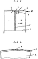
- Figure 3 illustrates a schematic cross-section through the axis of the fan and cylindrical ring 3 illustrating the peripheral flange 5 with its non-uniform leading edge 6.
- the flange extends axially downstream on the high pressure side of the fan blade.
- the effect of the high pressure on the blade pressure side means that air tends to spill backwards at the periphery of the fan tips through the gap between the fan tip 4 and the cylindrical ring 3 as illustrated by the arrow 7.
- the gap thus forms a leakage flow path for air to flow from the high pressure, downstream side of the blade back to the upstream low pressure side and it is desirable to reduce this flow to a minimum.
- the maximum pressure on the downside of the fan occurs in the boundary layer adjacent the fan face.
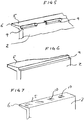
- Figure 4 illustrates a scrap view of a fan blade 2 and its tip 4 in the direction of the arrow B in which the outer surface 8 of the tip has a non uniform profile in the circumferential direction formed by undulations. These undulations may be regular or irregular in size.
- Figure 6 illustrates an alternative embodiment of a rear view of the blade tip in which a continuous stepped shoulder 9 is provided across the full width of the fan blade.
- the peripherally extending flange 5 has a non-uniform dimension in the circumferential direction formed by a gradual curving of the leading edge 6.
- the variation in the circumferential extent of the flange may be formed in a stepped manner with regular or irregularly spaced steps.
Description
- The present invention relates to meridional fans, particularly but not exclusively, to axial flow fans for large scale air ventilation and/or heating purposes in industrial buildings, industrial air conditioning units, underground railway systems and similar large infrastructures.
- Such fans are typically located in a duct system and it is desirable for efficiency purposes for the area swept by the fan blades to be located in a cylindrical ring part of the duct system with a minimal clearance between the tips of the fan blades and the surface of the cylindrical ring. To achieve this, the outer surface of the tips of the fan blades have a contour in the form of an arc corresponding to the circle swept by the fan blades.
- In operation, the fan aerodynamic work input establishes a higher pressure downstream of the fan than upstream. The pressure rise is obtained by means of aerodynamic forces at play when the air flows about the rotor blades. Owing to the design of the blade a pressure difference is established between the blade pressure surface or side and its suction surface or side. The result of this pressure difference means that air tends to spill back over the tip of the fan from the high pressure to the low-pressure side. This air movement reduces the efficiency of the fan and also increases the noise generated by the fan. A known method for reducing the amount of flow back air is to keep the gap between the fan tips and the cylindrical ring to a minimum and also to extend the length of the gap by incorporating on the tip of each blade an extending flange which increases the length of the gap in the direction of the leakage flow and thereby increases the resistance to flow back through the gap.
- The present invention seeks to provide an improved form of a fan blade tip which increases the efficiency of the fan and at the same time reduces the noise generated by the fan.
- Intuitively, the fan tips have, in the past, been made as a uniform as possible, but it has now, surprisingly, been discovered that a non uniform profile for certain sections of the blade tip can be advantageous in increasing the efficiency of the fan, reducing the power required to drive the fan at a given speed and pressure, and at the same time reducing the noise generated by the fan. The uniform profile of the known conventional blade tips lead to the generation of tight vortices at the blade tip and it is believed that these vortices, when they reach a critical state suddenly expand very rapidly, to the extent of provoking vortex bursting or collapse, which generates a great deal of turbulence. This adverse effect is amplified if the vortices impinge on an adjacent fan blade at which point they burst on impact.
-
GB 2050530 -
FR 2753495 -
DE 3234011 (D4) andUS 4089618 (D5) disclose fans in which trailing radial edges of the fan blades have a non-uniform profile to generate turbulence to reduce noise. However both patents are silent on the feature of leakage paths between the tips of the fan blades and the casing..US 2003/095864 (D6) discloses a fan in which the outer tips of the fan blades have an end piece which extends axially in both directions of the fan blade to break up blade end vortex. There is no discussion or teaching of the leakage path or the problems associated with such an arrangement. There is also no discussion of the advantages of using non-uniform profiles for the edges of the end faces. - According to the present invention there is provided a meridional fan adapted to be rotatably mounted in a duct ring of circular cross section for impelling air through the duct, and having a plurality of fan blades with peripheral blade tips having a width defining an arc with a circumferential extent describing, in operation, a circular path adjacent the duct ring, the blade tips each having a leading edge, a trailing edge and a tip outer surface, a leakage path being formed between the tip outer surface and the duct ring, at least one of the edges and/or the outer surface having a non-uniform profile for influencing the flow of air through the flow leakage path, characterised in that the or each tip has a flange extending in the axial direction on the downstream, high pressure side of the fan, which increases the length of the leakage flow path and wherein the leading edge of the flange has a non-uniform profile so that the circumferential axial extent of the leading edge of the flange varies along the width of the blade tip..
- Preferably, the leading edge of the flange has an undulating profile. In a further embodiment, the trailing edge of the blade tip includes a stepped shoulder extending at least partially across the width of the blade tip. In one form, the stepped shoulder consists of a plurality of stepped recesses spaced across the width of the blade tip. These stepped recesses preferably are regularly spaced, but may be irregularly spaced.
- In a preferred embodiment, the outer tip surface has a non-uniform profile in the circumferential direction. Preferably the non-uniform profile may be formed by undulations or by grooves or a mixture thereof in the outer surface. The undulations and grooves may extend partially or completely along the axial extent of the outer surface. In a further embodiment (not shown) the fan tip includes a plurality of holes or perforations.
- Preferred embodiments of the present invention will now be described by way of example, with reference to the accompanying drawings in which:-
-
Figure 1 shows an axial view of an axial fan having four blades located in a cylindrical casing, -
Figure 2 shows a radially inward view of a fan blade, -
Figure 3 shows an axial section of a fan blade and the cylindrical casing, -
Figure 4 shows a scrap of view of a fan blade in the direction of the Arrow B shown inFigure 3 , -
Figure 5 shows a scrap view of the trailing edge of a fan blade, -
Figure 6 shows a corresponding view of the trailing edge of a further embodiment, and -
Figure 7 shows a scrap view of the outer surface of a further embodiment of blade tip. - Referring now to
Figure 1 , there is shown an axial view of an axial flow fan having fourfan blades 2 mounted for rotation about anaxis 1 of acylindrical ring part 3 of a duct system of an air ventilation system. The area swept by the fan is such that theblade tips 4 are very close to thecylindrical ring 3 with only a minimal gap there between. To minimise this gap, the outer surfaces of theblade tips 4 have an arcuate contour defined by the circle swept by theblades 2. - Referring now to
Figure 2 also, it can be seen that the fan blade has on its tip aflange 5 serving to increase the circumferential extent of the gap between the outer surface of the tip and thecylindrical ring 3 to increase the resistance of airflow through the gap. In this embodiment it can be seen that theedge 6 of theflange 5 has a undulating, non-uniform profile in the circumferential direction and at one end of the tip the outer surface is cut away to provide a non-uniform outer surface for the tip. -
Figure 3 illustrates a schematic cross-section through the axis of the fan andcylindrical ring 3 illustrating theperipheral flange 5 with its non-uniform leadingedge 6. The flange extends axially downstream on the high pressure side of the fan blade. The effect of the high pressure on the blade pressure side means that air tends to spill backwards at the periphery of the fan tips through the gap between thefan tip 4 and thecylindrical ring 3 as illustrated by the arrow 7. The gap thus forms a leakage flow path for air to flow from the high pressure, downstream side of the blade back to the upstream low pressure side and it is desirable to reduce this flow to a minimum. The maximum pressure on the downside of the fan occurs in the boundary layer adjacent the fan face. Centrifugal force tends to drive the boundary layer up towards the fan tip and it has been found is that with the flange the boundary layer is deflected and dissipated with the effect that the pressure at the entrance to the leakage path is lower than it otherwise would be. -
Figure 4 illustrates a scrap view of afan blade 2 and itstip 4 in the direction of the arrow B in which theouter surface 8 of the tip has a non uniform profile in the circumferential direction formed by undulations. These undulations may be regular or irregular in size. -
Figure 5 illustrates a schematic view of thefan blade tip 4 having on the low-pressure side a series of cutaway steppedshoulders 9 or recesses which serve to decelerate abruptly the airflow as it exits the gap between theblade tip 4 and thecylindrical ring 3. These recesses may be regularly spaced, of a regular size or may be irregularly spaced and irregularly sized. -
Figure 6 illustrates an alternative embodiment of a rear view of the blade tip in which a continuousstepped shoulder 9 is provided across the full width of the fan blade. In this embodiment, the peripherally extendingflange 5 has a non-uniform dimension in the circumferential direction formed by a gradual curving of the leadingedge 6. In another embodiment, not shown, the variation in the circumferential extent of the flange may be formed in a stepped manner with regular or irregularly spaced steps. -
Figure 7 shows a further embodiment in which the outer surface of the forwardly extending flange has a plurality of spaced recesses or grooves which may or may not extend through to the leading edge or trailing edge of the outer surface. - It will be appreciated that the different methods of providing a non-uniform profile for the outer surface, leading and trailing edges of the blade tip may be used individually or in any combination depending upon the particular size, design speed, number of blades etc of a particular fan. In this connection, although the specific embodiment shows a fan with four blades, it will be understood that the number of blades may vary depending upon the design parameters of the particular installation. Other forms of non-uniformity, such as a circumferential channel in the outer surface of the tip, may be provided. Although the described embodiment is an axial flow fan, the invention is also applicable to mixed flow fans. In such applications, the duct ring is not necessarily cylindrical but could be conical or have a diameter that increases exponentially.
Claims (9)
- A meridional fan adapted to be rotatably mounted in a duct ring (3) of circular cross section for impelling air through the duct, and having a plurality of fan blades (2) with peripheral blade tips (4) having a width defining an arc with a circumferential extent describing, in operation, a circular path adjacent the duct ring (3), the blade tips (4) each having a leading edge (6), a trailing edge (9) and a tip outer surface (8), a leakage path being formed between the tip outer surface (8) and the duct ring (3), at least one of the edges (6) and/or the outer surface (8) having a non-uniform profile for influencing the flow of air through the flow leakage path, characterised in that:the or each tip (4) has a flange (5) extending in the axial direction on the downstream, high pressure side of the fan, which increases the length of the leakage flow path, and wherein the leading edge (6) of the flange (5) has a non-uniform profile so that the circumferential axial extent of the leading edge (6} of the flange (5) varies along the width of the blade tip..
- A fan according to claim 1, wherein the leading edge (6) of the flange has an undulating profile.
- A fan according to claim 1, or 2, wherein the trailing edge of the fan tip includes a stepped shoulder (9) extending at least partially across the width of the blade tip (3).
- A fan according to claim 3, wherein the stepped shoulder (9) comprises a plurality of stepped recesses spaced across the width of the blade tip.
- A fan according to claim 5, wherein the stepped recesses (9) are regularly spaced across the width of the blade tip.
- A fan according to any one of the preceding claims, wherein the outer tip surface (8) has a non-uniform profile in the circumferential direction.
- A fan according to any one of the preceding claims wherein the outer tip surface (8) has a non-uniform profile in the axial direction.
- A fan according to claim 6 or 7, wherein the non-uniform profile is formed by undulations or by grooves (10) or a mixture thereof.
- A fan according to claim 9, wherein the undulations and/or grooves (10) extend partially or completely along the axial extent of the outer surface.
Applications Claiming Priority (2)
| Application Number | Priority Date | Filing Date | Title |
|---|---|---|---|
| GB0800582A GB2452104B (en) | 2008-01-14 | 2008-01-14 | A meridional fan |
| PCT/GB2009/000088 WO2009090376A1 (en) | 2008-01-14 | 2009-01-13 | A meridional fan |
Publications (2)
| Publication Number | Publication Date |
|---|---|
| EP2242932A1 EP2242932A1 (en) | 2010-10-27 |
| EP2242932B1 true EP2242932B1 (en) | 2017-07-12 |
Family
ID=39144868
Family Applications (1)
| Application Number | Title | Priority Date | Filing Date |
|---|---|---|---|
| EP09701751.1A Active EP2242932B1 (en) | 2008-01-14 | 2009-01-13 | A meridional fan |
Country Status (4)
| Country | Link |
|---|---|
| EP (1) | EP2242932B1 (en) |
| ES (1) | ES2636989T3 (en) |
| GB (1) | GB2452104B (en) |
| WO (1) | WO2009090376A1 (en) |
Families Citing this family (4)
| Publication number | Priority date | Publication date | Assignee | Title |
|---|---|---|---|---|
| TWI443262B (en) * | 2010-12-29 | 2014-07-01 | Delta Electronics Inc | Fan and impeller thereof |
| EP2530330B1 (en) * | 2011-06-01 | 2016-05-25 | MTU Aero Engines AG | Rotor blade for the compressor of a turbo engine, compressor and turbo machine |
| US10422349B2 (en) | 2014-07-08 | 2019-09-24 | Daikin Industries, Ltd. | Propeller fan and blower unit |
| CN108087330A (en) * | 2017-11-27 | 2018-05-29 | 珠海格力电器股份有限公司 | Blade construction and with its air conditioner |
Citations (1)
| Publication number | Priority date | Publication date | Assignee | Title |
|---|---|---|---|---|
| US20030095864A1 (en) * | 2001-11-19 | 2003-05-22 | Borislav Ivanovic | Fan with reduced noise |
Family Cites Families (10)
| Publication number | Priority date | Publication date | Assignee | Title |
|---|---|---|---|---|
| JPS5115210A (en) * | 1974-07-02 | 1976-02-06 | Rotoron Inc | Zatsuongenshono fuan |
| DE3017226A1 (en) * | 1979-05-12 | 1980-11-20 | Papst Motoren Kg | FAN BLADE |
| DE3234011A1 (en) * | 1982-09-14 | 1984-03-15 | Braun Ag, 6000 Frankfurt | Axial fan |
| JPS59185898A (en) * | 1983-04-08 | 1984-10-22 | Aisin Seiki Co Ltd | Fan blade |
| SU1339308A1 (en) * | 1986-04-14 | 1987-09-23 | Всесоюзный Научно-Исследовательский И Проектно-Конструкторский Институт По Оборудованию Для Кондиционирования Воздуха И Вентиляции | Axial-flow fan blade |
| JPH01106998A (en) * | 1987-10-20 | 1989-04-24 | Seiko Electronic Components Ltd | Shape of fan of axial flow blower |
| FR2753495B1 (en) * | 1996-09-19 | 1998-11-13 | Valeo Thermique Moteur Sa | FAN, IN PARTICULAR FOR A COOLING AND / OR HEATING AND / OR AIR CONDITIONING APPARATUS OF A MOTOR VEHICLE |
| JPH10148199A (en) * | 1996-11-18 | 1998-06-02 | Mitsubishi Heavy Ind Ltd | Axial flow fan device |
| DE10352253A1 (en) * | 2003-11-08 | 2005-06-09 | Alstom Technology Ltd | Compressor blade |
| US20060034697A1 (en) * | 2004-08-12 | 2006-02-16 | Cheng-Kang Chen | Propeller structure of a fan |
-
2008
- 2008-01-14 GB GB0800582A patent/GB2452104B/en active Active
-
2009
- 2009-01-13 EP EP09701751.1A patent/EP2242932B1/en active Active
- 2009-01-13 WO PCT/GB2009/000088 patent/WO2009090376A1/en active Application Filing
- 2009-01-13 ES ES09701751.1T patent/ES2636989T3/en active Active
Patent Citations (1)
| Publication number | Priority date | Publication date | Assignee | Title |
|---|---|---|---|---|
| US20030095864A1 (en) * | 2001-11-19 | 2003-05-22 | Borislav Ivanovic | Fan with reduced noise |
Also Published As
| Publication number | Publication date |
|---|---|
| EP2242932A1 (en) | 2010-10-27 |
| ES2636989T3 (en) | 2017-10-10 |
| WO2009090376A1 (en) | 2009-07-23 |
| GB2452104B (en) | 2009-07-22 |
| GB0800582D0 (en) | 2008-02-20 |
| GB2452104A (en) | 2009-02-25 |
Similar Documents
| Publication | Publication Date | Title |
|---|---|---|
| US8568095B2 (en) | Reduced tip clearance losses in axial flow fans | |
| US8308420B2 (en) | Centrifugal compressor, impeller and operating method of the same | |
| EP2097313B1 (en) | Axial fan casing design with circumferentially spaced wedges | |
| EP2943689B1 (en) | Shrouded axial fan with casing treatment | |
| EP2230407A1 (en) | Propeller fan | |
| US9885368B2 (en) | Stall margin enhancement of axial fan with rotating shroud | |
| EP2096320B1 (en) | Cascade of axial compressor | |
| WO2011062062A1 (en) | Multi-blade fan for centrifugal blower | |
| US20100226767A1 (en) | Diffuser arrangement | |
| CN102536893A (en) | Air cycle machine compressor rotor | |
| US8622695B2 (en) | Flow trim for vane-axial fans | |
| EP2242932B1 (en) | A meridional fan | |
| JP2011137463A (en) | System and apparatus relating to compressor stator blade and diffuser of turbine engine | |
| US20210123444A1 (en) | Mixed-flow compressor configuration for a refrigeration system | |
| CN110319054B (en) | Impeller for forward centrifugal fan | |
| US9523370B2 (en) | Blower with curved blades | |
| CN112840128A (en) | Diagonal fan with optimized diagonal impeller | |
| CA3052525A1 (en) | Compressor diffuser with plasma actuators | |
| US6139273A (en) | Radial flow fan | |
| JP2009041373A (en) | Turbo compressor | |
| WO2015094940A1 (en) | Blower assembly including a noise attenuating impeller | |
| WO2008082397A1 (en) | Reduced tip clearance losses in axial flow fans | |
| KR102569738B1 (en) | Diffusers for radial compressors | |
| JP3578692B2 (en) | Turbo compressor | |
| KR100802022B1 (en) | Turbofan |
Legal Events
| Date | Code | Title | Description |
|---|---|---|---|
| PUAI | Public reference made under article 153(3) epc to a published international application that has entered the european phase |
Free format text: ORIGINAL CODE: 0009012 |
|
| 17P | Request for examination filed |
Effective date: 20100816 |
|
| AK | Designated contracting states |
Kind code of ref document: A1 Designated state(s): AT BE BG CH CY CZ DE DK EE ES FI FR GB GR HR HU IE IS IT LI LT LU LV MC MK MT NL NO PL PT RO SE SI SK TR |
|
| AX | Request for extension of the european patent |
Extension state: AL BA RS |
|
| DAX | Request for extension of the european patent (deleted) | ||
| RBV | Designated contracting states (corrected) |
Designated state(s): AT BE BG CH CY CZ DE DK EE ES FI FR GR HR HU IE IS IT LI LT LU LV MC MK MT NL NO PL PT RO SE SI SK TR |
|
| 17Q | First examination report despatched |
Effective date: 20150119 |
|
| GRAP | Despatch of communication of intention to grant a patent |
Free format text: ORIGINAL CODE: EPIDOSNIGR1 |
|
| INTG | Intention to grant announced |
Effective date: 20160901 |
|
| GRAS | Grant fee paid |
Free format text: ORIGINAL CODE: EPIDOSNIGR3 |
|
| GRAA | (expected) grant |
Free format text: ORIGINAL CODE: 0009210 |
|
| AK | Designated contracting states |
Kind code of ref document: B1 Designated state(s): AT BE BG CH CY CZ DE DK EE ES FI FR GR HR HU IE IS IT LI LT LU LV MC MK MT NL NO PL PT RO SE SI SK TR |
|
| RAP1 | Party data changed (applicant data changed or rights of an application transferred) |
Owner name: HOWDEN AXIAL FANS AB |
|
| REG | Reference to a national code |
Ref country code: CH Ref legal event code: EP |
|
| REG | Reference to a national code |
Ref country code: AT Ref legal event code: REF Ref document number: 908626 Country of ref document: AT Kind code of ref document: T Effective date: 20170715 |
|
| REG | Reference to a national code |
Ref country code: IE Ref legal event code: FG4D |
|
| REG | Reference to a national code |
Ref country code: NL Ref legal event code: FP |
|
| REG | Reference to a national code |
Ref country code: DE Ref legal event code: R096 Ref document number: 602009047069 Country of ref document: DE |
|
| REG | Reference to a national code |
Ref country code: ES Ref legal event code: FG2A Ref document number: 2636989 Country of ref document: ES Kind code of ref document: T3 Effective date: 20171010 |
|
| REG | Reference to a national code |
Ref country code: LT Ref legal event code: MG4D |
|
| REG | Reference to a national code |
Ref country code: FR Ref legal event code: PLFP Year of fee payment: 10 |
|
| PG25 | Lapsed in a contracting state [announced via postgrant information from national office to epo] |
Ref country code: LT Free format text: LAPSE BECAUSE OF FAILURE TO SUBMIT A TRANSLATION OF THE DESCRIPTION OR TO PAY THE FEE WITHIN THE PRESCRIBED TIME-LIMIT Effective date: 20170712 Ref country code: HR Free format text: LAPSE BECAUSE OF FAILURE TO SUBMIT A TRANSLATION OF THE DESCRIPTION OR TO PAY THE FEE WITHIN THE PRESCRIBED TIME-LIMIT Effective date: 20170712 Ref country code: SE Free format text: LAPSE BECAUSE OF FAILURE TO SUBMIT A TRANSLATION OF THE DESCRIPTION OR TO PAY THE FEE WITHIN THE PRESCRIBED TIME-LIMIT Effective date: 20170712 Ref country code: FI Free format text: LAPSE BECAUSE OF FAILURE TO SUBMIT A TRANSLATION OF THE DESCRIPTION OR TO PAY THE FEE WITHIN THE PRESCRIBED TIME-LIMIT Effective date: 20170712 Ref country code: NO Free format text: LAPSE BECAUSE OF FAILURE TO SUBMIT A TRANSLATION OF THE DESCRIPTION OR TO PAY THE FEE WITHIN THE PRESCRIBED TIME-LIMIT Effective date: 20171012 |
|
| PG25 | Lapsed in a contracting state [announced via postgrant information from national office to epo] |
Ref country code: LV Free format text: LAPSE BECAUSE OF FAILURE TO SUBMIT A TRANSLATION OF THE DESCRIPTION OR TO PAY THE FEE WITHIN THE PRESCRIBED TIME-LIMIT Effective date: 20170712 Ref country code: IS Free format text: LAPSE BECAUSE OF FAILURE TO SUBMIT A TRANSLATION OF THE DESCRIPTION OR TO PAY THE FEE WITHIN THE PRESCRIBED TIME-LIMIT Effective date: 20171112 Ref country code: BG Free format text: LAPSE BECAUSE OF FAILURE TO SUBMIT A TRANSLATION OF THE DESCRIPTION OR TO PAY THE FEE WITHIN THE PRESCRIBED TIME-LIMIT Effective date: 20171012 Ref country code: GR Free format text: LAPSE BECAUSE OF FAILURE TO SUBMIT A TRANSLATION OF THE DESCRIPTION OR TO PAY THE FEE WITHIN THE PRESCRIBED TIME-LIMIT Effective date: 20171013 Ref country code: PL Free format text: LAPSE BECAUSE OF FAILURE TO SUBMIT A TRANSLATION OF THE DESCRIPTION OR TO PAY THE FEE WITHIN THE PRESCRIBED TIME-LIMIT Effective date: 20170712 |
|
| REG | Reference to a national code |
Ref country code: DE Ref legal event code: R097 Ref document number: 602009047069 Country of ref document: DE |
|
| PG25 | Lapsed in a contracting state [announced via postgrant information from national office to epo] |
Ref country code: RO Free format text: LAPSE BECAUSE OF FAILURE TO SUBMIT A TRANSLATION OF THE DESCRIPTION OR TO PAY THE FEE WITHIN THE PRESCRIBED TIME-LIMIT Effective date: 20170712 Ref country code: DK Free format text: LAPSE BECAUSE OF FAILURE TO SUBMIT A TRANSLATION OF THE DESCRIPTION OR TO PAY THE FEE WITHIN THE PRESCRIBED TIME-LIMIT Effective date: 20170712 Ref country code: CZ Free format text: LAPSE BECAUSE OF FAILURE TO SUBMIT A TRANSLATION OF THE DESCRIPTION OR TO PAY THE FEE WITHIN THE PRESCRIBED TIME-LIMIT Effective date: 20170712 |
|
| PLBE | No opposition filed within time limit |
Free format text: ORIGINAL CODE: 0009261 |
|
| STAA | Information on the status of an ep patent application or granted ep patent |
Free format text: STATUS: NO OPPOSITION FILED WITHIN TIME LIMIT |
|
| PG25 | Lapsed in a contracting state [announced via postgrant information from national office to epo] |
Ref country code: EE Free format text: LAPSE BECAUSE OF FAILURE TO SUBMIT A TRANSLATION OF THE DESCRIPTION OR TO PAY THE FEE WITHIN THE PRESCRIBED TIME-LIMIT Effective date: 20170712 Ref country code: SK Free format text: LAPSE BECAUSE OF FAILURE TO SUBMIT A TRANSLATION OF THE DESCRIPTION OR TO PAY THE FEE WITHIN THE PRESCRIBED TIME-LIMIT Effective date: 20170712 Ref country code: IT Free format text: LAPSE BECAUSE OF FAILURE TO SUBMIT A TRANSLATION OF THE DESCRIPTION OR TO PAY THE FEE WITHIN THE PRESCRIBED TIME-LIMIT Effective date: 20170712 |
|
| 26N | No opposition filed |
Effective date: 20180413 |
|
| PG25 | Lapsed in a contracting state [announced via postgrant information from national office to epo] |
Ref country code: SI Free format text: LAPSE BECAUSE OF FAILURE TO SUBMIT A TRANSLATION OF THE DESCRIPTION OR TO PAY THE FEE WITHIN THE PRESCRIBED TIME-LIMIT Effective date: 20170712 |
|
| PG25 | Lapsed in a contracting state [announced via postgrant information from national office to epo] |
Ref country code: LU Free format text: LAPSE BECAUSE OF NON-PAYMENT OF DUE FEES Effective date: 20180113 |
|
| REG | Reference to a national code |
Ref country code: IE Ref legal event code: MM4A |
|
| REG | Reference to a national code |
Ref country code: BE Ref legal event code: MM Effective date: 20180131 |
|
| PG25 | Lapsed in a contracting state [announced via postgrant information from national office to epo] |
Ref country code: BE Free format text: LAPSE BECAUSE OF NON-PAYMENT OF DUE FEES Effective date: 20180131 |
|
| PG25 | Lapsed in a contracting state [announced via postgrant information from national office to epo] |
Ref country code: IE Free format text: LAPSE BECAUSE OF NON-PAYMENT OF DUE FEES Effective date: 20180113 |
|
| PG25 | Lapsed in a contracting state [announced via postgrant information from national office to epo] |
Ref country code: MC Free format text: LAPSE BECAUSE OF FAILURE TO SUBMIT A TRANSLATION OF THE DESCRIPTION OR TO PAY THE FEE WITHIN THE PRESCRIBED TIME-LIMIT Effective date: 20170712 |
|
| PG25 | Lapsed in a contracting state [announced via postgrant information from national office to epo] |
Ref country code: MT Free format text: LAPSE BECAUSE OF NON-PAYMENT OF DUE FEES Effective date: 20180113 |
|
| PG25 | Lapsed in a contracting state [announced via postgrant information from national office to epo] |
Ref country code: TR Free format text: LAPSE BECAUSE OF FAILURE TO SUBMIT A TRANSLATION OF THE DESCRIPTION OR TO PAY THE FEE WITHIN THE PRESCRIBED TIME-LIMIT Effective date: 20170712 |
|
| PG25 | Lapsed in a contracting state [announced via postgrant information from national office to epo] |
Ref country code: PT Free format text: LAPSE BECAUSE OF FAILURE TO SUBMIT A TRANSLATION OF THE DESCRIPTION OR TO PAY THE FEE WITHIN THE PRESCRIBED TIME-LIMIT Effective date: 20170712 Ref country code: HU Free format text: LAPSE BECAUSE OF FAILURE TO SUBMIT A TRANSLATION OF THE DESCRIPTION OR TO PAY THE FEE WITHIN THE PRESCRIBED TIME-LIMIT; INVALID AB INITIO Effective date: 20090113 |
|
| PG25 | Lapsed in a contracting state [announced via postgrant information from national office to epo] |
Ref country code: MK Free format text: LAPSE BECAUSE OF NON-PAYMENT OF DUE FEES Effective date: 20170712 Ref country code: CY Free format text: LAPSE BECAUSE OF FAILURE TO SUBMIT A TRANSLATION OF THE DESCRIPTION OR TO PAY THE FEE WITHIN THE PRESCRIBED TIME-LIMIT Effective date: 20170712 |
|
| REG | Reference to a national code |
Ref country code: AT Ref legal event code: UEP Ref document number: 908626 Country of ref document: AT Kind code of ref document: T Effective date: 20170712 |
|
| PGFP | Annual fee paid to national office [announced via postgrant information from national office to epo] |
Ref country code: FR Payment date: 20230125 Year of fee payment: 15 Ref country code: ES Payment date: 20230201 Year of fee payment: 15 Ref country code: CH Payment date: 20230130 Year of fee payment: 15 Ref country code: AT Payment date: 20221221 Year of fee payment: 15 |
|
| PGFP | Annual fee paid to national office [announced via postgrant information from national office to epo] |
Ref country code: DE Payment date: 20230127 Year of fee payment: 15 |
|
| PGFP | Annual fee paid to national office [announced via postgrant information from national office to epo] |
Ref country code: NL Payment date: 20230126 Year of fee payment: 15 |
|
| P01 | Opt-out of the competence of the unified patent court (upc) registered |
Effective date: 20230531 |
|
| PGFP | Annual fee paid to national office [announced via postgrant information from national office to epo] |
Ref country code: NL Payment date: 20240126 Year of fee payment: 16 |