EP2242547B1 - Protective gear - Google Patents
Protective gear Download PDFInfo
- Publication number
- EP2242547B1 EP2242547B1 EP09711322.9A EP09711322A EP2242547B1 EP 2242547 B1 EP2242547 B1 EP 2242547B1 EP 09711322 A EP09711322 A EP 09711322A EP 2242547 B1 EP2242547 B1 EP 2242547B1
- Authority
- EP
- European Patent Office
- Prior art keywords
- protective plate
- user
- protection
- protection according
- leg
- Prior art date
- Legal status (The legal status is an assumption and is not a legal conclusion. Google has not performed a legal analysis and makes no representation as to the accuracy of the status listed.)
- Active
Links
Images





Classifications
-
- A—HUMAN NECESSITIES
- A41—WEARING APPAREL
- A41D—OUTERWEAR; PROTECTIVE GARMENTS; ACCESSORIES
- A41D13/00—Professional, industrial or sporting protective garments, e.g. surgeons' gowns or garments protecting against blows or punches
- A41D13/05—Professional, industrial or sporting protective garments, e.g. surgeons' gowns or garments protecting against blows or punches protecting only a particular body part
- A41D13/0543—Legs
-
- A—HUMAN NECESSITIES
- A41—WEARING APPAREL
- A41D—OUTERWEAR; PROTECTIVE GARMENTS; ACCESSORIES
- A41D13/00—Professional, industrial or sporting protective garments, e.g. surgeons' gowns or garments protecting against blows or punches
- A41D13/05—Professional, industrial or sporting protective garments, e.g. surgeons' gowns or garments protecting against blows or punches protecting only a particular body part
- A41D13/06—Knee or foot
-
- A—HUMAN NECESSITIES
- A63—SPORTS; GAMES; AMUSEMENTS
- A63B—APPARATUS FOR PHYSICAL TRAINING, GYMNASTICS, SWIMMING, CLIMBING, OR FENCING; BALL GAMES; TRAINING EQUIPMENT
- A63B71/00—Games or sports accessories not covered in groups A63B1/00 - A63B69/00
- A63B71/08—Body-protectors for players or sportsmen, i.e. body-protecting accessories affording protection of body parts against blows or collisions
-
- A—HUMAN NECESSITIES
- A63—SPORTS; GAMES; AMUSEMENTS
- A63B—APPARATUS FOR PHYSICAL TRAINING, GYMNASTICS, SWIMMING, CLIMBING, OR FENCING; BALL GAMES; TRAINING EQUIPMENT
- A63B71/00—Games or sports accessories not covered in groups A63B1/00 - A63B69/00
- A63B71/08—Body-protectors for players or sportsmen, i.e. body-protecting accessories affording protection of body parts against blows or collisions
- A63B71/12—Body-protectors for players or sportsmen, i.e. body-protecting accessories affording protection of body parts against blows or collisions for the body or the legs, e.g. for the shoulders
- A63B71/1225—Body-protectors for players or sportsmen, i.e. body-protecting accessories affording protection of body parts against blows or collisions for the body or the legs, e.g. for the shoulders for the legs, e.g. thighs, knees, ankles, feet
-
- A—HUMAN NECESSITIES
- A63—SPORTS; GAMES; AMUSEMENTS
- A63B—APPARATUS FOR PHYSICAL TRAINING, GYMNASTICS, SWIMMING, CLIMBING, OR FENCING; BALL GAMES; TRAINING EQUIPMENT
- A63B71/00—Games or sports accessories not covered in groups A63B1/00 - A63B69/00
- A63B71/08—Body-protectors for players or sportsmen, i.e. body-protecting accessories affording protection of body parts against blows or collisions
- A63B71/12—Body-protectors for players or sportsmen, i.e. body-protecting accessories affording protection of body parts against blows or collisions for the body or the legs, e.g. for the shoulders
- A63B71/1225—Body-protectors for players or sportsmen, i.e. body-protecting accessories affording protection of body parts against blows or collisions for the body or the legs, e.g. for the shoulders for the legs, e.g. thighs, knees, ankles, feet
- A63B2071/1258—Body-protectors for players or sportsmen, i.e. body-protecting accessories affording protection of body parts against blows or collisions for the body or the legs, e.g. for the shoulders for the legs, e.g. thighs, knees, ankles, feet for the shin, e.g. shin guards
-
- A—HUMAN NECESSITIES
- A63—SPORTS; GAMES; AMUSEMENTS
- A63B—APPARATUS FOR PHYSICAL TRAINING, GYMNASTICS, SWIMMING, CLIMBING, OR FENCING; BALL GAMES; TRAINING EQUIPMENT
- A63B2102/00—Application of clubs, bats, rackets or the like to the sporting activity ; particular sports involving the use of balls and clubs, bats, rackets, or the like
- A63B2102/20—Cricket
-
- A—HUMAN NECESSITIES
- A63—SPORTS; GAMES; AMUSEMENTS
- A63B—APPARATUS FOR PHYSICAL TRAINING, GYMNASTICS, SWIMMING, CLIMBING, OR FENCING; BALL GAMES; TRAINING EQUIPMENT
- A63B2102/00—Application of clubs, bats, rackets or the like to the sporting activity ; particular sports involving the use of balls and clubs, bats, rackets, or the like
- A63B2102/22—Field hockey
-
- A—HUMAN NECESSITIES
- A63—SPORTS; GAMES; AMUSEMENTS
- A63B—APPARATUS FOR PHYSICAL TRAINING, GYMNASTICS, SWIMMING, CLIMBING, OR FENCING; BALL GAMES; TRAINING EQUIPMENT
- A63B2209/00—Characteristics of used materials
- A63B2209/02—Characteristics of used materials with reinforcing fibres, e.g. carbon, polyamide fibres
-
- A—HUMAN NECESSITIES
- A63—SPORTS; GAMES; AMUSEMENTS
- A63B—APPARATUS FOR PHYSICAL TRAINING, GYMNASTICS, SWIMMING, CLIMBING, OR FENCING; BALL GAMES; TRAINING EQUIPMENT
- A63B2243/00—Specific ball sports not provided for in A63B2102/00 - A63B2102/38
- A63B2243/0025—Football
-
- A—HUMAN NECESSITIES
- A63—SPORTS; GAMES; AMUSEMENTS
- A63B—APPARATUS FOR PHYSICAL TRAINING, GYMNASTICS, SWIMMING, CLIMBING, OR FENCING; BALL GAMES; TRAINING EQUIPMENT
- A63B2243/00—Specific ball sports not provided for in A63B2102/00 - A63B2102/38
- A63B2243/0066—Rugby; American football
-
- A—HUMAN NECESSITIES
- A63—SPORTS; GAMES; AMUSEMENTS
- A63B—APPARATUS FOR PHYSICAL TRAINING, GYMNASTICS, SWIMMING, CLIMBING, OR FENCING; BALL GAMES; TRAINING EQUIPMENT
- A63B2244/00—Sports without balls
- A63B2244/19—Skiing
-
- A—HUMAN NECESSITIES
- A63—SPORTS; GAMES; AMUSEMENTS
- A63B—APPARATUS FOR PHYSICAL TRAINING, GYMNASTICS, SWIMMING, CLIMBING, OR FENCING; BALL GAMES; TRAINING EQUIPMENT
- A63B71/00—Games or sports accessories not covered in groups A63B1/00 - A63B69/00
- A63B71/08—Body-protectors for players or sportsmen, i.e. body-protecting accessories affording protection of body parts against blows or collisions
- A63B71/12—Body-protectors for players or sportsmen, i.e. body-protecting accessories affording protection of body parts against blows or collisions for the body or the legs, e.g. for the shoulders
Definitions
- the present invention relates to protection generally for persons and particularly leg protection for sporting persons, such as football players.
- the contestants should, to prevent injuries, wear protection for the body parts that otherwise is easily injured.
- football leg protection is an example of such a protection.
- Other sports where leg protection is being used is handball, field hockey, downhill skiing and protection is also used in trotting.
- Such protection should have multiple properties. They must be able to absorb strokes an shocks without the underlying body part getting injured. Furthermore they must remain in place in a reliable way, even during the practicing of physical activities.
- Example of known protection of which fig. 1 shows a cross sectional view through a leg protection for footballers, displaying a deformable protective plate 2, which is shaped after the underlying body part, in this case the leg 4 of a user.
- This protective plate shall protect against for example strokes and shocks from for example studs of football shoes. Since the protective plate is deformable it is deformed when hit by a kick or another stroke. For preventing that shocks and strokes continues to the underlying body part a sawn on contact layer 6 of a soft material, such as plastic foam, is present on the surface of the protective plate which is facing the body. This contact layer is in use in direct contact with the user's skin. For keeping the protection in place, fastening arrangements 8, such as straps etc., are attached to the protective plate or the contacting layer.
- Such known protection has multiple disadvantages. Of these can be mentioned that they are experienced as bulky and heavy, the extend from the leg further which can lead to bad ball handling, due to their higher weight they consume more energy of the user during training or match. Furthermore, they are poorly ventilated, which can lead to irritated skin and skin problems in the long run, such as eczema and bacterial wounds. Ventilation holes in the protection inevitably leads to weakening of the deformable protective plate. Furthermore, the soft material makes the protective plate move around and has a hard time staying properly in place. Due to that the protective plate is deformable it distributes the force of the incoming shock relatively bad and the protection may also rub against the leg.
- GB 671 022 A , WO 2006/092551 A1 , EP 1 177 732 A2 , FR 2 809 597 A3 , US 1 607 032 A , and US 4 766 614 A disclose different types of protections.
- a purpose of the present invention is hence to achieve a protection of the prior mentioned kind, by which the above stated problems with the prior art is avoided or at least minimized.
- the invention is based on the understanding that the contacting surface towards the underlying skin can be minimized through a protection for a body part of a person being designed with a stiff protective plate, which as such do not absorb any shocks, and one or more shock absorbing elements arranged along the periphery of the protective plate on the side facing the body part.
- a very well ventilated protection is obtained which further can be manufactured with very low weight.
- the protective property is good and conventional fastening can be left out due to considerably lower weight and in relation more friction on contacting shock absorbing elements, which simplifies the use.
- the protective plate from one or more layers of plastic reinforced with fibers, such as carbon fiber reinforced plastic or aramide fiber reinforced plastic, a light but still stiff construction is achieved.
- the protection can be provided with ventilation holes in the shock absorbing elements or in the protective plate for draining condensation. Further embodiments are defined by the dependent claims.
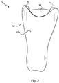
- the protection according to the invention shown in fig. 2 and 3 which is a protection 10 for footballers, displaying a stiff protective plate 12 with a shape which is adapted to the body part, in this case the user's shinbone.
- the protective plate 12 displays an outer surface 12a, which, when the protection is in use is turned away from the user and an inner surface 12b which is facing the user.
- the leg protection 10 displays shock absorbing elements in the shape of strips 14, which runs along the periphery of the inner surface of the protective plate 12b along the side edges 12 of the protective plate.
- the strips 14 are fixated to the protective plate with glue only on the far edges of the protective plate.
- a cushion 16, which can be of the same material as the strips 14 is arranged by the upper edge of the protective plate and a corresponding cushion 18 by the lower edge of the protective plate 12.
- each cushion 16, 18 such that there is an opening between the protective plate 12 and each cushion 16, 18, wherein air can pass in and out of these openings.
- Another way is to design the strips 14 with a through-going hole 14a, see fig. 3 , which runs across the length of the strip.
- the shock absorbing strips are designed with mutual spaces along the periphery such that through let of air is enabled in these spaces.
- the protective plate is according to a preferred embodiment made from one or multiple layers of plastic reinforced by fibers, where the different layers can have different direction of the fibers.
- One example of this is shown in fig. 5 , where the directions of the fibers in different layers are mutually perpendicular.
- the fiber reinforcement compresses a first layer 20a, which runs mutually parallel in a first direction, and a second fiber layer 20b, which runs mutually parallel in a second direction substantially perpendicular to the first direction.
- the direction 0°/90° i.e. mutual fiber directions where when 0° the fiber runs strictly vertical and by 90° the fiber runs strictly horizontal.
- This makes the protective plate stiff horizontally and vertically, but rotatable in directions there between for improving the fitting against the leg.
- Fiber directions foremost in directions ⁇ 45° in relation to horizontal and vertical, are for obtaining the correct stiffness in the rotational axis.
- it is preferable to use carbon fiber and/or aramide fiber for obtaining a stiff but yet light protective plate
- a protective plate which substantially does not deform at a shock against the protective plate.
- the force from the shock is distributed over the protective plate and is instead concentrated to the shock or energy absorbing elements in shape of the strips 14, which absorbs the main part of the force, instead of propagating the force into the underlying body part, in this case the bone/heel.
- the energy absorbing strips 14 are preferably made of an elastic material, such as energy absorbing rubber or an "air cushion strip", and is shaped such that they in their unloaded state gives as small contact surface as possible against the underlying body part. When a force is exerted on the protective plate the strips will deform, whereby the contacting surface increases.
- the protection 10 is preferably held in place by means of an elastic textile 22, which also functions as a user's sock, see fig. 6 .
- an elastic textile 22 which also functions as a user's sock, see fig. 6 .
- the two strips 14 and the cushions 16, 18 have been replaced by a single strip 114 which runs along the entire periphery of the protective plate 12.
- the single strip is designed with through-going ventilation holes 114a.
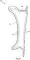
- An alternative to designing the shock absorbing elements as one or more strips is to arrange the elements as preferably circular peaks 214, which are placed with mutual spaces on the inner surface of the protective plate along the periphery of the protective plate, see fig. 8 .
- shock absorbing elements designed as peaks and valleys, wherein only the peaks are contacting the user's body in the normal state. At a shock will however all of the shock absorbing elements 214 absorb and distribute the force from the shock through that then even the valleys will come in contact with the body of the user. If the spaces between the peaks 214 are the only ventilation, there will be a shock absorbing air cushion as soon as the valleys also come into contact with the body of the user, wherein they seal against the body.
- the protective plate 12 shows through-going holes for draining of condensate from the space between the protective plate and the user's body.
- the protective plate shows a multiplicity of small through-going holes 12c, which in this embodiment are arranged in rows and columns. This multiplicity of small holes, which preferably can have a diameter of 0,5 - 1,5 millimeter, let the formed condensate out.
- Ventilation holes are shown in fig. 10 , where the protective plate 12 displays less, in the shown example two, but larger through-going ventilation holes 12c.
- the through-going holes can preferably have a diameter of 5 - 15 millimeter.
- a leg protection that protects the user's shinbone has been described.
- the protective plate has a size and shape adapted to be placed on the rear side of the user's leg such that the protective plate 12 covers the user's Achilles tendon. Whereby a protection is achieved, which protects for example football players against the commonly occurring injuries that arises with kicks from the rear.
- the embodiment shown in fig. 11 can preferably be combined with any of the above described leg protections which protects the shin bone.
- the protection comprises a protective plate which has a size and shape that is adapted for placing on the rear side of the user's leg such that the protective plate 12 covers the user's Achilles tendon, and a protective plate that has a size and shape adapted for placing on the front of the user's leg such that the protective plate covers the user's shinbone.
- the two protective plates can be kept together by e.g. means of straps.
Landscapes
- Health & Medical Sciences (AREA)
- General Health & Medical Sciences (AREA)
- Physical Education & Sports Medicine (AREA)
- Engineering & Computer Science (AREA)
- Textile Engineering (AREA)
- Professional, Industrial, Or Sporting Protective Garments (AREA)
- Aiming, Guidance, Guns With A Light Source, Armor, Camouflage, And Targets (AREA)
Description
- The present invention relates to protection generally for persons and particularly leg protection for sporting persons, such as football players.
- In many sports, such as football, the contestants should, to prevent injuries, wear protection for the body parts that otherwise is easily injured. In for example football leg protection is an example of such a protection. Other sports where leg protection is being used is handball, field hockey, downhill skiing and protection is also used in trotting. Such protection should have multiple properties. They must be able to absorb strokes an shocks without the underlying body part getting injured. Furthermore they must remain in place in a reliable way, even during the practicing of physical activities.
- Example of known protection, of which
fig. 1 shows a cross sectional view through a leg protection for footballers, displaying a deformableprotective plate 2, which is shaped after the underlying body part, in this case theleg 4 of a user. This protective plate shall protect against for example strokes and shocks from for example studs of football shoes. Since the protective plate is deformable it is deformed when hit by a kick or another stroke. For preventing that shocks and strokes continues to the underlying body part a sawn oncontact layer 6 of a soft material, such as plastic foam, is present on the surface of the protective plate which is facing the body. This contact layer is in use in direct contact with the user's skin. For keeping the protection in place, fastening arrangements 8, such as straps etc., are attached to the protective plate or the contacting layer. - Such known protection has multiple disadvantages. Of these can be mentioned that they are experienced as bulky and heavy, the extend from the leg further which can lead to bad ball handling, due to their higher weight they consume more energy of the user during training or match. Furthermore, they are poorly ventilated, which can lead to irritated skin and skin problems in the long run, such as eczema and bacterial wounds. Ventilation holes in the protection inevitably leads to weakening of the deformable protective plate. Furthermore, the soft material makes the protective plate move around and has a hard time staying properly in place. Due to that the protective plate is deformable it distributes the force of the incoming shock relatively bad and the protection may also rub against the leg.
GB 671 022 A WO 2006/092551 A1 ,EP 1 177 732 A2 ,FR 2 809 597 A3US 1 607 032 A , andUS 4 766 614 A disclose different types of protections. - A purpose of the present invention is hence to achieve a protection of the prior mentioned kind, by which the above stated problems with the prior art is avoided or at least minimized.
- The invention is based on the understanding that the contacting surface towards the underlying skin can be minimized through a protection for a body part of a person being designed with a stiff protective plate, which as such do not absorb any shocks, and one or more shock absorbing elements arranged along the periphery of the protective plate on the side facing the body part.
- With the protection according to the invention many advantages are achieved. A very well ventilated protection is obtained which further can be manufactured with very low weight. The protective property is good and conventional fastening can be left out due to considerably lower weight and in relation more friction on contacting shock absorbing elements, which simplifies the use.
- Through designing the protective plate from one or more layers of plastic reinforced with fibers, such as carbon fiber reinforced plastic or aramide fiber reinforced plastic, a light but still stiff construction is achieved.
- The protection can be provided with ventilation holes in the shock absorbing elements or in the protective plate for draining condensation. Further embodiments are defined by the dependent claims.
- The invention will now be described in embodiments, with reference to the enclosed drawings, in which:
-
fig. 1 is a cross section through a protection in accordance with the prior art, -
fig. 2 is a perspective view of the front of a protection in accordance with the invention, -
fig. 3 is a perspective view of the rear of the protection infig. 2 , -
fig. 4 is a cross section through the protection displayed infig. 2 and3 , -
fig. 5 shows a detailed view of the reinforcement of a protective plate which is part of a protection according to the present invention, -
fig. 6 shows a textile for keeping the protection in place, -
fig. 7 shows an alternative embodiment of a protection according to the invention, -
fig. 8 shows yet another alternative example of a protection which is not part of the invention, -
fig. 9 shows the front of a protection according to the invention, of which the placing of the ventilation holes is shown, -
fig. 10 shows an alternative embodiment of ventilation holes, and -
fig. 11 shows an alternative embodiment being a heel protection. - In the following a detailed description of preferred embodiments will be given. It shall be noted that direction presented in the description, such as "horizontal" and "vertical" only refers to what is shown in the figures and shall not in any way be considered limiting apart from that.
- The protection according to the invention shown in
fig. 2 and3 , which is aprotection 10 for footballers, displaying a stiffprotective plate 12 with a shape which is adapted to the body part, in this case the user's shinbone. Theprotective plate 12 displays anouter surface 12a, which, when the protection is in use is turned away from the user and aninner surface 12b which is facing the user. Furthermore, seefig. 3 , theleg protection 10 displays shock absorbing elements in the shape ofstrips 14, which runs along the periphery of the inner surface of theprotective plate 12b along theside edges 12 of the protective plate. Preferably thestrips 14 are fixated to the protective plate with glue only on the far edges of the protective plate. Acushion 16, which can be of the same material as thestrips 14 is arranged by the upper edge of the protective plate and acorresponding cushion 18 by the lower edge of theprotective plate 12. - The placing of the
strips 14 appears evidently in the cross section view offig. 4 . It is here seen that a space is created between theprotective plate 12 and thebone 4, whereby a large contacting surface is avoided, which can lead to the above mentioned problems with skin irritations etc. The ventilation of this space can be improved in multiple ways. One way is to arrange eachcushion protective plate 12 and eachcushion strips 14 with a through-going hole 14a, seefig. 3 , which runs across the length of the strip. An alternative to this is that the shock absorbing strips are designed with mutual spaces along the periphery such that through let of air is enabled in these spaces. - The protective plate is according to a preferred embodiment made from one or multiple layers of plastic reinforced by fibers, where the different layers can have different direction of the fibers. One example of this is shown in
fig. 5 , where the directions of the fibers in different layers are mutually perpendicular. Hence the fiber reinforcement compresses afirst layer 20a, which runs mutually parallel in a first direction, and asecond fiber layer 20b, which runs mutually parallel in a second direction substantially perpendicular to the first direction. Thedirection 0°/90°, i.e. mutual fiber directions where when 0° the fiber runs strictly vertical and by 90° the fiber runs strictly horizontal. This makes the protective plate stiff horizontally and vertically, but rotatable in directions there between for improving the fitting against the leg. Fiber directions, foremost in directions ±45° in relation to horizontal and vertical, are for obtaining the correct stiffness in the rotational axis. For example it is preferable to use carbon fiber and/or aramide fiber for obtaining a stiff but yet lightprotective plate 12. - Through this reinforcement a protective plate is obtained which substantially does not deform at a shock against the protective plate. The force from the shock is distributed over the protective plate and is instead concentrated to the shock or energy absorbing elements in shape of the
strips 14, which absorbs the main part of the force, instead of propagating the force into the underlying body part, in this case the bone/heel. Theenergy absorbing strips 14 are preferably made of an elastic material, such as energy absorbing rubber or an "air cushion strip", and is shaped such that they in their unloaded state gives as small contact surface as possible against the underlying body part. When a force is exerted on the protective plate the strips will deform, whereby the contacting surface increases. Thereby the friction between thestrips 14 and the underlying skin is increased, which contributes to keeping the protection in place, whereby you do not need any extra fastening arrangements, such as straps. The remaining force from the impact which has not been absorbed by thestrip 14 will thereafter reach the skin, whereafter it propagates into the bone. - The
protection 10 is preferably held in place by means of anelastic textile 22, which also functions as a user's sock, seefig. 6 .
In an alternative embodiment, which is shown infig. 7 , the twostrips 14 and thecushions single strip 114 which runs along the entire periphery of theprotective plate 12. Just as in the embodiment described above with reference tofig. 3 the single strip is designed with through-goingventilation holes 114a.
An alternative to designing the shock absorbing elements as one or more strips is to arrange the elements as preferablycircular peaks 214, which are placed with mutual spaces on the inner surface of the protective plate along the periphery of the protective plate, seefig. 8 . With other words is the shock absorbing elements designed as peaks and valleys, wherein only the peaks are contacting the user's body in the normal state. At a shock will however all of theshock absorbing elements 214 absorb and distribute the force from the shock through that then even the valleys will come in contact with the body of the user. If the spaces between thepeaks 214 are the only ventilation, there will be a shock absorbing air cushion as soon as the valleys also come into contact with the body of the user, wherein they seal against the body. - A complement to designing the shock absorbing element with ventilation holes is that the
protective plate 12 shows through-going holes for draining of condensate from the space between the protective plate and the user's body. Infig. 9 , which shows the front 12a of theprotective plate 12 on aleg protection 10, it is seen that the protective plate shows a multiplicity of small through-goingholes 12c, which in this embodiment are arranged in rows and columns. This multiplicity of small holes, which preferably can have a diameter of 0,5 - 1,5 millimeter, let the formed condensate out. - An alternative design of ventilation holes is shown in
fig. 10 , where theprotective plate 12 displays less, in the shown example two, but larger through-goingventilation holes 12c. In this case the through-going holes can preferably have a diameter of 5 - 15 millimeter. A leg protection that protects the user's shinbone has been described. In an alternative embodiment, which is shown infig. 11 , the protective plate has a size and shape adapted to be placed on the rear side of the user's leg such that theprotective plate 12 covers the user's Achilles tendon. Whereby a protection is achieved, which protects for example football players against the commonly occurring injuries that arises with kicks from the rear. - The embodiment shown in
fig. 11 can preferably be combined with any of the above described leg protections which protects the shin bone. Hence the protection comprises a protective plate which has a size and shape that is adapted for placing on the rear side of the user's leg such that theprotective plate 12 covers the user's Achilles tendon, and a protective plate that has a size and shape adapted for placing on the front of the user's leg such that the protective plate covers the user's shinbone. In this case, the two protective plates can be kept together by e.g. means of straps. - Preferred embodiments of a protection according to the invention have been described. It is understood that the invention can be altered within the scope of appended claims. Hence a protection for football players has been described. It is understood that the principle according to the invention with a stiff protective plate and a shock absorbing strip arranged along the periphery of the protective plate can be applied on upper and lower arms and other sports such as handball, field hockey, downhill skiing, motorcycle sports, trotting (horse leg protection), rugby, American football and cricket.
- The described different ways of ventilating the space between the
protective plate 12 and the body of theuser 4 can be used separately or in optional combinations. It is also conceivable to exclude the ventilation. It is also understood, that the different embodiments of shock absorbing elements can be mixed in one embodiment. For example one could alternate between distances of strips, such as shown infig. 3 , and distances of peaks, as shown infig. 8 . The scope of the invention is defined in the appended claims.
Claims (12)
- A protection for a leg or an upper and lower arm of a user, comprising a stiff protective plate (12) with a shape adapted to the leg or upper or lower arm, which protective plate displays an outer surface (12a) arranged to be turned away from the user and an inner surface (12b) arranged to be facing the user, and at least one shock absorbing element (14; 114; 214) arranged on the inner surface along the periphery of the protective plate, wherein said at least one shock absorbing element comprises at least one strip (14), characterized in that said at least one strip (14) displays peaks or cones with mutual spaces or displays through-going holes (14a).
- Protection according to claim 1, wherein said at least one shock absorbing element (14; 114; 214) is made from an elastic material.
- Protection according to any one of claims 1 - 2, wherein the protective plate (12) is built up by at least one layer fiber reinforced plastic.
- Protection according to claim 3, wherein the protective plate (12) is built up of multiple layers of fiber reinforced plastic with different fiber directions.
- Protection according to claim 3 or 4, wherein the protective plate (12) comprises any of the following fiber materials: carbon fiber and aramide fiber.
- Protection according to any one of claims 1 - 5, wherein the protective plate (12) displays through-going holes (12c).
- Protection according to claim 6, wherein the through-going holes (12c) have a diameter of 0,5 - 1,5 millimeter.
- Protection according to claim 6, wherein the through-going holes (12c) have a diameter of 5 - 15 millimeter.
- Protection according to any one of claims 1 - 8, wherein the protective plate (12) has a size and shape adapted for placing on the rear side of the user's leg such that the protective plate covers the user's Achilles tendon.
- Protection according to claim 1, comprising a first protective plate having a size and shape adapted for placing on the rear side of the user's leg such that the first protective plate covers the user's Achilles tendon, and a second protective plate having a size and shape adapted for placing on the front of the user's leg such that the second protective plate covers the user's shinbone.
- Protection according to any one of claims 1 - 10, wherein said at least one shock absorbing element comprises rubber.
- Use of a protection according to claim 1, as sports protection.
Applications Claiming Priority (2)
| Application Number | Priority Date | Filing Date | Title |
|---|---|---|---|
| SE0800334A SE532791C2 (en) | 2008-02-14 | 2008-02-14 | Protection for a body part of a user |
| PCT/SE2009/050122 WO2009102268A1 (en) | 2008-02-14 | 2009-02-06 | Protective gear |
Publications (3)
| Publication Number | Publication Date |
|---|---|
| EP2242547A1 EP2242547A1 (en) | 2010-10-27 |
| EP2242547A4 EP2242547A4 (en) | 2013-01-23 |
| EP2242547B1 true EP2242547B1 (en) | 2018-12-19 |
Family
ID=40957175
Family Applications (1)
| Application Number | Title | Priority Date | Filing Date |
|---|---|---|---|
| EP09711322.9A Active EP2242547B1 (en) | 2008-02-14 | 2009-02-06 | Protective gear |
Country Status (5)
| Country | Link |
|---|---|
| US (1) | US8769715B2 (en) |
| EP (1) | EP2242547B1 (en) |
| ES (1) | ES2716475T3 (en) |
| SE (1) | SE532791C2 (en) |
| WO (1) | WO2009102268A1 (en) |
Families Citing this family (8)
| Publication number | Priority date | Publication date | Assignee | Title |
|---|---|---|---|---|
| US10159295B2 (en) | 2012-03-08 | 2018-12-25 | Nike, Inc. | Protective pad using a damping component |
| US10206437B2 (en) | 2012-03-08 | 2019-02-19 | Nike, Inc. | Protective pad using a damping component |
| US20140068831A1 (en) * | 2012-09-13 | 2014-03-13 | Michael Tinsley | Shin Protection Device |
| US10709179B2 (en) * | 2013-03-14 | 2020-07-14 | Nike, Inc. | Protective apparatus having an impact attenuation component |
| EP2967161B1 (en) * | 2013-03-15 | 2019-05-15 | NIKE Innovate C.V. | Protective pad using a damping component |
| SG10201405289XA (en) * | 2013-08-27 | 2015-03-30 | Agency Science Tech & Res | A composite foam laminate and its usage |
| US20180214764A1 (en) * | 2015-07-15 | 2018-08-02 | Global Flow S.L. | Shin protection element and protection assembly for cyclists |
| US20240157223A1 (en) * | 2022-10-17 | 2024-05-16 | Robert Ray Blocker | Apparatus for medially thickened shin pad to reduce lower leg discomfort when snow skiing |
Citations (1)
| Publication number | Priority date | Publication date | Assignee | Title |
|---|---|---|---|---|
| US5405312A (en) * | 1992-06-22 | 1995-04-11 | Safe-T-Gard Corporation | Custom fit body guards |
Family Cites Families (39)
| Publication number | Priority date | Publication date | Assignee | Title |
|---|---|---|---|---|
| US833546A (en) * | 1906-03-07 | 1906-10-16 | George L Pierce | Body-protector. |
| US1253260A (en) * | 1917-03-06 | 1918-01-15 | David Levinson | Protecting pad or armor. |
| US1428731A (en) * | 1921-07-11 | 1922-09-12 | Rawlings Mfg Co | Thigh guard |
| US1607032A (en) * | 1925-01-07 | 1926-11-16 | Rawlings Mfg Co | Thigh guard |
| US1688676A (en) * | 1925-12-28 | 1928-10-23 | Rawlings Mfg Co | Athletic guard |
| US1784148A (en) * | 1929-03-23 | 1930-12-09 | Wilson Western Sporting Goods | Guard for athletes |
| US1812579A (en) * | 1929-12-02 | 1931-06-30 | Rawlings Mfg Co | Athletic guard |
| US2553612A (en) * | 1948-11-15 | 1951-05-22 | James P Taylor | Self-grip waterproof blow distributing shin guard |
| US2544065A (en) * | 1949-04-29 | 1951-03-06 | Richard E Carr | Stocking attachment |
| GB671022A (en) * | 1950-09-29 | 1952-04-30 | James Philip Taylor | Improvements in or relating to shin guards |
| US2818571A (en) * | 1955-03-24 | 1958-01-07 | Munro M Grant | Thigh pads for use in contact sports equipment |
| US3585639A (en) * | 1969-02-24 | 1971-06-22 | Johnson & Johnson | Protective athletic pad |
| US3877077A (en) * | 1973-11-23 | 1975-04-15 | Mylec Inc | Goaltender{3 s protective plastic pads |
| US4001953A (en) * | 1974-04-15 | 1977-01-11 | Albert Lee Fugere | Protective gaiter |
| USD280145S (en) * | 1982-08-17 | 1985-08-20 | Sports Marketing, Inc. | Thigh protector |
| FR2600900B1 (en) * | 1986-04-16 | 1991-05-17 | Commissariat Energie Atomique | DEVICE FOR PROTECTING AND / OR HOLDING A PART OF A HUMAN OR ANIMAL BODY, PARTICULARLY THE LEGS OF A FOOTBALL PLAYER, AND METHOD FOR PRODUCING SUCH A DEVICE |
| EP0254751B1 (en) * | 1986-07-25 | 1989-12-06 | Descente Ltd. | Protector for sportswear |
| US4766614A (en) * | 1986-12-31 | 1988-08-30 | Cantwell Jay S | Ventilated protective headgear |
| US5093931A (en) * | 1989-07-20 | 1992-03-10 | Sport Maska Inc. | Protective equipment having a rebound controlling insert |
| US5007111A (en) * | 1989-09-14 | 1991-04-16 | Adams Mark B | Shock absorbing boot and cushioning material |
| DE9307949U1 (en) * | 1993-05-26 | 1993-09-16 | Finsterseifer, Axel, 56357 Miehlen | Protection against injury for athletes, especially for lower legs |
| CA2141374A1 (en) * | 1995-01-30 | 1996-07-31 | Vince Dicesare | Goalie pad covers |
| US5544663A (en) * | 1995-07-20 | 1996-08-13 | Parker Medical Associates | Front-to-back and side-to-side custom-molded protective device |
| US6065152A (en) * | 1996-04-19 | 2000-05-23 | Adidas-Salomon Ag | Athletic shin guard |
| AUPO760397A0 (en) * | 1997-06-27 | 1997-07-24 | Byrne, Patrick Joseph | A protector pad |
| GB2352208B (en) * | 1999-07-13 | 2001-06-13 | Stirling Moulded Composites Lt | Flexible material |
| US6681403B2 (en) * | 2000-03-13 | 2004-01-27 | Robert M. Lyden | Shin-guard, helmet, and articles of protective equipment including light cure material |
| ITTV20000062A1 (en) * | 2000-05-30 | 2001-11-30 | Benetton Spa | PROTECTIVE STRUCTURE PARTICULARLY FOR SPORTS USE |
| US6178556B1 (en) * | 2000-07-17 | 2001-01-30 | Parker Athletic Products, Llc | Custom-fitted catcher's leg guard and method |
| EP1177732A3 (en) * | 2000-08-04 | 2004-03-10 | Georg Dr. Ahlbäumer | Inline skate or working protector for knee or elbow |
| CA2337566C (en) * | 2001-02-20 | 2007-03-27 | Chris Budda | Body guard |
| KR200265810Y1 (en) * | 2001-11-14 | 2002-02-25 | 김휘 | leg guards |
| US20040094915A1 (en) * | 2002-11-20 | 2004-05-20 | Warren Wesley H | Rolling kneepad caster device |
| US7757310B2 (en) * | 2004-01-12 | 2010-07-20 | Shock Doctor, Inc. | Impact protection device |
| US7503080B2 (en) * | 2004-05-12 | 2009-03-17 | Tufts Medical Center, Inc. | Chest wall protector |
| DE102004040793B4 (en) * | 2004-08-23 | 2014-06-05 | Bauerfeind Ag | Elastic knee joint bandage |
| GB0504316D0 (en) * | 2005-03-02 | 2005-04-06 | Coates Nicholas R | Protective clothing |
| WO2007064995A2 (en) * | 2005-12-02 | 2007-06-07 | Dan Lueking | Apparatus and methods for holding shin guards in position |
| US7937768B2 (en) * | 2007-10-18 | 2011-05-10 | Nike, Inc. | Flexible shin guard |
-
2008
- 2008-02-14 SE SE0800334A patent/SE532791C2/en unknown
-
2009
- 2009-02-06 ES ES09711322T patent/ES2716475T3/en active Active
- 2009-02-06 WO PCT/SE2009/050122 patent/WO2009102268A1/en not_active Ceased
- 2009-02-06 EP EP09711322.9A patent/EP2242547B1/en active Active
- 2009-02-08 US US12/867,642 patent/US8769715B2/en active Active
Patent Citations (1)
| Publication number | Priority date | Publication date | Assignee | Title |
|---|---|---|---|---|
| US5405312A (en) * | 1992-06-22 | 1995-04-11 | Safe-T-Gard Corporation | Custom fit body guards |
Also Published As
| Publication number | Publication date |
|---|---|
| WO2009102268A1 (en) | 2009-08-20 |
| US20110041227A1 (en) | 2011-02-24 |
| SE532791C2 (en) | 2010-04-13 |
| EP2242547A4 (en) | 2013-01-23 |
| US8769715B2 (en) | 2014-07-08 |
| ES2716475T3 (en) | 2019-06-12 |
| EP2242547A1 (en) | 2010-10-27 |
| SE0800334L (en) | 2009-08-15 |
Similar Documents
| Publication | Publication Date | Title |
|---|---|---|
| US8769715B2 (en) | Protective gear | |
| US7937768B2 (en) | Flexible shin guard | |
| JP5749182B2 (en) | Energy absorption and displacement structure for sports protective equipment | |
| US10021919B2 (en) | Method and device for protecting the human body from foot strike shock | |
| JP5976095B2 (en) | Sole used for footwear and method of forming the same | |
| US8875319B2 (en) | Protective element for use in sport | |
| US9266007B2 (en) | Goalie skate | |
| CA2772503A1 (en) | Protective sports equipment and methods of making same | |
| US20080252061A1 (en) | Armouring/reinforcing applications associated with a sports skate or shoe | |
| CN102349726B (en) | Shock-proof sprain-preventing sole | |
| US20140359913A1 (en) | Protective Ice Hockey Sock | |
| US20170144053A1 (en) | Vented shin guard | |
| US9867407B1 (en) | Impact-resistant padding | |
| EP1976602B1 (en) | Anatomical forearm protection. | |
| US9802104B2 (en) | Reticulated digit shield for protective sports glove | |
| KR100943088B1 (en) | Insoles for sports shoes using fiber-reinforced plastics | |
| US9609906B2 (en) | Hockey skate shield | |
| CN100534555C (en) | Protective element for body parts | |
| CN102396840A (en) | Shock-absorbing torsion-resistant element for sole | |
| WO2013150472A1 (en) | An impact energy management system, sports apparel and methods thereof | |
| JPH0116403Y2 (en) | ||
| KR200414510Y1 (en) | Grappling Footguards | |
| KR101887302B1 (en) | Support for snow boarding | |
| CN223874390U (en) | A chainmail-structured protective gear and sports protective gear | |
| SK50122013U1 (en) | Vamp protector |
Legal Events
| Date | Code | Title | Description |
|---|---|---|---|
| PUAI | Public reference made under article 153(3) epc to a published international application that has entered the european phase |
Free format text: ORIGINAL CODE: 0009012 |
|
| 17P | Request for examination filed |
Effective date: 20100729 |
|
| AK | Designated contracting states |
Kind code of ref document: A1 Designated state(s): AT BE BG CH CY CZ DE DK EE ES FI FR GB GR HR HU IE IS IT LI LT LU LV MC MK MT NL NO PL PT RO SE SI SK TR |
|
| AX | Request for extension of the european patent |
Extension state: AL BA RS |
|
| DAX | Request for extension of the european patent (deleted) | ||
| A4 | Supplementary search report drawn up and despatched |
Effective date: 20130103 |
|
| RIC1 | Information provided on ipc code assigned before grant |
Ipc: A63B 71/12 20060101ALI20121219BHEP Ipc: A63B 71/08 20060101AFI20121219BHEP Ipc: A41D 13/06 20060101ALI20121219BHEP Ipc: A41D 13/05 20060101ALI20121219BHEP |
|
| STAA | Information on the status of an ep patent application or granted ep patent |
Free format text: STATUS: EXAMINATION IS IN PROGRESS |
|
| 17Q | First examination report despatched |
Effective date: 20161123 |
|
| REG | Reference to a national code |
Ref country code: DE Ref legal event code: R079 Ref document number: 602009056263 Country of ref document: DE Free format text: PREVIOUS MAIN CLASS: A63B0071080000 Ipc: A63B0102200000 |
|
| RIC1 | Information provided on ipc code assigned before grant |
Ipc: A63B 102/22 20150101ALI20171207BHEP Ipc: A63B 71/12 20060101ALI20171207BHEP Ipc: A63B 102/20 20150101AFI20171207BHEP |
|
| GRAP | Despatch of communication of intention to grant a patent |
Free format text: ORIGINAL CODE: EPIDOSNIGR1 |
|
| STAA | Information on the status of an ep patent application or granted ep patent |
Free format text: STATUS: GRANT OF PATENT IS INTENDED |
|
| INTG | Intention to grant announced |
Effective date: 20180206 |
|
| GRAJ | Information related to disapproval of communication of intention to grant by the applicant or resumption of examination proceedings by the epo deleted |
Free format text: ORIGINAL CODE: EPIDOSDIGR1 |
|
| STAA | Information on the status of an ep patent application or granted ep patent |
Free format text: STATUS: EXAMINATION IS IN PROGRESS |
|
| INTC | Intention to grant announced (deleted) | ||
| GRAP | Despatch of communication of intention to grant a patent |
Free format text: ORIGINAL CODE: EPIDOSNIGR1 |
|
| STAA | Information on the status of an ep patent application or granted ep patent |
Free format text: STATUS: GRANT OF PATENT IS INTENDED |
|
| INTG | Intention to grant announced |
Effective date: 20180726 |
|
| GRAS | Grant fee paid |
Free format text: ORIGINAL CODE: EPIDOSNIGR3 |
|
| GRAA | (expected) grant |
Free format text: ORIGINAL CODE: 0009210 |
|
| STAA | Information on the status of an ep patent application or granted ep patent |
Free format text: STATUS: THE PATENT HAS BEEN GRANTED |
|
| AK | Designated contracting states |
Kind code of ref document: B1 Designated state(s): AT BE BG CH CY CZ DE DK EE ES FI FR GB GR HR HU IE IS IT LI LT LU LV MC MK MT NL NO PL PT RO SE SI SK TR |
|
| REG | Reference to a national code |
Ref country code: GB Ref legal event code: FG4D |
|
| REG | Reference to a national code |
Ref country code: CH Ref legal event code: EP |
|
| REG | Reference to a national code |
Ref country code: IE Ref legal event code: FG4D |
|
| REG | Reference to a national code |
Ref country code: DE Ref legal event code: R096 Ref document number: 602009056263 Country of ref document: DE |
|
| REG | Reference to a national code |
Ref country code: AT Ref legal event code: REF Ref document number: 1078059 Country of ref document: AT Kind code of ref document: T Effective date: 20190115 |
|
| REG | Reference to a national code |
Ref country code: CH Ref legal event code: PK Free format text: BERICHTIGUNGEN |
|
| RIC2 | Information provided on ipc code assigned after grant |
Ipc: A63B 102/22 20150101ALI20171207BHEP Ipc: A63B 102/20 20150101AFI20171207BHEP Ipc: A63B 71/12 20060101ALI20171207BHEP |
|
| REG | Reference to a national code |
Ref country code: NL Ref legal event code: MP Effective date: 20181219 |
|
| PG25 | Lapsed in a contracting state [announced via postgrant information from national office to epo] |
Ref country code: LV Free format text: LAPSE BECAUSE OF FAILURE TO SUBMIT A TRANSLATION OF THE DESCRIPTION OR TO PAY THE FEE WITHIN THE PRESCRIBED TIME-LIMIT Effective date: 20181219 Ref country code: BG Free format text: LAPSE BECAUSE OF FAILURE TO SUBMIT A TRANSLATION OF THE DESCRIPTION OR TO PAY THE FEE WITHIN THE PRESCRIBED TIME-LIMIT Effective date: 20190319 Ref country code: LT Free format text: LAPSE BECAUSE OF FAILURE TO SUBMIT A TRANSLATION OF THE DESCRIPTION OR TO PAY THE FEE WITHIN THE PRESCRIBED TIME-LIMIT Effective date: 20181219 Ref country code: HR Free format text: LAPSE BECAUSE OF FAILURE TO SUBMIT A TRANSLATION OF THE DESCRIPTION OR TO PAY THE FEE WITHIN THE PRESCRIBED TIME-LIMIT Effective date: 20181219 Ref country code: FI Free format text: LAPSE BECAUSE OF FAILURE TO SUBMIT A TRANSLATION OF THE DESCRIPTION OR TO PAY THE FEE WITHIN THE PRESCRIBED TIME-LIMIT Effective date: 20181219 Ref country code: NO Free format text: LAPSE BECAUSE OF FAILURE TO SUBMIT A TRANSLATION OF THE DESCRIPTION OR TO PAY THE FEE WITHIN THE PRESCRIBED TIME-LIMIT Effective date: 20190319 |
|
| REG | Reference to a national code |
Ref country code: LT Ref legal event code: MG4D |
|
| REG | Reference to a national code |
Ref country code: AT Ref legal event code: MK05 Ref document number: 1078059 Country of ref document: AT Kind code of ref document: T Effective date: 20181219 |
|
| PG25 | Lapsed in a contracting state [announced via postgrant information from national office to epo] |
Ref country code: SE Free format text: LAPSE BECAUSE OF FAILURE TO SUBMIT A TRANSLATION OF THE DESCRIPTION OR TO PAY THE FEE WITHIN THE PRESCRIBED TIME-LIMIT Effective date: 20181219 Ref country code: GR Free format text: LAPSE BECAUSE OF FAILURE TO SUBMIT A TRANSLATION OF THE DESCRIPTION OR TO PAY THE FEE WITHIN THE PRESCRIBED TIME-LIMIT Effective date: 20190320 |
|
| REG | Reference to a national code |
Ref country code: ES Ref legal event code: FG2A Ref document number: 2716475 Country of ref document: ES Kind code of ref document: T3 Effective date: 20190612 |
|
| PG25 | Lapsed in a contracting state [announced via postgrant information from national office to epo] |
Ref country code: NL Free format text: LAPSE BECAUSE OF FAILURE TO SUBMIT A TRANSLATION OF THE DESCRIPTION OR TO PAY THE FEE WITHIN THE PRESCRIBED TIME-LIMIT Effective date: 20181219 |
|
| PG25 | Lapsed in a contracting state [announced via postgrant information from national office to epo] |
Ref country code: PT Free format text: LAPSE BECAUSE OF FAILURE TO SUBMIT A TRANSLATION OF THE DESCRIPTION OR TO PAY THE FEE WITHIN THE PRESCRIBED TIME-LIMIT Effective date: 20190419 Ref country code: CZ Free format text: LAPSE BECAUSE OF FAILURE TO SUBMIT A TRANSLATION OF THE DESCRIPTION OR TO PAY THE FEE WITHIN THE PRESCRIBED TIME-LIMIT Effective date: 20181219 Ref country code: PL Free format text: LAPSE BECAUSE OF FAILURE TO SUBMIT A TRANSLATION OF THE DESCRIPTION OR TO PAY THE FEE WITHIN THE PRESCRIBED TIME-LIMIT Effective date: 20181219 |
|
| PG25 | Lapsed in a contracting state [announced via postgrant information from national office to epo] |
Ref country code: RO Free format text: LAPSE BECAUSE OF FAILURE TO SUBMIT A TRANSLATION OF THE DESCRIPTION OR TO PAY THE FEE WITHIN THE PRESCRIBED TIME-LIMIT Effective date: 20181219 Ref country code: SK Free format text: LAPSE BECAUSE OF FAILURE TO SUBMIT A TRANSLATION OF THE DESCRIPTION OR TO PAY THE FEE WITHIN THE PRESCRIBED TIME-LIMIT Effective date: 20181219 Ref country code: IS Free format text: LAPSE BECAUSE OF FAILURE TO SUBMIT A TRANSLATION OF THE DESCRIPTION OR TO PAY THE FEE WITHIN THE PRESCRIBED TIME-LIMIT Effective date: 20190419 Ref country code: EE Free format text: LAPSE BECAUSE OF FAILURE TO SUBMIT A TRANSLATION OF THE DESCRIPTION OR TO PAY THE FEE WITHIN THE PRESCRIBED TIME-LIMIT Effective date: 20181219 |
|
| REG | Reference to a national code |
Ref country code: DE Ref legal event code: R097 Ref document number: 602009056263 Country of ref document: DE |
|
| REG | Reference to a national code |
Ref country code: CH Ref legal event code: PL |
|
| PLBE | No opposition filed within time limit |
Free format text: ORIGINAL CODE: 0009261 |
|
| STAA | Information on the status of an ep patent application or granted ep patent |
Free format text: STATUS: NO OPPOSITION FILED WITHIN TIME LIMIT |
|
| PG25 | Lapsed in a contracting state [announced via postgrant information from national office to epo] |
Ref country code: AT Free format text: LAPSE BECAUSE OF FAILURE TO SUBMIT A TRANSLATION OF THE DESCRIPTION OR TO PAY THE FEE WITHIN THE PRESCRIBED TIME-LIMIT Effective date: 20181219 Ref country code: LU Free format text: LAPSE BECAUSE OF NON-PAYMENT OF DUE FEES Effective date: 20190206 Ref country code: DK Free format text: LAPSE BECAUSE OF FAILURE TO SUBMIT A TRANSLATION OF THE DESCRIPTION OR TO PAY THE FEE WITHIN THE PRESCRIBED TIME-LIMIT Effective date: 20181219 Ref country code: MC Free format text: LAPSE BECAUSE OF FAILURE TO SUBMIT A TRANSLATION OF THE DESCRIPTION OR TO PAY THE FEE WITHIN THE PRESCRIBED TIME-LIMIT Effective date: 20181219 |
|
| REG | Reference to a national code |
Ref country code: BE Ref legal event code: MM Effective date: 20190228 |
|
| 26N | No opposition filed |
Effective date: 20190920 |
|
| REG | Reference to a national code |
Ref country code: IE Ref legal event code: MM4A |
|
| PG25 | Lapsed in a contracting state [announced via postgrant information from national office to epo] |
Ref country code: LI Free format text: LAPSE BECAUSE OF NON-PAYMENT OF DUE FEES Effective date: 20190228 Ref country code: CH Free format text: LAPSE BECAUSE OF NON-PAYMENT OF DUE FEES Effective date: 20190228 |
|
| PG25 | Lapsed in a contracting state [announced via postgrant information from national office to epo] |
Ref country code: IE Free format text: LAPSE BECAUSE OF NON-PAYMENT OF DUE FEES Effective date: 20190206 |
|
| PG25 | Lapsed in a contracting state [announced via postgrant information from national office to epo] |
Ref country code: SI Free format text: LAPSE BECAUSE OF FAILURE TO SUBMIT A TRANSLATION OF THE DESCRIPTION OR TO PAY THE FEE WITHIN THE PRESCRIBED TIME-LIMIT Effective date: 20181219 Ref country code: BE Free format text: LAPSE BECAUSE OF NON-PAYMENT OF DUE FEES Effective date: 20190228 |
|
| PG25 | Lapsed in a contracting state [announced via postgrant information from national office to epo] |
Ref country code: TR Free format text: LAPSE BECAUSE OF FAILURE TO SUBMIT A TRANSLATION OF THE DESCRIPTION OR TO PAY THE FEE WITHIN THE PRESCRIBED TIME-LIMIT Effective date: 20181219 |
|
| PG25 | Lapsed in a contracting state [announced via postgrant information from national office to epo] |
Ref country code: MT Free format text: LAPSE BECAUSE OF NON-PAYMENT OF DUE FEES Effective date: 20190206 |
|
| PG25 | Lapsed in a contracting state [announced via postgrant information from national office to epo] |
Ref country code: CY Free format text: LAPSE BECAUSE OF FAILURE TO SUBMIT A TRANSLATION OF THE DESCRIPTION OR TO PAY THE FEE WITHIN THE PRESCRIBED TIME-LIMIT Effective date: 20181219 |
|
| PG25 | Lapsed in a contracting state [announced via postgrant information from national office to epo] |
Ref country code: HU Free format text: LAPSE BECAUSE OF FAILURE TO SUBMIT A TRANSLATION OF THE DESCRIPTION OR TO PAY THE FEE WITHIN THE PRESCRIBED TIME-LIMIT; INVALID AB INITIO Effective date: 20090206 |
|
| PG25 | Lapsed in a contracting state [announced via postgrant information from national office to epo] |
Ref country code: MK Free format text: LAPSE BECAUSE OF FAILURE TO SUBMIT A TRANSLATION OF THE DESCRIPTION OR TO PAY THE FEE WITHIN THE PRESCRIBED TIME-LIMIT Effective date: 20181219 |
|
| PGFP | Annual fee paid to national office [announced via postgrant information from national office to epo] |
Ref country code: GB Payment date: 20260217 Year of fee payment: 18 |
|
| PGFP | Annual fee paid to national office [announced via postgrant information from national office to epo] |
Ref country code: ES Payment date: 20260303 Year of fee payment: 18 |
|
| PGFP | Annual fee paid to national office [announced via postgrant information from national office to epo] |
Ref country code: DE Payment date: 20260217 Year of fee payment: 18 |
|
| PGFP | Annual fee paid to national office [announced via postgrant information from national office to epo] |
Ref country code: IT Payment date: 20260223 Year of fee payment: 18 |
|
| PGFP | Annual fee paid to national office [announced via postgrant information from national office to epo] |
Ref country code: FR Payment date: 20260217 Year of fee payment: 18 |