EP2242438B1 - System for delivering moisturizing liquid to lips of a subject - Google Patents
System for delivering moisturizing liquid to lips of a subject Download PDFInfo
- Publication number
- EP2242438B1 EP2242438B1 EP09710980A EP09710980A EP2242438B1 EP 2242438 B1 EP2242438 B1 EP 2242438B1 EP 09710980 A EP09710980 A EP 09710980A EP 09710980 A EP09710980 A EP 09710980A EP 2242438 B1 EP2242438 B1 EP 2242438B1
- Authority
- EP
- European Patent Office
- Prior art keywords
- applicator
- subject
- lips
- reservoir
- liquid
- Prior art date
- Legal status (The legal status is an assumption and is not a legal conclusion. Google has not performed a legal analysis and makes no representation as to the accuracy of the status listed.)
- Active
Links
Images




Classifications
-
- A—HUMAN NECESSITIES
- A61—MEDICAL OR VETERINARY SCIENCE; HYGIENE
- A61J—CONTAINERS SPECIALLY ADAPTED FOR MEDICAL OR PHARMACEUTICAL PURPOSES; DEVICES OR METHODS SPECIALLY ADAPTED FOR BRINGING PHARMACEUTICAL PRODUCTS INTO PARTICULAR PHYSICAL OR ADMINISTERING FORMS; DEVICES FOR ADMINISTERING FOOD OR MEDICINES ORALLY; BABY COMFORTERS; DEVICES FOR RECEIVING SPITTLE
- A61J15/00—Feeding-tubes for therapeutic purposes
- A61J15/0011—Feeding-tubes for delivery of nourishment to the mouth; Mouth pieces therefor
-
- A—HUMAN NECESSITIES
- A61—MEDICAL OR VETERINARY SCIENCE; HYGIENE
- A61J—CONTAINERS SPECIALLY ADAPTED FOR MEDICAL OR PHARMACEUTICAL PURPOSES; DEVICES OR METHODS SPECIALLY ADAPTED FOR BRINGING PHARMACEUTICAL PRODUCTS INTO PARTICULAR PHYSICAL OR ADMINISTERING FORMS; DEVICES FOR ADMINISTERING FOOD OR MEDICINES ORALLY; BABY COMFORTERS; DEVICES FOR RECEIVING SPITTLE
- A61J15/00—Feeding-tubes for therapeutic purposes
- A61J15/0026—Parts, details or accessories for feeding-tubes
- A61J15/0053—Means for fixing the tube outside of the body, e.g. by a special shape, by fixing it to the skin
-
- A—HUMAN NECESSITIES
- A61—MEDICAL OR VETERINARY SCIENCE; HYGIENE
- A61J—CONTAINERS SPECIALLY ADAPTED FOR MEDICAL OR PHARMACEUTICAL PURPOSES; DEVICES OR METHODS SPECIALLY ADAPTED FOR BRINGING PHARMACEUTICAL PRODUCTS INTO PARTICULAR PHYSICAL OR ADMINISTERING FORMS; DEVICES FOR ADMINISTERING FOOD OR MEDICINES ORALLY; BABY COMFORTERS; DEVICES FOR RECEIVING SPITTLE
- A61J1/00—Containers specially adapted for medical or pharmaceutical purposes
- A61J1/05—Containers specially adapted for medical or pharmaceutical purposes for collecting, storing or administering blood, plasma or medical fluids ; Infusion or perfusion containers
- A61J1/10—Bag-type containers
Definitions
- the present invention relates to a system for delivering moisturizing liquid to the lips of a subject suffering from dry lips, for example, after undergoing surgery.
- the present invention is a system for delivering moisturizing liquid to the lips of a subject suffering from dry lips.
- a method for delivering moisturizing liquid to the lips of a subject can comprise the steps of: (a) providing an applicator for applying the moisturizing liquid to the lips of the subject; and (b) employing a support structure to support the applicator so that at least a part of the applicator is deployed to engage a recess between the lips of the subject without obstructing contact between the upper and lower lips of the subject.
- the support structure is supported primarily by at least one part of the body of the subject.
- the support structure is supported at least in part by contact with the cheeks of the subject.
- the support structure is supported at least in part by engagement with features of at least one ear of the subject.
- the support structure includes a clamp for clamping the support structure to a bed.
- the support structure includes a base configured to be self-supporting when placed on a flat surface.
- the applicator includes an absorbent material moistened by the moisturizing liquid.
- the applicator includes a conduit with a plurality of liquid release apertures.
- a liquid supply arrangement including: (a) a reservoir for containing a quantity of the moisturizing liquid; (b) a supply arrangement in fluid communication with the reservoir and the applicator for supplying the moisturizing liquid to the applicator.
- the liquid supply arrangement is a gravity-fed liquid supply arrangement.
- the reservoir maintains the moisturizing liquid at a pressure above atmospheric pressure, the pressure generating liquid flow to the applicator.
- the reservoir is pressurized by the weight of a part of the subject's body resting on the reservoir, thereby feeding the moisturizing liquid to the applicator.
- the applicator includes a reservoir for containing a quantity of the moisturizing liquid.
- a system for delivering moisturizing liquid to the lips of a subject comprising: (a) a reservoir for containing a quantity of the moisturizing liquid; (b) an applicator for applying the moisturizing liquid to the lips of the subject; (c) a supply arrangement in fluid communication with the reservoir and the applicator for supplying the moisturizing liquid to the applicator; and (d) a support structure configured for supporting the applicator, wherein the applicator is configured for dispensing the moisturizing liquid onto the lips through contact with the lips without insertion of the applicator into the mouth of the subject, with the help of an absorbent material.
- the present invention is a system and corresponding method for delivering moisturizing liquid to the lips of a subject suffering from dry lips.
- FIG. 1 illustrates schematically a system, generally designated 10, and a corresponding method according to the teachings of the present invention for delivering moisturizing liquid 12 to the lips of a subject 14.
- system 10 includes an applicator 16 for applying the moisturizing liquid to the lips of the subject, and a support structure 18.
- Support structure 18 is arranged to support applicator 16 so that at least a part of applicator 16 is deployed so as to engage a recess between the lips of subject 14 without obstructing contact between the subject's upper and lower lips.
- applicator 16 engaging the recess between the lips but without obstructing closure of the lips together, is highly advantageous.
- the proximity of applicator 16 to the lips allows the use of simple contact-based implementations of applicator 16, thereby providing continuous and mess-free relief to the discomfort of the subject without requiring complex or expensive applicator devices.
- by avoiding any obstruction to contact between the lips disruption of speech and other normal oral movement is avoided, thereby making the system as non-intrusive as possible.
- an object located at least partially within the recess is referred to as "engaging the recess", without necessarily requiring it to be in contact with sides of the recess continuously.
- the definitions refer to geometrical relations in two dimensions only, and particularly relating to an outline as viewed in a cross-section in the sagittal plane with the mouth closed.
- the geometry of the human mouth is somewhat convexly curved in the side-to-side direction, and the recess referred to above may be an open-ended channel in three dimensions, or may otherwise change towards its lateral edges.
- the various implementations of the present invention preferably include a reservoir 24 for containing a quantity of moisturizing liquid 12, and a supply arrangement, illustrated here as a fluid flow conduit 26, in fluid communication with reservoir 24 and applicator 16 for supplying moisturizing liquid 12 to applicator 16.
- a supply arrangement illustrated here as a fluid flow conduit 26, in fluid communication with reservoir 24 and applicator 16 for supplying moisturizing liquid 12 to applicator 16.
- Liquid 12 itself may be any non-toxic liquid effective for moistening the lips.
- the liquid is typically water-based, and may have additives to provide a sweet taste or any other desired flavor, additives to improve efficacy for treatment of dry lips or any other desired additives.
- additives may be in the form of a solution, a suspension, an emulsion or any other form. Most preferably, plain water is used. In certain cases, particularly where the subject is at risk of infection, sterilized water may be used. In many cases, regular drinking water may be sufficient.
- Figures 3A and 3B show an enlarged view of applicator 16 deployed in engagement with the recess between the lips of a subject while the subject's mouth is open and closed, respectively.
- applicator 16 is preferably kept in proximity to the lips during movement of the mouth, but does not obstruct normal opening and closing movement of the mouth, or any other motion of the mouth normally required for speech or facial expression.
- system 10 as described schematically with reference to Figures 1-3B above may be implemented in a large number of practical implementations. More specifically, while maintaining the common functional features described thus far, each of applicator 16, support structure 18, reservoir 24 and supply arrangement 26 may be implemented in numerous ways. In order to give some indication of the scope of possible implementations, system 10 will be further illustrated with reference to seven non-limiting exemplary embodiments. The first three of these employ support structures 18 which are configured to be supported primarily by at least one part of the body of the subject, and most preferably, part of the head of the subject, thereby maintaining the desired position relative to the lips of the subject even if the subject moves around considerably.
- FIG. 4A, 4B and 5 this illustrates a first embodiment of system 10 wherein support structure 18 is primarily supported by contact with the cheeks of subject 14.
- support structure 18 is formed as a resilient frame 40, shown here with a roughly arcuate shape, with cheek contact regions 42 provided by grip elements 44.
- Grip elements 44 are preferably formed from relatively soft resilient material, such as natural or synthetic rubber or silicone, which provide firm but comfortable grip on the cheeks of the subject. Grip elements 44 may be slidably mounted on the arms of frame 40 to provide adjustment of the size of the subject.
- Frame 40 is typically formed from low-cost injection-molded plastic.
- a central portion of frame 40 preferably includes a flattened region 46 which protrudes inwardly, forming a convex contour which contrasts with the generally concave curvature of the inside of the arcuate shape.
- This portion provides support for, and defines the shape of, the applicator 16 of this embodiment, as will now be described.
- Applicator 16 in this embodiment includes an absorbent material moistened by liquid 12 which serves to disperse the liquid over a desired contact area through capillary action. Liquid 12 is applied to the lips as they come into contact with the moistened absorbent material.
- the absorbent material is implemented as a layer 48 of woven or non-woven cloth or open-cell foam material wrapped around flattened region 46 of frame 40.
- Fluid flow conduit 26 which has one or more liquid release aperture 50, as revealed in Figure 4B .
- a structure such as shown in Figure 4B , without absorbent material, may be used directly as an applicator, optionally provided with a plurality of openings to distribute the liquid more evenly across the lips.
- Conduit 26 as shown here passes along one side of frame 40, typically held in place by a number of clips integrally formed with the frame, and extends around the inward-facing edge of flattened region 46 where aperture 50 is located. In this manner, fluid supply is ensured primarily to the absorbent material on the side of flattened region 46 facing the lips.
- conduit 26 passes through a lateral opening formed in frame 40 so as to pass neatly from the outside to the inside of the arcuate frame.
- Figure 5 illustrates the system in use with grip elements 44 gripping the subject's cheeks and applicator 16 engaged in the recess between the lips of the subject, but without obstructing contact between the lips.
- the device of Figures 4A-4B may be used to advantage with substantially any form of reservoir 24 and liquid supply arrangement.
- a gravity-fed liquid supply arrangement with a suspended flexible reservoir "bag” of a type familiar from intravenous drip (“I.V.”) arrangements is shown.
- a simple flow regulating control 52 also of a type commonly used in I.V. sets, may be used to limit the flow rate to a suitable flow rate.
- this and other embodiments of the present invention may include a flow limiting element 53 incorporated within conduit 26, or at any other point along the flow path, to limit the flow rate to a suitable level.
- Suitable flow rate limiting elements may be implemented using well developed technology (e.g., flow labyrinths or pressure-regulating diaphragms) common in drip irrigation systems which provide a desired flow rate largely independent of variations in the supply pressure.
- a capillary tube is incorporated within the flow path.
- the capillary tube has an internal diameter of between about 0.05 mm and about 0.2 mm, and most preferably about 0.1 ⁇ 0.03 mm.
- a length of the capillary is preferably between about 5 and about 30 mm, and most preferably about 8 ⁇ 3 mm.
- Such a capillary can conveniently be attached at the end of conduit 26 or otherwise be deployed to define an outlet to applicator 16.
- a glass capillary tube of internal diameter 0.1 mm and length 8 mm has been found effective when used with an infusion bag supply positioned 70-110 cm above the outlet to maintain flow rates of around 10 cc. per hour.
- FIG. 6 there is shown an alternative embodiment of system 10, in this case employing a support structure 18 which suspends applicator 16 from a hat or head-band 60 substantially encircling the crown of the subject 14.
- reservoir 24 is shown mounted directly on head-band 60.
- reservoir 24 may have an opening 61 for convenient refilling of reservoir 24.
- Applicator 16 may be suspended from head-band 60 via any suitable suspension arrangement.
- one or more stiff arm is used to retain the applicator in place.
- the arm may be deformable in order to allow repositioning of the applicator in the correct position for the subject.
- conduit 26 may itself be implemented as a tube sufficiently stiff to provide the repositionable deployment as described.
- Applicator 16 as illustrated here is a hollow body, typically of plastic, with an array of small openings for releasing liquid.
- the size of the openings, as well as coatings or other surface properties of the applicator, may be chosen to provide drip-free retention of liquid at the openings through surface tension effects. Liquid is then released by contact against the lips of the subject.
- support structure 18 is implemented with an eye-glasses-type support frame which engages at least one and preferably both ears of the subject 14.
- support structure 18 also features a bridge portion lying across the bridge of the subject's nose.
- reservoir 24 is positioning reservoir 24 over and/or behind the ears. In order to ensure comfortable balance between the two sides, it may be preferably to provide two similar reservoirs on opposite sides of the support structure, one resting on each ear.
- flow conduit(s) 26 are preferably implemented as part of support structure 18, or as thin tubes passing within the structure. Flow from reservoirs 24 to applicator 16 is preferably achieved through capillary action drawing water through the fine tubes of support structure 18 to applicator 16.
- Applicator 16 as shown here, best seen in Figure 7B is implemented in a manner conceptually similar to that of Figure 4A , with an absorbent material deployed around a tube with drop release apertures.
- FIGS 8A and 8B there is shown an implementation of system 10 in which support structure 18 is an adjustable jointed stand with a base configured to be self-supporting when placed on a flat surface, such as the surface of a bed. This allows positioning of applicator 16 in an appropriate position for short term use by a subject confined to bed, such as for example while recovering from anesthesia. Applicator 16, shown more clearly in Figure 8B , is similar to that of Figure 6 .
- a reservoir 24 is here provided at or near the base of stand 18, and is connected to applicator 16 via a conduit 26.
- a driving force for supplying liquid to applicator 16 is provided by a spring-clamp 80 applied so as to apply pressure to external surfaces of flexible reservoir 24. The pressure of the spring-clamp maintains moisturizing liquid 12 within reservoir 24 at a pressure above atmospheric pressure, thereby generating liquid flow to the applicator.
- FIGS 9A and 9B show a further variant embodiment based on a raised reservoir 24 mounted on a bracket 90 which holds it at a level above the subject by clamping to part of a bed frame.
- Applicator 16 is here shown as a tube with a number of apertures formed at the end of a semi-rigid conduit 26 connecting applicator 16 to reservoir 14.
- Figures 10A and 10B illustrate an implementation generally similar to that of Figures 8A and 8B , but in which reservoir 24 is pressurized by the weight of a part of the subject's body, in this case the head, resting on reservoir 24, thereby feeding the moisturizing liquid to applicator 16.
- reservoir 24 may be located within or under a pillow to be used by the subject.
- Applicator 16 itself is shown here as a single drop emitter mounted at the end of conduit 26.
- reservoir 24 is formed as an integrated part of applicator 16.
- the device is thus essentially a hanging reservoir 24 with an applicator 16 formed in its lower portion. The device is hung from a suitable stand, thereby achieving the desired positioning of the applicator 16 in the recess between the lips of the subject without obstructing contact between the lips.
- Figures 4A, 4B and 5 may be implemented using a head mounted reservoir such as was shown in Figure 6 , or various other gravity-fed, pre-pressurized or body-weight pressurized reservoir arrangements.
- a manually-operable supply e.g., a squeezable reservoir or a small manually-operable pump such as is common in liquid soap dispensers
- a manually-operable supply also falls within the scope of the present invention.
Landscapes
- Health & Medical Sciences (AREA)
- Pulmonology (AREA)
- Life Sciences & Earth Sciences (AREA)
- Animal Behavior & Ethology (AREA)
- General Health & Medical Sciences (AREA)
- Public Health (AREA)
- Veterinary Medicine (AREA)
- Media Introduction/Drainage Providing Device (AREA)
- Dry Shavers And Clippers (AREA)
Description
- The present invention relates to a system for delivering moisturizing liquid to the lips of a subject suffering from dry lips, for example, after undergoing surgery.
- It is common for patients recovering from surgery, particularly during recovery from general anesthesia, to suffer from dry or cracked lips. In some cases, this problem may persist for several days after surgery. During the recovery period, the patient is typically allowed only very limited amounts of water or cracked ice due to the risk of inducing vomiting. The discomfort caused by dryness of the lips is typically addressed by frequent intervention of nurses or family members manually moistening the lips or giving small amounts of cool water or chipped ice. This intervention is an added burden on healthcare staff, and may not always be feasible. Various other situations can arise, particularly for infirm and sick residents and patients in nursing homes and facilities, which result in discomfort and suffering from chronic and short term conditions which result in dry or cracked lips.
- Various devices have been proposed for providing short-term solutions to moisturizing the lips and/or palate under such circumstances. Examples include
US Patents Nos. 4,679,551 ;4,838,882 ;4,917,674 ;5,055,108 ;5,062,795 ;6,450,166 ; and6,536,423 . Of these,US 4,679,551 relates to a non-contact ultrasound spray arrangement which is complex and costly. The remaining references all relate to various devices which are positioned partly or entirely within the mouth cavity. Such devices may be somewhat effective, but are typically unpopular with patients who feel that their mouths are obstructed. In most cases, the devices extend between the lips of the patient, interfering with normal closing of the mouth and disrupting the patient's ability to resume speaking. - There is therefore a need for a simple but effective system for delivering moisturizing liquid to the lips of a subject suffering from dry lips without preventing closing together of the subject's lips.
- The present invention is a system for delivering moisturizing liquid to the lips of a subject suffering from dry lips.
- According to the teachings of the present description, a method for delivering moisturizing liquid to the lips of a subject can comprise the steps of: (a) providing an applicator for applying the moisturizing liquid to the lips of the subject; and (b) employing a support structure to support the applicator so that at least a part of the applicator is deployed to engage a recess between the lips of the subject without obstructing contact between the upper and lower lips of the subject.
- According to a further feature, the support structure is supported primarily by at least one part of the body of the subject.
- According to a further feature, the support structure is supported at least in part by contact with the cheeks of the subject.
- According to a further feature, the support structure is supported at least in part by engagement with features of at least one ear of the subject.
- According to a further feature, the support structure includes a clamp for clamping the support structure to a bed.
- According to a further feature, the support structure includes a base configured to be self-supporting when placed on a flat surface.
- According to a further feature, the applicator includes an absorbent material moistened by the moisturizing liquid.
- According to a further feature, the applicator includes a conduit with a plurality of liquid release apertures.
- According to a further feature, there is also provided a liquid supply arrangement including: (a) a reservoir for containing a quantity of the moisturizing liquid; (b) a supply arrangement in fluid communication with the reservoir and the applicator for supplying the moisturizing liquid to the applicator.
- According to a further feature, the liquid supply arrangement is a gravity-fed liquid supply arrangement.
- According to a further feature, the reservoir maintains the moisturizing liquid at a pressure above atmospheric pressure, the pressure generating liquid flow to the applicator.
- According to a further feature, the reservoir is pressurized by the weight of a part of the subject's body resting on the reservoir, thereby feeding the moisturizing liquid to the applicator.
- According to a further feature, the applicator includes a reservoir for containing a quantity of the moisturizing liquid.
- There is also provided according to the teachings of the present invention, a system for delivering moisturizing liquid to the lips of a subject, the system comprising: (a) a reservoir for containing a quantity of the moisturizing liquid; (b) an applicator for applying the moisturizing liquid to the lips of the subject; (c) a supply arrangement in fluid communication with the reservoir and the applicator for supplying the moisturizing liquid to the applicator; and (d) a support structure configured for supporting the applicator, wherein the applicator is configured for dispensing the moisturizing liquid onto the lips through contact with the lips without insertion of the applicator into the mouth of the subject, with the help of an absorbent material.
- The invention is herein described, by way of example only, with reference to the accompanying drawings, wherein:
-
FIG. 1 is a schematic representation of a system and corresponding method according to the teachings of the present invention for delivering moisturizing liquid to the lips of a subject suffering from dry lips; -
FIG. 2 is a schematic side view of the face of a subject illustrating graphically the region referred to herein as a "recess between the lips of the subject"; -
FIGS. 3A and 3B are partial side views of the face ofFigure 2 with the mouth open and closed, respectively, illustrating a preferred positioning of an applicator engaging a recess between the lips of the subject without obstructing contact between the upper and lower lips; -
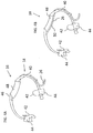
FIG. 4A is an isometric view of an applicator and support structure, constructed and operative according to the teachings of the present invention, for implementing a first preferred embodiment of the system ofFigure 1 ; -
FIG. 4B is a view similar toFigure 4A with an absorbent element of the applicator removed; -
FIG. 5 is an isometric view of a first preferred embodiment of the system ofFigure 1 employing the applicator and support structure ofFigure 4A ; -
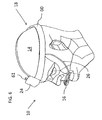
FIG. 6 is an isometric view of a second preferred embodiment of the system ofFigure 1 ; -
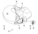
FIG. 7A is an isometric view of a third preferred embodiment of the system ofFigure 1 ; -
FIG. 7B is an enlarged view of the circled portion ofFigure 7A as shown; -
FIG. 8A is an isometric view of a fourth preferred embodiment of the system ofFigure 1 ; -
FIG. 8B is an enlarged view of the circled portion ofFigure 8A designated "A"; -
FIG. 9A is an isometric view of a fifth preferred embodiment of the system ofFigure 1 ; -
FIG. 9B is an enlarged view of the circled portion ofFigure 9A designated "A"; -
FIG. 10A is an isometric view of a sixth preferred embodiment of the system ofFigure 1 ; -
FIG. 10B is an enlarged view of the circled portion ofFigure 10A as shown; -
FIG. 11A is an isometric view of a seventh preferred embodiment of the system ofFigure 1 ; and -
FIG. 11B is an enlarged view of the circled portion ofFigure 11A as shown. - The present invention is a system and corresponding method for delivering moisturizing liquid to the lips of a subject suffering from dry lips.
- The principles and operation of systems and methods according to the present invention may be better understood with reference to the drawings and the accompanying description.
- Referring now to the drawings,
Figure 1 illustrates schematically a system, generally designated 10, and a corresponding method according to the teachings of the present invention for delivering moisturizingliquid 12 to the lips of a subject 14. In general terms,system 10 includes anapplicator 16 for applying the moisturizing liquid to the lips of the subject, and asupport structure 18.Support structure 18 is arranged to supportapplicator 16 so that at least a part ofapplicator 16 is deployed so as to engage a recess between the lips of subject 14 without obstructing contact between the subject's upper and lower lips. - It will be noted that the positioning of
applicator 16 as described herein, engaging the recess between the lips but without obstructing closure of the lips together, is highly advantageous. On one hand, the proximity ofapplicator 16 to the lips allows the use of simple contact-based implementations ofapplicator 16, thereby providing continuous and mess-free relief to the discomfort of the subject without requiring complex or expensive applicator devices. At the same time, by avoiding any obstruction to contact between the lips, disruption of speech and other normal oral movement is avoided, thereby making the system as non-intrusive as possible. These and other advantages of the systems and methods of the present invention will become clearer from the following detailed description. - Before addressing the features of the present invention in more detail, it will be helpful to define certain terminology as used herein in the description and claims. Firstly, the term "recess" is used herein in the description and claims to refer to a geometrical form in two dimensions, corresponding to the outline of a body part, which can be closed by addition of a single straight line to enclose an area. This definition is represented graphically in
Figure 2 in which the outline of theface 14, taken in side view (or cross-section) exhibits a recess between the lips, while the lips are closed together, which can be closed in geometrically by addition of a single straight line, as illustrated by dashedline 20. Thearea 22 enclosed by the body part together with the straight line is referred to as "within the recess". An object located at least partially within the recess is referred to as "engaging the recess", without necessarily requiring it to be in contact with sides of the recess continuously. In all of the above terminology, it will be noted that the definitions refer to geometrical relations in two dimensions only, and particularly relating to an outline as viewed in a cross-section in the sagittal plane with the mouth closed. Clearly, the geometry of the human mouth is somewhat convexly curved in the side-to-side direction, and the recess referred to above may be an open-ended channel in three dimensions, or may otherwise change towards its lateral edges. - When reference is made to an applicator being positioned such that is does not "obstruct contact between the subject's upper and lower lips," this used to indicate that the lips are free to contact each other directly across the entire width of the mouth without any intervening object or material. This terminology thus excludes all types of devices which have portions extending into the mouth, or which are mounted in various manners to the lips or teeth.
- Turning now to the remaining features of the schematic representation of
system 10 illustrated inFigure 1 , the various implementations of the present invention preferably include areservoir 24 for containing a quantity of moisturizingliquid 12, and a supply arrangement, illustrated here as afluid flow conduit 26, in fluid communication withreservoir 24 andapplicator 16 for supplying moisturizingliquid 12 toapplicator 16. -
Liquid 12 itself may be any non-toxic liquid effective for moistening the lips. The liquid is typically water-based, and may have additives to provide a sweet taste or any other desired flavor, additives to improve efficacy for treatment of dry lips or any other desired additives. Where additives are present, they may be in the form of a solution, a suspension, an emulsion or any other form. Most preferably, plain water is used. In certain cases, particularly where the subject is at risk of infection, sterilized water may be used. In many cases, regular drinking water may be sufficient. -
Figures 3A and 3B show an enlarged view ofapplicator 16 deployed in engagement with the recess between the lips of a subject while the subject's mouth is open and closed, respectively. As seen here,applicator 16 is preferably kept in proximity to the lips during movement of the mouth, but does not obstruct normal opening and closing movement of the mouth, or any other motion of the mouth normally required for speech or facial expression. - Turning now to
Figures 4-11B , it should be noted thatsystem 10 as described schematically with reference toFigures 1-3B above may be implemented in a large number of practical implementations. More specifically, while maintaining the common functional features described thus far, each ofapplicator 16,support structure 18,reservoir 24 andsupply arrangement 26 may be implemented in numerous ways. In order to give some indication of the scope of possible implementations,system 10 will be further illustrated with reference to seven non-limiting exemplary embodiments. The first three of theseemploy support structures 18 which are configured to be supported primarily by at least one part of the body of the subject, and most preferably, part of the head of the subject, thereby maintaining the desired position relative to the lips of the subject even if the subject moves around considerably. The latter four embodiments employvarious support structures 18 which cooperate with the frame or other surfaces of a bed, an intravenous drip stand or other nearby furniture. It should be noted that, unless otherwise indicated, the various implementations of each component ofsystem 10 may be used interchangeably between the embodiments, and are not limited to the specific combinations illustrated here. - Turning specifically to
Figures 4A, 4B and5 , this illustrates a first embodiment ofsystem 10 whereinsupport structure 18 is primarily supported by contact with the cheeks ofsubject 14. In this case,support structure 18 is formed as aresilient frame 40, shown here with a roughly arcuate shape, withcheek contact regions 42 provided bygrip elements 44.Grip elements 44 are preferably formed from relatively soft resilient material, such as natural or synthetic rubber or silicone, which provide firm but comfortable grip on the cheeks of the subject.Grip elements 44 may be slidably mounted on the arms offrame 40 to provide adjustment of the size of the subject.Frame 40 is typically formed from low-cost injection-molded plastic. - A central portion of
frame 40 preferably includes a flattenedregion 46 which protrudes inwardly, forming a convex contour which contrasts with the generally concave curvature of the inside of the arcuate shape. This portion provides support for, and defines the shape of, theapplicator 16 of this embodiment, as will now be described. -
Applicator 16 in this embodiment includes an absorbent material moistened byliquid 12 which serves to disperse the liquid over a desired contact area through capillary action.Liquid 12 is applied to the lips as they come into contact with the moistened absorbent material. In the preferred case illustrated here (Figure 4A ), the absorbent material is implemented as alayer 48 of woven or non-woven cloth or open-cell foam material wrapped around flattenedregion 46 offrame 40. - Supply of
liquid 12 to layer 48 occurs viafluid flow conduit 26 which has one or moreliquid release aperture 50, as revealed inFigure 4B . Parenthetically, it should be noted that a structure such as shown inFigure 4B , without absorbent material, may be used directly as an applicator, optionally provided with a plurality of openings to distribute the liquid more evenly across the lips.Conduit 26 as shown here passes along one side offrame 40, typically held in place by a number of clips integrally formed with the frame, and extends around the inward-facing edge of flattenedregion 46 whereaperture 50 is located. In this manner, fluid supply is ensured primarily to the absorbent material on the side of flattenedregion 46 facing the lips. In the case shown here,conduit 26 passes through a lateral opening formed inframe 40 so as to pass neatly from the outside to the inside of the arcuate frame. -
Figure 5 illustrates the system in use withgrip elements 44 gripping the subject's cheeks andapplicator 16 engaged in the recess between the lips of the subject, but without obstructing contact between the lips. - The device of
Figures 4A-4B may be used to advantage with substantially any form ofreservoir 24 and liquid supply arrangement. In the example illustrated inFigure 5 , a gravity-fed liquid supply arrangement with a suspended flexible reservoir "bag" of a type familiar from intravenous drip ("I.V.") arrangements is shown. A simpleflow regulating control 52, also of a type commonly used in I.V. sets, may be used to limit the flow rate to a suitable flow rate. Additionally, or alternatively, this and other embodiments of the present invention may include aflow limiting element 53 incorporated withinconduit 26, or at any other point along the flow path, to limit the flow rate to a suitable level. Suitable flow rate limiting elements may be implemented using well developed technology (e.g., flow labyrinths or pressure-regulating diaphragms) common in drip irrigation systems which provide a desired flow rate largely independent of variations in the supply pressure. - According to one particular example of a flow limiting element, a capillary tube is incorporated within the flow path. Preferably, the capillary tube has an internal diameter of between about 0.05 mm and about 0.2 mm, and most preferably about 0.1 ± 0.03 mm. To facilitate attachment of the capillary tube, and external diameter of about 3 mm has been found convenient. A length of the capillary is preferably between about 5 and about 30 mm, and most preferably about 8 ±3 mm. Such a capillary can conveniently be attached at the end of
conduit 26 or otherwise be deployed to define an outlet toapplicator 16. In experiments performed by the applicant, a glass capillary tube of internal diameter 0.1 mm and length 8 mm has been found effective when used with an infusion bag supply positioned 70-110 cm above the outlet to maintain flow rates of around 10 cc. per hour. - Turning now to
Figure 6 , there is shown an alternative embodiment ofsystem 10, in this case employing asupport structure 18 which suspendsapplicator 16 from a hat or head-band 60 substantially encircling the crown of the subject 14. In the case illustrated here,reservoir 24 is shown mounted directly on head-band 60. Optionally,reservoir 24 may have anopening 61 for convenient refilling ofreservoir 24.Applicator 16 may be suspended from head-band 60 via any suitable suspension arrangement. Preferably, one or more stiff arm is used to retain the applicator in place. Optionally, the arm may be deformable in order to allow repositioning of the applicator in the correct position for the subject. According to a particularly preferred option illustrated here,conduit 26 may itself be implemented as a tube sufficiently stiff to provide the repositionable deployment as described. -
Applicator 16 as illustrated here is a hollow body, typically of plastic, with an array of small openings for releasing liquid. The size of the openings, as well as coatings or other surface properties of the applicator, may be chosen to provide drip-free retention of liquid at the openings through surface tension effects. Liquid is then released by contact against the lips of the subject. - Turning now to
Figures 7A and 7B , this illustrated a further alternative embodiment ofsystem 10 in which supportstructure 18 is implemented with an eye-glasses-type support frame which engages at least one and preferably both ears of the subject 14. In the version shown here,support structure 18 also features a bridge portion lying across the bridge of the subject's nose. These features together provide a well defined support geometry, allowing precise positioning ofapplicator 16 within the recess between the lips of the subject. - One attractive option for this implementation is positioning
reservoir 24 over and/or behind the ears. In order to ensure comfortable balance between the two sides, it may be preferably to provide two similar reservoirs on opposite sides of the support structure, one resting on each ear. flow conduit(s) 26 are preferably implemented as part ofsupport structure 18, or as thin tubes passing within the structure. Flow fromreservoirs 24 toapplicator 16 is preferably achieved through capillary action drawing water through the fine tubes ofsupport structure 18 toapplicator 16. -
Applicator 16 as shown here, best seen inFigure 7B , is implemented in a manner conceptually similar to that ofFigure 4A , with an absorbent material deployed around a tube with drop release apertures. - Turning now to
Figures 8A and 8B , there is shown an implementation ofsystem 10 in which supportstructure 18 is an adjustable jointed stand with a base configured to be self-supporting when placed on a flat surface, such as the surface of a bed. This allows positioning ofapplicator 16 in an appropriate position for short term use by a subject confined to bed, such as for example while recovering from anesthesia.Applicator 16, shown more clearly inFigure 8B , is similar to that ofFigure 6 . - A
reservoir 24 is here provided at or near the base ofstand 18, and is connected toapplicator 16 via aconduit 26. A driving force for supplying liquid toapplicator 16 is provided by a spring-clamp 80 applied so as to apply pressure to external surfaces offlexible reservoir 24. The pressure of the spring-clamp maintains moisturizingliquid 12 withinreservoir 24 at a pressure above atmospheric pressure, thereby generating liquid flow to the applicator. - Turning now to
Figures 9A and 9B , these show a further variant embodiment based on a raisedreservoir 24 mounted on abracket 90 which holds it at a level above the subject by clamping to part of a bed frame.Applicator 16 is here shown as a tube with a number of apertures formed at the end of asemi-rigid conduit 26 connectingapplicator 16 toreservoir 14. -
Figures 10A and 10B illustrate an implementation generally similar to that ofFigures 8A and 8B , but in whichreservoir 24 is pressurized by the weight of a part of the subject's body, in this case the head, resting onreservoir 24, thereby feeding the moisturizing liquid toapplicator 16. Most preferably,reservoir 24 may be located within or under a pillow to be used by the subject.Applicator 16 itself is shown here as a single drop emitter mounted at the end ofconduit 26. - Turning finally to
Figures 11A and 11B , it should be noted that not all embodiments necessarily require adistinct conduit 26 connecting betweenreservoir 24 andapplicator 16 as shown in the previous embodiments. Instead, in this embodiment,reservoir 24 is formed as an integrated part ofapplicator 16. The device is thus essentially a hangingreservoir 24 with anapplicator 16 formed in its lower portion. The device is hung from a suitable stand, thereby achieving the desired positioning of theapplicator 16 in the recess between the lips of the subject without obstructing contact between the lips. - Once again, it should be stressed that the various implementations of different elements of
system 10 shown herein are not limited to the particular combinations illustrated. Thus, for example, the embodiments ofFigures 4A, 4B and5 may be implemented using a head mounted reservoir such as was shown inFigure 6 , or various other gravity-fed, pre-pressurized or body-weight pressurized reservoir arrangements. A manually-operable supply (e.g., a squeezable reservoir or a small manually-operable pump such as is common in liquid soap dispensers) also falls within the scope of the present invention. - It will be appreciated that the above descriptions are intended only to serve as examples, and that many other embodiments are possible within the scope of the present invention as defined in the appended claims.
Claims (9)
- A system (10) for delivering moisturizing liquid (12) to the lips of a subject (14), the system comprising:(a) a reservoir (24) for containing a quantity of the moisturizing liquid;(b) an applicator (16) for applying the moisturizing liquid to the lips of the subject;(c) a supply arrangement (26) in fluid communication with said reservoir and said applicator for supplying the moisturizing liquid to said applicator; and(d) a support structure (18) configured for supporting said applicator, characterized in that said applicator (16) has a part configured to engage a recess between the lips, without insertion into the mouth, said part provided with an absorbent material (48) deployed so as to be moistened by the moisturizing liquid from said supply arrangement (26).
- The system of claim 1, wherein said supply arrangement (26) includes a flow restriction comprising a length of capillary tube having an internal diameter no greater than 0.2 mm.
- The system of any preceding claim, wherein said support structure (18) is adapted to be supported primarily by at least one part of the body of the subject so as to position said applicator (16) for engaging a recess between the lips of the subject without obstructing contact between the upper and lower lips of the subject.
- The system of any preceding claim, wherein said support structure (18) is adapted to be supported at least in part by contact with the cheeks of the subject.
- The system of any of claims 1-3, wherein said support structure (18) is adapted to be supported at least in part by engagement with features of at least one ear of the subject.
- The system of claim 1 or claim 2, wherein said support structure (18) includes: a clamp for clamping said support structure to a bed; or a base configured to be self-supporting when placed on a flat surface.
- The system of any preceding claim, wherein said liquid supply arrangement is a gravity-fed liquid supply arrangement.
- The system of any of claims 1-6, wherein said reservoir maintains the moisturizing liquid at a pressure above atmospheric pressure, said pressure generating liquid flow to said applicator.
- The system of any of claims 1-6, wherein said reservoir is pressurized by the weight of a part of the subject's body resting on said reservoir, thereby feeding the moisturizing liquid to said applicator.
Applications Claiming Priority (2)
| Application Number | Priority Date | Filing Date | Title |
|---|---|---|---|
| US2750308P | 2008-02-11 | 2008-02-11 | |
| PCT/IB2009/050559 WO2009101585A2 (en) | 2008-02-11 | 2009-02-11 | System and method for delivering moisturizing liquid to lips of a subject |
Publications (3)
| Publication Number | Publication Date |
|---|---|
| EP2242438A2 EP2242438A2 (en) | 2010-10-27 |
| EP2242438A4 EP2242438A4 (en) | 2011-03-30 |
| EP2242438B1 true EP2242438B1 (en) | 2012-09-05 |
Family
ID=40957334
Family Applications (1)
| Application Number | Title | Priority Date | Filing Date |
|---|---|---|---|
| EP09710980A Active EP2242438B1 (en) | 2008-02-11 | 2009-02-11 | System for delivering moisturizing liquid to lips of a subject |
Country Status (4)
| Country | Link |
|---|---|
| US (1) | US8679077B2 (en) |
| EP (1) | EP2242438B1 (en) |
| ES (1) | ES2394271T3 (en) |
| WO (1) | WO2009101585A2 (en) |
Families Citing this family (6)
| Publication number | Priority date | Publication date | Assignee | Title |
|---|---|---|---|---|
| US8038650B2 (en) * | 2010-02-22 | 2011-10-18 | Microsert Ltd. | Slow release liquid drug delivery device |
| USD747462S1 (en) * | 2012-08-08 | 2016-01-12 | Imd Tech Ltd. | Device for delivering moisturizing liquid to the lips of a patient |
| US20160082457A1 (en) * | 2014-09-23 | 2016-03-24 | John Niehaus | Human hydration system |
| CN208694027U (en) * | 2017-11-27 | 2019-04-05 | Imd科技有限公司 | System for delivering moisturizing fluid to the lips of a subject |
| CN110354376A (en) * | 2019-08-12 | 2019-10-22 | 固安博健生物技术有限公司 | An ear-hanging instrument for effectively keeping lips moist |
| CN119746257B (en) * | 2025-02-08 | 2025-09-26 | 中国人民解放军联勤保障部队第九〇〇医院 | A micro humidity control constant humidity lip protector and its automatic adjustment device |
Family Cites Families (18)
| Publication number | Priority date | Publication date | Assignee | Title |
|---|---|---|---|---|
| EP0156409A3 (en) * | 1984-02-23 | 1986-06-25 | Jean Michel Anthony | Device for moistening parts of the human body |
| US5062795A (en) | 1987-06-22 | 1991-11-05 | Woog Philippe G E | Therapeutically caring for the mouth and throat |
| US4838882A (en) | 1988-04-04 | 1989-06-13 | Molinoff Henry C | Mouth moisturizing pad |
| US4917674A (en) | 1988-04-04 | 1990-04-17 | Molinoff Henry C | Mouth moisturizing device |
| US4893956A (en) * | 1988-11-18 | 1990-01-16 | Blistex Inc. | Packaging for medicaments |
| US5055108A (en) | 1990-05-25 | 1991-10-08 | Jenkins E Preston | Appliance for maintaining moisture in the mouth |
| FR2752696B1 (en) * | 1996-09-02 | 1998-09-25 | Oreal | LIQUID OR SEMI-LIQUID APPLICATOR AND APPLICATION ASSEMBLY USING SUCH AN APPLICATOR |
| US6082583A (en) * | 1997-04-04 | 2000-07-04 | Belmont Housing Corporation | Device and method for providing liquid to a user's mouth |
| US5927661A (en) * | 1997-06-05 | 1999-07-27 | Tinsley; Kevin L. | Bottle suspension apparatus |
| US6053898A (en) * | 1998-01-02 | 2000-04-25 | Electromagnetic Bracing Systems, Inc. | Medication dispensing system |
| US6450166B1 (en) * | 2000-05-17 | 2002-09-17 | Southmedic Incorporated | Patient oxygen delivery system |
| US6536423B2 (en) * | 2000-08-14 | 2003-03-25 | Patrick J Conway | Patient activated mouth moisturizer |
| GB0130057D0 (en) * | 2001-12-14 | 2002-02-06 | Dunne Stephen T | Liquid atomising system |
| US6691706B2 (en) * | 2002-01-02 | 2004-02-17 | Thomas Harrison Ives | Personal humidifier |
| US7416358B2 (en) * | 2003-04-15 | 2008-08-26 | L'oreal | Applicator intended to be attached to a finger |
| US20050066463A1 (en) * | 2003-09-25 | 2005-03-31 | Brunner Michael S. | Substrates and devices for applying a lip care formulation |
| EP1810712A4 (en) | 2004-11-08 | 2009-11-04 | Mitsubishi Pencil Co | Liquid applicator |
| US20080019758A1 (en) * | 2006-07-21 | 2008-01-24 | Mallardi Vincent Iii | Lip applicator |
-
2009
- 2009-02-11 EP EP09710980A patent/EP2242438B1/en active Active
- 2009-02-11 US US12/866,291 patent/US8679077B2/en active Active
- 2009-02-11 ES ES09710980T patent/ES2394271T3/en active Active
- 2009-02-11 WO PCT/IB2009/050559 patent/WO2009101585A2/en not_active Ceased
Also Published As
| Publication number | Publication date |
|---|---|
| WO2009101585A3 (en) | 2009-12-23 |
| WO2009101585A2 (en) | 2009-08-20 |
| US8679077B2 (en) | 2014-03-25 |
| ES2394271T3 (en) | 2013-01-30 |
| EP2242438A4 (en) | 2011-03-30 |
| US20100324508A1 (en) | 2010-12-23 |
| EP2242438A2 (en) | 2010-10-27 |
Similar Documents
| Publication | Publication Date | Title |
|---|---|---|
| US8679077B2 (en) | System and method for delivering moisturizing liquid to lips of a subject | |
| EP3478351B1 (en) | Cannula device for high flow therapy | |
| US6298850B1 (en) | Nasal cannula assembly and securing device | |
| AU2006342046B2 (en) | Patient interface device with dampening cushion | |
| ES2817076T3 (en) | Asymmetric Nasal Delivery Elements and Accessories for Nasal Interfaces | |
| ES2576454T3 (en) | Administration of respiratory therapy | |
| US8857434B2 (en) | Retainer clip for securing breathing devices | |
| US20250143855A1 (en) | Device for distribution of a liquid in a user's mouth | |
| KR20160071363A (en) | Sleep apnea prevention mask | |
| US20160317773A1 (en) | Strapless nasal interface device | |
| KR200495116Y1 (en) | Pillow for patients that secures airway and protects cervical nerve | |
| RU195989U1 (en) | DELIVERY SYSTEM FOR MOISTURIZING LIQUID TO LIPS OF SUBJECT | |
| KR20220000008U (en) | System and method for delivering moisturizing liquid to lips of a subject | |
| US20170056235A1 (en) | Oral appliance | |
| US10441737B2 (en) | Strapless nasal interface device | |
| CA3150519C (en) | Device for distribution of a liquid in a user's mouth | |
| SE462466B (en) | IMPLANTABLE DEVICE FOR SUPPLY OF SALIVATING SUBSTANCE | |
| CN110812652B (en) | A kind of burn earmuff for oxygen tube protection | |
| HK40055264A (en) | Cannula device for high flow therapy | |
| AU2001276152B2 (en) | Nasal mask with integral mouldable straps | |
| CN207412360U (en) | Modified form operation water bag | |
| WO2019094853A1 (en) | Strapless nasal interface device | |
| JP2007050206A (en) | Liquid supply system for oral cavity |
Legal Events
| Date | Code | Title | Description |
|---|---|---|---|
| PUAI | Public reference made under article 153(3) epc to a published international application that has entered the european phase |
Free format text: ORIGINAL CODE: 0009012 |
|
| 17P | Request for examination filed |
Effective date: 20100913 |
|
| AK | Designated contracting states |
Kind code of ref document: A2 Designated state(s): AT BE BG CH CY CZ DE DK EE ES FI FR GB GR HR HU IE IS IT LI LT LU LV MC MK MT NL NO PL PT RO SE SI SK TR |
|
| AX | Request for extension of the european patent |
Extension state: AL BA RS |
|
| A4 | Supplementary search report drawn up and despatched |
Effective date: 20110302 |
|
| RIC1 | Information provided on ipc code assigned before grant |
Ipc: A61M 35/00 20060101ALI20110224BHEP Ipc: A61B 19/00 20060101AFI20100812BHEP |
|
| DAX | Request for extension of the european patent (deleted) | ||
| GRAP | Despatch of communication of intention to grant a patent |
Free format text: ORIGINAL CODE: EPIDOSNIGR1 |
|
| RTI1 | Title (correction) |
Free format text: SYSTEM FOR DELIVERING MOISTURIZING LIQUID TO LIPS OF A SUBJECT |
|
| GRAS | Grant fee paid |
Free format text: ORIGINAL CODE: EPIDOSNIGR3 |
|
| GRAA | (expected) grant |
Free format text: ORIGINAL CODE: 0009210 |
|
| AK | Designated contracting states |
Kind code of ref document: B1 Designated state(s): AT BE BG CH CY CZ DE DK EE ES FI FR GB GR HR HU IE IS IT LI LT LU LV MC MK MT NL NO PL PT RO SE SI SK TR |
|
| REG | Reference to a national code |
Ref country code: GB Ref legal event code: FG4D |
|
| REG | Reference to a national code |
Ref country code: CH Ref legal event code: EP |
|
| REG | Reference to a national code |
Ref country code: AT Ref legal event code: REF Ref document number: 573728 Country of ref document: AT Kind code of ref document: T Effective date: 20120915 |
|
| REG | Reference to a national code |
Ref country code: IE Ref legal event code: FG4D |
|
| REG | Reference to a national code |
Ref country code: DE Ref legal event code: R096 Ref document number: 602009009457 Country of ref document: DE Effective date: 20121031 |
|
| REG | Reference to a national code |
Ref country code: NL Ref legal event code: T3 |
|
| REG | Reference to a national code |
Ref country code: SE Ref legal event code: TRGR |
|
| REG | Reference to a national code |
Ref country code: AT Ref legal event code: MK05 Ref document number: 573728 Country of ref document: AT Kind code of ref document: T Effective date: 20120905 |
|
| REG | Reference to a national code |
Ref country code: ES Ref legal event code: FG2A Ref document number: 2394271 Country of ref document: ES Kind code of ref document: T3 Effective date: 20130130 |
|
| PG25 | Lapsed in a contracting state [announced via postgrant information from national office to epo] |
Ref country code: CY Free format text: LAPSE BECAUSE OF FAILURE TO SUBMIT A TRANSLATION OF THE DESCRIPTION OR TO PAY THE FEE WITHIN THE PRESCRIBED TIME-LIMIT Effective date: 20120905 Ref country code: HR Free format text: LAPSE BECAUSE OF FAILURE TO SUBMIT A TRANSLATION OF THE DESCRIPTION OR TO PAY THE FEE WITHIN THE PRESCRIBED TIME-LIMIT Effective date: 20120905 Ref country code: FI Free format text: LAPSE BECAUSE OF FAILURE TO SUBMIT A TRANSLATION OF THE DESCRIPTION OR TO PAY THE FEE WITHIN THE PRESCRIBED TIME-LIMIT Effective date: 20120905 Ref country code: NO Free format text: LAPSE BECAUSE OF FAILURE TO SUBMIT A TRANSLATION OF THE DESCRIPTION OR TO PAY THE FEE WITHIN THE PRESCRIBED TIME-LIMIT Effective date: 20121205 Ref country code: AT Free format text: LAPSE BECAUSE OF FAILURE TO SUBMIT A TRANSLATION OF THE DESCRIPTION OR TO PAY THE FEE WITHIN THE PRESCRIBED TIME-LIMIT Effective date: 20120905 Ref country code: LT Free format text: LAPSE BECAUSE OF FAILURE TO SUBMIT A TRANSLATION OF THE DESCRIPTION OR TO PAY THE FEE WITHIN THE PRESCRIBED TIME-LIMIT Effective date: 20120905 |
|
| REG | Reference to a national code |
Ref country code: LT Ref legal event code: MG4D Effective date: 20120905 |
|
| PG25 | Lapsed in a contracting state [announced via postgrant information from national office to epo] |
Ref country code: SI Free format text: LAPSE BECAUSE OF FAILURE TO SUBMIT A TRANSLATION OF THE DESCRIPTION OR TO PAY THE FEE WITHIN THE PRESCRIBED TIME-LIMIT Effective date: 20120905 Ref country code: LV Free format text: LAPSE BECAUSE OF FAILURE TO SUBMIT A TRANSLATION OF THE DESCRIPTION OR TO PAY THE FEE WITHIN THE PRESCRIBED TIME-LIMIT Effective date: 20120905 Ref country code: GR Free format text: LAPSE BECAUSE OF FAILURE TO SUBMIT A TRANSLATION OF THE DESCRIPTION OR TO PAY THE FEE WITHIN THE PRESCRIBED TIME-LIMIT Effective date: 20121206 |
|
| PG25 | Lapsed in a contracting state [announced via postgrant information from national office to epo] |
Ref country code: BE Free format text: LAPSE BECAUSE OF FAILURE TO SUBMIT A TRANSLATION OF THE DESCRIPTION OR TO PAY THE FEE WITHIN THE PRESCRIBED TIME-LIMIT Effective date: 20120905 Ref country code: CZ Free format text: LAPSE BECAUSE OF FAILURE TO SUBMIT A TRANSLATION OF THE DESCRIPTION OR TO PAY THE FEE WITHIN THE PRESCRIBED TIME-LIMIT Effective date: 20120905 Ref country code: EE Free format text: LAPSE BECAUSE OF FAILURE TO SUBMIT A TRANSLATION OF THE DESCRIPTION OR TO PAY THE FEE WITHIN THE PRESCRIBED TIME-LIMIT Effective date: 20120905 Ref country code: IS Free format text: LAPSE BECAUSE OF FAILURE TO SUBMIT A TRANSLATION OF THE DESCRIPTION OR TO PAY THE FEE WITHIN THE PRESCRIBED TIME-LIMIT Effective date: 20130105 Ref country code: RO Free format text: LAPSE BECAUSE OF FAILURE TO SUBMIT A TRANSLATION OF THE DESCRIPTION OR TO PAY THE FEE WITHIN THE PRESCRIBED TIME-LIMIT Effective date: 20120905 |
|
| PG25 | Lapsed in a contracting state [announced via postgrant information from national office to epo] |
Ref country code: PT Free format text: LAPSE BECAUSE OF FAILURE TO SUBMIT A TRANSLATION OF THE DESCRIPTION OR TO PAY THE FEE WITHIN THE PRESCRIBED TIME-LIMIT Effective date: 20130107 Ref country code: PL Free format text: LAPSE BECAUSE OF FAILURE TO SUBMIT A TRANSLATION OF THE DESCRIPTION OR TO PAY THE FEE WITHIN THE PRESCRIBED TIME-LIMIT Effective date: 20120905 Ref country code: SK Free format text: LAPSE BECAUSE OF FAILURE TO SUBMIT A TRANSLATION OF THE DESCRIPTION OR TO PAY THE FEE WITHIN THE PRESCRIBED TIME-LIMIT Effective date: 20120905 |
|
| PLBE | No opposition filed within time limit |
Free format text: ORIGINAL CODE: 0009261 |
|
| STAA | Information on the status of an ep patent application or granted ep patent |
Free format text: STATUS: NO OPPOSITION FILED WITHIN TIME LIMIT |
|
| PG25 | Lapsed in a contracting state [announced via postgrant information from national office to epo] |
Ref country code: DK Free format text: LAPSE BECAUSE OF FAILURE TO SUBMIT A TRANSLATION OF THE DESCRIPTION OR TO PAY THE FEE WITHIN THE PRESCRIBED TIME-LIMIT Effective date: 20120905 Ref country code: BG Free format text: LAPSE BECAUSE OF FAILURE TO SUBMIT A TRANSLATION OF THE DESCRIPTION OR TO PAY THE FEE WITHIN THE PRESCRIBED TIME-LIMIT Effective date: 20121205 |
|
| 26N | No opposition filed |
Effective date: 20130606 |
|
| PG25 | Lapsed in a contracting state [announced via postgrant information from national office to epo] |
Ref country code: MC Free format text: LAPSE BECAUSE OF NON-PAYMENT OF DUE FEES Effective date: 20130228 |
|
| REG | Reference to a national code |
Ref country code: DE Ref legal event code: R097 Ref document number: 602009009457 Country of ref document: DE Effective date: 20130606 |
|
| REG | Reference to a national code |
Ref country code: IE Ref legal event code: MM4A |
|
| PG25 | Lapsed in a contracting state [announced via postgrant information from national office to epo] |
Ref country code: IE Free format text: LAPSE BECAUSE OF NON-PAYMENT OF DUE FEES Effective date: 20130211 |
|
| PG25 | Lapsed in a contracting state [announced via postgrant information from national office to epo] |
Ref country code: MT Free format text: LAPSE BECAUSE OF FAILURE TO SUBMIT A TRANSLATION OF THE DESCRIPTION OR TO PAY THE FEE WITHIN THE PRESCRIBED TIME-LIMIT Effective date: 20120905 |
|
| PG25 | Lapsed in a contracting state [announced via postgrant information from national office to epo] |
Ref country code: TR Free format text: LAPSE BECAUSE OF FAILURE TO SUBMIT A TRANSLATION OF THE DESCRIPTION OR TO PAY THE FEE WITHIN THE PRESCRIBED TIME-LIMIT Effective date: 20120905 |
|
| PG25 | Lapsed in a contracting state [announced via postgrant information from national office to epo] |
Ref country code: MK Free format text: LAPSE BECAUSE OF FAILURE TO SUBMIT A TRANSLATION OF THE DESCRIPTION OR TO PAY THE FEE WITHIN THE PRESCRIBED TIME-LIMIT Effective date: 20120905 Ref country code: HU Free format text: LAPSE BECAUSE OF FAILURE TO SUBMIT A TRANSLATION OF THE DESCRIPTION OR TO PAY THE FEE WITHIN THE PRESCRIBED TIME-LIMIT; INVALID AB INITIO Effective date: 20090211 Ref country code: LU Free format text: LAPSE BECAUSE OF NON-PAYMENT OF DUE FEES Effective date: 20130211 |
|
| REG | Reference to a national code |
Ref country code: FR Ref legal event code: PLFP Year of fee payment: 8 |
|
| REG | Reference to a national code |
Ref country code: FR Ref legal event code: PLFP Year of fee payment: 9 |
|
| REG | Reference to a national code |
Ref country code: FR Ref legal event code: PLFP Year of fee payment: 10 |
|
| PGFP | Annual fee paid to national office [announced via postgrant information from national office to epo] |
Ref country code: NL Payment date: 20230216 Year of fee payment: 15 |
|
| PGFP | Annual fee paid to national office [announced via postgrant information from national office to epo] |
Ref country code: CH Payment date: 20230307 Year of fee payment: 15 |
|
| PGFP | Annual fee paid to national office [announced via postgrant information from national office to epo] |
Ref country code: SE Payment date: 20230216 Year of fee payment: 15 Ref country code: IT Payment date: 20230223 Year of fee payment: 15 Ref country code: DE Payment date: 20230216 Year of fee payment: 15 |
|
| PGFP | Annual fee paid to national office [announced via postgrant information from national office to epo] |
Ref country code: ES Payment date: 20240325 Year of fee payment: 16 |
|
| PGFP | Annual fee paid to national office [announced via postgrant information from national office to epo] |
Ref country code: GB Payment date: 20240219 Year of fee payment: 16 |
|
| PGFP | Annual fee paid to national office [announced via postgrant information from national office to epo] |
Ref country code: FR Payment date: 20240221 Year of fee payment: 16 |
|
| REG | Reference to a national code |
Ref country code: DE Ref legal event code: R119 Ref document number: 602009009457 Country of ref document: DE |
|
| REG | Reference to a national code |
Ref country code: CH Ref legal event code: PL |
|
| REG | Reference to a national code |
Ref country code: SE Ref legal event code: EUG |
|
| REG | Reference to a national code |
Ref country code: NL Ref legal event code: MM Effective date: 20240301 |
|
| PG25 | Lapsed in a contracting state [announced via postgrant information from national office to epo] |
Ref country code: CH Free format text: LAPSE BECAUSE OF NON-PAYMENT OF DUE FEES Effective date: 20240229 |
|
| PG25 | Lapsed in a contracting state [announced via postgrant information from national office to epo] |
Ref country code: CH Free format text: LAPSE BECAUSE OF NON-PAYMENT OF DUE FEES Effective date: 20240229 |
|
| PG25 | Lapsed in a contracting state [announced via postgrant information from national office to epo] |
Ref country code: NL Free format text: LAPSE BECAUSE OF NON-PAYMENT OF DUE FEES Effective date: 20240301 |
|
| PG25 | Lapsed in a contracting state [announced via postgrant information from national office to epo] |
Ref country code: NL Free format text: LAPSE BECAUSE OF NON-PAYMENT OF DUE FEES Effective date: 20240301 |
|
| PG25 | Lapsed in a contracting state [announced via postgrant information from national office to epo] |
Ref country code: DE Free format text: LAPSE BECAUSE OF NON-PAYMENT OF DUE FEES Effective date: 20240903 |
|
| PG25 | Lapsed in a contracting state [announced via postgrant information from national office to epo] |
Ref country code: DE Free format text: LAPSE BECAUSE OF NON-PAYMENT OF DUE FEES Effective date: 20240903 |
|
| PG25 | Lapsed in a contracting state [announced via postgrant information from national office to epo] |
Ref country code: IT Free format text: LAPSE BECAUSE OF NON-PAYMENT OF DUE FEES Effective date: 20240211 |
|
| PG25 | Lapsed in a contracting state [announced via postgrant information from national office to epo] |
Ref country code: SE Free format text: LAPSE BECAUSE OF NON-PAYMENT OF DUE FEES Effective date: 20240212 |
|
| GBPC | Gb: european patent ceased through non-payment of renewal fee |
Effective date: 20250211 |
|
| PG25 | Lapsed in a contracting state [announced via postgrant information from national office to epo] |
Ref country code: GB Free format text: LAPSE BECAUSE OF NON-PAYMENT OF DUE FEES Effective date: 20250211 |
|
| PG25 | Lapsed in a contracting state [announced via postgrant information from national office to epo] |
Ref country code: FR Free format text: LAPSE BECAUSE OF NON-PAYMENT OF DUE FEES Effective date: 20250228 |
|
| REG | Reference to a national code |
Ref country code: ES Ref legal event code: FD2A Effective date: 20260330 |
|
| PG25 | Lapsed in a contracting state [announced via postgrant information from national office to epo] |
Ref country code: ES Free format text: LAPSE BECAUSE OF NON-PAYMENT OF DUE FEES Effective date: 20250212 |