EP2242113A2 - Apparatus for coupling power generated by a photovoltaic module to an output - Google Patents
Apparatus for coupling power generated by a photovoltaic module to an output Download PDFInfo
- Publication number
- EP2242113A2 EP2242113A2 EP10160056A EP10160056A EP2242113A2 EP 2242113 A2 EP2242113 A2 EP 2242113A2 EP 10160056 A EP10160056 A EP 10160056A EP 10160056 A EP10160056 A EP 10160056A EP 2242113 A2 EP2242113 A2 EP 2242113A2
- Authority
- EP
- European Patent Office
- Prior art keywords
- module
- power module
- inverter
- power
- connector assembly
- Prior art date
- Legal status (The legal status is an assumption and is not a legal conclusion. Google has not performed a legal analysis and makes no representation as to the accuracy of the status listed.)
- Withdrawn
Links
Images





Classifications
-
- H—ELECTRICITY
- H02—GENERATION; CONVERSION OR DISTRIBUTION OF ELECTRIC POWER
- H02S—GENERATION OF ELECTRIC POWER BY CONVERSION OF INFRARED RADIATION, VISIBLE LIGHT OR ULTRAVIOLET LIGHT, e.g. USING PHOTOVOLTAIC [PV] MODULES
- H02S40/00—Components or accessories in combination with PV modules, not provided for in groups H02S10/00 - H02S30/00
- H02S40/30—Electrical components
- H02S40/34—Electrical components comprising specially adapted electrical connection means to be structurally associated with the PV module, e.g. junction boxes
-
- H—ELECTRICITY
- H02—GENERATION; CONVERSION OR DISTRIBUTION OF ELECTRIC POWER
- H02S—GENERATION OF ELECTRIC POWER BY CONVERSION OF INFRARED RADIATION, VISIBLE LIGHT OR ULTRAVIOLET LIGHT, e.g. USING PHOTOVOLTAIC [PV] MODULES
- H02S40/00—Components or accessories in combination with PV modules, not provided for in groups H02S10/00 - H02S30/00
- H02S40/30—Electrical components
- H02S40/32—Electrical components comprising DC/AC inverter means associated with the PV module itself, e.g. AC modules
-
- Y—GENERAL TAGGING OF NEW TECHNOLOGICAL DEVELOPMENTS; GENERAL TAGGING OF CROSS-SECTIONAL TECHNOLOGIES SPANNING OVER SEVERAL SECTIONS OF THE IPC; TECHNICAL SUBJECTS COVERED BY FORMER USPC CROSS-REFERENCE ART COLLECTIONS [XRACs] AND DIGESTS
- Y02—TECHNOLOGIES OR APPLICATIONS FOR MITIGATION OR ADAPTATION AGAINST CLIMATE CHANGE
- Y02E—REDUCTION OF GREENHOUSE GAS [GHG] EMISSIONS, RELATED TO ENERGY GENERATION, TRANSMISSION OR DISTRIBUTION
- Y02E10/00—Energy generation through renewable energy sources
- Y02E10/50—Photovoltaic [PV] energy
Definitions
- Embodiments of the present disclosure generally relate to inverters and, more particularly, to an apparatus for coupling an inverter to a photovoltaic module.
- the present disclosure relates to an apparatus for coupling power generated by a photovoltaic module to an output.
- the present disclosure relates to a system for coupling a power module to a photovoltaic module.
- PV modules solar panels, or photovoltaic (PV) modules, convert energy from sunlight received into direct current (DC).
- the PV modules cannot store the electrical energy they produce, so the energy must either be dispersed to an energy storage system, such as a battery or pumped hydroelectricity storage, or dispersed by a load, for example by providing alternating current (AC) to business or residential buildings or coupling AC power to a commercial power grid.
- an energy storage system such as a battery or pumped hydroelectricity storage
- AC alternating current
- PV modules may be coupled to inverters that invert the DC current to AC current in a distributed architecture; i.e., one inverter per PV module.
- installation generally involves mechanically attaching the inverters to a rigid mounting rail, coupling each inverter to an individual PV module, and mechanically attaching the PV modules to the mounting rail. This installation process is complex as well as labor and time intensive.
- Embodiments of the present invention generally relate to an apparatus for coupling power generated by a photovoltaic (PV) module to an output.
- the apparatus comprises a universal connector assembly, comprising a connector housing, adapted for coupling to the PV module, comprising means for coupling power from the PV module to a power module via a first plurality of connectors; and means for supporting the power module spaced apart from the PV module in a manner that exposes at least a portion of the power module facing the PV module to air and prevents the air from being trapped between the power module and the PV module, wherein the power module is a DC junction box, a DC/DC converter, or a DC/AC inverter.
- a system for coupling a power module to a photovoltaic (PV) module includes a universal connector assembly, wherein the universal connection assembly is adapted for interchangeably accepting a DC junction box, a DC/DC converter, or a DC/AC inverter.
- the universal connection assembly is adapted for electrically and mechanically coupling the DC junction box, the DC/DC converter, or the DC/AC inverter to the PV module.
- the universal connector assembly includes a connector housing, adapted for coupling to the PV module, for coupling power from the PV module to the power module; a base, extending from the connector housing, for supporting the power module; and a safety latch, coupled to the connector housing, for retaining the power module when the power module is coupled to the universal connector assembly and comprising a power output connector interface for ensuring the power module cannot be removed from the universal connector assembly while having a power output connector connected.
- the invention is also directed to an apparatus for carrying out the disclosed methods and including apparatus parts for performing each described method steps. These method steps may be performed by way of hardware components, a computer programmed by appropriate software, by any combination of the two or in any other manner. Furthermore, the invention is also directed to methods by which the described apparatus operates. It includes method steps for carrying out every function of the apparatus.
- Figure 1 is a block diagram of a system for inverting solar generated DC power to AC power in accordance with one or more embodiments of the present invention
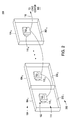
- Figure 2 is a block diagram depicting a physical layout of the system of Figure 1 in accordance with one or more embodiments of the present invention
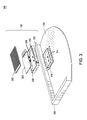
- Figure 3 depicts a perspective, exploded view of an assembly for mounting an inverter to a PV module in accordance with one or more embodiments of the present invention
- Figure 4 is an exploded, close-up view of an assembly for mounting an inverter to a PV module in accordance with one or more embodiments of the present invention
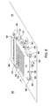
- Figure 5 is an exploded, close-up view of an alternative assembly for mounting an inverter to a PV module in accordance with one or more embodiments of the present invention
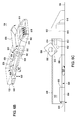
- Figures 6A-6C depict a plurality of perspective views of another alternative assembly for mounting an inverter to a PV module in accordance with one or more embodiments of the present invention
- Figure 7 is a schematic diagram of a DC connection assembly in accordance with one or more embodiments of the present invention.
- Figure 8 is a side-angled perspective view depicting a horizontal sliding technique for coupling an inverter to a universal connector assembly in accordance with one or more embodiments of the present invention
- Figure 9 is a side perspective view depicting a pivoting technique for coupling an inverter to a universal connector assembly in accordance with one or more embodiments of the present invention.
- Figure 10 is a side perspective view depicting a top insert technique for coupling an inverter to a universal connector assembly in accordance with one or more embodiments of the present invention.
- FIG. 1 is a block diagram of a photovoltaic (PV) system 100 for generating power in accordance with one or more embodiments of the present invention. This diagram only portrays one variation of the myriad of possible system configurations. The present invention can function in a variety of environments and systems.
- PV photovoltaic
- the PV system 100 comprises a plurality of power modules 102 1 , 102 2 ... 102 n (collectively power modules 102), a plurality of PV modules 104 1 , 104 2. .. 104 n (collectively PV modules 104), and a plurality of universal connector assemblies 110 1 , 110 2 ... 110 n (collectively PV modules 110).
- the power modules 102 are DC/AC inverters, referred to as inverters 102, for inverting DC power generated by the PV modules 104 to AC power (i.e., AC current).
- the power modules 102 may be DC junction boxes or DC/DC converters.
- each inverter 102 1 , 102 2 ... 102 n is individually coupled to a PV module 104 1, 104 2 . .. 104 n , respectively, via a universal connector assembly 110 1 , 110 2 ... 110 n , respectively, in a one-to-one correspondence.
- the universal connector assemblies 110 mechanically mount the inverters 102 to the PV modules 104; in some embodiments, the universal connector assemblies 110 removably mount the inverters 102 to the PV modules 104 such that the inverters 102 may be removed from and/or coupled to the PV modules 104, for example, in a field environment. Additionally, the universal connector assemblies 110 may electrically couple the inverters 102 to the PV modules 104 for providing the DC power from the PV modules 104 to the inverters 102.
- the inverters 102 are further coupled to an AC bus 106, which in turn is coupled to a load center 108, for providing the AC output power produced by the inverters 102.
- the load center 108 houses connections between incoming power lines from a commercial power grid distribution system and the AC bus 106.
- the inverters 102 meter out AC current that is in-phase with the AC commercial power grid voltage, and the system 100 couples the generated AC power to the commercial power grid via the load center 108. Additionally or alternatively, the generated AC power may be supplied directly to commercial and/or residential systems via the load center 108.
- a DC junction box may be coupled to each PV module 104 via a universal connector assembly 110 (i.e., one DC junction box per PV module 104) in addition to or in place of the inverters 102.
- a DC/DC converter may be coupled to each PV module 104 via a universal connector assembly 110 (i.e., one converter per universal connector assembly 110).
- the universal connector assemblies 110 thereby provide a standardized means for efficiently coupling any compatible power component, e.g., a DC junction box, a DC/DC converter, or a DC/AC inverter, to a PV module, thereby providing a modular plug-n-play system that facilitates flexible solar power system design and fabrication as well as maintenance and repair.
- FIG. 2 is a block diagram depicting a physical layout of the PV system 100 in accordance with one or more embodiments of the present invention.
- Each PV module 104 1 , 104 2 ... 104 n comprises a structural frame 202 1 , 202 2 ... 202 n , respectively, collectively referred to as frames 202.
- Each of the frames 202 surrounds the perimeter of the corresponding PV module 104 and may be constructed of any rigid material, such as aluminum, rigid plastic, and the like, or any combination of such rigid materials.
- the frames 202 of the PV modules 104 are generally coupled flush with the frames 202 of neighboring PV modules 104 in a horizontal direction.
- the inverters 102 1 , 102 2 ... 102 n are coupled to the universal connector assemblies 110 1 , 110 2 ... 110 n , respectively, in a one-to-one correspondence, and the universal connector assemblies 110 1 , 110 2 ... 110 n are further coupled to the PV modules 104 1 , 104 2 ... 104 n , also in a one-to-one correspondence.
- the universal connector assemblies 110 provide a mechanism for mechanically coupling (i.e., mounting) the inverters 102 to the PV modules 104; in some embodiments, such coupling may be performed in a removable fashion.
- the universal connector assemblies 110 secure the inverters 102 proximate (i.e., spaced apart from) the rear face of the PV modules 104 (i.e., the side to face away from the sun) such that each of the inverters 102 may be electrically coupled to the corresponding PV module 104 for inverting the generated DC power to AC power.
- the universal connector assemblies 110 themselves provide the electrical connectivity between the inverters 102 and the PV modules 104.
- a DC junction box may be coupled between each PV module 104 and each inverter 102 for providing DC connections between the PV module 104 and the corresponding inverter 102.
- the AC power at the output of the inverters 102 is coupled to the AC bus 106 for providing such AC power to the load center 108 for further distribution.
- FIG. 3 depicts a perspective, exploded view of an assembly 300 for mounting an inverter 102 to a PV module 104 in accordance with one or more embodiments of the present invention.
- the PV module 104 comprises a set of two DC contacts 314 (i.e., a positive and a negative contact) for providing a DC current output from the PV module 104.
- the DC contacts 314 may consist of two exposed conductor ribbons (sometimes referred to as foil) from the PV module 104; alternatively, the DC contacts 314 may be part of an existing DC junction box of the PV module 104 or a DC/DC converter.
- the universal connector assembly 110 may be in the form of a retaining ring 316.
- the retaining ring 316 is a hollow supporting base comprising a flange that extends around at least a portion of the retaining ring perimeter for adhering the retaining ring 316 to the rear face of the PV module 104.
- the retaining ring 316 is of a size and shape, such as oval, round, square, rectangular, or the like, that can support the inverter 102 proximate but spaced apart from the PV module 104, and may be constructed of any rigid insulating material such as dielectric plastic or the like.
- the retaining ring 316 may be mounted to the PV module 104 by adhering the flange to the PV module rear face, for example by epoxy, bonding, VHBTM (Very High Bond) tape, or similar mechanical method, such that the DC contacts 314 are exposed within the perimeter of the retaining ring 316.
- the retaining ring 316 may be adhered to the PV module 104 by a mechanism that provides immediate secure adhesion, such as VHBTM tape, and further sealed by an applied or dispensed adhesive or sealant such as epoxy or silicone, thereby allowing the integrated PV module 104/inverter 102 to be moved immediately following assembly without any wait time.
- the inverter 102 is comprised of a casing 308, an inverter board 304, and a casing cover 302.
- the casing 308 and casing cover 302 may be constructed from any rigid material, such as metal, plastic, and the like, and house the inverter board 304 which comprises the inverter electronics.
- the casing cover 302 encloses the inverter board 304 within the casing 308 and may be secured to the casing 308 by one or more of screws, bolts, bonding adhesives, snap features, clips, or similar mechanical means. Additionally, one or more connectors may be provided as part of the inverter board 304 and/or the casing 308 for grounding and/or coupling the AC power from the inverter 102.
- the casing cover 302 may comprise a heat sink, for example protruding combs, ribs, and/or fins that are part of the form factor of the casing cover 302; alternatively, the heat sink may be coupled to the casing cover 302.
- a heat sink for example protruding combs, ribs, and/or fins that are part of the form factor of the casing cover 302; alternatively, the heat sink may be coupled to the casing cover 302.
- the inverter board 304 comprises two conductive DC connectivity pins 306 consisting of a conductive material such as aluminum, copper, and the like, for coupling to the positive and negative DC contacts 314.
- the DC connectivity pins 306 protrude from the inverter board 304 and extend through one or more apertures in the casing 308, such as a set of two pin apertures 310.
- the DC connectivity pins 306 may utilize a spring-mechanism type of contact, such as a leaf spring, or similar resilient contact, for making contact with the DC contacts 314; alternatively, the DC connectivity pins 306 may be electrically coupled to the DC contacts 314 via a socketed contact.
- the form factor of the casing 308 comprises a coupling surface 312 for coupling the casing 308 to the retaining ring 316; in alternative embodiments, the coupling surface 312 may be a separate component coupled to the casing 308.
- the coupling surface 312 is of a size and shape such that it mates with the retaining ring 316 and provides an environmental seal to protect the enclosed electrical connections (i.e., the electrical connections between the DC contacts 314 and the DC connectivity pins 306) from environmental factors and foreign matter.
- An O-ring may be utilized to provide an additional environmental seal, and/or the interior of the retaining ring 316 may be encapsulated (e.g., silicone filled) such that the DC contacts 314 remain accessible.
- the coupling surface 312 may be secured to the retaining ring 316 by a detachable mechanical method, such as one or more of snap features, clips, screws, rivets and the like; additionally and/or alternatively, the coupling surface 312 may be permanently secured to the retaining ring 316, for example by bonding adhesives.
- the retaining ring 316 is of a size and shape such that the inverter 102 is retained a suitable distance from PV module 104 to provide a thermal barrier between the inverter 102 and the PV module 104. Such a thermal barrier reduces thermal contact between the inverter 102 and the PV module 104 and allows a uniform thermal profile to be maintained across temperature-sensitive PV cells of the PV module 104. Additionally, the retaining ring flange is of a size that minimizes thermal effects when adhered to the PV module 104. The retaining ring 316 may maintain the inverter 102 within the plane of the PV module frame 202; alternatively, the inverter 102 may be extended beyond the PV module frame plane.
- FIG. 4 is an exploded, close-up view of an assembly 400 for mounting an inverter 102 to a PV module 104 in accordance with one or more embodiments of the present invention.
- the retaining ring 316 is adhered to the rear face of the PV module 104 by a method as previously described, such that the DC contacts 314 are exposed within the retaining ring perimeter.
- An O-ring 402 is aligned within the perimeter of the retaining ring 316 such that the DC contacts 314 remain exposed, and the O-ring 402 may be additionally secured by an adhesive, such as a silicone adhesive or a similar epoxy.
- the coupling surface 312 of the casing 308 is coupled to the retaining ring 316, and the inverter board 304 is retained between the casing 308 and the casing cover 302 as previously described.
- the DC connectivity pins 306 of the inverter board 304 are aligned with and pass through the pin apertures 310 of the casing 312 and are electrically coupled to the DC contacts 314.
- the DC connectivity pins 306 may make direct contact with the DC contacts 314, for example by a resilient contact, such as a spring-mechanism, or a socketed connection.
- an optional DC junction box 404 may be coupled between the inverter 102 and the PV module 104.
- the DC junction box 404 may be an existing component of the PV module 104 that presents the DC contacts 314 to the inverter 102.
- the DC junction box 404 may be retained between the retaining ring 316 and the inverter 102.
- the DC junction box 404 may be coupled to the DC contacts 314 and present a separate set of DC contacts to the DC connectivity pins 306.
- the DC junction box 404 may be removeably coupled to the retaining ring 316 by a mechanical means such as one or more of snap features, clips, screws, rivets and the like, and/or may be permanently adhered to the retaining ring 316 by means such as epoxy, bonding, and the like.
- the retaining ring 316 allows the inverter 102 and the PV module 104 to be physically coupled/decoupled as needed, for example in a manufacturing environment and/or in a field environment, thereby facilitating flexible solar power system design and fabrication as well as maintenance and repair.
- FIG. 5 is an exploded, close-up view of an alternative assembly 500 for mounting an inverter 102 to a PV module 104 in accordance with one or more embodiments of the present invention.
- the universal connector assembly 110 may comprise a retaining base 502 having an X-shaped support 520 contained within a rectangular or oval perimeter 522.
- the retaining base 502 is adhered to the rear face of the PV module 104 by an adhesive such as glue, VHBTM tape, or similar substance.
- the entire retaining base 502, including the X-shaped support 520 and the perimeter 522, may be adhered to the PV module 104; alternatively, one or more portions of the retaining base 502, such as "feet" 524 located at corners of the retaining base perimeter 522, may be adhered to the PV module 104, to allow air circulation between the retaining base 502 and the PV module 104.
- the retaining base 502 may be constructed from any rigid insulating material, such as dielectric plastic and the like, and is functionally analogous to the retaining ring 316 for mounting the inverter 102 proximate the PV module 104.
- the DC contacts 314 of the PV module 104 are coupled to conductive leads 504 of the retaining base 502.
- the retaining base 502 may comprise two conductive leads 504 formed of a conductive material (e.g., aluminum, copper, or the like) that are coupled to the DC contacts 314 by welding, soldering, or similar method; alternatively, the conductive leads 504 may be coupled to the DC contacts 314 by a quick-connect method utilizing a resilient contact, such as a spring-connector mechanism.
- An optional diode 506 may be coupled between the conductive leads 504 by a method such as welding, soldering, quick-connect method, or similar method.
- the retaining base 502 defines a shallow well 508 at the center of the X-shaped support 520, within which the conductive leads 504 reside.
- the well 508, including the conductive leads 504 coupled to the DC contacts 314 and optionally the diode 506, may be encapsulated by a potting material, such as polyurethane, silicon, or similar substance having limited moisture absorption properties, for sealing and protecting the electrical connections between the DC contacts 314 and the conductive leads 504 from environmental factors and foreign matter.
- the retaining base 502 further comprises a retaining flange 510 for coupling to the inverter 102.
- the inverter 102 comprises a casing 514, analogous to the casing 308, where the casing 514 comprises an aperture rimmed by a flange extending towards the interior of the casing 514.
- the flange is generally part of the form factor of the casing 514 although may, in some embodiments, be coupled to the casing 514.
- the casing flange provides a coupling surface 516 of a size and shape for mating to the retaining flange 510 to secure the casing 514 to the retaining base 502.
- the coupling surface 516 may be secured to the retaining flange 514 by a detachable mechanical method, such as one or more of snap features, clips, screws, rivets and the like; additionally or alternatively, the coupling surface 516 may be permanently secured to the retaining flange 514, for example by bonding adhesives.
- An O-ring 512 may be utilized to provide an additional environmental seal and may be secured by an adhesive, such as a silicone adhesive or a similar epoxy.
- the casing cover 302 encloses the inverter board 304 within the casing 514 and may be secured to the casing 514 by one or more of screws, bolts, bonding adhesives, snap features, clips, or similar mechanical means.
- a DC junction box such as the DC junction box 404, may be removeably coupled to the retaining base 502/retaining flange 510 by a mechanical means, such as one or more of snap features, clips, screws, rivets and the like, and/or may be permanently adhered to the retaining base 502 by means such as epoxy, bonding, and the like.
- the DC junction box may be coupled between the inverter 102 and the PV module 104.
- Figures 6A-6C depict a plurality of perspective views of another alternative assembly 600 for mounting an inverter 102 to a PV module 104 in accordance with one or more embodiments of the present invention.
- the assembly 600 may mount a DC junction box or a DC/DC converter to the PV module 104.
- Figures 6A , 6B, and 6C provide an overhead perspective view, a side-angled perspective view, and a side perspective view, respectively, of the assembly 600.
- the universal connector assembly 110 comprises a connector housing 602 coupled to a base 604, each formed of a rigid insulating material, such as dielectric plastic or the like.
- the connector housing 602 is generally a rectangular shape having a width on the order of the inverter width, and is mounted on the rear face of the PV module 104 for mechanically as well as electrically coupling the inverter 102 to the PV module 104.
- the connector housing 602 generally has a height such that the inverter 102, once coupled to connector housing 602, is generally flush with the top of the connector housing 602.
- the connector housing 602 is adhered to the rear face of the PV module 104 by any of the methods previously described such that PV module DC contacts 618 are exposed within a well 614 defined by the connector housing 602.
- the PV module DC contacts 618 generally comprise four foil or ribbon contacts extending from the rear face of the PV module 104 for providing DC current produced by the PV module 104.
- the well 614 exposes the PV module DC contacts 618 subsequent to the connector housing 602 being adhered to the PV module 104, thereby allowing the PV module DC contacts 618 be coupled to a DC connection assembly 616 of the connector housing 602.
- the PV module DC contacts 618 may be soldered, welded, clamped, screwed, and/or similarly coupled to the DC connection assembly 616 such that the PV module DC contacts 618 maintain electrical connectivity with the DC connection assembly 616.
- the well 614 may subsequently be sealed by a cover and/or encapsulated with a non-conductive potting material having limited moisture absorption properties, such as silicone, polyurethane, or the like, for protecting the electrical connections between the PV model 104 and the DC connection assembly 616 from environmental factors and foreign matter.
- the DC connection assembly 616 comprises output connectors 612 1 , 612 2 , 612 3 , and 612 4 (collectively “output connectors 612") that mate with inverter connectors 634 1 , 634 2 , 634 3 , and 634 4 (collectively "inverter connectors 634"), respectively; in some alternative embodiments, fewer or more connectors may be utilized.
- the output connectors 612 couple DC power (i.e., DC current) generated by the PV module 104 to the inverter 102; additionally, in some embodiments, the output connectors 612 couple a unique PV module identifier to the inverter 102, as described in more detail with respect to Figure 7 .
- the output connectors 612 and the inverter connectors 634 are pin-type connectors and socket-type connectors, respectively.
- the output connectors 612 extend horizontally, with respect to the PV module face, from a vertical edge of the connector housing 602 along which the inverter 102 will be mounted, while the inverter connectors 634 are disposed along a side of the inverter 102 for mating with the output connectors 612.
- the output connectors 612 and/or the inverter connectors 634 may be other types of compatible connectors, such as socket, spring, leaf, or the like. Additionally or alternatively, the output connectors 612 and/or the inverter connectors 634 may be positioned differently on the universal connector assembly 110 and inverter 102.
- the connector housing 602 may comprise flanges 626, for example, horizontally disposed from each side of the connector housing 602, for aligning the inverter 102 with the universal connector assembly 110 during insertion and for subsequently supporting the mounted inverter 102.
- the base 604 generally has an inverted Y-shape with respect to the connector housing 602, although different shapes may be utilized, and is adhered to the rear face of the PV module 104 analogous to the connector housing 602.
- the base 604 is of a length, width, and thickness for supporting the inverter 102 at a spacing 622 from the PV module face, while simultaneously exposing at least a portion of the inverter 102 facing the PV module 104 and maintaining a minimum footprint on the face of the PV module 104.
- the base 604 may comprise "feet" along the outer edges of the prongs of the Y-shape that are adhered to the PV module 104; alternatively, one or more other portions of the base 604, or the entire base 604, may be adhered to the PV module face.
- the spacing 622, as well as the shape of the base 604, ensure an airflow 624 may be circulated between the inverter 102 and the PV module 104 for maintaining a suitable thermal profile across the PV module cells as well as the inverter 102.
- the outer edges of the base 604 may comprise flanges 608, disposed vertically with respect to the PV module face, for aligning the inverter 102 with the universal connector assembly 110 during insertion and for subsequently supporting the mounted inverter 102.
- the universal connector assembly 110 may further comprise a safety latch 606 in the form of an elongated U-shaped bar or bracket, for example, that pivots about hinges 610 for securing the mounted inverter 102.
- the safety latch 606 may be hinged to the flanges 626 and pivot toward the connector housing 602 when moved from an open to a closed position to secure the inverter 102; alternatively, the safety latch 606 may be hinged to the body of the connector housing 602 and pivot away from the connector housing 602 when moved from open to closed to secure the inverter 102.
- the latch 602 may comprise one or more fasteners, such as a lock, clasp, hook, snap features, or the like, for locking the latch 602 in place once it is closed. Additionally, the latch 602 may comprise a puller/ejector mechanism for tightly coupling the inverter 102 to the universal connector assembly 110 during insertion and for ejecting the inverter 102 from the universal connector assembly 110 during removal.
- fasteners such as a lock, clasp, hook, snap features, or the like
- the safety latch 606 comprises an orifice 620 along one side which, when the safety latch 606 is in a closed position, exposes an output power connector 632 of the inverter 102, i.e., a connector for coupling output power from the inverter 102.
- an output power connector 632 of the inverter 102 i.e., a connector for coupling output power from the inverter 102.
- electrical connectivity between the inverter 102 and the DC connection assembly 616 may not be complete until the safety latch 606 is in the closed position; i.e., closing the safety latch 606 activates the puller mechanism to tightly couple the inverter connectors 634 to the output connectors 612 for completing the electrical connection.
- the inverter 102 comprises a heat sink 628 having a plurality of comb-like structures, external ribs, fins, or the like, for dissipating heat generated by the inverter 102.
- the heat sink 628 may be formed from any rigid, thermally conducting material, such as plastic, metal, or the like; in some embodiments, the heat sink 628 may be formed from black anodized metal, such as black anodized aluminum, for improved heat dissipation.
- the heat sink 628 may be attached to the inverter 102 by one or more of screws, bolts, bonding adhesives, snap features, clips, or similar mechanical means; alternatively, the heat sink 628 may be part of the inverter form factor.
- the inverter 102 may further comprise an inverter base 630 having a reflective surface for facing the PV module 104 to reflect heat radiated by the PV module cells.
- the reflective surface may be formed from a polished stainless steel, reflective glass, or similar shiny material, and may be adhered to the inverter 102 or part of the inverter form factor.
- the universal connector assembly 110 and/or the inverter 102 may be adapted for utilizing any of a plurality of possible insertion techniques for inserting the inverter 102 into the universal connector assembly 110 (i.e., for coupling the inverter 102 to the universal connector assembly 110).
- Such techniques include horizontally sliding the inverter 102 along the base 604, for example utilizing a guiding track to properly align the inverter connectors 634 with the output connectors 612; positioning the inverter 102 at an angle with respect to the universal connector assembly 110 to marry the inverter connectors 634 and the output connectors 612, and subsequently pivoting the inverter 102 downward toward the base 604 to secure the inverter 102 to the universal connector assembly 110; or, in some alternative embodiments where the output connectors 612 are disposed along a horizontal face of the connector housing 602, vertically aligning the inverter 102 with the universal connector assembly 110 and pressing the inverter 102 downward toward the base 604 to secure the inverter 102 to the universal connector assembly 110.
- Such techniques are described in more detail with respect to Figures 8 , 9, and 10 .
- the inverter 102 may be secured by one or more mechanical means in addition to or in place of those previously described, such as snap-fit, latching clips, screws, straps, or the like.
- FIG. 7 is a schematic diagram of a DC connection assembly 616 in accordance with one or more embodiments of the present invention.
- the DC connection assembly 616 comprises connectors 704 1 , 704 2 , 704 3 , 704 4 (collectively connectors 704) for electrically coupling to the PV module DC connectors 618 1 , 618 2 , 618 3 , and 618 4 (collectively PV module DC connectors 618), respectively.
- the connectors 704 may be any type of connector suitable for being electrically coupled to the PV module DC connectors 618, such as pin-out slots, sockets, clamps, leaf springs, or the like, and may be soldered, screwed, clamped, or similarly coupled to the PV module DC connectors 618.
- the connectors 704 1 and 704 4 are further electrically coupled to output connectors 612 1 and 612 4 , respectively, for providing the DC current output from the PV module 104 to the inverter 102.
- the DC connection assembly 616 comprises diodes 706 1 , 706 2 , and 706 3 (collectively diodes 706) coupled between connectors 704 1 /704 2 , 704 2 /704 3 , and 704 3 /704 4 , respectively, for providing a bypass function to prevent reverse-current damage to the PV cells of the PV module 104.
- diodes 706 are shown in Figure 7 , a different number of diodes may be utilized based on the number of PV module DC connectors 704.
- active semiconductor components other than diodes, may be utilized to provide the bypass function.
- the DC connection assembly 616 also provides a means for individually identifying each PV module 104.
- the DC connection assembly 616 comprises a memory 702 for storing a unique PV module identification (ID) number, such as a serial number.
- ID unique PV module identification
- the memory 702 is a static two-conductor memory that is pre-programmed with the PV module ID; in some alternative embodiments, other types of memory structures may be utilized for storing the PV module ID.
- the memory 702 is coupled to output connectors 612 2 and 612 3 for providing the PV module ID to the inverter 102.
- the inverter 102 may then store and/or communicate the PV module ID to a centralized system for tracking the corresponding PV module 104.
- a PV module ID is further described in commonly assigned U.S. Patent Application Serial No. 61/270,809 , entitled “Method and System for Locating Stolen Solar Power System Components” and filed July 14, 2009.
- Figure 8 is a side-angled perspective view depicting a horizontal sliding technique for coupling an inverter 102 to a universal connector assembly 110 in accordance with one or more embodiments of the present invention.
- a connector housing 602 and a base 604 of the universal connector assembly 110 are adhered to a PV module 104 as previously described.
- the base 630 protrudes due to one or more flanges 802 extending horizontally from each side of the inverter 102 along the length of the inverter 102.
- flanges 608 and 626 each have a form of an inverted L-shape such that the flanges 802 may be inserted into the flanges 608 and 626 and the inverter 102 then horizontally slid toward the connector housing 602.
- the flanges 608 and 626 act as a track for guiding the inverter 102 during insertion into the universal connection assembly to ensure that the output connectors 612 and the inverter connectors 634 are properly aligned prior to contact.
- the inverter 102 and/or the universal connector assembly 110 may employ additional and/or alternative flanges, flange shapes, and/or similar guide/track structures to ensure proper alignment when the inverter 102 is inserted into the universal connector assembly 110 by the horizontal sliding technique.
- the safety latch 606 may comprise a puller/ejector that may be engaged when the inverter 102 is coupled to/removed from the universal connector assembly 110 by the horizontal sliding technique.
- the safety latch 606 may be moved from an open position to a closed position after the inverter 102 is inserted into the universal connector assembly 110 as previously described.
- the puller mechanism is engaged and draws the inverter 102 toward the connector housing 602 to tightly couple the inverter connectors 634 to the output connectors 612.
- the orifice 620 exposes the connector 632.
- the orifice 620 which may alternatively be referred to as a power output connector interface of the safety latch 606, ensures that the inverter 102 cannot be removed from the universal connector assembly 110 while having an output coupled to the connector 632.
- the safety latch 606 When the inverter 102 is to be removed from the universal connector assembly 110, the safety latch 606 is moved from the closed to the open position, engaging the ejector mechanism to eject the inverter 102 from the universal connector assembly 110.
- the ejector may release the connection between the inverter connectors 634 and the output connectors 612 so that the inverter 102 may be horizontally slide away from the connector housing 602 and removed from the universal connector assembly 110.
- the inverter 102 While the inverter 102 is coupled to the universal connector assembly 110, the inverter 102 is retained at the spacing 622 from the face of the PV module 104, thereby ensuring the airflow 624 can circulate between the inverter 102 and the PV module 104 to maintain a suitable thermal profile across the PM module PV cells as well as the inverter 102.
- Figure 9 is a side perspective view depicting a pivoting technique for coupling an inverter 102 to a universal connector assembly 110 in accordance with one or more embodiments of the present invention.
- a connector housing 602 and a base 604 of the universal connector assembly 110 are adhered to a PV module 104 as previously described.
- the output connectors 612 are pin-type connectors where the free end of each pin (i.e., the end of the pin not coupled to the connector housing 602) comprises a protrusion 908, such as a bulbous shape.
- the inverter connectors 634 are socket-type connectors or receptacles for mating with the output connectors 612.
- Each inverter connector 634 comprises a conductive pad 904 opposing a detent 906.
- the inverter 102 is inserted into the universal connector assembly 110 at an angle such that the output connectors 612 are received into the inverter connectors 634.
- the inverter 102 is subsequently rotated toward the base 604, utilizing a cam action to cause the detent 906 to apply and maintain pressure against the output connectors 612 for connectively coupling the protrusion 908 to the conductive pad 904.
- other types of cam action may be utilized for connectively coupling the inverter connectors 634 to the output connectors 612.
- the safety latch 606 coupled to connector housing 602 by hinges 610, may be rotated toward the inverter 102 to secure the inverter 102 in place and expose the connector 632 through the orifice 620 while the safety latch 606 is in the closed position, thereby ensuring that the inverter 102 cannot be removed from the universal connector assembly 110 while having an output coupled to the connector 632.
- the safety latch 606 may comprise a puller/ejector for tightly coupling the inverter 102 to the universal connector assembly 110 when moved from the open to the closed position and ejecting the inverter 102 from the universal connector assembly 110 when moved from the closed to the open position, as previously described.
- the universal connector assembly 110 retains the inverter 102 at the spacing 622 from the face of the PV module 104, thereby ensuring the airflow 624 may circulate between the inverter 102 and the PV module 104 to maintain a suitable thermal profile across the PM module PV cells as well as the inverter 102. Additionally, the heat sink 628 dissipates heat generated by the inverter 102.
- Figure 10 is a side perspective view depicting a top insert technique for coupling an inverter 102 to a universal connector assembly 110 in accordance with one or more embodiments of the present invention.
- a connector housing 602 and a base 604 of the universal connector assembly 110 are adhered to a PV module 104 as previously described.
- the output connectors 612 are vertically disposed with respect to the PV module 104 (i.e., perpendicular to the PV module face).
- the inverter connectors 634 are disposed on the inverter base 630 such that the inverter 102 may be aligned with the universal connector assembly 110 from an overhead position and pushed downward toward the base 604 to electrically and mechanically couple the inverter 102 to the universal connector assembly 110.
- one or more mechanical means such as snap-fit, latching clips, screws, straps, or the like, may be utilized to secure the inverter 102 to the universal connector assembly 110.
- the safety latch 606 coupled to connector housing 602 by hinges 610, may be rotated toward the inverter 102 to secure the inverter 102 in place and expose the connector 632 through the orifice 620 while the safety latch 606 is in the closed position, thereby ensuring that the inverter 102 cannot be removed from the universal connector assembly 110 while having an output coupled to the connector 632.
- the safety latch 606 may comprise a puller/ejector for tightly coupling the inverter 102 to the universal connector assembly 110 when moved from the open to the closed position and ejecting the inverter 102 from the universal connector assembly 110 when moved from the closed to the open position, as previously described
- the universal connector assembly 110 retains the inverter 102 at the spacing 622 from the face of the PV module 104, thereby ensuring the airflow 624 between the inverter 102 and the PV module 102 for maintaining a suitable thermal profile across the PM module PV cells as well as the inverter 102. Additionally, the heat sink 628 dissipates heat generated by the inverter 102.
- the universal connector assembly 110 presents a universal interface for mechanically and electrically coupling a plurality of types of power modules, such as a DC junction box, a DC/DC converter, or a DC/AC inverter, to a PV module, thereby making possible a standardization such that any compatible power module may be efficiently coupled to the PV module in a factory and/or field environment. Additionally, the universal connector assembly 110 couples power from the PV module 104 to the power element by a minimum number of connection points, i.e., one connection point between the PV module DC connectors 618 and the DC connection assembly 616, and one connection point between the DC connection assembly 616 and the power module, for optimal reliability.
- a minimum number of connection points i.e., one connection point between the PV module DC connectors 618 and the DC connection assembly 616, and one connection point between the DC connection assembly 616 and the power module, for optimal reliability.
Landscapes
- Inverter Devices (AREA)
- Connector Housings Or Holding Contact Members (AREA)
- Photovoltaic Devices (AREA)
- Charge And Discharge Circuits For Batteries Or The Like (AREA)
Abstract
Apparatus for coupling power generated by a photovoltaic (PV) module (1041; 1042;...; 104n) to an output. The apparatus comprises a universal connector assembly (1101; 1102;...; 110n), comprising a connector housing (602), adapted for coupling to the PV module, comprising means for coupling power from the PV module to a power module via a first plurality of connectors; and means for supporting the power module spaced apart from the PV module in a manner that exposes at least a portion of the power module facing the PV module to air and prevents the air from being trapped between the power module and the PV module, wherein the power module is a DC junction box, a DC/DC converter, or a DC/AC inverter.
Description
- Embodiments of the present disclosure generally relate to inverters and, more particularly, to an apparatus for coupling an inverter to a photovoltaic module. In particular, the present disclosure relates to an apparatus for coupling power generated by a photovoltaic module to an output. Further, the present disclosure relates to a system for coupling a power module to a photovoltaic module.
- Solar panels have historically been deployed in mostly remote applications, such as remote cabins in the wilderness or satellites, where commercial power was not available. Due to the high cost of installation, solar panels were not an economical choice for generating power unless no other power options were available. However, the worldwide growth of energy demand is leading to a durable increase in energy cost. In addition, it is now well established that the fossil energy reserves currently being used to generate electricity are rapidly being depleted. These growing impediments to conventional commercial power generation make solar panels a more attractive option to pursue.
- Solar panels, or photovoltaic (PV) modules, convert energy from sunlight received into direct current (DC). The PV modules cannot store the electrical energy they produce, so the energy must either be dispersed to an energy storage system, such as a battery or pumped hydroelectricity storage, or dispersed by a load, for example by providing alternating current (AC) to business or residential buildings or coupling AC power to a commercial power grid. In some solar power systems that provide AC power, PV modules may be coupled to inverters that invert the DC current to AC current in a distributed architecture; i.e., one inverter per PV module. For such solar power systems, installation generally involves mechanically attaching the inverters to a rigid mounting rail, coupling each inverter to an individual PV module, and mechanically attaching the PV modules to the mounting rail. This installation process is complex as well as labor and time intensive.
- Therefore, there is a need in the art for an apparatus to efficiently couple an inverter to a PV module.
- The problems are at least partially solved by the subject-matter of the independent claims. Further details, aspects, and embodiments are evident from the dependent claims, the detailed description, and the accompanying drawings.
- Embodiments of the present invention generally relate to an apparatus for coupling power generated by a photovoltaic (PV) module to an output. The apparatus comprises a universal connector assembly, comprising a connector housing, adapted for coupling to the PV module, comprising means for coupling power from the PV module to a power module via a first plurality of connectors; and means for supporting the power module spaced apart from the PV module in a manner that exposes at least a portion of the power module facing the PV module to air and prevents the air from being trapped between the power module and the PV module, wherein the power module is a DC junction box, a DC/DC converter, or a DC/AC inverter.
- According to further aspects, a system for coupling a power module to a photovoltaic (PV) module is provided. The system includes a universal connector assembly, wherein the universal connection assembly is adapted for interchangeably accepting a DC junction box, a DC/DC converter, or a DC/AC inverter.
- The universal connection assembly is adapted for electrically and mechanically coupling the DC junction box, the DC/DC converter, or the DC/AC inverter to the PV module.
- Alternatively, the universal connector assembly includes a connector housing, adapted for coupling to the PV module, for coupling power from the PV module to the power module; a base, extending from the connector housing, for supporting the power module; and a safety latch, coupled to the connector housing, for retaining the power module when the power module is coupled to the universal connector assembly and comprising a power output connector interface for ensuring the power module cannot be removed from the universal connector assembly while having a power output connector connected.
- The invention is also directed to an apparatus for carrying out the disclosed methods and including apparatus parts for performing each described method steps. These method steps may be performed by way of hardware components, a computer programmed by appropriate software, by any combination of the two or in any other manner. Furthermore, the invention is also directed to methods by which the described apparatus operates. It includes method steps for carrying out every function of the apparatus.
- So that the manner in which the above recited features of the present invention can be understood in detail, a more particular description of the invention, briefly summarized above, may be had by reference to embodiments, some of which are illustrated in the appended drawings. It is to be noted, however, that the appended drawings illustrate only typical embodiments of this invention and are therefore not to be considered limiting of its scope, for the invention may admit to other equally effective embodiments.
-
Figure 1 is a block diagram of a system for inverting solar generated DC power to AC power in accordance with one or more embodiments of the present invention; -
Figure 2 is a block diagram depicting a physical layout of the system ofFigure 1 in accordance with one or more embodiments of the present invention; -
Figure 3 depicts a perspective, exploded view of an assembly for mounting an inverter to a PV module in accordance with one or more embodiments of the present invention; -
Figure 4 is an exploded, close-up view of an assembly for mounting an inverter to a PV module in accordance with one or more embodiments of the present invention; -
Figure 5 is an exploded, close-up view of an alternative assembly for mounting an inverter to a PV module in accordance with one or more embodiments of the present invention; -
Figures 6A-6C depict a plurality of perspective views of another alternative assembly for mounting an inverter to a PV module in accordance with one or more embodiments of the present invention; -
Figure 7 is a schematic diagram of a DC connection assembly in accordance with one or more embodiments of the present invention; -
Figure 8 is a side-angled perspective view depicting a horizontal sliding technique for coupling an inverter to a universal connector assembly in accordance with one or more embodiments of the present invention; -
Figure 9 is a side perspective view depicting a pivoting technique for coupling an inverter to a universal connector assembly in accordance with one or more embodiments of the present invention; and -
Figure 10 is a side perspective view depicting a top insert technique for coupling an inverter to a universal connector assembly in accordance with one or more embodiments of the present invention. -
Figure 1 is a block diagram of a photovoltaic (PV) system 100 for generating power in accordance with one or more embodiments of the present invention. This diagram only portrays one variation of the myriad of possible system configurations. The present invention can function in a variety of environments and systems. - The PV system 100 comprises a plurality of
power modules PV modules universal connector assemblies power modules 102 are DC/AC inverters, referred to asinverters 102, for inverting DC power generated by thePV modules 104 to AC power (i.e., AC current). In other embodiments, thepower modules 102 may be DC junction boxes or DC/DC converters. - In accordance with one or more embodiments of the present invention, each
inverter PV module 1041, 1042. .. 104n, respectively, via auniversal connector assembly inverters 102 to thePV modules 104; in some embodiments, the universal connector assemblies 110 removably mount theinverters 102 to thePV modules 104 such that theinverters 102 may be removed from and/or coupled to thePV modules 104, for example, in a field environment. Additionally, the universal connector assemblies 110 may electrically couple theinverters 102 to thePV modules 104 for providing the DC power from thePV modules 104 to theinverters 102. - The
inverters 102 are further coupled to anAC bus 106, which in turn is coupled to aload center 108, for providing the AC output power produced by theinverters 102. In some embodiments, theload center 108 houses connections between incoming power lines from a commercial power grid distribution system and theAC bus 106. In such embodiments, theinverters 102 meter out AC current that is in-phase with the AC commercial power grid voltage, and the system 100 couples the generated AC power to the commercial power grid via theload center 108. Additionally or alternatively, the generated AC power may be supplied directly to commercial and/or residential systems via theload center 108. - In some embodiments, a DC junction box may be coupled to each
PV module 104 via a universal connector assembly 110 (i.e., one DC junction box per PV module 104) in addition to or in place of theinverters 102. Additionally or alternatively, a DC/DC converter may be coupled to eachPV module 104 via a universal connector assembly 110 (i.e., one converter per universal connector assembly 110). Theuniversal connector assemblies 110 thereby provide a standardized means for efficiently coupling any compatible power component, e.g., a DC junction box, a DC/DC converter, or a DC/AC inverter, to a PV module, thereby providing a modular plug-n-play system that facilitates flexible solar power system design and fabrication as well as maintenance and repair. -
Figure 2 is a block diagram depicting a physical layout of the PV system 100 in accordance with one or more embodiments of the present invention. EachPV module structural frame frames 202. Each of theframes 202 surrounds the perimeter of thecorresponding PV module 104 and may be constructed of any rigid material, such as aluminum, rigid plastic, and the like, or any combination of such rigid materials. Theframes 202 of thePV modules 104 are generally coupled flush with theframes 202 of neighboringPV modules 104 in a horizontal direction. - The
inverters universal connector assemblies PV modules universal connector assemblies 110 provide a mechanism for mechanically coupling (i.e., mounting) theinverters 102 to thePV modules 104; in some embodiments, such coupling may be performed in a removable fashion. Theuniversal connector assemblies 110 secure theinverters 102 proximate (i.e., spaced apart from) the rear face of the PV modules 104 (i.e., the side to face away from the sun) such that each of theinverters 102 may be electrically coupled to thecorresponding PV module 104 for inverting the generated DC power to AC power. In some embodiments, theuniversal connector assemblies 110 themselves provide the electrical connectivity between theinverters 102 and thePV modules 104. Additionally, a DC junction box may be coupled between eachPV module 104 and eachinverter 102 for providing DC connections between thePV module 104 and thecorresponding inverter 102. - The AC power at the output of the
inverters 102 is coupled to theAC bus 106 for providing such AC power to theload center 108 for further distribution. -
Figure 3 depicts a perspective, exploded view of anassembly 300 for mounting aninverter 102 to aPV module 104 in accordance with one or more embodiments of the present invention. ThePV module 104 comprises a set of two DC contacts 314 (i.e., a positive and a negative contact) for providing a DC current output from thePV module 104. TheDC contacts 314 may consist of two exposed conductor ribbons (sometimes referred to as foil) from thePV module 104; alternatively, theDC contacts 314 may be part of an existing DC junction box of thePV module 104 or a DC/DC converter. - In some embodiments, such as the embodiment depicted in
Figure 3 , theuniversal connector assembly 110 may be in the form of a retainingring 316. The retainingring 316 is a hollow supporting base comprising a flange that extends around at least a portion of the retaining ring perimeter for adhering the retainingring 316 to the rear face of thePV module 104. The retainingring 316 is of a size and shape, such as oval, round, square, rectangular, or the like, that can support theinverter 102 proximate but spaced apart from thePV module 104, and may be constructed of any rigid insulating material such as dielectric plastic or the like. The retainingring 316 may be mounted to thePV module 104 by adhering the flange to the PV module rear face, for example by epoxy, bonding, VHB™ (Very High Bond) tape, or similar mechanical method, such that theDC contacts 314 are exposed within the perimeter of the retainingring 316. The retainingring 316 may be adhered to thePV module 104 by a mechanism that provides immediate secure adhesion, such as VHB™ tape, and further sealed by an applied or dispensed adhesive or sealant such as epoxy or silicone, thereby allowing theintegrated PV module 104/inverter 102 to be moved immediately following assembly without any wait time. - The
inverter 102 is comprised of acasing 308, aninverter board 304, and acasing cover 302. Thecasing 308 andcasing cover 302 may be constructed from any rigid material, such as metal, plastic, and the like, and house theinverter board 304 which comprises the inverter electronics. Thecasing cover 302 encloses theinverter board 304 within thecasing 308 and may be secured to thecasing 308 by one or more of screws, bolts, bonding adhesives, snap features, clips, or similar mechanical means. Additionally, one or more connectors may be provided as part of theinverter board 304 and/or thecasing 308 for grounding and/or coupling the AC power from theinverter 102. In some embodiments, thecasing cover 302 may comprise a heat sink, for example protruding combs, ribs, and/or fins that are part of the form factor of thecasing cover 302; alternatively, the heat sink may be coupled to thecasing cover 302. - The
inverter board 304 comprises two conductive DC connectivity pins 306 consisting of a conductive material such as aluminum, copper, and the like, for coupling to the positive andnegative DC contacts 314. The DC connectivity pins 306 protrude from theinverter board 304 and extend through one or more apertures in thecasing 308, such as a set of twopin apertures 310. The DC connectivity pins 306 may utilize a spring-mechanism type of contact, such as a leaf spring, or similar resilient contact, for making contact with theDC contacts 314; alternatively, the DC connectivity pins 306 may be electrically coupled to theDC contacts 314 via a socketed contact. - The form factor of the
casing 308 comprises acoupling surface 312 for coupling thecasing 308 to the retainingring 316; in alternative embodiments, thecoupling surface 312 may be a separate component coupled to thecasing 308. Thecoupling surface 312 is of a size and shape such that it mates with the retainingring 316 and provides an environmental seal to protect the enclosed electrical connections (i.e., the electrical connections between theDC contacts 314 and the DC connectivity pins 306) from environmental factors and foreign matter. An O-ring may be utilized to provide an additional environmental seal, and/or the interior of the retainingring 316 may be encapsulated (e.g., silicone filled) such that theDC contacts 314 remain accessible. Thecoupling surface 312 may be secured to the retainingring 316 by a detachable mechanical method, such as one or more of snap features, clips, screws, rivets and the like; additionally and/or alternatively, thecoupling surface 312 may be permanently secured to the retainingring 316, for example by bonding adhesives. - The retaining
ring 316 is of a size and shape such that theinverter 102 is retained a suitable distance fromPV module 104 to provide a thermal barrier between theinverter 102 and thePV module 104. Such a thermal barrier reduces thermal contact between theinverter 102 and thePV module 104 and allows a uniform thermal profile to be maintained across temperature-sensitive PV cells of thePV module 104. Additionally, the retaining ring flange is of a size that minimizes thermal effects when adhered to thePV module 104. The retainingring 316 may maintain theinverter 102 within the plane of thePV module frame 202; alternatively, theinverter 102 may be extended beyond the PV module frame plane. -
Figure 4 is an exploded, close-up view of anassembly 400 for mounting aninverter 102 to aPV module 104 in accordance with one or more embodiments of the present invention. Within theassembly 400, the retainingring 316 is adhered to the rear face of thePV module 104 by a method as previously described, such that theDC contacts 314 are exposed within the retaining ring perimeter. An O-ring 402 is aligned within the perimeter of the retainingring 316 such that theDC contacts 314 remain exposed, and the O-ring 402 may be additionally secured by an adhesive, such as a silicone adhesive or a similar epoxy. - The
coupling surface 312 of thecasing 308 is coupled to the retainingring 316, and theinverter board 304 is retained between thecasing 308 and thecasing cover 302 as previously described. The DC connectivity pins 306 of theinverter board 304 are aligned with and pass through thepin apertures 310 of thecasing 312 and are electrically coupled to theDC contacts 314. In some embodiments, the DC connectivity pins 306 may make direct contact with theDC contacts 314, for example by a resilient contact, such as a spring-mechanism, or a socketed connection. - In some embodiments, an optional
DC junction box 404 may be coupled between theinverter 102 and thePV module 104. TheDC junction box 404 may be an existing component of thePV module 104 that presents theDC contacts 314 to theinverter 102. Alternatively, theDC junction box 404 may be retained between the retainingring 316 and theinverter 102. In such embodiments, theDC junction box 404 may be coupled to theDC contacts 314 and present a separate set of DC contacts to the DC connectivity pins 306. Additionally, theDC junction box 404 may be removeably coupled to the retainingring 316 by a mechanical means such as one or more of snap features, clips, screws, rivets and the like, and/or may be permanently adhered to the retainingring 316 by means such as epoxy, bonding, and the like. - In embodiments where the
inverter 102 is detachably coupled to the retainingring 316, the retainingring 316 allows theinverter 102 and thePV module 104 to be physically coupled/decoupled as needed, for example in a manufacturing environment and/or in a field environment, thereby facilitating flexible solar power system design and fabrication as well as maintenance and repair. -
Figure 5 is an exploded, close-up view of analternative assembly 500 for mounting aninverter 102 to aPV module 104 in accordance with one or more embodiments of the present invention. Within theassembly 500, theuniversal connector assembly 110 may comprise a retainingbase 502 having anX-shaped support 520 contained within a rectangular oroval perimeter 522. The retainingbase 502 is adhered to the rear face of thePV module 104 by an adhesive such as glue, VHB™ tape, or similar substance. In some embodiments, theentire retaining base 502, including theX-shaped support 520 and theperimeter 522, may be adhered to thePV module 104; alternatively, one or more portions of the retainingbase 502, such as "feet" 524 located at corners of the retainingbase perimeter 522, may be adhered to thePV module 104, to allow air circulation between the retainingbase 502 and thePV module 104. The retainingbase 502 may be constructed from any rigid insulating material, such as dielectric plastic and the like, and is functionally analogous to the retainingring 316 for mounting theinverter 102 proximate thePV module 104. - The
DC contacts 314 of thePV module 104 are coupled toconductive leads 504 of the retainingbase 502. In some embodiments, the retainingbase 502 may comprise twoconductive leads 504 formed of a conductive material (e.g., aluminum, copper, or the like) that are coupled to theDC contacts 314 by welding, soldering, or similar method; alternatively, the conductive leads 504 may be coupled to theDC contacts 314 by a quick-connect method utilizing a resilient contact, such as a spring-connector mechanism. Anoptional diode 506 may be coupled between the conductive leads 504 by a method such as welding, soldering, quick-connect method, or similar method. - The retaining
base 502 defines a shallow well 508 at the center of theX-shaped support 520, within which the conductive leads 504 reside. The well 508, including the conductive leads 504 coupled to theDC contacts 314 and optionally thediode 506, may be encapsulated by a potting material, such as polyurethane, silicon, or similar substance having limited moisture absorption properties, for sealing and protecting the electrical connections between theDC contacts 314 and the conductive leads 504 from environmental factors and foreign matter. - The retaining
base 502 further comprises a retainingflange 510 for coupling to theinverter 102. Theinverter 102 comprises acasing 514, analogous to thecasing 308, where thecasing 514 comprises an aperture rimmed by a flange extending towards the interior of thecasing 514. The flange is generally part of the form factor of thecasing 514 although may, in some embodiments, be coupled to thecasing 514. The casing flange provides acoupling surface 516 of a size and shape for mating to the retainingflange 510 to secure thecasing 514 to the retainingbase 502. In some embodiments, thecoupling surface 516 may be secured to the retainingflange 514 by a detachable mechanical method, such as one or more of snap features, clips, screws, rivets and the like; additionally or alternatively, thecoupling surface 516 may be permanently secured to the retainingflange 514, for example by bonding adhesives. An O-ring 512 may be utilized to provide an additional environmental seal and may be secured by an adhesive, such as a silicone adhesive or a similar epoxy. - The
casing cover 302 encloses theinverter board 304 within thecasing 514 and may be secured to thecasing 514 by one or more of screws, bolts, bonding adhesives, snap features, clips, or similar mechanical means. - In one or more alternative embodiments, a DC junction box, such as the
DC junction box 404, may be removeably coupled to the retainingbase 502/retainingflange 510 by a mechanical means, such as one or more of snap features, clips, screws, rivets and the like, and/or may be permanently adhered to the retainingbase 502 by means such as epoxy, bonding, and the like. In some other embodiments, the DC junction box may be coupled between theinverter 102 and thePV module 104. -
Figures 6A-6C depict a plurality of perspective views of another alternative assembly 600 for mounting aninverter 102 to aPV module 104 in accordance with one or more embodiments of the present invention. In one or more alternative embodiments, the assembly 600 may mount a DC junction box or a DC/DC converter to thePV module 104.Figures 6A ,6B, and 6C provide an overhead perspective view, a side-angled perspective view, and a side perspective view, respectively, of the assembly 600. - In some embodiments, such as the embodiment depicted in
Figures 6A-6C , theuniversal connector assembly 110 comprises aconnector housing 602 coupled to abase 604, each formed of a rigid insulating material, such as dielectric plastic or the like. Theconnector housing 602 is generally a rectangular shape having a width on the order of the inverter width, and is mounted on the rear face of thePV module 104 for mechanically as well as electrically coupling theinverter 102 to thePV module 104. Theconnector housing 602 generally has a height such that theinverter 102, once coupled toconnector housing 602, is generally flush with the top of theconnector housing 602. - The
connector housing 602 is adhered to the rear face of thePV module 104 by any of the methods previously described such that PVmodule DC contacts 618 are exposed within a well 614 defined by theconnector housing 602. The PVmodule DC contacts 618 generally comprise four foil or ribbon contacts extending from the rear face of thePV module 104 for providing DC current produced by thePV module 104. The well 614 exposes the PVmodule DC contacts 618 subsequent to theconnector housing 602 being adhered to thePV module 104, thereby allowing the PVmodule DC contacts 618 be coupled to aDC connection assembly 616 of theconnector housing 602. The PVmodule DC contacts 618 may be soldered, welded, clamped, screwed, and/or similarly coupled to theDC connection assembly 616 such that the PVmodule DC contacts 618 maintain electrical connectivity with theDC connection assembly 616. The well 614 may subsequently be sealed by a cover and/or encapsulated with a non-conductive potting material having limited moisture absorption properties, such as silicone, polyurethane, or the like, for protecting the electrical connections between thePV model 104 and theDC connection assembly 616 from environmental factors and foreign matter. - The
DC connection assembly 616 comprisesoutput connectors output connectors 612") that mate withinverter connectors inverter connectors 634"), respectively; in some alternative embodiments, fewer or more connectors may be utilized. Theoutput connectors 612 couple DC power (i.e., DC current) generated by thePV module 104 to theinverter 102; additionally, in some embodiments, theoutput connectors 612 couple a unique PV module identifier to theinverter 102, as described in more detail with respect toFigure 7 . - Generally, the
output connectors 612 and theinverter connectors 634 are pin-type connectors and socket-type connectors, respectively. In some embodiments, theoutput connectors 612 extend horizontally, with respect to the PV module face, from a vertical edge of theconnector housing 602 along which theinverter 102 will be mounted, while theinverter connectors 634 are disposed along a side of theinverter 102 for mating with theoutput connectors 612. In one or more alternative embodiments, theoutput connectors 612 and/or theinverter connectors 634 may be other types of compatible connectors, such as socket, spring, leaf, or the like. Additionally or alternatively, theoutput connectors 612 and/or theinverter connectors 634 may be positioned differently on theuniversal connector assembly 110 andinverter 102. - The
connector housing 602 may compriseflanges 626, for example, horizontally disposed from each side of theconnector housing 602, for aligning theinverter 102 with theuniversal connector assembly 110 during insertion and for subsequently supporting the mountedinverter 102. - The base 604 generally has an inverted Y-shape with respect to the
connector housing 602, although different shapes may be utilized, and is adhered to the rear face of thePV module 104 analogous to theconnector housing 602. Thebase 604 is of a length, width, and thickness for supporting theinverter 102 at a spacing 622 from the PV module face, while simultaneously exposing at least a portion of theinverter 102 facing thePV module 104 and maintaining a minimum footprint on the face of thePV module 104. In some embodiments, thebase 604 may comprise "feet" along the outer edges of the prongs of the Y-shape that are adhered to thePV module 104; alternatively, one or more other portions of thebase 604, or theentire base 604, may be adhered to the PV module face. Thespacing 622, as well as the shape of thebase 604, ensure anairflow 624 may be circulated between theinverter 102 and thePV module 104 for maintaining a suitable thermal profile across the PV module cells as well as theinverter 102. - The outer edges of the base 604 may comprise
flanges 608, disposed vertically with respect to the PV module face, for aligning theinverter 102 with theuniversal connector assembly 110 during insertion and for subsequently supporting the mountedinverter 102. - In some embodiments, the
universal connector assembly 110 may further comprise asafety latch 606 in the form of an elongated U-shaped bar or bracket, for example, that pivots about hinges 610 for securing the mountedinverter 102. In some embodiments, thesafety latch 606 may be hinged to theflanges 626 and pivot toward theconnector housing 602 when moved from an open to a closed position to secure theinverter 102; alternatively, thesafety latch 606 may be hinged to the body of theconnector housing 602 and pivot away from theconnector housing 602 when moved from open to closed to secure theinverter 102. Thelatch 602 may comprise one or more fasteners, such as a lock, clasp, hook, snap features, or the like, for locking thelatch 602 in place once it is closed. Additionally, thelatch 602 may comprise a puller/ejector mechanism for tightly coupling theinverter 102 to theuniversal connector assembly 110 during insertion and for ejecting theinverter 102 from theuniversal connector assembly 110 during removal. - The
safety latch 606 comprises anorifice 620 along one side which, when thesafety latch 606 is in a closed position, exposes anoutput power connector 632 of theinverter 102, i.e., a connector for coupling output power from theinverter 102. When theinverter 102 is mounted to the universal connector assembly with thesafety latch 606 closed, the inverter output power must be coupled through theorifice 620, thereby requiring the inverter output power to be disconnected prior to removing theinverter 102 from theuniversal connector assembly 110 and preventing any shock hazard during inverter removal. In some embodiments, electrical connectivity between theinverter 102 and theDC connection assembly 616 may not be complete until thesafety latch 606 is in the closed position; i.e., closing thesafety latch 606 activates the puller mechanism to tightly couple theinverter connectors 634 to theoutput connectors 612 for completing the electrical connection. - In some embodiments, the
inverter 102 comprises aheat sink 628 having a plurality of comb-like structures, external ribs, fins, or the like, for dissipating heat generated by theinverter 102. Theheat sink 628 may be formed from any rigid, thermally conducting material, such as plastic, metal, or the like; in some embodiments, theheat sink 628 may be formed from black anodized metal, such as black anodized aluminum, for improved heat dissipation. Theheat sink 628 may be attached to theinverter 102 by one or more of screws, bolts, bonding adhesives, snap features, clips, or similar mechanical means; alternatively, theheat sink 628 may be part of the inverter form factor. - The
inverter 102 may further comprise aninverter base 630 having a reflective surface for facing thePV module 104 to reflect heat radiated by the PV module cells. The reflective surface may be formed from a polished stainless steel, reflective glass, or similar shiny material, and may be adhered to theinverter 102 or part of the inverter form factor. - The
universal connector assembly 110 and/or theinverter 102 may be adapted for utilizing any of a plurality of possible insertion techniques for inserting theinverter 102 into the universal connector assembly 110 (i.e., for coupling theinverter 102 to the universal connector assembly 110). Such techniques include horizontally sliding theinverter 102 along thebase 604, for example utilizing a guiding track to properly align theinverter connectors 634 with theoutput connectors 612; positioning theinverter 102 at an angle with respect to theuniversal connector assembly 110 to marry theinverter connectors 634 and theoutput connectors 612, and subsequently pivoting theinverter 102 downward toward the base 604 to secure theinverter 102 to theuniversal connector assembly 110; or, in some alternative embodiments where theoutput connectors 612 are disposed along a horizontal face of theconnector housing 602, vertically aligning theinverter 102 with theuniversal connector assembly 110 and pressing theinverter 102 downward toward the base 604 to secure theinverter 102 to theuniversal connector assembly 110. Such techniques are described in more detail with respect toFigures 8 ,9, and 10 . - Once coupled to the
universal connector assembly 110, theinverter 102 may be secured by one or more mechanical means in addition to or in place of those previously described, such as snap-fit, latching clips, screws, straps, or the like. -
Figure 7 is a schematic diagram of aDC connection assembly 616 in accordance with one or more embodiments of the present invention. TheDC connection assembly 616 comprisesconnectors module DC connectors connectors 704 may be any type of connector suitable for being electrically coupled to the PVmodule DC connectors 618, such as pin-out slots, sockets, clamps, leaf springs, or the like, and may be soldered, screwed, clamped, or similarly coupled to the PVmodule DC connectors 618. - The
connectors output connectors PV module 104 to theinverter 102. - The
DC connection assembly 616 comprisesdiodes connectors 7041/7042, 7042/7043, and 7043/7044, respectively, for providing a bypass function to prevent reverse-current damage to the PV cells of thePV module 104. Although threediodes 706 are shown inFigure 7 , a different number of diodes may be utilized based on the number of PVmodule DC connectors 704. In some alternative embodiments, active semiconductor components, other than diodes, may be utilized to provide the bypass function. - In addition to providing a means for electrically coupling to the PV
module DC connectors 618, theDC connection assembly 616 also provides a means for individually identifying eachPV module 104. TheDC connection assembly 616 comprises amemory 702 for storing a unique PV module identification (ID) number, such as a serial number. In some embodiments, thememory 702 is a static two-conductor memory that is pre-programmed with the PV module ID; in some alternative embodiments, other types of memory structures may be utilized for storing the PV module ID. Thememory 702 is coupled tooutput connectors inverter 102. Theinverter 102 may then store and/or communicate the PV module ID to a centralized system for tracking thecorresponding PV module 104. Use of such a PV module ID is further described in commonly assignedU.S. Patent Application Serial No. 61/270,809 -
Figure 8 is a side-angled perspective view depicting a horizontal sliding technique for coupling aninverter 102 to auniversal connector assembly 110 in accordance with one or more embodiments of the present invention. Aconnector housing 602 and abase 604 of theuniversal connector assembly 110 are adhered to aPV module 104 as previously described. - The base 630 protrudes due to one or
more flanges 802 extending horizontally from each side of theinverter 102 along the length of theinverter 102. In some embodiments, such as the embodiment depicted inFigure 8 ,flanges flanges 802 may be inserted into theflanges inverter 102 then horizontally slid toward theconnector housing 602. Theflanges inverter 102 during insertion into the universal connection assembly to ensure that theoutput connectors 612 and theinverter connectors 634 are properly aligned prior to contact. In one or more alternative embodiments, theinverter 102 and/or theuniversal connector assembly 110 may employ additional and/or alternative flanges, flange shapes, and/or similar guide/track structures to ensure proper alignment when theinverter 102 is inserted into theuniversal connector assembly 110 by the horizontal sliding technique. - In some embodiments, the
safety latch 606 may comprise a puller/ejector that may be engaged when theinverter 102 is coupled to/removed from theuniversal connector assembly 110 by the horizontal sliding technique. In such embodiments, thesafety latch 606 may be moved from an open position to a closed position after theinverter 102 is inserted into theuniversal connector assembly 110 as previously described. As thesafety latch 606 is moved to the closed position, the puller mechanism is engaged and draws theinverter 102 toward theconnector housing 602 to tightly couple theinverter connectors 634 to theoutput connectors 612. Additionally, while thesafety latch 606 is in the closed position, theorifice 620 exposes theconnector 632. Theorifice 620, which may alternatively be referred to as a power output connector interface of thesafety latch 606, ensures that theinverter 102 cannot be removed from theuniversal connector assembly 110 while having an output coupled to theconnector 632. - When the
inverter 102 is to be removed from theuniversal connector assembly 110, thesafety latch 606 is moved from the closed to the open position, engaging the ejector mechanism to eject theinverter 102 from theuniversal connector assembly 110. For example, the ejector may release the connection between theinverter connectors 634 and theoutput connectors 612 so that theinverter 102 may be horizontally slide away from theconnector housing 602 and removed from theuniversal connector assembly 110. - While the
inverter 102 is coupled to theuniversal connector assembly 110, theinverter 102 is retained at the spacing 622 from the face of thePV module 104, thereby ensuring theairflow 624 can circulate between theinverter 102 and thePV module 104 to maintain a suitable thermal profile across the PM module PV cells as well as theinverter 102. -
Figure 9 is a side perspective view depicting a pivoting technique for coupling aninverter 102 to auniversal connector assembly 110 in accordance with one or more embodiments of the present invention. Aconnector housing 602 and abase 604 of theuniversal connector assembly 110 are adhered to aPV module 104 as previously described. In some embodiments, such as the embodiment depicted inFigure 9 , theoutput connectors 612 are pin-type connectors where the free end of each pin (i.e., the end of the pin not coupled to the connector housing 602) comprises aprotrusion 908, such as a bulbous shape. In such embodiments, theinverter connectors 634 are socket-type connectors or receptacles for mating with theoutput connectors 612. Eachinverter connector 634 comprises aconductive pad 904 opposing adetent 906. Theinverter 102 is inserted into theuniversal connector assembly 110 at an angle such that theoutput connectors 612 are received into theinverter connectors 634. Theinverter 102 is subsequently rotated toward thebase 604, utilizing a cam action to cause thedetent 906 to apply and maintain pressure against theoutput connectors 612 for connectively coupling theprotrusion 908 to theconductive pad 904. In one or more alternative embodiments, other types of cam action may be utilized for connectively coupling theinverter connectors 634 to theoutput connectors 612. - Once inserted into the
universal connector assembly 110, thesafety latch 606, coupled toconnector housing 602 byhinges 610, may be rotated toward theinverter 102 to secure theinverter 102 in place and expose theconnector 632 through theorifice 620 while thesafety latch 606 is in the closed position, thereby ensuring that theinverter 102 cannot be removed from theuniversal connector assembly 110 while having an output coupled to theconnector 632. Additionally, thesafety latch 606 may comprise a puller/ejector for tightly coupling theinverter 102 to theuniversal connector assembly 110 when moved from the open to the closed position and ejecting theinverter 102 from theuniversal connector assembly 110 when moved from the closed to the open position, as previously described. - The
universal connector assembly 110 retains theinverter 102 at the spacing 622 from the face of thePV module 104, thereby ensuring theairflow 624 may circulate between theinverter 102 and thePV module 104 to maintain a suitable thermal profile across the PM module PV cells as well as theinverter 102. Additionally, theheat sink 628 dissipates heat generated by theinverter 102. -
Figure 10 is a side perspective view depicting a top insert technique for coupling aninverter 102 to auniversal connector assembly 110 in accordance with one or more embodiments of the present invention. Aconnector housing 602 and abase 604 of theuniversal connector assembly 110 are adhered to aPV module 104 as previously described. In some embodiments, such as the embodiment depicted inFigure 10 , theoutput connectors 612 are vertically disposed with respect to the PV module 104 (i.e., perpendicular to the PV module face). Theinverter connectors 634 are disposed on theinverter base 630 such that theinverter 102 may be aligned with theuniversal connector assembly 110 from an overhead position and pushed downward toward the base 604 to electrically and mechanically couple theinverter 102 to theuniversal connector assembly 110. - As the
inverter 102 is pressed toward thebase 604, one or more mechanical means, such as snap-fit, latching clips, screws, straps, or the like, may be utilized to secure theinverter 102 to theuniversal connector assembly 110. Once inserted into theuniversal connector assembly 110, thesafety latch 606, coupled toconnector housing 602 byhinges 610, may be rotated toward theinverter 102 to secure theinverter 102 in place and expose theconnector 632 through theorifice 620 while thesafety latch 606 is in the closed position, thereby ensuring that theinverter 102 cannot be removed from theuniversal connector assembly 110 while having an output coupled to theconnector 632. Additionally, thesafety latch 606 may comprise a puller/ejector for tightly coupling theinverter 102 to theuniversal connector assembly 110 when moved from the open to the closed position and ejecting theinverter 102 from theuniversal connector assembly 110 when moved from the closed to the open position, as previously described - The
universal connector assembly 110 retains theinverter 102 at the spacing 622 from the face of thePV module 104, thereby ensuring theairflow 624 between theinverter 102 and thePV module 102 for maintaining a suitable thermal profile across the PM module PV cells as well as theinverter 102. Additionally, theheat sink 628 dissipates heat generated by theinverter 102. - The
universal connector assembly 110 presents a universal interface for mechanically and electrically coupling a plurality of types of power modules, such as a DC junction box, a DC/DC converter, or a DC/AC inverter, to a PV module, thereby making possible a standardization such that any compatible power module may be efficiently coupled to the PV module in a factory and/or field environment. Additionally, theuniversal connector assembly 110 couples power from thePV module 104 to the power element by a minimum number of connection points, i.e., one connection point between the PVmodule DC connectors 618 and theDC connection assembly 616, and one connection point between theDC connection assembly 616 and the power module, for optimal reliability. - While the foregoing is directed to embodiments of the present invention, other and further embodiments of the invention may be devised without departing from the basic scope thereof, and the scope thereof is determined by the claims that follow.
Claims (15)
- Apparatus for coupling power generated by a photovoltaic (PV) module (1041; 1042;...; 104n) to an output, comprising:a universal connector assembly (1101; 1102;...; 110n), comprising:a connector housing (602), adapted for coupling to the PV module, comprising means for coupling power from the PV module to a power module via a first plurality of connectors; andmeans for supporting the power module spaced apart from the PV module in a manner that exposes at least a portion of the power module facing the PV module to air and prevents the air from being trapped between the power module and the PV module, wherein the power module is a DC junction box, a DC/DC converter, or a DC/AC inverter.
- The apparatus of claim 1, wherein the means for coupling power from the PV module to the power module comprises a memory (702) for storing an identifier for the PV module.
- The apparatus of claim 1 or 2, wherein the first plurality of connectors comprises(i) at least two DC connectors (7041, 7042, ..., 704n) for coupling to at least two PV module contacts, and(ii) at least one bypass component (7061; 7062, ...; 7063) coupled between the at least two DC connectors.
- The apparatus of claim 3, wherein the connector housing defines a well for exposing the at least two DC connectors and the at least two PV module contacts when the connector housing is coupled to the PV module.
- The apparatus of claim 4, wherein the well, subsequent to the at least two DC connectors being coupled to the at least two PV module contacts, is at least one of encapsulated by a potting material or sealed by a cover.
- The apparatus according to any of the preceding claims, wherein at least one of the connector housing or the means for supporting the power module comprises at least one flange for aligning the power module with the universal connector assembly when coupling the power module to the universal connector assembly.
- The apparatus according to any of the preceding claims, wherein the first plurality of connectors is adapted for at least one of (i) coupling the power module to the universal connector assembly by a horizontal sliding technique, a pivot technique, or a top insert technique; or (ii) being coupled to a second plurality of connectors of the power module by a cam action.
- The apparatus according to any of the preceding claims, wherein the means for supporting the power module is substantially Y-shaped.
- The apparatus according to any of the preceding claims, further comprising the power module.
- The apparatus of claim 9, wherein the power module comprises a second plurality of connectors adapted for at least one of (i) being coupled to the first plurality of connectors by a horizontal sliding technique, a pivot technique, or a top insert technique, or (ii) being electrically coupled to the first plurality of connectors by a cam action.
- The apparatus of claim 9 or 10, wherein the power module comprises at least one of (i) a reflective surface area for reflecting heat generated by the PV module; (ii) a heat sink for dissipating heat generated by the power module; or (iii) a black anodized metal heat sink for dissipating the heat generated by the power module.
- The apparatus according to the claims 9-11, wherein the universal connector assembly comprises at least a first flange and the power module comprises at least a second flange, the at least a first flange adapted for receiving the at least a second flange for aligning the power module with the universal connector assembly when coupling the power module to the universal connector assembly.
- The apparatus according to any of the preceding claims, further comprising means for retaining the power module when the power module is coupled to the universal connector assembly, wherein the means for retaining the power module comprises a power output connector interface for ensuring the power module cannot be removed from the universal connector assembly while having a power output connector connected.
- A system for coupling a power module to a photovoltaic (PV) module (1041; 1042;...; 104n), comprising:a universal connector assembly (1101; 1102;...; 110n), wherein the universal connection assembly:(i) is adapted for interchangeably accepting a DC junction box, a DC/DC converter, or a DC/AC inverter, wherein the universal connector assembly is adapted for electrically and mechanically coupling the DC junction box, the DC/DC converter, or the DC/AC inverter to the PV module;or(ii) comprises:a connector housing (602), adapted for coupling to the PV module, for coupling power from the PV module to the power module;a base, extending from the connector housing, for supporting the power module; anda safety latch (606), coupled to the connector housing, for retaining the power module when the power module is coupled to the universal connector assembly and comprising a power output connector interface for ensuring the power module cannot be removed from the universal connector assembly while having a power output connector connected.
- The system of claim 14, wherein the safety latch (606) comprises at least one of (i) a puller for drawing the power module toward the universal connector assembly when the safety latch is moved from an open to a closed position, or (ii) an ejector for ejecting the power module from the universal connector assembly when the safety latch is moved from the closed position to the open position.
Applications Claiming Priority (2)
| Application Number | Priority Date | Filing Date | Title |
|---|---|---|---|
| US21281109P | 2009-04-16 | 2009-04-16 | |
| US12/657,069 US8435056B2 (en) | 2009-04-16 | 2010-01-13 | Apparatus for coupling power generated by a photovoltaic module to an output |
Publications (1)
| Publication Number | Publication Date |
|---|---|
| EP2242113A2 true EP2242113A2 (en) | 2010-10-20 |
Family
ID=42555670
Family Applications (1)
| Application Number | Title | Priority Date | Filing Date |
|---|---|---|---|
| EP10160056A Withdrawn EP2242113A2 (en) | 2009-04-16 | 2010-04-15 | Apparatus for coupling power generated by a photovoltaic module to an output |
Country Status (8)
| Country | Link |
|---|---|
| US (1) | US8435056B2 (en) |
| EP (1) | EP2242113A2 (en) |
| JP (1) | JP2010259319A (en) |
| KR (1) | KR20100114847A (en) |
| CN (1) | CN101867115A (en) |
| AU (1) | AU2010201291B9 (en) |
| CA (1) | CA2698046A1 (en) |
| IL (1) | IL204827A0 (en) |
Cited By (6)
| Publication number | Priority date | Publication date | Assignee | Title |
|---|---|---|---|---|
| WO2012163983A3 (en) * | 2011-06-03 | 2013-01-24 | Huber+Suhner Ag | Modular solar box |
| WO2014131518A1 (en) * | 2013-03-01 | 2014-09-04 | Schweizer Electronic Ag | Connecting device and generator, in particular solar module, having such a connecting device |
| WO2014204398A1 (en) * | 2013-06-18 | 2014-12-24 | Leaw Kok Beng | An ac solar module |
| EP2899880A1 (en) * | 2014-01-28 | 2015-07-29 | LG Electronics Inc. | Solar cell module having an integral inverter |
| EP2897286A3 (en) * | 2014-01-15 | 2015-09-23 | LG Electronics Inc. | Solar cell module having an integral inverter |
| EP2937992A3 (en) * | 2014-04-23 | 2016-01-27 | LG Electronics Inc. | Solar cell module |
Families Citing this family (69)
| Publication number | Priority date | Publication date | Assignee | Title |
|---|---|---|---|---|
| US7994657B2 (en) * | 2006-12-22 | 2011-08-09 | Solarbridge Technologies, Inc. | Modular system for unattended energy generation and storage |
| US7755916B2 (en) | 2007-10-11 | 2010-07-13 | Solarbridge Technologies, Inc. | Methods for minimizing double-frequency ripple power in single-phase power conditioners |
| EP2238625A4 (en) * | 2008-01-09 | 2012-06-13 | Petra Solar Inc | PHOTOVOLTAIC PANEL WITH CONNECTOR FOR HOT CONNECTION |
| CA2768459A1 (en) * | 2009-07-14 | 2011-01-20 | Enphase Energy, Inc. | Method and apparatus for identifying redeployed distributed generator components |
| US8279642B2 (en) | 2009-07-31 | 2012-10-02 | Solarbridge Technologies, Inc. | Apparatus for converting direct current to alternating current using an active filter to reduce double-frequency ripple power of bus waveform |
| US8558102B2 (en) * | 2009-09-11 | 2013-10-15 | Miasole | Rotatable junction box for a solar module |
| US8207637B2 (en) | 2009-10-09 | 2012-06-26 | Solarbridge Technologies, Inc. | System and apparatus for interconnecting an array of power generating assemblies |
| US8462518B2 (en) | 2009-10-12 | 2013-06-11 | Solarbridge Technologies, Inc. | Power inverter docking system for photovoltaic modules |
| US8824178B1 (en) | 2009-12-31 | 2014-09-02 | Solarbridge Technologies, Inc. | Parallel power converter topology |
| US9806445B2 (en) | 2010-01-25 | 2017-10-31 | Enphase Energy, Inc. | Method and apparatus for interconnecting distributed power sources |
| US8257106B2 (en) | 2010-01-25 | 2012-09-04 | Enphase Energy, Inc. | Method and apparatus for interconnecting distributed power sources |
| USD666974S1 (en) | 2010-09-24 | 2012-09-11 | Solarbridge Technologies, Inc. | Y-junction interconnect module |
| US9160408B2 (en) | 2010-10-11 | 2015-10-13 | Sunpower Corporation | System and method for establishing communication with an array of inverters |
| US8503200B2 (en) | 2010-10-11 | 2013-08-06 | Solarbridge Technologies, Inc. | Quadrature-corrected feedforward control apparatus and method for DC-AC power conversion |
| US8279649B2 (en) | 2010-10-11 | 2012-10-02 | Solarbridge Technologies, Inc. | Apparatus and method for controlling a power inverter |
| DE202010014775U1 (en) * | 2010-10-29 | 2011-02-10 | Sma Solar Technology Ag | Window or door of a building with integrated electronics |
| US9467063B2 (en) | 2010-11-29 | 2016-10-11 | Sunpower Corporation | Technologies for interleaved control of an inverter array |
| US8842454B2 (en) | 2010-11-29 | 2014-09-23 | Solarbridge Technologies, Inc. | Inverter array with localized inverter control |
| WO2012083049A1 (en) | 2010-12-17 | 2012-06-21 | First Solar, Inc | Electrical connection system |
| KR101796045B1 (en) | 2011-04-12 | 2017-11-10 | 엘지전자 주식회사 | Photovoltaic module |
| US8599587B2 (en) | 2011-04-27 | 2013-12-03 | Solarbridge Technologies, Inc. | Modular photovoltaic power supply assembly |
| US9065354B2 (en) | 2011-04-27 | 2015-06-23 | Sunpower Corporation | Multi-stage power inverter for power bus communication |
| US8611107B2 (en) | 2011-04-27 | 2013-12-17 | Solarbridge Technologies, Inc. | Method and system for controlling a multi-stage power inverter |
| US9373959B2 (en) | 2011-06-21 | 2016-06-21 | Lg Electronics Inc. | Photovoltaic module |
| US8922185B2 (en) | 2011-07-11 | 2014-12-30 | Solarbridge Technologies, Inc. | Device and method for global maximum power point tracking |
| TWM422759U (en) * | 2011-07-11 | 2012-02-11 | Ampower Technology Co Ltd | Cooling structure for junction box |
| CN103828228A (en) * | 2011-07-18 | 2014-05-28 | 恩菲斯能源公司 | Resilient mounting assembly for photovoltaic modules |
| CN102291051A (en) * | 2011-08-19 | 2011-12-21 | 何靖宇 | Distributed type off-grid solar power station |
| US20130093554A1 (en) * | 2011-10-14 | 2013-04-18 | Enphase Energy, Inc. | Method and apparatus for reducing pressure effects on an encapsulated device |
| US8964401B2 (en) * | 2011-10-14 | 2015-02-24 | Sunpower Corporation | Electrical insulator casing |
| US8284574B2 (en) | 2011-10-17 | 2012-10-09 | Solarbridge Technologies, Inc. | Method and apparatus for controlling an inverter using pulse mode control |
| CN102683455A (en) * | 2012-05-30 | 2012-09-19 | 南昌大学 | Photovoltaic junction box system |
| CN102683456A (en) * | 2012-05-30 | 2012-09-19 | 南昌大学 | Intelligent photovoltaic wiring box system |
| USD708143S1 (en) | 2012-06-07 | 2014-07-01 | Enphase Energy, Inc. | Drop cable connector |
| USD707632S1 (en) | 2012-06-07 | 2014-06-24 | Enphase Energy, Inc. | Trunk connector |
| US9276635B2 (en) | 2012-06-29 | 2016-03-01 | Sunpower Corporation | Device, system, and method for communicating with a power inverter using power line communications |
| US9225286B1 (en) * | 2013-02-25 | 2015-12-29 | Concise Design | Micro-inverter quick mount and trunk cable |
| US10833629B2 (en) | 2013-03-15 | 2020-11-10 | Technology Research, Llc | Interface for renewable energy system |
| US9564835B2 (en) | 2013-03-15 | 2017-02-07 | Sunpower Corporation | Inverter communications using output signal |
| US9584044B2 (en) | 2013-03-15 | 2017-02-28 | Sunpower Corporation | Technologies for converter topologies |
| US9564756B2 (en) * | 2013-03-15 | 2017-02-07 | Technology Research, Llc | Interface for renewable energy system |
| US20140333141A1 (en) * | 2013-05-07 | 2014-11-13 | University Of Central Florida Research Foundation, Inc. | Photovoltaic (pv)-based ac module and solar systems therefrom |
| DE102013009823A1 (en) * | 2013-06-11 | 2014-12-11 | Liebherr-Components Biberach Gmbh | Electric drive system and energy storage device therefor |
| US20150103496A1 (en) * | 2013-10-11 | 2015-04-16 | Quietside, Inc. | Power conversion and connection for photovoltaic (pv) panel arrays |
| US12301159B2 (en) | 2014-11-13 | 2025-05-13 | Unirac Inc. | Modular sloped roof solar mounting system |
| US9825581B2 (en) | 2013-11-14 | 2017-11-21 | Ecolibrium Solar, Inc. | Modular sloped roof solar mounting system |
| EP3075218A4 (en) | 2013-11-27 | 2016-12-07 | Phillip C Gilchrist | INTEGRATION OF A MICRO-INVERTER TO A PHOTOVOLTAIC MODULE |
| WO2015103298A1 (en) * | 2013-12-31 | 2015-07-09 | Marroquin Marco A | Alternating current photovoltaic module |
| EP3111552B1 (en) * | 2014-02-28 | 2020-04-08 | SunPower Corporation | Improved end clamps for solar systems |
| US10461530B2 (en) | 2014-07-09 | 2019-10-29 | Enphase Energy, Inc. | Apparatus and system for coupling power electronics to a photovoltaic module |
| JP6573897B2 (en) * | 2014-10-02 | 2019-09-11 | 太陽誘電株式会社 | Sensor unit |
| US9876360B2 (en) | 2015-02-02 | 2018-01-23 | Technology Research, Llc | Interface for renewable energy system |
| US10756668B2 (en) | 2015-03-11 | 2020-08-25 | Ecouni, Llc | Universal sloped roof solar panel mounting system |
| US10312853B2 (en) | 2015-03-11 | 2019-06-04 | Ecolibrium Solar, Inc | Sloped roof solar panel mounting system |
| JP2018511721A (en) * | 2015-03-11 | 2018-04-26 | エコリブリウム ソーラー, インコーポレイテッドEcolibrium Solar, Inc. | Solar panel installation system for sloped roof |
| JP6559459B2 (en) * | 2015-04-28 | 2019-08-14 | 株式会社東芝 | Inverter device, solar cell device |
| US10404208B2 (en) * | 2015-06-02 | 2019-09-03 | Ja Solar Usa Inc. | Apparatus and method of a universal module junction box |
| US11056997B2 (en) | 2015-06-27 | 2021-07-06 | Sunpower Corporation | Universal photovoltaic laminate |
| TWI788194B (en) | 2015-12-18 | 2022-12-21 | 美商南線有限公司 | Cable integrated solar inverter |
| WO2017132475A1 (en) * | 2016-01-27 | 2017-08-03 | Enphase Energy, Inc. | Dual-position mount for power electronic devices |
| EP3300255B1 (en) * | 2016-09-22 | 2023-04-05 | Solaredge Technologies Ltd. | Switching devices for a power converter |
| KR101916423B1 (en) * | 2016-10-11 | 2018-11-07 | 엘지전자 주식회사 | Solar cell module |
| US10523117B2 (en) | 2016-11-07 | 2019-12-31 | Southwire Company, Llc | Dead band direct current converter |
| US11251621B1 (en) | 2017-08-03 | 2022-02-15 | Southwire Company, Llc | Solar power generation system |
| US11438988B1 (en) | 2017-08-11 | 2022-09-06 | Southwire Company, Llc | DC power management system |
| CN207166450U (en) * | 2017-08-30 | 2018-03-30 | 北京汉能薄膜发电技术有限公司 | A kind of terminal box stopping means |
| CN113169680A (en) * | 2018-11-29 | 2021-07-23 | 西门子股份公司 | Miniature solar inverter |
| WO2022212173A1 (en) * | 2021-03-29 | 2022-10-06 | GAF Energy LLC | Electrical components for photovoltaic systems |
| JP2023090679A (en) * | 2021-12-17 | 2023-06-29 | ソーラーエッジ テクノロジーズ リミテッド | Arrangement of substring in photovoltaic module |
Family Cites Families (83)
| Publication number | Priority date | Publication date | Assignee | Title |
|---|---|---|---|---|
| US4217633A (en) * | 1978-06-09 | 1980-08-12 | The United States Of America As Represented By The Administrator Of The National Aeronautics And Space Administration | Solar cell system having alternating current output |
| US4310211A (en) * | 1979-12-26 | 1982-01-12 | Amp Incorporated | High current contact system for solar modules |
| US4283106A (en) * | 1980-02-01 | 1981-08-11 | Amp Incorporated | Symmetrical connector for solar panel arrays |
| US4460232A (en) * | 1982-05-24 | 1984-07-17 | Amp, Incorporated | Junction box for solar modules |
| US5280133A (en) * | 1991-12-13 | 1994-01-18 | United Solar Systems Corporation | Junction box for a solar panel |
| JP2598412Y2 (en) * | 1992-04-03 | 1999-08-09 | 矢崎総業株式会社 | Low insertion / extraction force connector |
| JPH09135571A (en) | 1995-11-07 | 1997-05-20 | Japan Storage Battery Co Ltd | Photovoltaic power converter |
| JP3357808B2 (en) * | 1996-01-29 | 2002-12-16 | 三洋電機株式会社 | Solar cell device |
| DE69738593T2 (en) * | 1996-06-24 | 2009-04-23 | Sanyo Electric Co., Ltd., Moriguchi | Power supply system with system connection |
| JP3913306B2 (en) | 1997-01-21 | 2007-05-09 | キヤノン株式会社 | Solar cell module |
| JPH10270734A (en) * | 1997-03-27 | 1998-10-09 | Canon Inc | Solar cell module |
| JP3744528B2 (en) | 1997-10-27 | 2006-02-15 | 住友電装株式会社 | Junction box for solar cell module |
| US6111189A (en) * | 1998-07-28 | 2000-08-29 | Bp Solarex | Photovoltaic module framing system with integral electrical raceways |
| JP3624720B2 (en) * | 1998-10-29 | 2005-03-02 | 住友電装株式会社 | Terminal box device for solar cell module |
| WO2000030216A1 (en) | 1998-11-17 | 2000-05-25 | Utilux Pty. Limited | Solar panel cable connector |
| DE19859732A1 (en) | 1998-12-23 | 2000-06-29 | Abac Elektronische Kommunikati | Data transmission between photovoltaic system and central station involves passing data via network line in alternation with energy produced by solar module under computer control |
| US6046400A (en) * | 1999-01-28 | 2000-04-04 | Drummer; Lennier | Solar power supply system |
| US6291764B1 (en) * | 1999-03-24 | 2001-09-18 | Sanyo Electronics Co., Ltd. | Photovoltaic power generation device |
| US6201180B1 (en) * | 1999-04-16 | 2001-03-13 | Omnion Power Engineering Corp. | Integrated photovoltaic system |
| US6285572B1 (en) * | 1999-04-20 | 2001-09-04 | Sanyo Electric Co., Ltd. | Method of operating a power supply system having parallel-connected inverters, and power converting system |
| US6465993B1 (en) * | 1999-11-01 | 2002-10-15 | John Clarkin | Voltage regulation employing a composite feedback signal |
| US6582249B1 (en) * | 1999-11-17 | 2003-06-24 | Tyco Electronics Amp Gmbh | Apparatus for contacting foil conductors, in particular of a solar module |
| DE19962846B4 (en) * | 1999-12-24 | 2008-09-25 | Forschungszentrum Jülich GmbH | Imaging method using keyhole technique |
| US6384580B1 (en) * | 2000-06-14 | 2002-05-07 | Motorola, Inc. | Communications device for use with electrical source |
| JP2002058152A (en) | 2000-08-11 | 2002-02-22 | Sekisui Chem Co Ltd | Relay box used for construction of photovoltaic power generation system |
| JP2002112459A (en) * | 2000-09-29 | 2002-04-12 | Canon Inc | Solar cell module and power generator |
| JP2002204531A (en) * | 2000-10-31 | 2002-07-19 | Canon Inc | AC interconnection device and control method thereof |
| JP2002141540A (en) * | 2000-10-31 | 2002-05-17 | Canon Inc | Power conversion device integrated solar cell module |
| JP2002354678A (en) * | 2001-05-29 | 2002-12-06 | Canon Inc | Power generation device and control method thereof |
| JP2003052185A (en) * | 2001-05-30 | 2003-02-21 | Canon Inc | Power converter, photovoltaic element module using the same, and power generator |
| EP1442473A4 (en) * | 2001-10-25 | 2006-08-30 | Sandia Corp | BLOCK PHOTOVOLTAIC MODULE FOR ALTERNATIVE CURRENT |
| US20040024494A1 (en) | 2001-12-28 | 2004-02-05 | Bayoumi Deia Salah-Eldin | On-line control of distributed resources with different dispatching levels |
| JP4227525B2 (en) * | 2002-01-31 | 2009-02-18 | 富士電機システムズ株式会社 | Photovoltaic inverter control method, control device thereof, and water supply device |
| JP3744458B2 (en) | 2002-04-10 | 2006-02-08 | 住友電装株式会社 | Terminal box device for solar cell module |
| DE10222621A1 (en) * | 2002-05-17 | 2003-11-27 | Josef Steger | Process and circuit to control and regulated a photovoltaic device assembly for solar energy has controlled bypass for each cell to ensure maximum power operation |
| DE10228103A1 (en) | 2002-06-24 | 2004-01-15 | Bayer Cropscience Ag | Fungicidal active ingredient combinations |
| WO2004006342A1 (en) | 2002-07-09 | 2004-01-15 | Canon Kabushiki Kaisha | Solar power generation apparatus and its manufacturing method |
| DE102004001011B4 (en) * | 2003-01-08 | 2010-04-15 | Sumitomo Wiring Systems, Ltd., Yokkaichi | Connection box device for a solar cell module and a connection method for a connection box device |
| US7342171B2 (en) * | 2003-01-23 | 2008-03-11 | Solar Intergrated Technologies, Inc. | Integrated photovoltaic roofing component and panel |
| US7563748B2 (en) | 2003-06-23 | 2009-07-21 | Cognis Ip Management Gmbh | Alcohol alkoxylate carriers for pesticide active ingredients |
| JP4232150B2 (en) * | 2003-06-27 | 2009-03-04 | 三菱電機株式会社 | Terminal box |
| DE20311183U1 (en) * | 2003-07-21 | 2004-07-08 | Tyco Electronics Amp Gmbh | Junction box for a solar panel and solar panel |
| DE20311184U1 (en) * | 2003-07-21 | 2004-02-19 | Tyco Electronics Amp Gmbh | Junction box for connection to a solar panel |
| DE10334935B3 (en) * | 2003-07-31 | 2004-12-23 | Harting Electric Gmbh & Co. Kg | Termination device for solar current module has contact pins contacting ends of electrical coupling conductors supported by stiffening element |
| DE10358140B4 (en) * | 2003-12-10 | 2006-01-05 | Günther Spelsberg GmbH & Co. KG | Electrical connection and connection box for a solar cell module |
| US7297866B2 (en) * | 2004-03-15 | 2007-11-20 | Sunpower Corporation | Ventilated photovoltaic module frame |
| JP4515817B2 (en) * | 2004-05-18 | 2010-08-04 | 株式会社三社電機製作所 | Solar cell module connector |
| US7406800B2 (en) * | 2004-05-18 | 2008-08-05 | Andalay Solar, Inc. | Mounting system for a solar panel |
| DE102004025627A1 (en) * | 2004-05-25 | 2005-12-22 | Tyco Electronics Amp Gmbh | Solar module with connection element |
| DE102004025923A1 (en) | 2004-05-27 | 2005-12-22 | Siemens Ag | Photovoltaic system for feeding into an electrical network and central control and monitoring device for a photovoltaic system |
| DE102004025924A1 (en) | 2004-05-27 | 2005-12-22 | Siemens Ag | Solar inverter and photovoltaic system with several solar inverters |
| JP3772896B2 (en) | 2004-06-29 | 2006-05-10 | 住友電装株式会社 | Junction box for solar cell module |
| US7906721B2 (en) * | 2004-11-25 | 2011-03-15 | Sansha Electric Manufacturing Company, Limited | Solar cell module connector |
| ES2371638T3 (en) | 2004-12-16 | 2012-01-05 | Günther Spelsberg GmbH & Co. KG | CONNECTION BOX AND ELECTRICAL UNION FOR A SOLAR CELL MODULE. |
| US7555665B2 (en) | 2004-12-29 | 2009-06-30 | Hewlett-Packard Development Company, L.P. | Method and apparatus of disabling converters in a power module |
| US7880080B2 (en) * | 2005-02-11 | 2011-02-01 | Bp Corporation North America Inc. | Junction box for output wiring from solar module and method of installing same |
| DE102005020129A1 (en) * | 2005-04-29 | 2006-11-09 | Tyco Electronics Amp Gmbh | Solar module for generating electrical energy |
| DE102005025976B4 (en) * | 2005-06-03 | 2007-03-15 | Günther Spelsberg GmbH & Co. KG | Electrical connection and connection box for a solar cell module |
| DE102005025632B4 (en) * | 2005-06-03 | 2015-09-17 | Te Connectivity Germany Gmbh | Connecting device for connecting electrical foil conductors |
| EP1895898B1 (en) | 2005-06-29 | 2011-02-16 | Compumedics Limited | Sensor assembly with conductive bridge |
| DE102006027104B3 (en) | 2006-06-09 | 2007-08-23 | Fpe Fischer Gmbh | Solar panel connection box, has electronic components pressed against housing and electrical insulation provided between housing and components, where electrical insulation is made of thermally conductive silicone rubber |
| TW200801513A (en) | 2006-06-29 | 2008-01-01 | Fermiscan Australia Pty Ltd | Improved process |
| US7291036B1 (en) * | 2006-11-08 | 2007-11-06 | Tyco Electronics Corporation | Photovoltaic connection system |
| EP2092575A2 (en) * | 2006-11-21 | 2009-08-26 | BP Corporation North America Inc. | Cable connectors for a photovoltaic module and method of installing |
| US20080115911A1 (en) * | 2006-11-22 | 2008-05-22 | Tyco Electronics Corporation | Heat dissipation system for solarlok photovoltaic interconnection system |
| US7387537B1 (en) * | 2007-01-03 | 2008-06-17 | Tyco Electronics Corporation | Connector system for solar cell roofing tiles |
| JP2008177078A (en) | 2007-01-19 | 2008-07-31 | Itogumi Mokuzai Kk | Connector structure of solar cell module |
| WO2008095669A1 (en) | 2007-02-05 | 2008-08-14 | Phoenix Contact Gmbh & Co. Kg | Junction box and connecting box for a solar module |
| WO2008108909A1 (en) | 2007-03-07 | 2008-09-12 | Greenrey, Inc. | Multi-function frame and integrated mounting system for photovoltaic power generating laminates |
| DE102007020843A1 (en) * | 2007-03-28 | 2008-10-02 | Günther Spelsberg GmbH & Co. KG | junction box |
| ATE526687T1 (en) * | 2007-04-13 | 2011-10-15 | Huber+Suhner Ag | CONNECTION BOXES |
| US7614919B2 (en) * | 2007-05-09 | 2009-11-10 | Tyco Electronics Corporation | Bussing connector |
| US10468993B2 (en) * | 2007-05-17 | 2019-11-05 | Enphase Energy, Inc. | Inverter for use in photovoltaic module |
| EP1998378A1 (en) | 2007-05-29 | 2008-12-03 | Ifv-Ensol, S.L. | Connector box assembling in a photovoltaic solar module |
| US7497715B2 (en) * | 2007-06-11 | 2009-03-03 | Hon Hai Precision Ind. Co., Ltd. | Cable connector assembly for solar device |
| US8222533B2 (en) * | 2007-10-02 | 2012-07-17 | Tyco Electronics Corporation | Low profile photovoltaic (LPPV) box |
| US7625238B2 (en) * | 2007-10-31 | 2009-12-01 | Tyco Electronics Corporation | Low profile photovoltaic edge connector |
| EP2238625A4 (en) | 2008-01-09 | 2012-06-13 | Petra Solar Inc | PHOTOVOLTAIC PANEL WITH CONNECTOR FOR HOT CONNECTION |
| WO2010000020A1 (en) | 2008-06-30 | 2010-01-07 | Cathrx Ltd | A catheter |
| US8113853B2 (en) * | 2008-08-29 | 2012-02-14 | Heyco, Inc. | Junction box for photovoltaic systems |
| US7850476B2 (en) * | 2008-10-29 | 2010-12-14 | Tyco Electronics Corporation | Low profile solar laminate connector assembly |
| AT508108B1 (en) | 2009-02-12 | 2012-09-15 | Fronius Int Gmbh | MOUNTING FOR AN INVERTER AND METHOD FOR MOUNTING AN INVERTER |
| US7862383B2 (en) * | 2009-06-03 | 2011-01-04 | Tyco Electronics Corporation | Electrical connector for a solar module assembly |
-
2010
- 2010-01-13 US US12/657,069 patent/US8435056B2/en active Active
- 2010-03-29 CA CA2698046A patent/CA2698046A1/en not_active Abandoned
- 2010-03-30 JP JP2010078005A patent/JP2010259319A/en active Pending
- 2010-03-31 AU AU2010201291A patent/AU2010201291B9/en not_active Ceased
- 2010-04-06 IL IL204827A patent/IL204827A0/en unknown
- 2010-04-15 EP EP10160056A patent/EP2242113A2/en not_active Withdrawn
- 2010-04-15 KR KR1020100034740A patent/KR20100114847A/en not_active Withdrawn
- 2010-04-16 CN CN201010164485A patent/CN101867115A/en active Pending
Cited By (11)
| Publication number | Priority date | Publication date | Assignee | Title |
|---|---|---|---|---|
| WO2012163983A3 (en) * | 2011-06-03 | 2013-01-24 | Huber+Suhner Ag | Modular solar box |
| WO2014131518A1 (en) * | 2013-03-01 | 2014-09-04 | Schweizer Electronic Ag | Connecting device and generator, in particular solar module, having such a connecting device |
| WO2014204398A1 (en) * | 2013-06-18 | 2014-12-24 | Leaw Kok Beng | An ac solar module |
| EP2897286A3 (en) * | 2014-01-15 | 2015-09-23 | LG Electronics Inc. | Solar cell module having an integral inverter |
| US9735699B2 (en) | 2014-01-15 | 2017-08-15 | Lg Electronics Inc. | Integral inverter and solar cell module including the same |
| EP3460998A1 (en) * | 2014-01-15 | 2019-03-27 | LG Electronics Inc. | Solar cell module having an integral inverter |
| US10742132B2 (en) | 2014-01-15 | 2020-08-11 | Lg Electronics Inc. | Integral inverter and solar cell module including the same |
| EP2899880A1 (en) * | 2014-01-28 | 2015-07-29 | LG Electronics Inc. | Solar cell module having an integral inverter |
| US10284104B2 (en) | 2014-01-28 | 2019-05-07 | Lg Electronics Inc. | Integral inverter and solar cell module including the same |
| EP2937992A3 (en) * | 2014-04-23 | 2016-01-27 | LG Electronics Inc. | Solar cell module |
| US10700635B2 (en) | 2014-04-23 | 2020-06-30 | Lg Electronics Inc. | Solar cell module |
Also Published As
| Publication number | Publication date |
|---|---|
| AU2010201291A1 (en) | 2010-11-04 |
| AU2010201291B9 (en) | 2013-01-31 |
| US8435056B2 (en) | 2013-05-07 |
| US20100263704A1 (en) | 2010-10-21 |
| CN101867115A (en) | 2010-10-20 |
| CA2698046A1 (en) | 2010-10-16 |
| IL204827A0 (en) | 2010-11-30 |
| KR20100114847A (en) | 2010-10-26 |
| JP2010259319A (en) | 2010-11-11 |
| AU2010201291B2 (en) | 2012-12-13 |
Similar Documents
| Publication | Publication Date | Title |
|---|---|---|
| US8435056B2 (en) | Apparatus for coupling power generated by a photovoltaic module to an output | |
| US8462518B2 (en) | Power inverter docking system for photovoltaic modules | |
| AU2008254828B2 (en) | Photovoltaic AC inverter mount and interconnect | |
| US10812015B2 (en) | Micro-inverter assembly for use in a photovoltaic system and method of making same | |
| EP3507903B1 (en) | Solar junction box | |
| US20150188486A1 (en) | Alternating current photovoltaic module | |
| US11515835B2 (en) | Resilient mounting assembly for photovoltaic modules | |
| US8859891B2 (en) | Socket assembly for a photovoltaic package | |
| US9893678B2 (en) | Photovoltaic system with improved AC connections and method of making same | |
| KR101539653B1 (en) | Solar junction box for crystalline modules | |
| CN103050558A (en) | Junction box, and solar battery assembly and solar battery system provided with junction boxes | |
| KR20110065018A (en) | Junction box for building integrated solar cell module | |
| WO2014204398A1 (en) | An ac solar module | |
| WO2012151717A1 (en) | Photovoltaic module junction box |
Legal Events
| Date | Code | Title | Description |
|---|---|---|---|
| PUAI | Public reference made under article 153(3) epc to a published international application that has entered the european phase |
Free format text: ORIGINAL CODE: 0009012 |
|
| AK | Designated contracting states |
Kind code of ref document: A2 Designated state(s): AT BE BG CH CY CZ DE DK EE ES FI FR GB GR HR HU IE IS IT LI LT LU LV MC MK MT NL NO PL PT RO SE SI SK SM TR |
|
| AX | Request for extension of the european patent |
Extension state: AL BA ME RS |
|
| RAP1 | Party data changed (applicant data changed or rights of an application transferred) |
Owner name: ENPHASE ENERGY, INC. |
|
| STAA | Information on the status of an ep patent application or granted ep patent |
Free format text: STATUS: THE APPLICATION IS DEEMED TO BE WITHDRAWN |
|
| 18D | Application deemed to be withdrawn |
Effective date: 20131101 |