EP2242059B1 - Apparatus and method for removing a dry tube assembly from a nuclear reactor pressure vessel - Google Patents
Apparatus and method for removing a dry tube assembly from a nuclear reactor pressure vessel Download PDFInfo
- Publication number
- EP2242059B1 EP2242059B1 EP10159633.6A EP10159633A EP2242059B1 EP 2242059 B1 EP2242059 B1 EP 2242059B1 EP 10159633 A EP10159633 A EP 10159633A EP 2242059 B1 EP2242059 B1 EP 2242059B1
- Authority
- EP
- European Patent Office
- Prior art keywords
- assembly
- dry tube
- tube assembly
- clamping assembly
- presser foot
- Prior art date
- Legal status (The legal status is an assumption and is not a legal conclusion. Google has not performed a legal analysis and makes no representation as to the accuracy of the status listed.)
- Active
Links
Images





Classifications
-
- B—PERFORMING OPERATIONS; TRANSPORTING
- B23—MACHINE TOOLS; METAL-WORKING NOT OTHERWISE PROVIDED FOR
- B23P—METAL-WORKING NOT OTHERWISE PROVIDED FOR; COMBINED OPERATIONS; UNIVERSAL MACHINE TOOLS
- B23P19/00—Machines for simply fitting together or separating metal parts or objects, or metal and non-metal parts, whether or not involving some deformation; Tools or devices therefor so far as not provided for in other classes
- B23P19/02—Machines for simply fitting together or separating metal parts or objects, or metal and non-metal parts, whether or not involving some deformation; Tools or devices therefor so far as not provided for in other classes for connecting objects by press fit or for detaching same
- B23P19/025—For detaching only
-
- G—PHYSICS
- G21—NUCLEAR PHYSICS; NUCLEAR ENGINEERING
- G21C—NUCLEAR REACTORS
- G21C17/00—Monitoring; Testing ; Maintaining
- G21C17/017—Inspection or maintenance of pipe-lines or tubes in nuclear installations
-
- G—PHYSICS
- G21—NUCLEAR PHYSICS; NUCLEAR ENGINEERING
- G21C—NUCLEAR REACTORS
- G21C19/00—Arrangements for treating, for handling, or for facilitating the handling of, fuel or other materials which are used within the reactor, e.g. within its pressure vessel
- G21C19/20—Arrangements for introducing objects into the pressure vessel; Arrangements for handling objects within the pressure vessel; Arrangements for removing objects from the pressure vessel
- G21C19/207—Assembling, maintenance or repair of reactor components
-
- G—PHYSICS
- G21—NUCLEAR PHYSICS; NUCLEAR ENGINEERING
- G21C—NUCLEAR REACTORS
- G21C1/00—Reactor types
- G21C1/04—Thermal reactors ; Epithermal reactors
- G21C1/06—Heterogeneous reactors, i.e. in which fuel and moderator are separated
- G21C1/08—Heterogeneous reactors, i.e. in which fuel and moderator are separated moderator being highly pressurised, e.g. boiling water reactor, integral super-heat reactor, pressurised water reactor
- G21C1/084—Boiling water reactors
-
- Y—GENERAL TAGGING OF NEW TECHNOLOGICAL DEVELOPMENTS; GENERAL TAGGING OF CROSS-SECTIONAL TECHNOLOGIES SPANNING OVER SEVERAL SECTIONS OF THE IPC; TECHNICAL SUBJECTS COVERED BY FORMER USPC CROSS-REFERENCE ART COLLECTIONS [XRACs] AND DIGESTS
- Y02—TECHNOLOGIES OR APPLICATIONS FOR MITIGATION OR ADAPTATION AGAINST CLIMATE CHANGE
- Y02E—REDUCTION OF GREENHOUSE GAS [GHG] EMISSIONS, RELATED TO ENERGY GENERATION, TRANSMISSION OR DISTRIBUTION
- Y02E30/00—Energy generation of nuclear origin
- Y02E30/30—Nuclear fission reactors
-
- Y—GENERAL TAGGING OF NEW TECHNOLOGICAL DEVELOPMENTS; GENERAL TAGGING OF CROSS-SECTIONAL TECHNOLOGIES SPANNING OVER SEVERAL SECTIONS OF THE IPC; TECHNICAL SUBJECTS COVERED BY FORMER USPC CROSS-REFERENCE ART COLLECTIONS [XRACs] AND DIGESTS
- Y10—TECHNICAL SUBJECTS COVERED BY FORMER USPC
- Y10T—TECHNICAL SUBJECTS COVERED BY FORMER US CLASSIFICATION
- Y10T29/00—Metal working
- Y10T29/49—Method of mechanical manufacture
- Y10T29/49815—Disassembling
-
- Y—GENERAL TAGGING OF NEW TECHNOLOGICAL DEVELOPMENTS; GENERAL TAGGING OF CROSS-SECTIONAL TECHNOLOGIES SPANNING OVER SEVERAL SECTIONS OF THE IPC; TECHNICAL SUBJECTS COVERED BY FORMER USPC CROSS-REFERENCE ART COLLECTIONS [XRACs] AND DIGESTS
- Y10—TECHNICAL SUBJECTS COVERED BY FORMER USPC
- Y10T—TECHNICAL SUBJECTS COVERED BY FORMER US CLASSIFICATION
- Y10T29/00—Metal working
- Y10T29/49—Method of mechanical manufacture
- Y10T29/49815—Disassembling
- Y10T29/49821—Disassembling by altering or destroying work part or connector
-
- Y—GENERAL TAGGING OF NEW TECHNOLOGICAL DEVELOPMENTS; GENERAL TAGGING OF CROSS-SECTIONAL TECHNOLOGIES SPANNING OVER SEVERAL SECTIONS OF THE IPC; TECHNICAL SUBJECTS COVERED BY FORMER USPC CROSS-REFERENCE ART COLLECTIONS [XRACs] AND DIGESTS
- Y10—TECHNICAL SUBJECTS COVERED BY FORMER USPC
- Y10T—TECHNICAL SUBJECTS COVERED BY FORMER US CLASSIFICATION
- Y10T29/00—Metal working
- Y10T29/49—Method of mechanical manufacture
- Y10T29/49815—Disassembling
- Y10T29/49822—Disassembling by applying force
- Y10T29/49824—Disassembling by applying force to elastically deform work part or connector
-
- Y—GENERAL TAGGING OF NEW TECHNOLOGICAL DEVELOPMENTS; GENERAL TAGGING OF CROSS-SECTIONAL TECHNOLOGIES SPANNING OVER SEVERAL SECTIONS OF THE IPC; TECHNICAL SUBJECTS COVERED BY FORMER USPC CROSS-REFERENCE ART COLLECTIONS [XRACs] AND DIGESTS
- Y10—TECHNICAL SUBJECTS COVERED BY FORMER USPC
- Y10T—TECHNICAL SUBJECTS COVERED BY FORMER US CLASSIFICATION
- Y10T29/00—Metal working
- Y10T29/53—Means to assemble or disassemble
- Y10T29/531—Nuclear device
-
- Y—GENERAL TAGGING OF NEW TECHNOLOGICAL DEVELOPMENTS; GENERAL TAGGING OF CROSS-SECTIONAL TECHNOLOGIES SPANNING OVER SEVERAL SECTIONS OF THE IPC; TECHNICAL SUBJECTS COVERED BY FORMER USPC CROSS-REFERENCE ART COLLECTIONS [XRACs] AND DIGESTS
- Y10—TECHNICAL SUBJECTS COVERED BY FORMER USPC
- Y10T—TECHNICAL SUBJECTS COVERED BY FORMER US CLASSIFICATION
- Y10T29/00—Metal working
- Y10T29/53—Means to assemble or disassemble
- Y10T29/53796—Puller or pusher means, contained force multiplying operator
-
- Y—GENERAL TAGGING OF NEW TECHNOLOGICAL DEVELOPMENTS; GENERAL TAGGING OF CROSS-SECTIONAL TECHNOLOGIES SPANNING OVER SEVERAL SECTIONS OF THE IPC; TECHNICAL SUBJECTS COVERED BY FORMER USPC CROSS-REFERENCE ART COLLECTIONS [XRACs] AND DIGESTS
- Y10—TECHNICAL SUBJECTS COVERED BY FORMER USPC
- Y10T—TECHNICAL SUBJECTS COVERED BY FORMER US CLASSIFICATION
- Y10T29/00—Metal working
- Y10T29/53—Means to assemble or disassemble
- Y10T29/53996—Means to assemble or disassemble by deforming
Definitions
- This disclosure relates generally to apparatuses and methods for servicing nuclear reactor pressure vessels.
- a boiling water reactor includes dry tubes that provide a housing within the reactor vessel that positions sensors, such as nuclear flux detectors and protects them from reactor operating pressure, water, and steam.
- the dry tubes extend from the bottom of the reactor vessel to just below an upper core support grid, and a spring loaded plunger assembly is attached to the upper end of each dry tube to engage the dry tube with an anchor point in the bottom of the upper support grid.
- the dry tube may need to be removed and replaced, for example, as sensors in the dry tube stop working.
- a welded joint between the spring loaded plunger assembly and the dry tube can become corroded and the plunger assembly can fail to operate properly.
- the dry tube becomes stuck and difficult to remove and replace.
- attempting to remove the dry tube by operating the plunger assembly can cause the corroded joint to fail and very undesirably cause debris to fall into the reactor.
- US 4313793 describes a machine for smoothly and controllably winding or unwinding a stiff in-core-instrument tube onto and off of a reel during refueling of a nuclear reactor.
- the machine includes a frame and a circular reel having a substantially continuous helical groove adapted to receive the tube extending around the circumference of the reel.
- a plurality of cam rollers are carried by the frame and closely spaced around the circumference of the reel. The rollers keep the tube in the groove whereby the tube may be more easily wound onto or off of the reel.
- JP1133179 describes a device for
- a pair of frames are provided on lower parts of an upper fixed plate, with an air cylinder between the pair of frames and a slide plate for a piston of the air cylinder.
- a fork is attached to the slide plate for holding an intra-furnace instrumentation tube.
- a lower fixed plate is provided on a lower part of the slide plate and a fixed member is provided on lower parts of the pair of frames.
- a vibration generating device is provided between the fixed member and the lower fixed plate.
- the various embodiments of the present disclosure overcome the shortcomings of the prior art by providing a dry tube removal apparatus that is configured to buckle a dry tube assembly to facilitate removal of the dry tube assembly from an operating position in a reactor vessel.
- the present invention resides in an apparatus and a method for removing a dry tube assembly in a reactor vessel as recited in the appended claims.
- an apparatus includes a mounting structure configured to mount the assembly to a top guide of a reactor vessel, a clamping assembly configured to engage a dry tube assembly, and a positioning assembly that is configured to position and move the clamping assembly. Once the apparatus is mounted to the top guide, the positioning assembly is operated to move the clamping assembly into position to engage the dry tube assembly, and the clamping assembly is operated to engage the dry tube assembly and support a length of the dry tube assembly that includes a joint that connects the plunger assembly and the dry tube.
- the positioning assembly is
- the clamping assembly then operated to move the clamping assembly so as to initiate buckling along an unsupported length of the dry tube assembly. Once buckling is initiated, the upper end of the dry tube assembly can be removed from engagement with the top guide without operating the plunger assembly or otherwise stressing the joint.
- An exemplary mounting structure is configured to mount to a range of top guide depths.
- the mounting structure includes a slide that is slidably attached to a frame of the apparatus.
- the slide is received in the support grid of the top guide and against the top of the top guide.
- the frame is hoisted to bring the frame into contact with the bottom of the top guide while the slide remains in contact with the top guide such that top guide is clamped between the slide and the frame.
- a mounting structure that clamps to the top guide can be actuated by a cylinder or other motorized mechanism.
- the positioning assembly includes and upper positioning assembly and a lower positioning assembly.
- An exemplary upper positioning assembly includes a presser foot that is driven along a path by a presser foot cylinder. The path is defined by a ratcheting cam that controls the direction of movement of the presser foot as the presser foot cylinder moves the presser foot.
- the upper end of the clamping assembly is hingedly connected to the presser foot and is positioned along with the presser foot.
- the lower positioning assembly includes a structure that includes a cam track, a buckling cylinder that displaces the cam track structure, and a cam track follower that couples the lower end of the clamping assembly to the lower positioning assembly.
- the cam track follower can be a protrusion that is received in the cam track.
- the position and orientation of the clamping assembly is a function of the extension of the presser foot cylinder, the position of the presser foot along the path, and the position of the cam track follower along the cam track.
- the position of the cam track follower along the cam track is a function of the extension of the buckling cylinder and the position of the presser foot.
- the presser foot moves along the path until the presser foot contacts a plunger boss or other structure of the dry tube assembly.
- the presser foot is configured to receive and engage the plunger boss.
- the presser foot can include spring-biased fingers that define a pocket for receiving the plunger boss and the pocket can include a lip that engages the plunger boss.
- the clamping assembly is then operated to engage the dry tube assembly.
- the clamping assembly is configured to engage the dry tube above and below the joint connecting the plunger assembly to the dry tube. In this manner, the joint is supported while the dry tube assembly is bent and buckled.
- the dry tube assembly is bent along a length of the dry tube assembly that is defined between an end of the dry tube assembly and a point where the apparatus engages the dry tube assembly that is closest to the end.
- the clamping assembly applies an encapsulation tube to the dry tube assembly to encapsulate and further support the joint.
- the positioning assembly rotates the clamping assembly to initiate buckling of the dry tube assembly as it is engaged by the clamping assembly.
- the clamping assembly rotates about an axis that is substantially orthogonal to the longitudinal axis of the dry tube assembly.
- the buckling cylinders are actuated to move the cam follower along the cam track, which rotates the clamping assembly about the hinged connection to the presser foot.
- the presser foot cylinder is actuated to move the presser foot and the clamping assembly downward to compress and continue to buckle the dry tube assembly and to remove the upper end of the dry tube assembly from engagement with the bottom of the top guide.
- FIG. 1 is a cut-away view of a boiling water reactor pressure vessel and a dry tube assembly, according to a first exemplary embodiment of the present disclosure.
- FIG. 2 is a partial perspective view of the dry tube assembly and a top guide of the pressure vessel of FIG. 1 .
- FIG. 3 is a partial cross-sectional elevation view of the dry tube assembly and a top guide of the pressure vessel of FIG. 1 .
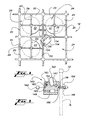
- FIG. 4 is a partial plan view of the top guide of FIG. 2 .
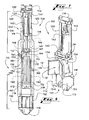
- FIG. 5 is an exploded perspective view of an apparatus for removing the dry tube assembly from engagement with the top guide of FIG. 2 .
- FIG. 6 is a front elevation view of the apparatus of FIG. 5 .
- FIG. 7 is a partial perspective view of the apparatus of FIG. 5 and the top guide of FIG 2 .
- FIG. 8 is a cross-sectional elevation view of a presser foot of the apparatus of FIG. 5 .
- FIGs. 9-12 are side elevation views of a ratcheting cam of the apparatus of FIG. 5 .
- FIG. 13 is a perspective view of an encapsulation sleeve for use with the apparatus of FIG. 5 .
- FIGs. 14 and 15 are plan views of the apparatus of FIG. 5 and the encapsulation sleeve of FIG. 13 .
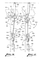
- FIGs. 16-19 are partial side elevation views of the apparatus of FIG. 5 that illustrate a method of removing a dry tube assembly from the top guide of FIG. 2 .
- the present disclosure describes an exemplary apparatus and method for removing a dry tube assembly from deployment in a boiling water reactor (BWR) pressure vessel.
- the apparatus is configured to buckle the dry tube assembly such that the dry tube assembly can be removed without exercising or stressing a joint that connects a plunger assembly to a dry tube.
- the apparatus can be configured to work in other environments or to remove other elements according to the teachings of the present disclosure.
- an exemplary boiling water reactor (BWR) 8 includes a pressure vessel 10 and support structures.
- the illustrated support structures include a top guide 12 and a bottom guide 14.
- support structures are configured to support elements of the BWR 8.
- the top guide 12 and the bottom guide 14 each support a dry tube assembly 16.
- a single dry tube assembly 16 is illustrated although BWRs typically include multiple dry tube assemblies 16 positioned in the pressure vessel 10 as well as fuel bundles, control rods, and other components of a boiling water reactor.
- Fuel bundles 20 and control rods 22 are illustrated in FIG. 4 and described in further detail below.
- the illustrated top guide 12 is a support grid that guides fuel bundles 20 as they are raised and lowered with control rods 22.
- Each control rod 22 supports a group of fuel bundles 20 and raises and lowers the group of fuel bundles 20 through a fuel bundle space 24 in the top guide 12.
- the fuel bundles 20 within a group are guided by the walls of the fuel bundle space 24 and are partitioned and supported by a control rod blade 26 of the corresponding control rod 22.
- a recess 30 is formed at the bottom of the top guide 12 and at an intersection 32 of the support grid of the top guide 12.
- the recess 30 functions as an anchor point and is configured to receive an upper end of the dry tube assembly 16, as described in further detail below.
- the bottom guide 14 includes a support tube 34 in which the lower portion of the dry tube assembly 16 is received.
- the dry tube assembly 16 includes a plunger assembly 40 and a dry tube 42.
- the illustrated plunger assembly 40 is connected to the illustrated dry tube 42 with a welded joint 44 although other types of joints are within the scope of the disclosure.
- the illustrated plunger assembly 40 includes a displaceable spring-biased plunger 50 that facilitates securing the position of the dry tube assembly 16 in the pressure vessel 10.
- the plunger 50 includes an end knob 52 that is configured to be received in the recess 30 to anchor the dry tube assembly 16 in position.
- the plunger 50 slides within a plunger guide 54 and a compression spring 56 is housed in the plunger guide 54 so as to bias the plunger 50 outwardly.
- the plunger 50 includes a boss 58 that facilitates pressing the plunger 50 inwardly.
- the boss 58 can be engaged to facilitate removing the dry tube assembly 16 without pressing the plunger 50 inwardly.
- the boss 58 provides a reference to facilitate positioning an apparatus to engage the dry tube assembly 16.
- dry tubes provide housing for sensors and position the sensors in the core region of the reactor.
- Various dry tube assemblies that have different sections or lengths, different plunger assemblies, and different configurations for housing different sensors or monitoring systems are within the scope of this disclosure.
- the apparatus described herein is not limited to operation with the illustrated dry tube assembly but is operable with various dry tube assemblies. Further, in alternative embodiments, the apparatus can be configured for use with other dry tube assemblies according to the teachings of this disclosure.
- the dry tube assembly 16 is lowered into the open reactor pressure vessel 10 from above, guided through a fuel bundle space 24, and guided through an opening in the bottom guide 14 and into the support tube 34.
- the plunger 50 is pressed inwardly to compress the spring 56 and the dry tube assembly 16 is aligned with the intersection 32 of the top guide 12 where the recess 30 is located.
- the plunger 50 is then released and extends due to force from the spring 56 such that the end knob 52 is received in the recess 30.
- the dry tube assembly 16 is secured in an operating position in the pressure vessel 10.
- an apparatus 100 is configured to remove the dry tube assembly 16 from the operating position in the pressure vessel 10.
- the dry tube assembly 16 is typically removed and replaced as part of routine maintenance or if it becomes damaged or ceases to operate properly.
- the apparatus 100 is configured to remove the dry tube assembly 16 without exercising or stressing the joint 44 and without pressing the plunger 50 inwardly to compress the spring 56.
- the apparatus 100 can remove dry tube assemblies 16 where the joint 44 has become corroded or it is otherwise undesirable to exercise the joint 44.
- the apparatus 100 initiates buckling and buckles the dry tube assembly 16 to remove the upper end of the dry tube assembly 16 from the recess 30 and lifts the dry tube assembly 16 out of the operating position.
- the dynamic components of the illustrated apparatus are operated by pressure driven cylinders. Fluid or air pressure is transferred from fluid pumps (not shown) to each of the cylinders by pressure hoses (not shown).
- the fluid pumps are controlled with a control system (not shown).
- the control system interfaces with an operator and/or a computer that controls the operation of the apparatus.
- the apparatus 100 includes a frame 110 that supports, houses, and positions elements of the apparatus 100.
- the illustrated frame 110 includes two longitudinal arms 112, 113 that are substantially parallel and symmetric to one another.
- the arms 112, 113 are substantially vertical when the apparatus 100 is mounted to the top guide 12.
- Upper and lower blocks 114, 116 connect the upper and lower ends of the arms 112, 113 to one another.
- the arms 112, 113 each include a ledge 118 and a fork 120 that facilitate mounting the apparatus 100 to the top guide 12, as described in further detail below.
- Hoist cables 122 are attached to the upper block 114 and facilitate positioning the apparatus 100 in the pressure vessel 10 and mounting the apparatus 100 to the top guide 12.
- the illustrated apparatus 100 includes a mounting feature that permits the apparatus 100 to be mounted to the illustrated top guide 12 and to top guides of different depths.
- the illustrated mounting feature includes the ledges 118, the forks 120, and a slide 130.
- the illustrated forks 120 are integral to the arms 112, 113 and the slide 130 includes apertures 132 that slidably receive the forks 120 such that the slide 130 is able to travel along the length of the forks 120.
- the illustrated forks 120 permit the slide 130 to move along a length between the upper block 114 and the ledges 118.
- the illustrated slide 130 includes a pair of teeth 134 that are configured to be received in fuel bundle spaces 24 of the top guide 12 that are separated by the intersection 32.
- the teeth-receiving fuel bundle spaces 24 are adjacent to the fuel bundle space 24 where the apparatus 100 is received, as described in further detail below.
- the apparatus 100 further includes a clamping assembly 136 and a positioning assembly 138 that controls the position, movement, and orientation of the clamping assembly 136.
- the illustrated positioning assembly 138 includes an upper positioning assembly 139 that is associated with the upper end of the clamping assembly 136 and a lower positioning assembly 140 that is associated with the lower end of the clamping assembly 136.
- the upper positioning assembly 139 includes a presser foot 141 that is connected to the upper block 114 by a presser foot cylinder 142.
- the presser foot cylinder 142 is hingedly connected to the upper block 114. Extending and retracting the presser foot cylinder 142 moves the presser foot 141.
- the presser foot 141 is directed along a path 144 by ratcheting cams 146 that are housed in the inner walls of the arms 112, 113.
- the presser foot includes protrusions 147 that follow the surface of the cams 146.
- the ratcheting cams 146 are biased to rotate in a direction that is opposite the direction that the presser foot 141 moves along the path 144.
- the rotational bias of the ratcheting cam 146 is represented by compression spring 145 although rotational springs, other biasing mechanisms, and other configurations can be used.
- the structure of the arms 112, 113 limits the rotation of the ratcheting cams 146 in either direction.
- the extension and contraction of the presser foot cylinder 142 and the contact between the protrusions 147 and the path defining surface of the ratcheting cams 146 moves the presser foot 141 along the cam path 144.
- the protrusion 147 contacts and rotates the ratcheting cams 146 (see FIG. 11 ).
- the protrusion 147 clears the ratcheting cam 146 and spring 145 rotates the ratcheting cams 146 to close the portion of the path 144 that the protrusion 147 just traveled along.
- the protrusion 147 is directed along the next segment of the path 144 by the ratcheting cams 146 when the presser foot cylinder 142 retracts or reverses direction.
- FIGs. 10-12 illustrate the movement of the protrusion 147 along the path 144 and the operation of the cam 146 as the presser foot cylinder 142 extends.
- the function of the cam 146 and the protrusion 147 is substantially the same as the presser foot cylinder 142 is retracted from the position illustrated in FIG. 12 .
- the presser foot 141 includes a base 148 and an outer shell 150 that are pivotably connected to one another.
- the base 148 is attached to the lower end of the presser foot cylinder 142.
- a compression spring 152 biases the outer shell 150 forward.
- the presser foot 141 is configured to receive and engage the plunger boss 58.
- the illustrated presser foot 141 includes a pair of fingers 154 that extend outwardly and are configured to receive the dry tube assembly 16 therebetween.
- the spacing between the fingers 154 is greater than the diameter of the illustrated plunger 50 and less than the diameter of the plunger boss 58 such that the presser foot 141 can move along a length of the dry tube assembly 16 with the plunger 50 between the fingers 154 and the fingers 154 can contact and engage the plunger boss 58.
- the fingers 154 are biased slightly downward by the spring 152.
- the spring-biased fingers 154 provide a visual indication of when the boss 58 is in contact with the fingers 154.
- the bottoms of the fingers 154 include a pocket 156 for receiving the plunger boss 58.
- the illustrated pocket 156 is configured to engage the plunger boss 58.
- the pocket includes a lip 158 for capturing the plunger boss 58 as the presser foot 141 moves outwardly and upwardly along a lower portion of the path 144.
- the downward bias of the fingers 154 facilitates capturing the boss 58 as the downward angle of the fingers 154 permits the lip 158 to slide or drop over the boss 58. Alternatively described, the downward bias of the fingers 154 facilitates guiding the boss 58 into the pocket 156.
- the illustrated presser foot 141 includes sensors 160 that are configured to identify when the plunger boss 58 is received in the pocket 156. As the plunger boss 58 is received in the pocket 156, the outer shell 150 is rotated to compress the spring (145) 152. The illustrated sensors 160 identify when the outer shell 150 is rotated with respect to the base 148 as the sensor 160 on the base 148 is in contact with or in proximity to the sensor 160 on the outer shell 150. Other configurations and types of sensors 160 can be used to identify when the plunger boss 58 is received in the pocket 156 or otherwise when the apparatus 100 is positioned to engage the dry tube assembly 16 as described in further detail below.
- a clamping assembly 136 that is configured to engage and encapsulate the dry tube assembly 16 includes clamp jaws 172 (see FIGs. 14 and 15 ) that are supported and positioned by a plate 174.
- the upper end of the plate 174 is hingedly connected to the presser foot 141 to connect the clamping assembly 136 to the upper positioning assembly (138) 139.
- the clamp jaws 172 are controlled by clamp cylinders 176.
- the clamping assembly 136 is configured to apply an encapsulation sleeve 180 to the dry tube assembly 16.
- the illustrated encapsulation sleeve 180 includes a pair of halves 182, 183 that are configured to be secured to one another.
- the illustrated halves 182, 183 each include ridges 184 that are configured to engage one another when the halves 182, 183 are combined.
- the halves 182, 183 can be combined around dry tube assemblies of various diameters.
- the halves 182, 183 are connected with a living hinge 186 that includes strips 188 defined by apertures and notches to facilitate attaching the encapsulation sleeve 180 to and removing the encapsulation sleeve 180 from the clamping assembly 136.
- the encapsulation sleeve 180 is configured to be attached to the clamping assembly 136 such that the clamp jaws 172 can close or wrap the encapsulation sleeve 180 around the dry tube assembly 16 as the clamp jaws 172 engage the dry tube assembly 16.
- the encapsulation sleeve 180 is configured to be wrapped around the dry tube assembly 16 to encapsulate the joint 44 and prevent debris from falling into the pressure vessel 10.
- the clamping assembly 136 includes a hook 189 and the encapsulation sleeve 180 is attached to the clamping assembly 136 as a strip 188 wraps around the hook 189. Further, referring to FIGs.
- the clamping assembly 136 includes a cutting mechanism 185 that cuts the strip 188 as the clamp jaws 172 wrap the encapsulation sleeve 180 around the dry tube assembly 16. Once the strips 188 are cut, the encapsulated dry tube assembly 16 can be released by the clamping assembly 136 as the clamp jaws 172 are opened. Once the strips 188 are cut, the strips 188 do not hold the encapsulation sleeve 180 on the hook 189.
- the lower end of the clamping assembly 136 is coupled to the lower positioning assembly 140.
- the lower end of the clamping assembly 136 includes protrusions 178 that are configured to follow a cam track.
- the lower positioning assembly 140 includes displaceable cam plates 190 and cam plate cylinders 192 that are housed in the lower block 116.
- the cam plates 190 each include a cam track 194 that receives one of the protrusions 178.
- the cam plate cylinders 192 can move the cam plates 190 to move the protrusions 178 along the cam tracks 194.
- the illustrated cam plates 190 are configured to be displaced in a substantially vertical direction and the illustrated cam tracks 194 include substantially vertical segments 195, 196 that are offset from one another and a medial diagonal segment 197 that connects the vertical segments 195, 196.
- the illustrated positioning apparatus provides that movement, positioning, and orientation of the clamping assembly 136 can be achieved by operating either or each of the presser foot cylinder 142 and the cam plate cylinders 192.
- the presser foot cylinder 142 controls the vertical movement of the clamping assembly 136.
- the connection between the clamping assembly 136 and the cam plates 190 permits the clamping assembly 136 to move vertically with the presser foot 141 without synching the movement with the cam plate cylinders 192.
- the rotation of the clamping assembly 136 is a function of the extension of the presser foot cylinder 142 and the extension of the cam plate cylinders 192.
- the rotation of the clamping assembly 136 can be controlled by operating the presser foot cylinder 142.
- the presser foot cylinder 142 can be operated to move the upper end of the clamping assembly 136 along a path that is substantially similar to the cam path 144 while the lower end of the clamping assembly 136 moves along a vertical segment 195, 196 of the cam track 194.
- the rotation of the clamping assembly 136 can be controlled by operating the cam plate cylinders 192.
- the position of the upper end of the clamping assembly 136 can be maintained while the cam plate cylinders 192 are operated to move the lower end of the clamping assembly 136 as the protrusions 178 move along the medial segment 197 of the cam track 194.
- the illustrated apparatus 100 is configured such that operation of the presser foot cylinder 142 moves the clamping assembly 136 into position to engage and encapsulate the dry tube assembly 16, such that subsequent operation of the cam plate cylinders 192 moves the clamping assembly 136 to initiate buckling of the dry tube assembly 16, and such that subsequent operation of the presser foot cylinder 142 continues to buckle the dry tube assembly 16 and removes the dry tube assembly 16 from engagement with the top guide 12.
- An exemplary method of operation of the apparatus 100 is now described in further detail.
- an exemplary method of operating the apparatus 100 is now described although the apparatus 100 can be operated according to other methods.
- the described exemplary method can be modified by adding or omitting steps, rearranging the order of the steps, combinations thereof, and the like.
- the fuel bundles 20 surrounding the dry tube assembly 16 are removed such that the apparatus 100 can be positioned adjacent to the dry tube assembly 16 and such that the apparatus 100 has room to operate without being obstructed by or damaging fuel bundles 20, control rods 22, control rod blades 26, or any other element of the pressure vessel 10.
- the profile of the apparatus 100 minimizes the number of fuel bundles 20 that must be removed during service.
- the apparatus 100 occupies and operates in approximately the space of a single fuel bundle 20.
- the encapsulation sleeve 180 is attached to the clamping assembly 136 as described above. Referring to FIGs. 4 and 7 , the apparatus 100 is then lowered through the appropriate fuel bundle space 24 and mounted to the intersection 32 of the top guide 12.
- the teeth 134 of the slide 130 are fuel bundle spaces 24 that are diagonally positioned with respect to one another.
- the teeth 134 are configured to closely position the apparatus 100 with respect to the intersection 32 and the weight of the apparatus 100 pulls the apparatus 100 against the intersection 32.
- the cables 122 are then tightened to pull the ledges 118 into contact with the bottom of the top guide 12 to secure or mount the apparatus 100 to the top guide 12.
- This mechanism permits the apparatus 100 to accommodate a range of top guide heights without reconfiguring the apparatus 100 since the apparatus 100 registers against the bottom of the top guide 12.
- the illustrated mounting mechanism consistently positions the apparatus 100 with respect to the bottom of the top guide 12.
- the apparatus 100 is mounted to the top guide 12 and positioned with respect to the dry tube assembly 16 so as to be able to operate to remove the dry tube assembly 16.
- the operation of the apparatus 100 is generally accomplished through operation of the cylinders. Through operation of the cylinders, the apparatus 100 functions to engage, encapsulate, buckle, and remove the dry tube assembly 16 from engagement with the top guide 12.
- the presser foot cylinder 142 is actuated and extends to move the presser foot 141 along the cam path 144 toward the dry tube assembly 16 until the plunger 50 is received between the fingers 154.
- the presser foot 141 then continues down along the length of the plunger 50 until the plunger boss 58 is received in the pocket 156.
- the sensors 160 or operator vision can be used to recognize that the plunger boss 58 is received in the pocket 156.
- the sensors 160 provide an output or indicator to a display to alert an operator that the clamping assembly 136 is in position to engage the dry tube assembly 16.
- the sensors 160 can output machine readable instructions that cease the extension of the presser foot cylinder 142. In either case, operation of the presser foot cylinder 142 is momentarily stopped such that the presser foot 141 does not substantially press down on the plunger boss 58 or otherwise exercise the joint 44.
- the clamping assembly 136 moves with the presser foot 141 toward and down the dry tube assembly 16 and positions the encapsulation sleeve 180 and the clamp jaws 172 proximate the dry tube assembly 16.
- the clamping assembly 136 is positioned such that the clamp jaws 172 engage the dry tube assembly 16 above and below the joint 44
- the length of the dry tube assembly 16 between the clamp jaws 172 is a supported length 200 and the length of the dry tube assembly below the lower clamp jaw 172 is an unsupported length 202.
- the supported length 200 is supported to support the joint 44 as the unsupported length 202 is buckled.
- the clamp cylinders 176 are actuated to encapsulate the joint 44 with the encapsulation sleeve 180 and to engage the dry tube assembly 16 with the clamp jaws 172.
- the cam plate cylinders 192 are then actuated to initiate buckling of the dry tube assembly 16.
- the protrusions 178 move through the diagonal segments 197 of the cam tracks 194 and the clamping assembly 136 rotates about the hinged connection to the presser foot 141.
- the clamping assembly 136 rotates, the length of the dry tube assembly 16 that is engaged by the clamp jaws 172 is displaced along with the clamping assembly 136 and the dry tube assembly 16 is buckled or buckling is initiated along the unsupported length 202.
- the dry tube assembly 16 continues to buckle along the unsupported length 202 as the presser foot cylinder 142 is again actuated and extended.
- the presser foot 141 and the clamping assembly 136 both move downward as the presser foot 141 continues along the downward segment of the cam path 144.
- the dry tube assembly 16 continues to buckle along the unsupported length 202 and the end 52 of the dry tube 42 assembly is removed from the recess 30 without exercising the joint 44 or otherwise buckling the dry tube assembly 16 along the supported length 200. Since the presser foot 141 and the clamping assembly 136 move substantially as a unit, a force is not applied to the plunger 50 as the presser foot 141 moves downward.
- the presser foot cylinder 142 can be actuated to retract and move the dry tube assembly 16 away from the intersection 32 and upward as the presser foot 141 moves along the cam path 144.
- the apparatus 100 can then be removed along with the engaged dry tube assembly 16 by lifting the apparatus 100 through the fuel bundle space 24 with the hoist cables 122.
Landscapes
- Engineering & Computer Science (AREA)
- Physics & Mathematics (AREA)
- Plasma & Fusion (AREA)
- General Engineering & Computer Science (AREA)
- High Energy & Nuclear Physics (AREA)
- Mechanical Engineering (AREA)
- Monitoring And Testing Of Nuclear Reactors (AREA)
- Automatic Assembly (AREA)
- Cleaning In General (AREA)
Description
- This disclosure relates generally to apparatuses and methods for servicing nuclear reactor pressure vessels.
- A boiling water reactor (BWR) includes dry tubes that provide a housing within the reactor vessel that positions sensors, such as nuclear flux detectors and protects them from reactor operating pressure, water, and steam. The dry tubes extend from the bottom of the reactor vessel to just below an upper core support grid, and a spring loaded plunger assembly is attached to the upper end of each dry tube to engage the dry tube with an anchor point in the bottom of the upper support grid.
- The dry tube may need to be removed and replaced, for example, as sensors in the dry tube stop working. As the dry tube is deployed or installed in the reactor vessel, a welded joint between the spring loaded plunger assembly and the dry tube can become corroded and the plunger assembly can fail to operate properly. As such, the dry tube becomes stuck and difficult to remove and replace. In such instances, attempting to remove the dry tube by operating the plunger assembly can cause the corroded joint to fail and very undesirably cause debris to fall into the reactor.
-
US 4313793 describes a machine for smoothly and controllably winding or unwinding a stiff in-core-instrument tube onto and off of a reel during refueling of a nuclear reactor. The machine includes a frame and a circular reel having a substantially continuous helical groove adapted to receive the tube extending around the circumference of the reel. A plurality of cam rollers are carried by the frame and closely spaced around the circumference of the reel. The rollers keep the tube in the groove whereby the tube may be more easily wound onto or off of the reel.JP1133179 - detaching an intra-furnace instrumentation tube from an upper grid plate in a furnace without cutting them off. A pair of frames are provided on lower parts of an upper fixed plate, with an air cylinder between the pair of frames and a slide plate for a piston of the air cylinder. A fork is attached to the slide plate for holding an intra-furnace instrumentation tube. A lower fixed plate is provided on a lower part of the slide plate and a fixed member is provided on lower parts of the pair of frames. A vibration generating device is provided between the fixed member and the lower fixed plate. By vibrating the intra-furnace instrumentation tube through the pair of frames, sludge and water scale accumulated in a gap between an inside tube and an outside tube are eliminated and sticking is removed, and the intra-furnace instrumentation tube can be detached from an upper grid plate. Therefore, a heretofore unaddressed need exists in the industry to address the aforementioned deficiencies and inadequacies. What is needed is an apparatus and method for safely and efficiently removing a dry tube.
- The various embodiments of the present disclosure overcome the shortcomings of the prior art by providing a dry tube removal apparatus that is configured to buckle a dry tube assembly to facilitate removal of the dry tube assembly from an operating position in a reactor vessel. The present invention resides in an apparatus and a method for removing a dry tube assembly in a reactor vessel as recited in the appended claims.
- According to a first exemplary embodiment, an apparatus includes a mounting structure configured to mount the assembly to a top guide of a reactor vessel, a clamping assembly configured to engage a dry tube assembly, and a positioning assembly that is configured to position and move the clamping assembly. Once the apparatus is mounted to the top guide, the positioning assembly is operated to move the clamping assembly into position to engage the dry tube assembly, and the clamping assembly is operated to engage the dry tube assembly and support a length of the dry tube assembly that includes a joint that connects the plunger assembly and the dry tube. The positioning assembly is
- then operated to move the clamping assembly so as to initiate buckling along an unsupported length of the dry tube assembly. Once buckling is initiated, the upper end of the dry tube assembly can be removed from engagement with the top guide without operating the plunger assembly or otherwise stressing the joint.
- An exemplary mounting structure is configured to mount to a range of top guide depths. The mounting structure includes a slide that is slidably attached to a frame of the apparatus. The slide is received in the support grid of the top guide and against the top of the top guide. The frame is hoisted to bring the frame into contact with the bottom of the top guide while the slide remains in contact with the top guide such that top guide is clamped between the slide and the frame. As such, the apparatus is secured in an operating position. In alternative embodiments, a mounting structure that clamps to the top guide can be actuated by a cylinder or other motorized mechanism.
- The positioning assembly includes and upper positioning assembly and a lower positioning assembly. An exemplary upper positioning assembly includes a presser foot that is driven along a path by a presser foot cylinder. The path is defined by a ratcheting cam that controls the direction of movement of the presser foot as the presser foot cylinder moves the presser foot. The upper end of the clamping assembly is hingedly connected to the presser foot and is positioned along with the presser foot. The lower positioning assembly includes a structure that includes a cam track, a buckling cylinder that displaces the cam track structure, and a cam track follower that couples the lower end of the clamping assembly to the lower positioning assembly. The cam track follower can be a protrusion that is received in the cam track. The position and orientation of the clamping assembly is a function of the extension of the presser foot cylinder, the position of the presser foot along the path, and the position of the cam track follower along the cam track. The position of the cam track follower along the cam track is a function of the extension of the buckling cylinder and the position of the presser foot.
- According to an exemplary method, to move the clamping assembly into position to engage the dry tube assembly, the presser foot moves along the path until the presser foot contacts a plunger boss or other structure of the dry tube assembly. In various embodiments, the presser foot is configured to receive and engage the plunger boss. For example, the presser foot can include spring-biased fingers that define a pocket for receiving the plunger boss and the pocket can include a lip that engages the plunger boss.
- The clamping assembly is then operated to engage the dry tube assembly. According to an exemplary embodiment, the clamping assembly is configured to engage the dry tube above and below the joint connecting the plunger assembly to the dry tube. In this manner, the joint is supported while the dry tube assembly is bent and buckled. In general, the dry tube assembly is bent along a length of the dry tube assembly that is defined between an end of the dry tube assembly and a point where the apparatus engages the dry tube assembly that is closest to the end. In various embodiments, the clamping assembly applies an encapsulation tube to the dry tube assembly to encapsulate and further support the joint.
- The positioning assembly rotates the clamping assembly to initiate buckling of the dry tube assembly as it is engaged by the clamping assembly. The clamping assembly rotates about an axis that is substantially orthogonal to the longitudinal axis of the dry tube assembly. The buckling cylinders are actuated to move the cam follower along the cam track, which rotates the clamping assembly about the hinged connection to the presser foot. Once the dry tube assembly is bent, the presser foot cylinder is actuated to move the presser foot and the clamping assembly downward to compress and continue to buckle the dry tube assembly and to remove the upper end of the dry tube assembly from engagement with the bottom of the top guide.
- The foregoing has broadly outlined some of the aspects and features of the present disclosure, which should be construed to be merely illustrative of various potential applications. Other beneficial results can be obtained by applying the disclosed information in a different manner or by combining various aspects of the disclosed embodiments. Accordingly, other aspects and a more comprehensive understanding may be obtained by referring to the detailed description of the exemplary embodiments taken in conjunction with the accompanying drawings, in addition to the scope defined by the claims.
- There follows a detailed description of embodiments of the invention by way of example only with reference to the accompanying drawings, in which:
-
FIG. 1 is a cut-away view of a boiling water reactor pressure vessel and a dry tube assembly, according to a first exemplary embodiment of the present disclosure. -
FIG. 2 is a partial perspective view of the dry tube assembly and a top guide of the pressure vessel ofFIG. 1 . -
FIG. 3 is a partial cross-sectional elevation view of the dry tube assembly and a top guide of the pressure vessel ofFIG. 1 . -
FIG. 4 is a partial plan view of the top guide ofFIG. 2 . -
FIG. 5 is an exploded perspective view of an apparatus for removing the dry tube assembly from engagement with the top guide ofFIG. 2 . -
FIG. 6 is a front elevation view of the apparatus ofFIG. 5 . -
FIG. 7 is a partial perspective view of the apparatus ofFIG. 5 and the top guide ofFIG 2 . -
FIG. 8 is a cross-sectional elevation view of a presser foot of the apparatus ofFIG. 5 . -
FIGs. 9-12 are side elevation views of a ratcheting cam of the apparatus ofFIG. 5 . -
FIG. 13 is a perspective view of an encapsulation sleeve for use with the apparatus ofFIG. 5 . -
FIGs. 14 and 15 are plan views of the apparatus ofFIG. 5 and the encapsulation sleeve ofFIG. 13 . -
FIGs. 16-19 are partial side elevation views of the apparatus ofFIG. 5 that illustrate a method of removing a dry tube assembly from the top guide ofFIG. 2 . - As required, detailed embodiments are disclosed herein. It must be understood that the disclosed embodiments are merely exemplary of the disclosure that may be embodied in various and alternative forms, and combinations thereof. As used herein, the word "exemplary" is used expansively to refer to embodiments that serve as illustrations, specimens, models, or patterns. The figures are not necessarily to scale and some features may be exaggerated or minimized to show details of particular components. In other instances, well-known components, systems, materials, or methods have not been described in detail in order to avoid obscuring the present disclosure. Therefore, specific structural and functional details disclosed herein are not to be interpreted as limiting, but merely as a basis for the claims and as a representative basis for teaching one skilled in the art.
- For purposes of teaching, the present disclosure describes an exemplary apparatus and method for removing a dry tube assembly from deployment in a boiling water reactor (BWR) pressure vessel. The apparatus is configured to buckle the dry tube assembly such that the dry tube assembly can be removed without exercising or stressing a joint that connects a plunger assembly to a dry tube. In alternative embodiments, the apparatus can be configured to work in other environments or to remove other elements according to the teachings of the present disclosure.
- Referring to
FIG. 1 , an exemplary boiling water reactor (BWR) 8 includes apressure vessel 10 and support structures. The illustrated support structures include atop guide 12 and abottom guide 14. Generally described, support structures are configured to support elements of theBWR 8. Thetop guide 12 and thebottom guide 14 each support adry tube assembly 16. For purposes of clarity, a singledry tube assembly 16 is illustrated although BWRs typically include multipledry tube assemblies 16 positioned in thepressure vessel 10 as well as fuel bundles, control rods, and other components of a boiling water reactor. Fuel bundles 20 andcontrol rods 22 are illustrated inFIG. 4 and described in further detail below. - Referring to
FIGs. 1-4 , the illustratedtop guide 12 is a support grid that guides fuel bundles 20 as they are raised and lowered withcontrol rods 22. Eachcontrol rod 22 supports a group of fuel bundles 20 and raises and lowers the group of fuel bundles 20 through afuel bundle space 24 in thetop guide 12. The fuel bundles 20 within a group are guided by the walls of thefuel bundle space 24 and are partitioned and supported by acontrol rod blade 26 of thecorresponding control rod 22. - A
recess 30 is formed at the bottom of thetop guide 12 and at anintersection 32 of the support grid of thetop guide 12. Therecess 30 functions as an anchor point and is configured to receive an upper end of thedry tube assembly 16, as described in further detail below. Thebottom guide 14 includes asupport tube 34 in which the lower portion of thedry tube assembly 16 is received. - As best shown in
FIG. 3 , thedry tube assembly 16 includes aplunger assembly 40 and adry tube 42. The illustratedplunger assembly 40 is connected to the illustrateddry tube 42 with a welded joint 44 although other types of joints are within the scope of the disclosure. The illustratedplunger assembly 40 includes a displaceable spring-biasedplunger 50 that facilitates securing the position of thedry tube assembly 16 in thepressure vessel 10. Theplunger 50 includes anend knob 52 that is configured to be received in therecess 30 to anchor thedry tube assembly 16 in position. Theplunger 50 slides within aplunger guide 54 and acompression spring 56 is housed in theplunger guide 54 so as to bias theplunger 50 outwardly. In addition, theplunger 50 includes aboss 58 that facilitates pressing theplunger 50 inwardly. According to the method described in further detail below, theboss 58 can be engaged to facilitate removing thedry tube assembly 16 without pressing theplunger 50 inwardly. Also, theboss 58 provides a reference to facilitate positioning an apparatus to engage thedry tube assembly 16. - In general, dry tubes provide housing for sensors and position the sensors in the core region of the reactor. Various dry tube assemblies that have different sections or lengths, different plunger assemblies, and different configurations for housing different sensors or monitoring systems are within the scope of this disclosure. The apparatus described herein is not limited to operation with the illustrated dry tube assembly but is operable with various dry tube assemblies. Further, in alternative embodiments, the apparatus can be configured for use with other dry tube assemblies according to the teachings of this disclosure.
- Referring to
FIGs. 1-4 , an exemplary and non-limiting method for installing the dry tube assembly is described to provide context. Thedry tube assembly 16 is lowered into the openreactor pressure vessel 10 from above, guided through afuel bundle space 24, and guided through an opening in thebottom guide 14 and into thesupport tube 34. To secure thedry tube assembly 16 in place, theplunger 50 is pressed inwardly to compress thespring 56 and thedry tube assembly 16 is aligned with theintersection 32 of thetop guide 12 where therecess 30 is located. Theplunger 50 is then released and extends due to force from thespring 56 such that theend knob 52 is received in therecess 30. As theplunger 50 is forced into therecess 30, thedry tube assembly 16 is secured in an operating position in thepressure vessel 10. - Referring to
FIGs. 5 and6 , anapparatus 100 is configured to remove thedry tube assembly 16 from the operating position in thepressure vessel 10. Thedry tube assembly 16 is typically removed and replaced as part of routine maintenance or if it becomes damaged or ceases to operate properly. Theapparatus 100 is configured to remove thedry tube assembly 16 without exercising or stressing the joint 44 and without pressing theplunger 50 inwardly to compress thespring 56. As such, theapparatus 100 can removedry tube assemblies 16 where the joint 44 has become corroded or it is otherwise undesirable to exercise the joint 44. Generally described, theapparatus 100 initiates buckling and buckles thedry tube assembly 16 to remove the upper end of thedry tube assembly 16 from therecess 30 and lifts thedry tube assembly 16 out of the operating position. - Generally described, the dynamic components of the illustrated apparatus are operated by pressure driven cylinders. Fluid or air pressure is transferred from fluid pumps (not shown) to each of the cylinders by pressure hoses (not shown). The fluid pumps are controlled with a control system (not shown). In various embodiments, the control system interfaces with an operator and/or a computer that controls the operation of the apparatus.
- Referring to
FIG. 5 , theapparatus 100 includes aframe 110 that supports, houses, and positions elements of theapparatus 100. The illustratedframe 110 includes twolongitudinal arms arms apparatus 100 is mounted to thetop guide 12. Upper andlower blocks arms arms ledge 118 and afork 120 that facilitate mounting theapparatus 100 to thetop guide 12, as described in further detail below. Hoistcables 122 are attached to theupper block 114 and facilitate positioning theapparatus 100 in thepressure vessel 10 and mounting theapparatus 100 to thetop guide 12. - Referring to
FIGs. 4-7 , theillustrated apparatus 100 includes a mounting feature that permits theapparatus 100 to be mounted to the illustratedtop guide 12 and to top guides of different depths. The illustrated mounting feature includes theledges 118, theforks 120, and aslide 130. The illustratedforks 120 are integral to thearms slide 130 includesapertures 132 that slidably receive theforks 120 such that theslide 130 is able to travel along the length of theforks 120. The illustratedforks 120 permit theslide 130 to move along a length between theupper block 114 and theledges 118. - The illustrated
slide 130 includes a pair ofteeth 134 that are configured to be received infuel bundle spaces 24 of thetop guide 12 that are separated by theintersection 32. The teeth-receivingfuel bundle spaces 24 are adjacent to thefuel bundle space 24 where theapparatus 100 is received, as described in further detail below. - The
apparatus 100 further includes a clampingassembly 136 and apositioning assembly 138 that controls the position, movement, and orientation of the clampingassembly 136. The illustratedpositioning assembly 138 includes anupper positioning assembly 139 that is associated with the upper end of the clampingassembly 136 and alower positioning assembly 140 that is associated with the lower end of the clampingassembly 136. - Referring to
FIGs. 5 ,6 , and8 , theupper positioning assembly 139 includes apresser foot 141 that is connected to theupper block 114 by apresser foot cylinder 142. Thepresser foot cylinder 142 is hingedly connected to theupper block 114. Extending and retracting thepresser foot cylinder 142 moves thepresser foot 141. Referring toFIGs. 5 ,6 , and9 , thepresser foot 141 is directed along apath 144 by ratchetingcams 146 that are housed in the inner walls of thearms protrusions 147 that follow the surface of thecams 146. The ratchetingcams 146 are biased to rotate in a direction that is opposite the direction that thepresser foot 141 moves along thepath 144. The rotational bias of theratcheting cam 146 is represented bycompression spring 145 although rotational springs, other biasing mechanisms, and other configurations can be used. The structure of thearms cams 146 in either direction. - Referring to
FIGs. 9-12 , the extension and contraction of thepresser foot cylinder 142 and the contact between theprotrusions 147 and the path defining surface of the ratchetingcams 146 moves thepresser foot 141 along thecam path 144. As thepresser foot 141 moves along segments of thepath 144, theprotrusion 147 contacts and rotates the ratcheting cams 146 (seeFIG. 11 ). As theprotrusion 147 continues along thepath 144, theprotrusion 147 clears theratcheting cam 146 andspring 145 rotates the ratchetingcams 146 to close the portion of thepath 144 that theprotrusion 147 just traveled along. Theprotrusion 147 is directed along the next segment of thepath 144 by the ratchetingcams 146 when thepresser foot cylinder 142 retracts or reverses direction.FIGs. 10-12 illustrate the movement of theprotrusion 147 along thepath 144 and the operation of thecam 146 as thepresser foot cylinder 142 extends. The function of thecam 146 and theprotrusion 147 is substantially the same as thepresser foot cylinder 142 is retracted from the position illustrated inFIG. 12 . - Referring to
FIGs. 5 and8 , thepresser foot 141 includes abase 148 and anouter shell 150 that are pivotably connected to one another. Thebase 148 is attached to the lower end of thepresser foot cylinder 142. Acompression spring 152 biases theouter shell 150 forward. - Referring to
FIG. 8 , thepresser foot 141 is configured to receive and engage theplunger boss 58. The illustratedpresser foot 141 includes a pair offingers 154 that extend outwardly and are configured to receive thedry tube assembly 16 therebetween. The spacing between thefingers 154 is greater than the diameter of the illustratedplunger 50 and less than the diameter of theplunger boss 58 such that thepresser foot 141 can move along a length of thedry tube assembly 16 with theplunger 50 between thefingers 154 and thefingers 154 can contact and engage theplunger boss 58. Thefingers 154 are biased slightly downward by thespring 152. The spring-biasedfingers 154 provide a visual indication of when theboss 58 is in contact with thefingers 154. - The bottoms of the
fingers 154 include apocket 156 for receiving theplunger boss 58. The illustratedpocket 156 is configured to engage theplunger boss 58. The pocket includes alip 158 for capturing theplunger boss 58 as thepresser foot 141 moves outwardly and upwardly along a lower portion of thepath 144. The downward bias of thefingers 154 facilitates capturing theboss 58 as the downward angle of thefingers 154 permits thelip 158 to slide or drop over theboss 58. Alternatively described, the downward bias of thefingers 154 facilitates guiding theboss 58 into thepocket 156. - The illustrated
presser foot 141 includessensors 160 that are configured to identify when theplunger boss 58 is received in thepocket 156. As theplunger boss 58 is received in thepocket 156, theouter shell 150 is rotated to compress the spring (145) 152. The illustratedsensors 160 identify when theouter shell 150 is rotated with respect to the base 148 as thesensor 160 on thebase 148 is in contact with or in proximity to thesensor 160 on theouter shell 150. Other configurations and types ofsensors 160 can be used to identify when theplunger boss 58 is received in thepocket 156 or otherwise when theapparatus 100 is positioned to engage thedry tube assembly 16 as described in further detail below. - Referring again to
FIGs. 5 and6 , a clampingassembly 136 that is configured to engage and encapsulate thedry tube assembly 16 includes clamp jaws 172 (seeFIGs. 14 and 15 ) that are supported and positioned by aplate 174. The upper end of theplate 174 is hingedly connected to thepresser foot 141 to connect the clampingassembly 136 to the upper positioning assembly (138) 139. Theclamp jaws 172 are controlled byclamp cylinders 176. - Referring to
FIGs. 13-15 , the clampingassembly 136 is configured to apply anencapsulation sleeve 180 to thedry tube assembly 16. The illustratedencapsulation sleeve 180 includes a pair ofhalves ridges 184 that are configured to engage one another when thehalves halves halves living hinge 186 that includesstrips 188 defined by apertures and notches to facilitate attaching theencapsulation sleeve 180 to and removing theencapsulation sleeve 180 from the clampingassembly 136. - The
encapsulation sleeve 180 is configured to be attached to the clampingassembly 136 such that theclamp jaws 172 can close or wrap theencapsulation sleeve 180 around thedry tube assembly 16 as theclamp jaws 172 engage thedry tube assembly 16. Theencapsulation sleeve 180 is configured to be wrapped around thedry tube assembly 16 to encapsulate the joint 44 and prevent debris from falling into thepressure vessel 10. Referring toFIG. 14 , the clampingassembly 136 includes ahook 189 and theencapsulation sleeve 180 is attached to the clampingassembly 136 as astrip 188 wraps around thehook 189. Further, referring toFIGs. 14 and 15 , the clampingassembly 136 includes acutting mechanism 185 that cuts thestrip 188 as theclamp jaws 172 wrap theencapsulation sleeve 180 around thedry tube assembly 16. Once thestrips 188 are cut, the encapsulateddry tube assembly 16 can be released by the clampingassembly 136 as theclamp jaws 172 are opened. Once thestrips 188 are cut, thestrips 188 do not hold theencapsulation sleeve 180 on thehook 189. - Referring again to
FIGs. 5 and6 , the lower end of the clampingassembly 136 is coupled to thelower positioning assembly 140. The lower end of the clampingassembly 136 includesprotrusions 178 that are configured to follow a cam track. Thelower positioning assembly 140 includesdisplaceable cam plates 190 andcam plate cylinders 192 that are housed in thelower block 116. Thecam plates 190 each include acam track 194 that receives one of theprotrusions 178. Thecam plate cylinders 192 can move thecam plates 190 to move theprotrusions 178 along the cam tracks 194. The illustratedcam plates 190 are configured to be displaced in a substantially vertical direction and the illustrated cam tracks 194 include substantiallyvertical segments diagonal segment 197 that connects thevertical segments - The illustrated positioning apparatus provides that movement, positioning, and orientation of the clamping
assembly 136 can be achieved by operating either or each of thepresser foot cylinder 142 and thecam plate cylinders 192. In general, thepresser foot cylinder 142 controls the vertical movement of the clampingassembly 136. The connection between the clampingassembly 136 and thecam plates 190 permits the clampingassembly 136 to move vertically with thepresser foot 141 without synching the movement with thecam plate cylinders 192. The rotation of the clampingassembly 136 is a function of the extension of thepresser foot cylinder 142 and the extension of thecam plate cylinders 192. - The rotation of the clamping
assembly 136 can be controlled by operating thepresser foot cylinder 142. For example, thepresser foot cylinder 142 can be operated to move the upper end of the clampingassembly 136 along a path that is substantially similar to thecam path 144 while the lower end of the clampingassembly 136 moves along avertical segment cam track 194. Alternatively, the rotation of the clampingassembly 136 can be controlled by operating thecam plate cylinders 192. For example, the position of the upper end of the clampingassembly 136 can be maintained while thecam plate cylinders 192 are operated to move the lower end of the clampingassembly 136 as theprotrusions 178 move along themedial segment 197 of thecam track 194. - The
illustrated apparatus 100 is configured such that operation of thepresser foot cylinder 142 moves the clampingassembly 136 into position to engage and encapsulate thedry tube assembly 16, such that subsequent operation of thecam plate cylinders 192 moves the clampingassembly 136 to initiate buckling of thedry tube assembly 16, and such that subsequent operation of thepresser foot cylinder 142 continues to buckle thedry tube assembly 16 and removes thedry tube assembly 16 from engagement with thetop guide 12. An exemplary method of operation of theapparatus 100 is now described in further detail. - An exemplary method of operating the
apparatus 100 is now described although theapparatus 100 can be operated according to other methods. For example, the described exemplary method can be modified by adding or omitting steps, rearranging the order of the steps, combinations thereof, and the like. - Referring to
FIG. 4 , the fuel bundles 20 surrounding thedry tube assembly 16 are removed such that theapparatus 100 can be positioned adjacent to thedry tube assembly 16 and such that theapparatus 100 has room to operate without being obstructed by or damaging fuel bundles 20,control rods 22,control rod blades 26, or any other element of thepressure vessel 10. The profile of theapparatus 100 minimizes the number of fuel bundles 20 that must be removed during service. Theapparatus 100 occupies and operates in approximately the space of asingle fuel bundle 20. - Before mounting the
apparatus 100 to thetop guide 12, theencapsulation sleeve 180 is attached to the clampingassembly 136 as described above.
Referring toFIGs. 4 and7 , theapparatus 100 is then lowered through the appropriatefuel bundle space 24 and mounted to theintersection 32 of thetop guide 12. Theteeth 134 of theslide 130 arefuel bundle spaces 24 that are diagonally positioned with respect to one another. Theteeth 134 are configured to closely position theapparatus 100 with respect to theintersection 32 and the weight of theapparatus 100 pulls theapparatus 100 against theintersection 32. Thecables 122 are then tightened to pull theledges 118 into contact with the bottom of thetop guide 12 to secure or mount theapparatus 100 to thetop guide 12. This mechanism permits theapparatus 100 to accommodate a range of top guide heights without reconfiguring theapparatus 100 since theapparatus 100 registers against the bottom of thetop guide 12. The illustrated mounting mechanism consistently positions theapparatus 100 with respect to the bottom of thetop guide 12. - Referring to
FIGs. 16-19 , as theledge 118 is positioned against the bottom of thetop guide 12, theapparatus 100 is mounted to thetop guide 12 and positioned with respect to thedry tube assembly 16 so as to be able to operate to remove thedry tube assembly 16. The operation of theapparatus 100 is generally accomplished through operation of the cylinders. Through operation of the cylinders, theapparatus 100 functions to engage, encapsulate, buckle, and remove thedry tube assembly 16 from engagement with thetop guide 12. - Referring to
FIGs. 16 and 17 , thepresser foot cylinder 142 is actuated and extends to move thepresser foot 141 along thecam path 144 toward thedry tube assembly 16 until theplunger 50 is received between thefingers 154. Thepresser foot 141 then continues down along the length of theplunger 50 until theplunger boss 58 is received in thepocket 156. Thesensors 160 or operator vision can be used to recognize that theplunger boss 58 is received in thepocket 156. In various embodiments, thesensors 160 provide an output or indicator to a display to alert an operator that the clampingassembly 136 is in position to engage thedry tube assembly 16. Alternatively, thesensors 160 can output machine readable instructions that cease the extension of thepresser foot cylinder 142. In either case, operation of thepresser foot cylinder 142 is momentarily stopped such that thepresser foot 141 does not substantially press down on theplunger boss 58 or otherwise exercise the joint 44. - The clamping
assembly 136 moves with thepresser foot 141 toward and down thedry tube assembly 16 and positions theencapsulation sleeve 180 and theclamp jaws 172 proximate thedry tube assembly 16. The clampingassembly 136 is positioned such that theclamp jaws 172 engage thedry tube assembly 16 above and below the joint 44 The length of thedry tube assembly 16 between theclamp jaws 172 is a supportedlength 200 and the length of the dry tube assembly below thelower clamp jaw 172 is anunsupported length 202. The supportedlength 200 is supported to support the joint 44 as theunsupported length 202 is buckled. - Referring to
FIGs. 14, 15 , and17 , theclamp cylinders 176 are actuated to encapsulate the joint 44 with theencapsulation sleeve 180 and to engage thedry tube assembly 16 with theclamp jaws 172. - Referring to
FIG. 18 , thecam plate cylinders 192 are then actuated to initiate buckling of thedry tube assembly 16. As thecam plate cylinders 192 are actuated and extend, theprotrusions 178 move through thediagonal segments 197 of the cam tracks 194 and the clampingassembly 136 rotates about the hinged connection to thepresser foot 141. As the clampingassembly 136 rotates, the length of thedry tube assembly 16 that is engaged by theclamp jaws 172 is displaced along with the clampingassembly 136 and thedry tube assembly 16 is buckled or buckling is initiated along theunsupported length 202. - Referring to
FIGs. 11, 12 , and19 , once buckling has been initiated, thedry tube assembly 16 continues to buckle along theunsupported length 202 as thepresser foot cylinder 142 is again actuated and extended. Thepresser foot 141 and the clampingassembly 136 both move downward as thepresser foot 141 continues along the downward segment of thecam path 144. Thedry tube assembly 16 continues to buckle along theunsupported length 202 and theend 52 of thedry tube 42 assembly is removed from therecess 30 without exercising the joint 44 or otherwise buckling thedry tube assembly 16 along the supportedlength 200. Since thepresser foot 141 and the clampingassembly 136 move substantially as a unit, a force is not applied to theplunger 50 as thepresser foot 141 moves downward. - Referring to
FIGs. 12 and19 , once thepresser foot 141 reaches the lowermost point of thecam path 144 or otherwise clears the guidance provided by the ratchetingcam 146 as thepresser foot cylinder 142 extends, thepresser foot cylinder 142 can be actuated to retract and move thedry tube assembly 16 away from theintersection 32 and upward as thepresser foot 141 moves along thecam path 144. Theapparatus 100 can then be removed along with the engageddry tube assembly 16 by lifting theapparatus 100 through thefuel bundle space 24 with the hoistcables 122. - The embodiments have been illustrated in a manner that is intended in all respects to be illustrative rather than restrictive. Those skilled in the art will recognize that many modifications and variations are possible without departing from the scope of the teachings. For example, as used herein, directional references such as top, base, bottom, end , side, inner, outer, upper, middle, lower, front, and rear do not limit the respective elements to such orientation, but merely serve to distinguish these elements from one another.
- The above-described embodiments are merely exemplary illustrations of implementations set forth for a clear understanding of the principles of the disclosure. Variations, modifications, and combinations may be made to the above-described embodiments without departing from the scope of the claims. All such variations, modifications, and combinations are included herein by the scope of the following claims.
- This written description uses examples to disclose the invention, including the best mode, and also to enable any person skilled in the art to practice the invention, including making and using any devices or systems and performing any incorporated methods. The scope of the invention is defined by the claims, and may include other examples that occur to those skilled in the art.
Claims (12)
- An apparatus (100) for removing a dry tube assembly (16) in a reactor vessel, comprising:a clamping assembly (136) configured to engage a dry tube assembly (16); anda positioning assembly (138) that is configured to position the clamping assembly relative to the dry tube assembly and to rotate the clamping assembly (136) about an axis that is substantially orthogonal to a longitudinal axis of the dry tube assembly to initiate buckling of the dry tube assembly (16) that is engaged by the clamping assembly (136), the positioning assembly (138) comprising an upper positioning assembly (139) associated with an upper end of the clamping assembly (136) and a lower positioning assembly (140) associated with a lower end of the clamping assembly (136).
- The apparatus (100) of claim 1, further comprising a mounting structure (110. 130) configured to mount the apparatus (100) to a top guide (12), the mounting structure (110, 130) being configured to position the apparatus with respect to the bottom of the top guide (12).
- The apparatus of claim 2, the mounting structure comprising a frame (110) and a slide (130), the slide (130) being configured to travel along a length of the frame (110).
- The apparatus of any of claims 1 to 3, wherein the upper positioning assembly (139) comprises a presser foot (141) that is configured to position the clamping assembly (136) relative to a dry tube assembly (16), the clamping assembly (136) being hingedly connected to the presser foot (141).
- The apparatus of claim 4, wherein the upper positioning assembly further comprises a ratcheting cam (146) that is configured to guide the presser foot (141) along a predefined path (144).
- The apparatus of any preceding claim, wherein the lower positioning assembly (138) comprises a cam track (194) and a cam track follower (178) that couples the clamping assembly (136) to the cam track (194), the cam track (194) being configured such that the clamping assembly (136) is rotated about the hinged connection as a function of the position of the cam track follower (192) along the cam track (194).
- The apparatus of any of claims 4 to 6, wherein the presser foot (141) comprises a pocket (156) and a lip (158) that are configured to capture a boss (58) of a dry tube assembly.
- The apparatus (100) of any preceding claim, the clamping assembly (136) being configured to apply an encapsulation sleeve (180) to a dry tube assembly (16) and to release the encapsulation sleeve (180) as it is applied.
- A method for removing a dry tube assembly (16), comprising:positioning a clamping assembly (136) relative to a dry tube assembly (16) by means of an upper positioning assembly (139) associated with an upper end of the clamping assembly (136);engaging the dry tube assembly (16) with a clamping assembly (136);rotating the clamping assembly (136) about an axis that is substantially orthogonal to a longitudinal axis of the dry tube assembly (16) by means of the upper positioning assembly and a lower positioning assembly (140) associated with a lower end of the clamping assembly (136), to initiate buckling of the dry tube assembly (16); andmoving the clamping assembly (136) downward to continue to buckle the dry tube assembly (16) and to remove an upper end (52) of the dry tube assembly (16) from a top guide (12).
- The method of claim 9, further comprising mounting an apparatus comprising the clamping assembly (136) to the top guide (12) such that the apparatus (100) is positioned against the bottom of the top guide (12).
- The method of claim 12, further comprising contacting a boss (58) of the dry tube assembly (16) with the upper positioning assembly (139) to position the clamping assembly (136) relative to the dry tube assembly (16).
- The method of claim 11, the clamping assembly (136) being hingedly connected to the upper positioning assembly (138), wherein the rotating step comprises rotating the clamping assembly (136) about the hinged connection.
Applications Claiming Priority (1)
| Application Number | Priority Date | Filing Date | Title |
|---|---|---|---|
| US12/423,661 US8631563B2 (en) | 2009-04-14 | 2009-04-14 | Apparatus and method for removing a dry tube assembly from a nuclear reactor pressure vessel |
Publications (3)
| Publication Number | Publication Date |
|---|---|
| EP2242059A2 EP2242059A2 (en) | 2010-10-20 |
| EP2242059A3 EP2242059A3 (en) | 2012-05-23 |
| EP2242059B1 true EP2242059B1 (en) | 2013-07-24 |
Family
ID=42335105
Family Applications (1)
| Application Number | Title | Priority Date | Filing Date |
|---|---|---|---|
| EP10159633.6A Active EP2242059B1 (en) | 2009-04-14 | 2010-04-12 | Apparatus and method for removing a dry tube assembly from a nuclear reactor pressure vessel |
Country Status (5)
| Country | Link |
|---|---|
| US (1) | US8631563B2 (en) |
| EP (1) | EP2242059B1 (en) |
| JP (1) | JP5634734B2 (en) |
| ES (1) | ES2428844T3 (en) |
| MX (1) | MX345179B (en) |
Families Citing this family (3)
| Publication number | Priority date | Publication date | Assignee | Title |
|---|---|---|---|---|
| JP2789690B2 (en) | 1989-07-17 | 1998-08-20 | 日立化成工業株式会社 | Carbon brush material |
| CN103921099B (en) * | 2014-04-10 | 2016-02-17 | 中国船舶重工集团公司第七○二研究所 | Clamp loading and unloading device for large diameter deep sea simulator |
| US20180161944A1 (en) * | 2016-12-09 | 2018-06-14 | Ge-Hitachi Nuclear Energy Americas Llc | Systems and methods for nuclear reactor dry tube assembly removal and installation |
Family Cites Families (24)
| Publication number | Priority date | Publication date | Assignee | Title |
|---|---|---|---|---|
| US1804843A (en) * | 1929-12-14 | 1931-05-12 | Grant John | Liner puller |
| US2690613A (en) * | 1951-04-24 | 1954-10-05 | Clifford F Bishop | Condenser tube extractor |
| US3986245A (en) * | 1975-04-30 | 1976-10-19 | Combustion Engineering, Inc. | Tube removal method |
| US4077103A (en) * | 1976-09-27 | 1978-03-07 | Kelley Eugene M | Pulling tool |
| US4283826A (en) * | 1978-05-18 | 1981-08-18 | Carrier Corporation | Tube extracting mechanism |
| DE2832122A1 (en) | 1978-07-21 | 1980-01-31 | Kraftwerk Union Ag | MEASURING LAMP FOR BOILING WATER CORE REACTORS |
| US4313793A (en) | 1979-10-22 | 1982-02-02 | Combustion Engineering, Inc. | Machine for removing in-core instrument assemblies from a nuclear reactor |
| US4639998A (en) * | 1984-11-09 | 1987-02-03 | Westinghouse Electric Corp. | Locking tube removal and replacement tool and method in a reconstitutable fuel assembly |
| EP0213392B1 (en) | 1985-08-09 | 1990-02-28 | Siemens Aktiengesellschaft | Apparatus for mounting dry neutron thimble detectors and for cleaning their guide tubes in boiling water reactors |
| US4818471A (en) | 1987-08-10 | 1989-04-04 | Westinghouse Electric Corp. | BWR fuel assembly channel with localized neutron absorber strips for LPRM calibration |
| US4832522A (en) | 1988-01-28 | 1989-05-23 | Adaptive Concepts, Ltd. | Adapter extension for plungers and the like |
| US5037603A (en) * | 1990-08-03 | 1991-08-06 | Westinghouse Electric Corp. | Hand held tool for removing and replacing a top nozzle locking tube |
| US5186437A (en) * | 1991-02-22 | 1993-02-16 | Scott Ted P | Post puller including concrete base pulling means |
| JP2966976B2 (en) | 1991-07-19 | 1999-10-25 | 株式会社東芝 | Neutron instrumentation tube handling equipment |
| US5677413A (en) | 1995-06-15 | 1997-10-14 | Arco Chemical Technology, L.P. | Polyurethane elastomers exhibiting improved demold green strength and water absorption and haze-free polyols suitable for their preparation |
| FR2750491B1 (en) | 1996-06-26 | 1998-09-04 | Framatome Sa | METHOD AND DEVICE FOR GEOMETRICAL CHECKING OF A GUIDED TUBE |
| US5802127A (en) | 1996-09-11 | 1998-09-01 | General Electric Company | Device for protecting in-core monitors against damage during servicing of nuclear reactor |
| JPH11133179A (en) | 1997-10-30 | 1999-05-21 | Toshiba Eng Co Ltd | Furnace instrument tube removal device |
| US6095498A (en) * | 1998-08-07 | 2000-08-01 | Lemoine; James R. | Device for pulling objects |
| JP2000065981A (en) | 1998-08-18 | 2000-03-03 | Toshiba Corp | Furnace instrument tube loading / unloading device |
| US6599067B2 (en) * | 2001-03-26 | 2003-07-29 | Atomic Energy Of Canada Limited | Apparatus for removing pressure tubes |
| US6978983B1 (en) * | 2002-04-25 | 2005-12-27 | Sclease Joseph L | Rod puller apparatus and method |
| JP4178081B2 (en) | 2003-06-23 | 2008-11-12 | 日立Geニュークリア・エナジー株式会社 | Removal device for reactor neutron flux monitor |
| JP2005305599A (en) * | 2004-04-22 | 2005-11-04 | Dai Ichi High Frequency Co Ltd | How to remove a branch pipe |
-
2009
- 2009-04-14 US US12/423,661 patent/US8631563B2/en not_active Expired - Fee Related
-
2010
- 2010-03-31 MX MX2010003608A patent/MX345179B/en active IP Right Grant
- 2010-04-12 ES ES10159633T patent/ES2428844T3/en active Active
- 2010-04-12 EP EP10159633.6A patent/EP2242059B1/en active Active
- 2010-04-13 JP JP2010091882A patent/JP5634734B2/en active Active
Also Published As
| Publication number | Publication date |
|---|---|
| JP2010249816A (en) | 2010-11-04 |
| EP2242059A2 (en) | 2010-10-20 |
| ES2428844T3 (en) | 2013-11-11 |
| JP5634734B2 (en) | 2014-12-03 |
| MX2010003608A (en) | 2010-10-18 |
| US20100257716A1 (en) | 2010-10-14 |
| EP2242059A3 (en) | 2012-05-23 |
| US8631563B2 (en) | 2014-01-21 |
| MX345179B (en) | 2017-01-18 |
Similar Documents
| Publication | Publication Date | Title |
|---|---|---|
| US6278903B1 (en) | Working robot for heat exchangers and method of operating said working robot | |
| CN109490016B (en) | A fixed depth manual water sampler | |
| US8631563B2 (en) | Apparatus and method for removing a dry tube assembly from a nuclear reactor pressure vessel | |
| KR101700801B1 (en) | Device for assisting in the underwater extraction or insertion of an elongate element disposed in a pipe, and method for assisting in the extraction or insertion of one such element | |
| CN208729052U (en) | A kind of fixation device convenient for pipeline welding | |
| JPH08142306A (en) | Press plate support device and press plate detaching/ attaching device | |
| JP7057106B2 (en) | Systems and methods for the removal and installation of reactor dry tube assemblies | |
| US20090052605A1 (en) | Handling system for in-core detector thimble tube of reactor | |
| CN219669850U (en) | Hydraulic pressure station reelpipe mechanism | |
| US5675096A (en) | Apparatus and method for removing a wall portion from a wall of a tubular member | |
| CN119224127A (en) | Pipeline detection ultrasonic guided wave probe fixing device | |
| EP0001893A1 (en) | Internal tube cutters | |
| CN219015624U (en) | Plug testing machine | |
| US4791801A (en) | Reversible fuel assembly grid tab repair tool | |
| JP4178081B2 (en) | Removal device for reactor neutron flux monitor | |
| JP2966976B2 (en) | Neutron instrumentation tube handling equipment | |
| CN214013845U (en) | Proximity switch wire harness connection fixing mechanism | |
| CN115691847A (en) | Reactor thermocouple column replacement system and reactor thermocouple column replacement method | |
| JPS645674B2 (en) | ||
| CN114834967A (en) | Automatic knotting take-up machine | |
| CN114323524A (en) | Vibration test bed based on rope is fixed | |
| CN222678579U (en) | Double-end clamp of dispensing machine | |
| CN216447229U (en) | Safe type bender hydro-cylinder | |
| CN111024512A (en) | Device and method for testing softness of wire-guide metal hose | |
| CN214544512U (en) | Face recognition camera convenient to carry and install |
Legal Events
| Date | Code | Title | Description |
|---|---|---|---|
| PUAI | Public reference made under article 153(3) epc to a published international application that has entered the european phase |
Free format text: ORIGINAL CODE: 0009012 |
|
| AK | Designated contracting states |
Kind code of ref document: A2 Designated state(s): AT BE BG CH CY CZ DE DK EE ES FI FR GB GR HR HU IE IS IT LI LT LU LV MC MK MT NL NO PL PT RO SE SI SK SM TR |
|
| AX | Request for extension of the european patent |
Extension state: AL BA ME RS |
|
| RIC1 | Information provided on ipc code assigned before grant |
Ipc: G21C 19/20 20060101ALI20111219BHEP Ipc: G21C 17/017 20060101AFI20111219BHEP |
|
| PUAL | Search report despatched |
Free format text: ORIGINAL CODE: 0009013 |
|
| AK | Designated contracting states |
Kind code of ref document: A3 Designated state(s): AT BE BG CH CY CZ DE DK EE ES FI FR GB GR HR HU IE IS IT LI LT LU LV MC MK MT NL NO PL PT RO SE SI SK SM TR |
|
| AX | Request for extension of the european patent |
Extension state: AL BA ME RS |
|
| RIC1 | Information provided on ipc code assigned before grant |
Ipc: G21C 19/20 20060101ALI20120418BHEP Ipc: G21C 17/017 20060101AFI20120418BHEP Ipc: B23P 19/02 20060101ALI20120418BHEP |
|
| 17P | Request for examination filed |
Effective date: 20121123 |
|
| GRAP | Despatch of communication of intention to grant a patent |
Free format text: ORIGINAL CODE: EPIDOSNIGR1 |
|
| GRAS | Grant fee paid |
Free format text: ORIGINAL CODE: EPIDOSNIGR3 |
|
| GRAA | (expected) grant |
Free format text: ORIGINAL CODE: 0009210 |
|
| AK | Designated contracting states |
Kind code of ref document: B1 Designated state(s): AT BE BG CH CY CZ DE DK EE ES FI FR GB GR HR HU IE IS IT LI LT LU LV MC MK MT NL NO PL PT RO SE SI SK SM TR |
|
| REG | Reference to a national code |
Ref country code: GB Ref legal event code: FG4D |
|
| REG | Reference to a national code |
Ref country code: CH Ref legal event code: EP |
|
| REG | Reference to a national code |
Ref country code: AT Ref legal event code: REF Ref document number: 623843 Country of ref document: AT Kind code of ref document: T Effective date: 20130815 |
|
| REG | Reference to a national code |
Ref country code: IE Ref legal event code: FG4D |
|
| REG | Reference to a national code |
Ref country code: DE Ref legal event code: R096 Ref document number: 602010008769 Country of ref document: DE Effective date: 20130919 |
|
| REG | Reference to a national code |
Ref country code: SE Ref legal event code: TRGR |
|
| REG | Reference to a national code |
Ref country code: ES Ref legal event code: FG2A Ref document number: 2428844 Country of ref document: ES Kind code of ref document: T3 Effective date: 20131111 |
|
| REG | Reference to a national code |
Ref country code: AT Ref legal event code: MK05 Ref document number: 623843 Country of ref document: AT Kind code of ref document: T Effective date: 20130724 |
|
| REG | Reference to a national code |
Ref country code: NL Ref legal event code: VDEP Effective date: 20130724 |
|
| REG | Reference to a national code |
Ref country code: LT Ref legal event code: MG4D |
|
| PG25 | Lapsed in a contracting state [announced via postgrant information from national office to epo] |
Ref country code: BE Free format text: LAPSE BECAUSE OF FAILURE TO SUBMIT A TRANSLATION OF THE DESCRIPTION OR TO PAY THE FEE WITHIN THE PRESCRIBED TIME-LIMIT Effective date: 20130724 Ref country code: LT Free format text: LAPSE BECAUSE OF FAILURE TO SUBMIT A TRANSLATION OF THE DESCRIPTION OR TO PAY THE FEE WITHIN THE PRESCRIBED TIME-LIMIT Effective date: 20130724 Ref country code: AT Free format text: LAPSE BECAUSE OF FAILURE TO SUBMIT A TRANSLATION OF THE DESCRIPTION OR TO PAY THE FEE WITHIN THE PRESCRIBED TIME-LIMIT Effective date: 20130724 Ref country code: IS Free format text: LAPSE BECAUSE OF FAILURE TO SUBMIT A TRANSLATION OF THE DESCRIPTION OR TO PAY THE FEE WITHIN THE PRESCRIBED TIME-LIMIT Effective date: 20131124 Ref country code: CY Free format text: LAPSE BECAUSE OF FAILURE TO SUBMIT A TRANSLATION OF THE DESCRIPTION OR TO PAY THE FEE WITHIN THE PRESCRIBED TIME-LIMIT Effective date: 20130710 Ref country code: PT Free format text: LAPSE BECAUSE OF FAILURE TO SUBMIT A TRANSLATION OF THE DESCRIPTION OR TO PAY THE FEE WITHIN THE PRESCRIBED TIME-LIMIT Effective date: 20131125 Ref country code: HR Free format text: LAPSE BECAUSE OF FAILURE TO SUBMIT A TRANSLATION OF THE DESCRIPTION OR TO PAY THE FEE WITHIN THE PRESCRIBED TIME-LIMIT Effective date: 20130724 Ref country code: NO Free format text: LAPSE BECAUSE OF FAILURE TO SUBMIT A TRANSLATION OF THE DESCRIPTION OR TO PAY THE FEE WITHIN THE PRESCRIBED TIME-LIMIT Effective date: 20131024 |
|
| PG25 | Lapsed in a contracting state [announced via postgrant information from national office to epo] |
Ref country code: LV Free format text: LAPSE BECAUSE OF FAILURE TO SUBMIT A TRANSLATION OF THE DESCRIPTION OR TO PAY THE FEE WITHIN THE PRESCRIBED TIME-LIMIT Effective date: 20130724 Ref country code: SI Free format text: LAPSE BECAUSE OF FAILURE TO SUBMIT A TRANSLATION OF THE DESCRIPTION OR TO PAY THE FEE WITHIN THE PRESCRIBED TIME-LIMIT Effective date: 20130724 Ref country code: FI Free format text: LAPSE BECAUSE OF FAILURE TO SUBMIT A TRANSLATION OF THE DESCRIPTION OR TO PAY THE FEE WITHIN THE PRESCRIBED TIME-LIMIT Effective date: 20130724 Ref country code: NL Free format text: LAPSE BECAUSE OF FAILURE TO SUBMIT A TRANSLATION OF THE DESCRIPTION OR TO PAY THE FEE WITHIN THE PRESCRIBED TIME-LIMIT Effective date: 20130724 Ref country code: GR Free format text: LAPSE BECAUSE OF FAILURE TO SUBMIT A TRANSLATION OF THE DESCRIPTION OR TO PAY THE FEE WITHIN THE PRESCRIBED TIME-LIMIT Effective date: 20131025 Ref country code: PL Free format text: LAPSE BECAUSE OF FAILURE TO SUBMIT A TRANSLATION OF THE DESCRIPTION OR TO PAY THE FEE WITHIN THE PRESCRIBED TIME-LIMIT Effective date: 20130724 |
|
| PG25 | Lapsed in a contracting state [announced via postgrant information from national office to epo] |
Ref country code: CY Free format text: LAPSE BECAUSE OF FAILURE TO SUBMIT A TRANSLATION OF THE DESCRIPTION OR TO PAY THE FEE WITHIN THE PRESCRIBED TIME-LIMIT Effective date: 20130724 |
|
| PG25 | Lapsed in a contracting state [announced via postgrant information from national office to epo] |
Ref country code: CZ Free format text: LAPSE BECAUSE OF FAILURE TO SUBMIT A TRANSLATION OF THE DESCRIPTION OR TO PAY THE FEE WITHIN THE PRESCRIBED TIME-LIMIT Effective date: 20130724 Ref country code: RO Free format text: LAPSE BECAUSE OF FAILURE TO SUBMIT A TRANSLATION OF THE DESCRIPTION OR TO PAY THE FEE WITHIN THE PRESCRIBED TIME-LIMIT Effective date: 20130724 Ref country code: DK Free format text: LAPSE BECAUSE OF FAILURE TO SUBMIT A TRANSLATION OF THE DESCRIPTION OR TO PAY THE FEE WITHIN THE PRESCRIBED TIME-LIMIT Effective date: 20130724 Ref country code: SK Free format text: LAPSE BECAUSE OF FAILURE TO SUBMIT A TRANSLATION OF THE DESCRIPTION OR TO PAY THE FEE WITHIN THE PRESCRIBED TIME-LIMIT Effective date: 20130724 Ref country code: EE Free format text: LAPSE BECAUSE OF FAILURE TO SUBMIT A TRANSLATION OF THE DESCRIPTION OR TO PAY THE FEE WITHIN THE PRESCRIBED TIME-LIMIT Effective date: 20130724 |
|
| PG25 | Lapsed in a contracting state [announced via postgrant information from national office to epo] |
Ref country code: IT Free format text: LAPSE BECAUSE OF FAILURE TO SUBMIT A TRANSLATION OF THE DESCRIPTION OR TO PAY THE FEE WITHIN THE PRESCRIBED TIME-LIMIT Effective date: 20130724 |
|
| PLBE | No opposition filed within time limit |
Free format text: ORIGINAL CODE: 0009261 |
|
| STAA | Information on the status of an ep patent application or granted ep patent |
Free format text: STATUS: NO OPPOSITION FILED WITHIN TIME LIMIT |
|
| 26N | No opposition filed |
Effective date: 20140425 |
|
| REG | Reference to a national code |
Ref country code: DE Ref legal event code: R097 Ref document number: 602010008769 Country of ref document: DE Effective date: 20140425 |
|
| REG | Reference to a national code |
Ref country code: DE Ref legal event code: R119 Ref document number: 602010008769 Country of ref document: DE |
|
| PG25 | Lapsed in a contracting state [announced via postgrant information from national office to epo] |
Ref country code: MC Free format text: LAPSE BECAUSE OF FAILURE TO SUBMIT A TRANSLATION OF THE DESCRIPTION OR TO PAY THE FEE WITHIN THE PRESCRIBED TIME-LIMIT Effective date: 20130724 Ref country code: LU Free format text: LAPSE BECAUSE OF FAILURE TO SUBMIT A TRANSLATION OF THE DESCRIPTION OR TO PAY THE FEE WITHIN THE PRESCRIBED TIME-LIMIT Effective date: 20140412 |
|
| GBPC | Gb: european patent ceased through non-payment of renewal fee |
Effective date: 20140412 |
|
| REG | Reference to a national code |
Ref country code: DE Ref legal event code: R119 Ref document number: 602010008769 Country of ref document: DE Effective date: 20141101 |
|
| REG | Reference to a national code |
Ref country code: FR Ref legal event code: ST Effective date: 20141231 |
|
| REG | Reference to a national code |
Ref country code: IE Ref legal event code: MM4A |
|
| PG25 | Lapsed in a contracting state [announced via postgrant information from national office to epo] |
Ref country code: GB Free format text: LAPSE BECAUSE OF NON-PAYMENT OF DUE FEES Effective date: 20140412 Ref country code: DE Free format text: LAPSE BECAUSE OF NON-PAYMENT OF DUE FEES Effective date: 20141101 |
|
| PG25 | Lapsed in a contracting state [announced via postgrant information from national office to epo] |
Ref country code: FR Free format text: LAPSE BECAUSE OF NON-PAYMENT OF DUE FEES Effective date: 20140430 |
|
| PG25 | Lapsed in a contracting state [announced via postgrant information from national office to epo] |
Ref country code: IE Free format text: LAPSE BECAUSE OF NON-PAYMENT OF DUE FEES Effective date: 20140412 |
|
| PG25 | Lapsed in a contracting state [announced via postgrant information from national office to epo] |
Ref country code: MT Free format text: LAPSE BECAUSE OF FAILURE TO SUBMIT A TRANSLATION OF THE DESCRIPTION OR TO PAY THE FEE WITHIN THE PRESCRIBED TIME-LIMIT Effective date: 20130724 |
|
| PG25 | Lapsed in a contracting state [announced via postgrant information from national office to epo] |
Ref country code: SM Free format text: LAPSE BECAUSE OF FAILURE TO SUBMIT A TRANSLATION OF THE DESCRIPTION OR TO PAY THE FEE WITHIN THE PRESCRIBED TIME-LIMIT Effective date: 20130724 |
|
| PG25 | Lapsed in a contracting state [announced via postgrant information from national office to epo] |
Ref country code: BG Free format text: LAPSE BECAUSE OF FAILURE TO SUBMIT A TRANSLATION OF THE DESCRIPTION OR TO PAY THE FEE WITHIN THE PRESCRIBED TIME-LIMIT Effective date: 20130724 |
|
| PG25 | Lapsed in a contracting state [announced via postgrant information from national office to epo] |
Ref country code: HU Free format text: LAPSE BECAUSE OF FAILURE TO SUBMIT A TRANSLATION OF THE DESCRIPTION OR TO PAY THE FEE WITHIN THE PRESCRIBED TIME-LIMIT; INVALID AB INITIO Effective date: 20100412 Ref country code: TR Free format text: LAPSE BECAUSE OF FAILURE TO SUBMIT A TRANSLATION OF THE DESCRIPTION OR TO PAY THE FEE WITHIN THE PRESCRIBED TIME-LIMIT Effective date: 20130724 |
|
| PG25 | Lapsed in a contracting state [announced via postgrant information from national office to epo] |
Ref country code: MK Free format text: LAPSE BECAUSE OF FAILURE TO SUBMIT A TRANSLATION OF THE DESCRIPTION OR TO PAY THE FEE WITHIN THE PRESCRIBED TIME-LIMIT Effective date: 20130724 |
|
| PGFP | Annual fee paid to national office [announced via postgrant information from national office to epo] |
Ref country code: ES Payment date: 20250502 Year of fee payment: 16 |
|
| PGFP | Annual fee paid to national office [announced via postgrant information from national office to epo] |
Ref country code: CH Payment date: 20250501 Year of fee payment: 16 |
|
| PGFP | Annual fee paid to national office [announced via postgrant information from national office to epo] |
Ref country code: SE Payment date: 20260319 Year of fee payment: 17 |
|
| REG | Reference to a national code |
Ref country code: CH Ref legal event code: U11 Free format text: ST27 STATUS EVENT CODE: U-0-0-U10-U11 (AS PROVIDED BY THE NATIONAL OFFICE) Effective date: 20260501 |