EP2242054A2 - Systems and methods for predicting failure of a stroage medium - Google Patents
Systems and methods for predicting failure of a stroage medium Download PDFInfo
- Publication number
- EP2242054A2 EP2242054A2 EP09170117A EP09170117A EP2242054A2 EP 2242054 A2 EP2242054 A2 EP 2242054A2 EP 09170117 A EP09170117 A EP 09170117A EP 09170117 A EP09170117 A EP 09170117A EP 2242054 A2 EP2242054 A2 EP 2242054A2
- Authority
- EP
- European Patent Office
- Prior art keywords
- data
- circuit
- data set
- storage medium
- processed
- Prior art date
- Legal status (The legal status is an assumption and is not a legal conclusion. Google has not performed a legal analysis and makes no representation as to the accuracy of the status listed.)
- Withdrawn
Links
- 238000000034 method Methods 0.000 title claims abstract description 46
- 238000012545 processing Methods 0.000 claims abstract description 58
- 238000001514 detection method Methods 0.000 claims abstract description 45
- 230000036541 health Effects 0.000 claims abstract description 42
- 230000003862 health status Effects 0.000 claims abstract description 18
- 230000008569 process Effects 0.000 claims description 27
- 238000009795 derivation Methods 0.000 claims description 4
- 239000000872 buffer Substances 0.000 description 37
- 230000007246 mechanism Effects 0.000 description 14
- 238000010586 diagram Methods 0.000 description 5
- 238000012935 Averaging Methods 0.000 description 3
- 230000008859 change Effects 0.000 description 3
- 230000003139 buffering effect Effects 0.000 description 2
- 239000012723 sample buffer Substances 0.000 description 2
- 238000005259 measurement Methods 0.000 description 1
- 238000012986 modification Methods 0.000 description 1
- 230000004048 modification Effects 0.000 description 1
- 239000000523 sample Substances 0.000 description 1
Images




Classifications
-
- G—PHYSICS
- G11—INFORMATION STORAGE
- G11B—INFORMATION STORAGE BASED ON RELATIVE MOVEMENT BETWEEN RECORD CARRIER AND TRANSDUCER
- G11B20/00—Signal processing not specific to the method of recording or reproducing; Circuits therefor
- G11B20/10—Digital recording or reproducing
-
- G—PHYSICS
- G11—INFORMATION STORAGE
- G11B—INFORMATION STORAGE BASED ON RELATIVE MOVEMENT BETWEEN RECORD CARRIER AND TRANSDUCER
- G11B20/00—Signal processing not specific to the method of recording or reproducing; Circuits therefor
- G11B20/10—Digital recording or reproducing
- G11B20/18—Error detection or correction; Testing, e.g. of drop-outs
-
- G—PHYSICS
- G11—INFORMATION STORAGE
- G11B—INFORMATION STORAGE BASED ON RELATIVE MOVEMENT BETWEEN RECORD CARRIER AND TRANSDUCER
- G11B19/00—Driving, starting, stopping record carriers not specifically of filamentary or web form, or of supports therefor; Control thereof; Control of operating function ; Driving both disc and head
- G11B19/02—Control of operating function, e.g. switching from recording to reproducing
- G11B19/04—Arrangements for preventing, inhibiting, or warning against double recording on the same blank or against other recording or reproducing malfunctions
- G11B19/048—Testing of disk drives, e.g. to detect defects or prevent sudden failure
-
- G—PHYSICS
- G11—INFORMATION STORAGE
- G11B—INFORMATION STORAGE BASED ON RELATIVE MOVEMENT BETWEEN RECORD CARRIER AND TRANSDUCER
- G11B20/00—Signal processing not specific to the method of recording or reproducing; Circuits therefor
- G11B20/10—Digital recording or reproducing
- G11B20/10009—Improvement or modification of read or write signals
- G11B20/10305—Improvement or modification of read or write signals signal quality assessment
- G11B20/10361—Improvement or modification of read or write signals signal quality assessment digital demodulation process
- G11B20/10379—Improvement or modification of read or write signals signal quality assessment digital demodulation process based on soft decisions, e.g. confidence values, probability estimates, likelihoods values or path metrics of a statistical decoding algorithm
-
- G—PHYSICS
- G11—INFORMATION STORAGE
- G11B—INFORMATION STORAGE BASED ON RELATIVE MOVEMENT BETWEEN RECORD CARRIER AND TRANSDUCER
- G11B21/00—Head arrangements not specific to the method of recording or reproducing
- G11B21/02—Driving or moving of heads
-
- G—PHYSICS
- G11—INFORMATION STORAGE
- G11B—INFORMATION STORAGE BASED ON RELATIVE MOVEMENT BETWEEN RECORD CARRIER AND TRANSDUCER
- G11B27/00—Editing; Indexing; Addressing; Timing or synchronising; Monitoring; Measuring tape travel
- G11B27/36—Monitoring, i.e. supervising the progress of recording or reproducing
-
- H—ELECTRICITY
- H03—ELECTRONIC CIRCUITRY
- H03M—CODING; DECODING; CODE CONVERSION IN GENERAL
- H03M13/00—Coding, decoding or code conversion, for error detection or error correction; Coding theory basic assumptions; Coding bounds; Error probability evaluation methods; Channel models; Simulation or testing of codes
- H03M13/03—Error detection or forward error correction by redundancy in data representation, i.e. code words containing more digits than the source words
- H03M13/05—Error detection or forward error correction by redundancy in data representation, i.e. code words containing more digits than the source words using block codes, i.e. a predetermined number of check bits joined to a predetermined number of information bits
- H03M13/11—Error detection or forward error correction by redundancy in data representation, i.e. code words containing more digits than the source words using block codes, i.e. a predetermined number of check bits joined to a predetermined number of information bits using multiple parity bits
- H03M13/1102—Codes on graphs and decoding on graphs, e.g. low-density parity check [LDPC] codes
- H03M13/1105—Decoding
- H03M13/1111—Soft-decision decoding, e.g. by means of message passing or belief propagation algorithms
-
- H—ELECTRICITY
- H03—ELECTRONIC CIRCUITRY
- H03M—CODING; DECODING; CODE CONVERSION IN GENERAL
- H03M13/00—Coding, decoding or code conversion, for error detection or error correction; Coding theory basic assumptions; Coding bounds; Error probability evaluation methods; Channel models; Simulation or testing of codes
- H03M13/03—Error detection or forward error correction by redundancy in data representation, i.e. code words containing more digits than the source words
- H03M13/05—Error detection or forward error correction by redundancy in data representation, i.e. code words containing more digits than the source words using block codes, i.e. a predetermined number of check bits joined to a predetermined number of information bits
- H03M13/11—Error detection or forward error correction by redundancy in data representation, i.e. code words containing more digits than the source words using block codes, i.e. a predetermined number of check bits joined to a predetermined number of information bits using multiple parity bits
- H03M13/1102—Codes on graphs and decoding on graphs, e.g. low-density parity check [LDPC] codes
- H03M13/1105—Decoding
- H03M13/1131—Scheduling of bit node or check node processing
- H03M13/114—Shuffled, staggered, layered or turbo decoding schedules
-
- H—ELECTRICITY
- H03—ELECTRONIC CIRCUITRY
- H03M—CODING; DECODING; CODE CONVERSION IN GENERAL
- H03M13/00—Coding, decoding or code conversion, for error detection or error correction; Coding theory basic assumptions; Coding bounds; Error probability evaluation methods; Channel models; Simulation or testing of codes
- H03M13/37—Decoding methods or techniques, not specific to the particular type of coding provided for in groups H03M13/03 - H03M13/35
- H03M13/39—Sequence estimation, i.e. using statistical methods for the reconstruction of the original codes
- H03M13/41—Sequence estimation, i.e. using statistical methods for the reconstruction of the original codes using the Viterbi algorithm or Viterbi processors
- H03M13/4138—Sequence estimation, i.e. using statistical methods for the reconstruction of the original codes using the Viterbi algorithm or Viterbi processors soft-output Viterbi algorithm based decoding, i.e. Viterbi decoding with weighted decisions
-
- H—ELECTRICITY
- H03—ELECTRONIC CIRCUITRY
- H03M—CODING; DECODING; CODE CONVERSION IN GENERAL
- H03M13/00—Coding, decoding or code conversion, for error detection or error correction; Coding theory basic assumptions; Coding bounds; Error probability evaluation methods; Channel models; Simulation or testing of codes
- H03M13/63—Joint error correction and other techniques
- H03M13/6337—Error control coding in combination with channel estimation
-
- G—PHYSICS
- G11—INFORMATION STORAGE
- G11B—INFORMATION STORAGE BASED ON RELATIVE MOVEMENT BETWEEN RECORD CARRIER AND TRANSDUCER
- G11B20/00—Signal processing not specific to the method of recording or reproducing; Circuits therefor
- G11B20/10—Digital recording or reproducing
- G11B20/18—Error detection or correction; Testing, e.g. of drop-outs
- G11B2020/1869—Preventing ageing phenomena from causing data loss, e.g. by monitoring the age of record carriers or by recognising wear, and by copying information elsewhere when a record carrier becomes unreliable
-
- G—PHYSICS
- G11—INFORMATION STORAGE
- G11B—INFORMATION STORAGE BASED ON RELATIVE MOVEMENT BETWEEN RECORD CARRIER AND TRANSDUCER
- G11B2220/00—Record carriers by type
- G11B2220/20—Disc-shaped record carriers
- G11B2220/25—Disc-shaped record carriers characterised in that the disc is based on a specific recording technology
- G11B2220/2508—Magnetic discs
- G11B2220/2516—Hard disks
Definitions
- the present inventions are related to systems and methods for determining the health of a storage medium, and more particularly to systems and methods for indirectly predicting potential failures of a storage medium.
- a typical storage device includes a storage medium where information is stored for retrieval at a later point. Over time, the storage medium and/or other circuits and modules of the storage device may degrade leading to possible failures. For hard disk drives, failure rates are often discussed as sector failure rates with an acceptable failure rate being less than e -15 . Such small failure rates are often difficult to detect, and even where detectable, often require an extended period of time for measurement. In some cases, this extended period makes determination of possible failure impractical.
- the present inventions are related to systems and methods for determining the health of a storage medium, and more particularly to systems and methods for indirectly predicting potential failures of a storage medium.
- Various embodiments of the present invention provide storage devices that include a storage medium and a data processing circuit.
- the data processing circuit receives a data set derived from the storage medium.
- the data processing circuit includes a data detector circuit, a data decoder circuit, and a health detection circuit.
- the data detector circuit receives the data set and provides a detected output.
- the data decoder circuit receives a derivative of the detected output and provides a decoded output. In some cases, the derivative of the detected output is an interleaved version of the detected output.
- the health detection circuit receives an indication of a number of times that the data set is processed through the combination of the data detector circuit and the data decoder circuit.
- the health detection circuit generates an indirect health status of the storage medium based at least in part on the number of times that the data set is processed through the combination of the data detector circuit and the data decoder circuit. This combination of processing through the combination may be referred to as a global iteration.
- the health detection circuit includes a global loop counter that is incremented when the data set is processed through the combination of the data detector circuit and the data decoder circuit.
- the number of times that the data set is processed through the combination of the data detector circuit and the data decoder circuit is a global loop count value provided by the global loop counter.
- the indirect health status of the storage medium includes a mean of the global loop count value derived after processing a plurality of data sets.
- the data decoder circuit is operable to process the data set a plurality of times in sequence.
- the health detection circuit may include a local loop counter that is incremented when the data set is processed through the data decoder circuit.
- the health detection circuit receives an indication of a number of times that the data set is processed through the data decoder circuit, and the health detection circuit generates an indirect health status of the storage medium based at least in part on the number of times that the data set is processed through the data decoder circuit.
- the number of times that the data set is processed through the data decoder circuit is a local loop count value provided by the local loop counter.
- the indirect health status of the storage medium includes a mean of the local loop count value derived after processing a plurality of data sets.
- the data processing circuit receives a data set derived from the storage medium.
- the data processing circuit includes: a data decoder circuit and a health detection circuit.
- the data decoder circuit receives a derivative of the data set and provides a decoded output.
- the data decoder circuit is operable to process the derivative of the data set a plurality of times in sequence.
- the health detection circuit receives an indication of a number of times that the data set is processed through the data decoder circuit, and the health detection circuit generates an indirect health status of the storage medium based at least in part on the number of times that the data set is processed through the data decoder circuit.
- the health status circuit includes a local loop counter that is incremented when the data set is processed through the data decoder circuit.
- the number of times that the data set is processed through the data decoder circuit is a local loop count value provided by the local loop counter.
- the indirect health status of the storage medium includes a mean of the local loop count value derived after processing a plurality of data sets.
- the data processing circuit further includes a data detector circuit.
- the data detector circuit receives the data set and provides a detected output.
- the derivative of the data set is a derivative of the detected output.
- the health detection circuit includes a global loop counter that is incremented when the data set is processed through the combination of the data detector circuit and the data decoder circuit. The number of times that the data set is processed through the combination of the data detector circuit and the data decoder circuit is a global loop count value provided by the global loop counter.
- the indirect health status of the storage medium includes a mean of the global loop count value derived after processing a plurality of data sets.
- Yet other embodiments of the present invention provide data processing circuits that include: a first data detector circuit, a second data detector circuit, a data decoder circuit, and a health detection circuit.
- the first data detector circuit is operable to perform a data detection on a first input data set at a first time and on a second input data set at a second time.
- the first input data set and the second input data set are derived from a storage medium.
- the data decoder circuit is operable to receive a derivation of an output from the first data detector circuit corresponding to the first data set, an output from the first data detector circuit corresponding to the second data set, and a derivation of an output from the second data detector circuit.
- the data decoder circuit is further operable to process a given data set a plurality of times in sequence.
- the second data detector circuit is operable to perform a data detection on the first input data set using the output of the data decoder circuit corresponding to the first input data set at a third time only if the output of the decoder failed to converge.
- the third time is subsequent to the first time and to the second time.
- the health detection circuit receives an indication of a number of times that the data set is processed through the data decoder circuit, and generates an indirect health status of the storage medium based at least in part on the number of times that the data set is processed through the data decoder circuit.
- Fig. 1 shows a data processing circuit including an indirect storage medium failure mechanism in accordance with some embodiments of the present invention
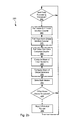
- FIGs. 2a-2b are flow diagrams showing methods for indirect storage medium failure in a data processing system in accordance with various embodiments of the present invention
- Fig. 3 shows a storage system with an indirect storage medium failure mechanism in accordance with one or more embodiments of the present invention.
- Fig. 4 depicts another data processing circuit including an indirect storage medium failure mechanism in accordance with some embodiments of the present invention.
- the present inventions are related to systems and methods for determining the health of a storage medium, and more particularly to systems and methods for indirectly predicting potential failures of a storage medium.
- Data processing circuit 100 includes an input sample buffer 110 that receives a data input 105.
- data input 105 is a series of data samples representing a sector of data sensed from a storage medium.
- a sample output 115 is provided by input sample buffer 110 to a channel detector circuit 120.
- Channel detector circuit 120 may be any channel detector known in the art.
- channel detector circuit 120 may be a soft output Viterbi algorithm (SOVA) detector as are known in the art. Based upon the disclosure provided herein, one of ordinary skill in the art will recognize other channel detectors that may be used in relation to different embodiments of the present invention.
- SOVA Soft output Viterbi algorithm
- Channel detector circuit 120 provides a detected output 125 corresponding to data input 105.
- Detected output 125 is provided to a decoding circuit 130.
- Decoding circuit 130 may be any decoding circuit known in the art.
- decoding circuit 130 may be a low density parity check (LDPC) decoder as are known in the art. Based upon the disclosure provided herein, one of ordinary skill in the art will recognize other decoders that may be used in relation to different embodiments of the present invention.
- Decoding circuit 130 provides a decoded output 135 to a soft/hard decision buffer 140. Decoded output 135 may include both soft and hard decision information as is known in the art.
- Soft/hard decision buffer may be any memory buffer that is capable of receiving soft and/or hard decision in preparation for providing a data output 145.
- decoded output 135 is provided to soft/hard decision buffer 140 when either decoding circuit 130 converges or a maximum number of iterations for data input 105 has been performed.
- decoding circuit 130 pulses data complete signal 181 when decoded output 135 is provided.
- one or more additional iterations may be performed in sequence by decoding circuit 130 using a local iteration feedback loop 137. Any time another local iteration is performed, a local start signal 185 is pulsed by decoding circuit 130. After a maximum number of local iterations, a decoded data output may be passed back to channel detector circuit 120 using a local iteration feedback loop 139 when the processing of data input 105 still fails to converge. Any time another global iteration is performed, a global start signal 183 is pulsed by decoding circuit 130. As there will always be at least one iteration through decoding circuit 130, local start signal 185 may not be pulsed for the first pass through decoding circuit, but only pulsed for each successive iteration. Alternatively, local start signal 185 may be pulsed for each iteration, with the additional count mathematically accounted for downstream.
- a data complete counter 180 is incremented each time data complete signal 181 is pulsed. Further, data complete counter 180 is reset whenever a reset signal 179 is asserted.
- a global loop counter 182 is incremented each time global start signal 183 is pulsed. Further, global loop counter 182 is reset whenever reset signal 179 is asserted.
- a local loop counter 184 is incremented each time local start signal 185 is pulsed. Further, local loop counter 182 is reset whenever reset signal 179 is asserted.
- a data complete value 191 from data complete counter 180, a global loop count value 193 from global loop counter 182, and a local loop count value 195 from local loop counter 184 are provided to a storage medium metrics computation module 190.
- Storage medium metrics computation module 190 uses the aforementioned count values to predict a potential failure of a medium from which data input 105 is derived. Further, storage medium metrics computation module 190 provides various statistics 197 that may be used to discern the health of a medium from which data input 105 is derived.
- Such statistics may include, for example, the mean number of times that a data set passes through a global loop (i.e., a channel detector circuit 120 and decoding circuit 130), and the mean number of times that a data set passes through a local loop (i.e., decoding circuit 130).
- the value of the aforementioned means may be calculated using, for example, histogramming, averaging, or least mean squared error method.
- the aforementioned equations assume that data complete counter 180, global loop counter 182 and local loop counter 184 are reset at the end of processing for each data set.
- reset 179 may be asserted at the end of processing a sector of data and after the respective count values are retrieved.
- local start signal 185 is not pulsed for the first local iteration through decoding circuit 130.
- the means are calculated each time data complete signal 181 is pulsed (i.e., at the end of processing each data set received via data input 105.
- a flow diagram 200 shows a method for obtaining various metrics that can be used for indirectly predicting storage medium failure in accordance with various embodiments of the present invention.
- a read data set is received (block 205).
- the read data set is a sector of data derived from a storage medium.
- a data detection process is performed on the read data (block 210). This data detection process may be any data detection known in the art such as, for example, a soft output Viterbi algorithm data detection.
- a local iteration count and a global iteration count are incremented indicating that at least one pass through the detection process and one pass through the decoding process are guaranteed to complete (block 215).
- a data decode is performed on the output from the data detector (block 220).
- the data decode may be done using any decoding algorithm known in the art. For example, the data decode may be done using an LDPC decoder. It is then determined whether the decoding process converged (i.e., resulted in the correct output) (block 225). Where the decoding process failed to converge (block 225), it is determined whether another local loop through the decoding circuit is to be used (block 230). This may be determined using determination mechanisms existing in the art. Where an additional local loop through the decoding process is to be performed (block 230), the local iteration counter is incremented to indicate the additional local loop (block 235) and the processes of blocks 220 through 230 are repeated using the output from the decoding process.
- the decoded data is provided to the data detector for performance of another data detection process (block 240).
- the global iteration counter is incremented indicating another global loop (block 245). The processes of blocks 220 through 230 are then repeated.
- the data resulting from the decoding process is provided as a data output (block 250), and the data complete count is incremented indicating a concluded data set (block 255).
- a metric update process is performed (block 201).
- the metric update process includes mathematically calculating various statistics and determining whether an increased potential for failure of the storage medium exists.
- a flow diagram 260 shows a method for performing the metric update process of block 201 of Fig. 2a in accordance with various embodiments of the present invention.
- the next data processing is complete (block 202)
- the local iteration count value from local iteration counter is pulled (block 265)
- the global iteration count value from the global iteration counter is pulled (block 275)
- the data complete value from the data complete counter is pulled (block 280).
- the mean of local iterations (block 285) and the mean of global iterations (block 290) are both calculated.
- the value of the aforementioned means may be calculated using, for example, histogramming, averaging, or least mean squared error method.
- the means are calculated each time a data set completes processing.
- Both of the means are then stored to memory (block 295). As such, the means may be accessed by any other process that may find use for them. It is then determined whether either of the calculated means is above a defined threshold (block 203). Where it is found that one or both of the mean values are above a defined threshold value (block 203), a potential failure is indicated (block 204).
- This report of a potential failure may be provided as, for example, an interrupt to a processor controlling access to the storage medium. In some cases, such an interrupt may cause a status check of the storage medium.
- Storage system 300 may be, for example, a hard disk drive.
- the indirect storage medium failure mechanism included as part of read channel 310 may be, but is not limited to, the system discussed in relation to Fig. 1 .
- the indirect storage medium failure mechanism included as part of read channel 310 may operate using the method described above in relation to Figs. 2a-2b .
- Storage system 300 also includes a preamplifier 370, an interface controller 320, a hard disk controller 366, a motor controller 368, a spindle motor 372, a disk platter 378, and a read/write head 376.
- Interface controller 320 controls addressing and timing of data to/from disk platter 378.
- the data on disk platter 378 consists of groups of magnetic signals that may be detected by read/write head assembly 376 when the assembly is properly positioned over disk platter 378.
- disk platter 378 includes magnetic signals recorded in accordance with a perpendicular recording scheme. For example, the magnetic signals may be recorded as either longitudinal or perpendicular recorded signals.
- read/write head assembly 376 is accurately positioned by motor controller 368 over a desired data track on disk platter 378.
- the appropriate data track is defined by an address received via interface controller 320.
- Motor controller 368 both positions read/write head assembly 376 in relation to disk platter 378 and drives spindle motor 372 by moving read/write head assembly to the proper data track on disk platter 378 under the direction of hard disk controller 366.
- Spindle motor 372 spins disk platter 378 at a determined spin rate (RPMs).
- RPMs spin rate
- the sensed magnetic signals are provided as a continuous, minute analog signal representative of the magnetic data on disk platter 378.
- This minute analog signal is transferred from read/write head assembly 376 to read channel module 364 via preamplifier 370.
- Preamplifier 370 is operable to amplify the minute analog signals accessed from disk platter 378.
- read channel module 310 decodes and digitizes the received analog signal to recreate the information originally written to disk platter 378.
- a write operation is substantially the opposite of the preceding read operation with write data 301 being provided to read channel module 310. This data is then encoded and written to disk platter 378.
- FIG. 4 another data processing circuit 400 including an indirect storage medium failure mechanism 499 (i.e., a health detection circuit) is shown in accordance with some embodiments of the present invention.
- data processing circuit 400 includes a data input 404 that is fed to a channel detector 408.
- Channel detector 408 may be any type of channel detector known in the art including, but not limited to, a soft output Viterbi algorithm detector (SOVA) or a maximum a posteriori (MAP) detector. Based on the disclosure provided herein, one of ordinary skill in the art will recognize a variety of channel detectors that may be used in accordance with different embodiments of the present invention.
- SOVA soft output Viterbi algorithm detector
- MAP maximum a posteriori
- data input 404 is provided to an input data buffer 412 that is designed to hold a number of data sets received from data input 404.
- data sets are a sector of data from a storage medium.
- the size of input data buffer 412 may be selected to provide sufficient buffering such that a data set input via data input 404 remains available at least until a first iteration processing of that same data set is complete and the processed data is available in a ping pong buffer 448 (i.e., a queuing buffer) as more fully described below.
- Input data buffer 412 provides the data sets to a channel detector 416.
- channel detector 416 may be any type of channel detector known in the art including, but not limited to, a SOVA detector or a MAP detector. Again, based on the disclosure provided herein, one of ordinary skill in the art will recognize a variety of channel detectors that may be used in accordance with different embodiments of the present invention.
- the output of both channel detector 408 and channel detector 416 are provided to an interleaver circuit 428 via a multiplexer 420. Such outputs may be, for example, log likelihood ratio values.
- Interleaver circuit 428 interleaves the output of channel detector 408 and separately interleaves the output of channel detector 416 using two ping pong buffers 424, 432.
- One of the buffers in ping pong buffer 424 holds the result of a prior interleaving process of the output from channel detector 408 and is unloaded to an LDPC decoder 436, while the other buffer of ping pong buffer 424 holds a data set from channel detector 408 that is currently being interleaved.
- one of the buffers in ping pong buffer 432 holds the result of a prior interleaving process of the output from channel detector 416 and is unloaded to LDPC decoder 436, while the other buffer of ping pong buffer 424 holds a data set from channel detector 416 that is currently being interleaved.
- LDPC decoder 436 is capable of decoding one or more data sets simultaneously.
- LDPC decoder 436 may be designed to decode an interleaved data set from ping pong buffer 424, or an interleaved data set from ping pong buffer 432, or to decode interleaved data sets from ping pong buffer 424 and ping pong buffer 432 simultaneously.
- the decoded data is either provided as a hard decision output 440 and/or to a de-interleaver circuit 444 that uses ping pong buffer 448 to de-interleave the decoded data and to provide the de-interleaved data as an input to channel detector 416.
- Hard decision output 440 is provided to a de-interleaver circuit 456 that de-interleaves hard decision output 440 and stores the de-interleaved result in an output data buffer 460.
- de-interleaver circuit 456 provides the de-interleaved data stored in output data buffer 460 as an output 470.
- Hard output 440 is provided from LDPC decoder 436 whenever the data processed by LDPC decoder 436 converges or whenever there is insufficient buffering in output data buffer 460.
- LDPC decoder 436 is capable of performing one or more local iterations (i.e., processing through LDPC decoder 436). Each time one of the local iterations is started, LDPC decoder 436 pulses a local start signal 485. Further, each time decoded data is placed in ping pong buffer 448 requiring another pass through channel detector 416 and LDPC decoder 436, a global start signal 483 is pulsed by LDPC decoder 436. In addition, each time hard decision data 440 is provided to output data buffer 460, a data complete signal 481 is pulsed by LDPC decoder 436.
- Indirect storage medium failure mechanism 499 includes a data complete counter 480 that is incremented each time data complete signal 481 is pulsed. Further, data complete counter 480 is reset whenever a reset signal 479 is asserted. A global loop counter 482 is incremented each time global start signal 483 is pulsed. Further, global loop counter 482 is reset whenever reset signal 479 is asserted. A local loop counter 484 is incremented each time local start signal 485 is pulsed. Further, local loop counter 482 is reset whenever reset signal 479 is asserted.
- a data complete value 491 from data complete counter 480, a global loop count value 493 from global loop counter 482, and a local loop count value 495 from local loop counter 484 are provided to a storage medium metrics computation module 490.
- Storage medium metrics computation module 490 uses the aforementioned count values to predict a potential failure of a medium from which data input 404 is derived. Further, storage medium metrics computation module 490 provides various statistics 497 that may be used to discern the health of a medium from which data input 404 is derived.
- Such statistics may include, for example, the mean number of times that a data set passes through a global loop (i.e., a channel detector circuit 408/416 and LDPC decoder circuit 436), and the mean number of times that a data set passes through a local loop (i.e., decoding circuit 436).
- the value of the aforementioned means may be calculated using, for example, histogramming, averaging, or least mean squared error method.
- the means are calculated each time data complete signal 481 is pulsed (i.e., at the end of processing each data set received via data input 404.
- Indirect storage medium failure mechanism 499 is operable to provide statistics 497 indicating operational status of data processing circuit 400 and indirectly indicating the health of a medium from which input 404 is derived.
- a number of local loop iterations and/or global loop iterations may be used for decoding each data set (e.g., each data sector of a storage medium).
- a count of the number of loops executed for each data set is maintained individually. This allows for a determination of the health of the particular region from which the data set is taken.
- Such individual data set counters can be realized for storing count values with the data set to which they correspond in ping pong buffer 448. When the data is again pulled from ping pong buffer 448 for additional processing, the count values associated with the respective data set are loaded into the counters (i.e., global loop counter 482 and local loop counter 484) and are incremented in accordance with any additional processing that is applied.
- the data set is to be processed further, it is put back into ping pong buffer 448.
- the global loop values and the local loop value are also put back into a corresponding location in ping pong buffer 448.
- the accumulated local loop count and global loop count are tested to provide statistics associated with the location on the storage medium from which the particular data set was derived. This process of accumulating global and local loop counts is repeated for each data set individually.
- a similar storage medium failure mechanism 499 may be applied to other data processing circuits.
- a storage medium failure mechanism 499 generating the various statistics may be applied to the data processing circuits disclosed in US Pat. No. 12/114,462 entitled “Systems and Methods for Queue Based Data Detection and Decoding", and filed May 2, 2008 by Yang et al. The entirety of the aforementioned patent application is incorporated herein by reference for all purposes.
- the invention provides novel systems, devices, methods and arrangements for determining storage medium health. While detailed descriptions of one or more embodiments of the invention have been given above, various alternatives, modifications, and equivalents will be apparent to those skilled in the art without varying from the spirit of the invention. Further, techniques discussed herein may be applied to analog to digital converters as well. Therefore, the above description should not be taken as limiting the scope of the invention, which is defined by the appended claims.
Landscapes
- Engineering & Computer Science (AREA)
- Physics & Mathematics (AREA)
- Probability & Statistics with Applications (AREA)
- Theoretical Computer Science (AREA)
- Signal Processing (AREA)
- Detection And Correction Of Errors (AREA)
- Signal Processing For Digital Recording And Reproducing (AREA)
- Error Detection And Correction (AREA)
Abstract
Description
- The present inventions are related to systems and methods for determining the health of a storage medium, and more particularly to systems and methods for indirectly predicting potential failures of a storage medium.
- A typical storage device includes a storage medium where information is stored for retrieval at a later point. Over time, the storage medium and/or other circuits and modules of the storage device may degrade leading to possible failures. For hard disk drives, failure rates are often discussed as sector failure rates with an acceptable failure rate being less than e-15. Such small failure rates are often difficult to detect, and even where detectable, often require an extended period of time for measurement. In some cases, this extended period makes determination of possible failure impractical.
- Hence, for at least the aforementioned reasons, there exists a need in the art for advanced systems and methods for predicting failure of a storage medium.
- The present inventions are related to systems and methods for determining the health of a storage medium, and more particularly to systems and methods for indirectly predicting potential failures of a storage medium.
- Various embodiments of the present invention provide storage devices that include a storage medium and a data processing circuit. The data processing circuit receives a data set derived from the storage medium. The data processing circuit includes a data detector circuit, a data decoder circuit, and a health detection circuit. The data detector circuit receives the data set and provides a detected output. The data decoder circuit receives a derivative of the detected output and provides a decoded output. In some cases, the derivative of the detected output is an interleaved version of the detected output. The health detection circuit receives an indication of a number of times that the data set is processed through the combination of the data detector circuit and the data decoder circuit. The health detection circuit generates an indirect health status of the storage medium based at least in part on the number of times that the data set is processed through the combination of the data detector circuit and the data decoder circuit. This combination of processing through the combination may be referred to as a global iteration.
- In some instances of the aforementioned embodiments, the health detection circuit includes a global loop counter that is incremented when the data set is processed through the combination of the data detector circuit and the data decoder circuit. In such cases, the number of times that the data set is processed through the combination of the data detector circuit and the data decoder circuit is a global loop count value provided by the global loop counter. In various cases, the indirect health status of the storage medium includes a mean of the global loop count value derived after processing a plurality of data sets. In particular cases, the mean of the global loop count value is calculated in accordance with the following equation:

where i indicates an instant in time corresponding to a global loop count value and µ is a scalar value. - In one or more instances of the aforementioned embodiments, the data decoder circuit is operable to process the data set a plurality of times in sequence. In such cases, the health detection circuit may include a local loop counter that is incremented when the data set is processed through the data decoder circuit. In some such cases, the health detection circuit receives an indication of a number of times that the data set is processed through the data decoder circuit, and the health detection circuit generates an indirect health status of the storage medium based at least in part on the number of times that the data set is processed through the data decoder circuit. The number of times that the data set is processed through the data decoder circuit is a local loop count value provided by the local loop counter. In some cases, the indirect health status of the storage medium includes a mean of the local loop count value derived after processing a plurality of data sets. In such cases, the mean of the local loop count value may be calculated in accordance with the following equation:

where i indicates an instant in time corresponding to a local loop count value and µ is a scalar value. - Other embodiments of the present invention provide storage devices that include a storage medium and a data processing circuit. The data processing circuit receives a data set derived from the storage medium. The data processing circuit includes: a data decoder circuit and a health detection circuit. The data decoder circuit receives a derivative of the data set and provides a decoded output. The data decoder circuit is operable to process the derivative of the data set a plurality of times in sequence. The health detection circuit receives an indication of a number of times that the data set is processed through the data decoder circuit, and the health detection circuit generates an indirect health status of the storage medium based at least in part on the number of times that the data set is processed through the data decoder circuit. In some cases, the health status circuit includes a local loop counter that is incremented when the data set is processed through the data decoder circuit. The number of times that the data set is processed through the data decoder circuit is a local loop count value provided by the local loop counter. In particular cases, the indirect health status of the storage medium includes a mean of the local loop count value derived after processing a plurality of data sets.
- In various instances of the aforementioned embodiments, the data processing circuit further includes a data detector circuit. The data detector circuit receives the data set and provides a detected output. In such cases, the derivative of the data set is a derivative of the detected output. In some cases, the health detection circuit includes a global loop counter that is incremented when the data set is processed through the combination of the data detector circuit and the data decoder circuit. The number of times that the data set is processed through the combination of the data detector circuit and the data decoder circuit is a global loop count value provided by the global loop counter. In such cases, the indirect health status of the storage medium includes a mean of the global loop count value derived after processing a plurality of data sets.
- Yet other embodiments of the present invention provide data processing circuits that include: a first data detector circuit, a second data detector circuit, a data decoder circuit, and a health detection circuit. The first data detector circuit is operable to perform a data detection on a first input data set at a first time and on a second input data set at a second time. The first input data set and the second input data set are derived from a storage medium. The data decoder circuit is operable to receive a derivation of an output from the first data detector circuit corresponding to the first data set, an output from the first data detector circuit corresponding to the second data set, and a derivation of an output from the second data detector circuit. The data decoder circuit is further operable to process a given data set a plurality of times in sequence. The second data detector circuit is operable to perform a data detection on the first input data set using the output of the data decoder circuit corresponding to the first input data set at a third time only if the output of the decoder failed to converge. The third time is subsequent to the first time and to the second time. The health detection circuit receives an indication of a number of times that the data set is processed through the data decoder circuit, and generates an indirect health status of the storage medium based at least in part on the number of times that the data set is processed through the data decoder circuit.
- This summary provides only a general outline of some embodiments of the invention. Many other objects, features, advantages and other embodiments of the invention will become more fully apparent from the following detailed description, the appended claims and the accompanying drawings.
- A further understanding of the various embodiments of the present invention may be realized by reference to the figures which are described in remaining portions of the specification. In the figures, like reference numerals are used throughout several drawings to refer to similar components. In some instances, a sub-label consisting of a lower case letter is associated with a reference numeral to denote one of multiple similar components. When reference is made to a reference numeral without specification to an existing sub-label, it is intended to refer to all such multiple similar components.
-
Fig. 1 shows a data processing circuit including an indirect storage medium failure mechanism in accordance with some embodiments of the present invention; -
Figs. 2a-2b are flow diagrams showing methods for indirect storage medium failure in a data processing system in accordance with various embodiments of the present invention; -
Fig. 3 shows a storage system with an indirect storage medium failure mechanism in accordance with one or more embodiments of the present invention; and -
Fig. 4 depicts another data processing circuit including an indirect storage medium failure mechanism in accordance with some embodiments of the present invention. - The present inventions are related to systems and methods for determining the health of a storage medium, and more particularly to systems and methods for indirectly predicting potential failures of a storage medium.
- Turning to
Fig. 1 , adata processing circuit 100 including an indirect storagemedium failure mechanism 199 is shown in accordance with some embodiments of the present invention.Data processing circuit 100 includes aninput sample buffer 110 that receives adata input 105. In some cases,data input 105 is a series of data samples representing a sector of data sensed from a storage medium. Based upon the disclosure provided herein, one of ordinary skill in the art will recognize other data inputs and sources thereof that may be used in relation to different embodiments of the present invention. Asample output 115 is provided byinput sample buffer 110 to achannel detector circuit 120.Channel detector circuit 120 may be any channel detector known in the art. As an example,channel detector circuit 120 may be a soft output Viterbi algorithm (SOVA) detector as are known in the art. Based upon the disclosure provided herein, one of ordinary skill in the art will recognize other channel detectors that may be used in relation to different embodiments of the present invention. -
Channel detector circuit 120 provides a detectedoutput 125 corresponding todata input 105. Detectedoutput 125 is provided to adecoding circuit 130. Decodingcircuit 130 may be any decoding circuit known in the art. As an example,decoding circuit 130 may be a low density parity check (LDPC) decoder as are known in the art. Based upon the disclosure provided herein, one of ordinary skill in the art will recognize other decoders that may be used in relation to different embodiments of the present invention. Decodingcircuit 130 provides a decodedoutput 135 to a soft/hard decision buffer 140.Decoded output 135 may include both soft and hard decision information as is known in the art. Soft/hard decision buffer may be any memory buffer that is capable of receiving soft and/or hard decision in preparation for providing adata output 145. In some cases, decodedoutput 135 is provided to soft/hard decision buffer 140 when eitherdecoding circuit 130 converges or a maximum number of iterations fordata input 105 has been performed. In addition to providingdecoded output 135 to soft/hard decision buffer 140,decoding circuit 130 pulses datacomplete signal 181 when decodedoutput 135 is provided. - Where processing of
data input 105 fails to converge, one or more additional iterations may be performed in sequence by decodingcircuit 130 using a localiteration feedback loop 137. Any time another local iteration is performed, alocal start signal 185 is pulsed by decodingcircuit 130. After a maximum number of local iterations, a decoded data output may be passed back tochannel detector circuit 120 using a localiteration feedback loop 139 when the processing ofdata input 105 still fails to converge. Any time another global iteration is performed, aglobal start signal 183 is pulsed by decodingcircuit 130. As there will always be at least one iteration throughdecoding circuit 130,local start signal 185 may not be pulsed for the first pass through decoding circuit, but only pulsed for each successive iteration. Alternatively,local start signal 185 may be pulsed for each iteration, with the additional count mathematically accounted for downstream. - A data
complete counter 180 is incremented each time datacomplete signal 181 is pulsed. Further, datacomplete counter 180 is reset whenever areset signal 179 is asserted. Aglobal loop counter 182 is incremented each timeglobal start signal 183 is pulsed. Further,global loop counter 182 is reset wheneverreset signal 179 is asserted. Alocal loop counter 184 is incremented each timelocal start signal 185 is pulsed. Further,local loop counter 182 is reset wheneverreset signal 179 is asserted. - A data
complete value 191 from datacomplete counter 180, a globalloop count value 193 fromglobal loop counter 182, and a localloop count value 195 fromlocal loop counter 184 are provided to a storage mediummetrics computation module 190. Storage mediummetrics computation module 190 uses the aforementioned count values to predict a potential failure of a medium from whichdata input 105 is derived. Further, storage mediummetrics computation module 190 providesvarious statistics 197 that may be used to discern the health of a medium from whichdata input 105 is derived. Such statistics may include, for example, the mean number of times that a data set passes through a global loop (i.e., achannel detector circuit 120 and decoding circuit 130), and the mean number of times that a data set passes through a local loop (i.e., decoding circuit 130). The value of the aforementioned means may be calculated using, for example, histogramming, averaging, or least mean squared error method. As an example, the means may be calculated in accordance with the following equations:

where i indicates an instant in time where the values are calculated and µ is a small scalar value that is selected to limit the change that can occur at any time. The aforementioned equations assume that datacomplete counter 180,global loop counter 182 andlocal loop counter 184 are reset at the end of processing for each data set. Thus, for example, reset 179 may be asserted at the end of processing a sector of data and after the respective count values are retrieved. In such cases,local start signal 185 is not pulsed for the first local iteration throughdecoding circuit 130. In some embodiments of the present invention, the means are calculated each time datacomplete signal 181 is pulsed (i.e., at the end of processing each data set received viadata input 105. As another example, the means may be calculated as simple averages in accordance with the following equations:

where i indicates an instant in time where the values are calculated. For these equations, the count values from datacomplete counter 180,global loop counter 182 andlocal loop counter 184 are not necessarily reset at the end of processing of a data set. - Turning to
Fig. 2a , a flow diagram 200 shows a method for obtaining various metrics that can be used for indirectly predicting storage medium failure in accordance with various embodiments of the present invention. Following flow diagram 200, a read data set is received (block 205). In some cases, the read data set is a sector of data derived from a storage medium. Based upon the disclosure provided herein, one of ordinary skill in the art will recognize a variety of data sets that may be processed in accordance with different embodiments of the present invention. A data detection process is performed on the read data (block 210). This data detection process may be any data detection known in the art such as, for example, a soft output Viterbi algorithm data detection. It should be noted that other channel detectors may be used in relation to different embodiments of the present invention. A local iteration count and a global iteration count are incremented indicating that at least one pass through the detection process and one pass through the decoding process are guaranteed to complete (block 215). - A data decode is performed on the output from the data detector (block 220). The data decode may be done using any decoding algorithm known in the art. For example, the data decode may be done using an LDPC decoder. It is then determined whether the decoding process converged (i.e., resulted in the correct output) (block 225). Where the decoding process failed to converge (block 225), it is determined whether another local loop through the decoding circuit is to be used (block 230). This may be determined using determination mechanisms existing in the art. Where an additional local loop through the decoding process is to be performed (block 230), the local iteration counter is incremented to indicate the additional local loop (block 235) and the processes of
blocks 220 through 230 are repeated using the output from the decoding process. - Alternatively, where an additional loop through the decoding process is not called for (block 230), the decoded data is provided to the data detector for performance of another data detection process (block 240). In addition to performing the data detection (block 240), the global iteration counter is incremented indicating another global loop (block 245). The processes of
blocks 220 through 230 are then repeated. - Where the data converges (or a timeout condition is exceeded) (block 225), the data resulting from the decoding process is provided as a data output (block 250), and the data complete count is incremented indicating a concluded data set (block 255). With the new metrics (global iteration count, local iteration count, and data complete count), a metric update process is performed (block 201). The metric update process includes mathematically calculating various statistics and determining whether an increased potential for failure of the storage medium exists.
- Turning to
Fig. 2b , a flow diagram 260 shows a method for performing the metric update process ofblock 201 ofFig. 2a in accordance with various embodiments of the present invention. Following flow diagram 260, it is determined if the next data processing has completed (block 202). In some cases, this block is essentially the same asblocks 225 through 255 ofFig. 2a . Where the next data processing is complete (block 202), the local iteration count value from local iteration counter is pulled (block 265), the global iteration count value from the global iteration counter is pulled (block 275), and the data complete value from the data complete counter is pulled (block 280). - Using the aforementioned information, the mean of local iterations (block 285) and the mean of global iterations (block 290) are both calculated. The value of the aforementioned means may be calculated using, for example, histogramming, averaging, or least mean squared error method. As an example, the means may be calculated in accordance with the following equations:


where i indicates an instant in time where the values are calculated and µ is a small scalar value that is selected to limit the change that can occur at any time. In some embodiments of the present invention, the means are calculated each time a data set completes processing. As another example, the means may be calculated as simple averages in accordance with the following equations:

where i indicates an instant in time where the values are calculated. - Both of the means are then stored to memory (block 295). As such, the means may be accessed by any other process that may find use for them. It is then determined whether either of the calculated means is above a defined threshold (block 203). Where it is found that one or both of the mean values are above a defined threshold value (block 203), a potential failure is indicated (block 204). This report of a potential failure may be provided as, for example, an interrupt to a processor controlling access to the storage medium. In some cases, such an interrupt may cause a status check of the storage medium.
- Turning to
Fig. 3 , astorage system 300 including aread channel circuit 310 with an indirect storage medium failure mechanism is shown in accordance with one or more embodiments of the present invention.Storage system 300 may be, for example, a hard disk drive. The indirect storage medium failure mechanism included as part ofread channel 310 may be, but is not limited to, the system discussed in relation toFig. 1 . In some cases, the indirect storage medium failure mechanism included as part ofread channel 310 may operate using the method described above in relation toFigs. 2a-2b . -
Storage system 300 also includes apreamplifier 370, aninterface controller 320, ahard disk controller 366, amotor controller 368, aspindle motor 372, adisk platter 378, and a read/write head 376.Interface controller 320 controls addressing and timing of data to/fromdisk platter 378. The data ondisk platter 378 consists of groups of magnetic signals that may be detected by read/write head assembly 376 when the assembly is properly positioned overdisk platter 378. In one embodiment,disk platter 378 includes magnetic signals recorded in accordance with a perpendicular recording scheme. For example, the magnetic signals may be recorded as either longitudinal or perpendicular recorded signals. - In a typical read operation, read/
write head assembly 376 is accurately positioned bymotor controller 368 over a desired data track ondisk platter 378. The appropriate data track is defined by an address received viainterface controller 320.Motor controller 368 both positions read/write head assembly 376 in relation todisk platter 378 and drivesspindle motor 372 by moving read/write head assembly to the proper data track ondisk platter 378 under the direction ofhard disk controller 366.Spindle motor 372 spinsdisk platter 378 at a determined spin rate (RPMs). Once read/write head assembly 378 is positioned adjacent the proper data track, magnetic signals representing data ondisk platter 378 are sensed by read/write head assembly 376 asdisk platter 378 is rotated byspindle motor 372. The sensed magnetic signals are provided as a continuous, minute analog signal representative of the magnetic data ondisk platter 378. This minute analog signal is transferred from read/write head assembly 376 to read channel module 364 viapreamplifier 370.Preamplifier 370 is operable to amplify the minute analog signals accessed fromdisk platter 378. In turn, readchannel module 310 decodes and digitizes the received analog signal to recreate the information originally written todisk platter 378. A write operation is substantially the opposite of the preceding read operation withwrite data 301 being provided to readchannel module 310. This data is then encoded and written todisk platter 378. - Turning to
Fig. 4 , anotherdata processing circuit 400 including an indirect storage medium failure mechanism 499 (i.e., a health detection circuit) is shown in accordance with some embodiments of the present invention. Along with indirect storagemedium failure mechanism 499,data processing circuit 400 includes adata input 404 that is fed to achannel detector 408.Channel detector 408 may be any type of channel detector known in the art including, but not limited to, a soft output Viterbi algorithm detector (SOVA) or a maximum a posteriori (MAP) detector. Based on the disclosure provided herein, one of ordinary skill in the art will recognize a variety of channel detectors that may be used in accordance with different embodiments of the present invention. In addition,data input 404 is provided to aninput data buffer 412 that is designed to hold a number of data sets received fromdata input 404. In some embodiments of the present invention, such data sets are a sector of data from a storage medium. The size ofinput data buffer 412 may be selected to provide sufficient buffering such that a data set input viadata input 404 remains available at least until a first iteration processing of that same data set is complete and the processed data is available in a ping pong buffer 448 (i.e., a queuing buffer) as more fully described below.Input data buffer 412 provides the data sets to achannel detector 416. Similar tochannel detector 408,channel detector 416 may be any type of channel detector known in the art including, but not limited to, a SOVA detector or a MAP detector. Again, based on the disclosure provided herein, one of ordinary skill in the art will recognize a variety of channel detectors that may be used in accordance with different embodiments of the present invention. - The output of both
channel detector 408 andchannel detector 416 are provided to aninterleaver circuit 428 via amultiplexer 420. Such outputs may be, for example, log likelihood ratio values.Interleaver circuit 428 interleaves the output ofchannel detector 408 and separately interleaves the output ofchannel detector 416 using two ping pong buffers 424, 432. One of the buffers inping pong buffer 424 holds the result of a prior interleaving process of the output fromchannel detector 408 and is unloaded to anLDPC decoder 436, while the other buffer ofping pong buffer 424 holds a data set fromchannel detector 408 that is currently being interleaved. Similarly, one of the buffers inping pong buffer 432 holds the result of a prior interleaving process of the output fromchannel detector 416 and is unloaded toLDPC decoder 436, while the other buffer ofping pong buffer 424 holds a data set fromchannel detector 416 that is currently being interleaved. -
LDPC decoder 436 is capable of decoding one or more data sets simultaneously. As an example,LDPC decoder 436 may be designed to decode an interleaved data set fromping pong buffer 424, or an interleaved data set fromping pong buffer 432, or to decode interleaved data sets fromping pong buffer 424 andping pong buffer 432 simultaneously. The decoded data is either provided as ahard decision output 440 and/or to ade-interleaver circuit 444 that usesping pong buffer 448 to de-interleave the decoded data and to provide the de-interleaved data as an input tochannel detector 416. One of the buffers inping pong buffer 448 holds the result of a prior de-interleaving process and is unloaded tochannel detector 416, while the other buffer ofping pong buffer 448 holds a decoded data set currently being de-interleaved.Hard decision output 440 is provided to ade-interleaver circuit 456 that de-interleaveshard decision output 440 and stores the de-interleaved result in anoutput data buffer 460. Ultimately,de-interleaver circuit 456 provides the de-interleaved data stored inoutput data buffer 460 as anoutput 470.Hard output 440 is provided fromLDPC decoder 436 whenever the data processed byLDPC decoder 436 converges or whenever there is insufficient buffering inoutput data buffer 460. -
LDPC decoder 436 is capable of performing one or more local iterations (i.e., processing through LDPC decoder 436). Each time one of the local iterations is started,LDPC decoder 436 pulses alocal start signal 485. Further, each time decoded data is placed inping pong buffer 448 requiring another pass throughchannel detector 416 andLDPC decoder 436, aglobal start signal 483 is pulsed byLDPC decoder 436. In addition, each timehard decision data 440 is provided tooutput data buffer 460, a datacomplete signal 481 is pulsed byLDPC decoder 436. Indirect storagemedium failure mechanism 499 includes a datacomplete counter 480 that is incremented each time datacomplete signal 481 is pulsed. Further, datacomplete counter 480 is reset whenever areset signal 479 is asserted. Aglobal loop counter 482 is incremented each timeglobal start signal 483 is pulsed. Further,global loop counter 482 is reset wheneverreset signal 479 is asserted. Alocal loop counter 484 is incremented each timelocal start signal 485 is pulsed. Further,local loop counter 482 is reset wheneverreset signal 479 is asserted. - A data
complete value 491 from datacomplete counter 480, a globalloop count value 493 fromglobal loop counter 482, and a localloop count value 495 fromlocal loop counter 484 are provided to a storage mediummetrics computation module 490. Storage mediummetrics computation module 490 uses the aforementioned count values to predict a potential failure of a medium from whichdata input 404 is derived. Further, storage mediummetrics computation module 490 providesvarious statistics 497 that may be used to discern the health of a medium from whichdata input 404 is derived. Such statistics may include, for example, the mean number of times that a data set passes through a global loop (i.e., achannel detector circuit 408/416 and LDPC decoder circuit 436), and the mean number of times that a data set passes through a local loop (i.e., decoding circuit 436). The value of the aforementioned means may be calculated using, for example, histogramming, averaging, or least mean squared error method. As an example, the means may be calculated in accordance with the following equations:

where i indicates an instant in time where the values are calculated and µ is a small scalar value that is selected to limit the change that can occur at any time. In some embodiments of the present invention, the means are calculated each time datacomplete signal 481 is pulsed (i.e., at the end of processing each data set received viadata input 404. As another example, the means may be calculated as simple averages in accordance with the following equations:

where i indicates an instant in time where the values are calculated. Indirect storagemedium failure mechanism 499 is operable to providestatistics 497 indicating operational status ofdata processing circuit 400 and indirectly indicating the health of a medium from whichinput 404 is derived. - Of note, a number of local loop iterations and/or global loop iterations may be used for decoding each data set (e.g., each data sector of a storage medium). A count of the number of loops executed for each data set is maintained individually. This allows for a determination of the health of the particular region from which the data set is taken. Such individual data set counters can be realized for storing count values with the data set to which they correspond in
ping pong buffer 448. When the data is again pulled fromping pong buffer 448 for additional processing, the count values associated with the respective data set are loaded into the counters (i.e.,global loop counter 482 and local loop counter 484) and are incremented in accordance with any additional processing that is applied. Where the data set is to be processed further, it is put back intoping pong buffer 448. At that time, the global loop values and the local loop value are also put back into a corresponding location inping pong buffer 448. When the data set is finally written out ashard decision data 440, the accumulated local loop count and global loop count are tested to provide statistics associated with the location on the storage medium from which the particular data set was derived. This process of accumulating global and local loop counts is repeated for each data set individually. - It should be noted that a similar storage
medium failure mechanism 499 may be applied to other data processing circuits. For example, a storagemedium failure mechanism 499 generating the various statistics may be applied to the data processing circuits disclosed inUS Pat. No. 12/114,462 - In conclusion, the invention provides novel systems, devices, methods and arrangements for determining storage medium health. While detailed descriptions of one or more embodiments of the invention have been given above, various alternatives, modifications, and equivalents will be apparent to those skilled in the art without varying from the spirit of the invention. Further, techniques discussed herein may be applied to analog to digital converters as well. Therefore, the above description should not be taken as limiting the scope of the invention, which is defined by the appended claims.
Claims (15)
- A storage device, wherein the storage device comprises:a storage medium; anda data processing circuit, wherein the data processing circuit receives a data set derived from the storage medium, and wherein the data processing circuit includes:a data detector circuit, wherein the data detector circuit receives the data set and provides a detected output;a data decoder circuit, wherein the data decoder circuit receives a derivative of the detected output and provides a decoded output; anda health detection circuit, wherein the health detection circuit receives an indication of a number of times that the data set is processed through the combination of the data detector circuit and the data decoder circuit, and wherein the health detection circuit generates an indirect health status of the storage medium based at least in part on the number of times that the data set is processed through the combination of the data detector circuit and the data decoder circuit.
- The storage device of claim 1, wherein the health detection circuit includes a global loop counter that is incremented when the data set is processed through the combination of the data detector circuit and the data decoder circuit, and wherein the number of times that the data set is processed through the combination of the data detector circuit and the data decoder circuit is a global loop count value provided by the global loop counter.
- The storage device of claim 2, wherein the indirect health status of the storage medium includes a mean of the global loop count value derived after processing a plurality of data sets.
- The storage device of claim 2, wherein the data decoder circuit is operable to process the data set a plurality of times in sequence, and wherein the health detection circuit includes a local loop counter that is incremented when the data set is processed through the data decoder circuit.
- The storage device of claim 4, wherein the health detection circuit receives an indication of a number of times that the data set is processed through the data decoder circuit, and wherein the health detection circuit generates an indirect health status of the storage medium based at least in part on the number of times that the data set is processed through the data decoder circuit, and wherein the number of times that the data set is processed through the data decoder circuit is a local loop count value provided by the local loop counter.
- A storage device, wherein the storage device comprises:a storage medium; anda data processing circuit, wherein the data processing circuit receives a data set derived from the storage medium, and wherein the data processing circuit includes:a data decoder circuit, wherein the data decoder circuit receives a derivative of the data set and provides a decoded output, and wherein the data decoder circuit is operable to process the derivative of the data set a plurality of times in sequence; anda health detection circuit, wherein the health detection circuit receives an indication of a number of times that the data set is processed through the data decoder circuit, and wherein the health detection circuit generates an indirect health status of the storage medium based at least in part on the number of times that the data set is processed through the data decoder circuit.
- The storage device of claim 6, wherein the health detection circuit includes a local loop counter that is incremented when the data set is processed through the data decoder circuit, and wherein the number of times that the data set is processed through the data decoder circuit is a local loop count value provided by the local loop counter.
- The storage device of claim 7, wherein the indirect health status of the storage medium includes a mean of the local loop count value derived after processing a plurality of data sets.
- The storage device of claim 6, wherein the data processing circuit further includes:a data detector circuit, wherein the data detector circuit receives the data set and provides a detected output, and wherein the derivative of the data set is a derivative of the detected output.
- A data processing circuit, the data processing circuit comprising:a first data detector circuit, wherein the first data detector circuit is operable to perform a data detection on a first input data set at a first time and on a second input data set at a second time, and wherein the first input data set and the second input data set are derived from a storage medium;a second data detector circuit;a data decoder circuit, wherein the data decoder circuit is operable to receive a derivation of an output from the first data detector circuit corresponding to the first data set, an output from the first data detector circuit corresponding to the second data set, and a derivation of an output from the second data detector circuit; and wherein the data decoder circuit is operable to process a given data set a plurality of times in sequence;wherein the second data detector circuit is operable to perform a data detection on the first input data set using the output of the data decoder circuit corresponding to the first input data set at a third time only if the output of the decoder failed to converge, and wherein the third time is subsequent to the first time and to the second time; anda health detection circuit, wherein the health detection circuit receives an indication of a number of times that the data set is processed through the data decoder circuit, and wherein the health detection circuit generates an indirect health status of the storage medium based at least in part on the number of times that the data set is processed through the data decoder circuit.
- The data processing circuit of claim 10, wherein the health detection circuit includes a local loop counter that is incremented when the data set is processed through the data decoder circuit, and wherein the number of times that the data set is processed through the data decoder circuit is a local loop count value provided by the local loop counter.
- The data processing circuit of claim 11, wherein the indirect health status of the storage medium includes a mean of the local loop count value derived after processing a plurality of data sets.
- The data processing circuit of claim 12, wherein the mean of the local loop count value is calculated in accordance with the following equation:

where i indicates an instant in time corresponding to a local loop count value and
µ is a scalar value. - The data processing circuit of claim 10, wherein the health detection circuit includes a global loop counter that is incremented when the data set is processed through a combination of the data decoder circuit and one of the first data detector circuit and the second data detector circuit, and wherein the number of times that the data set is processed through the combination is a global loop count value provided by the global loop counter.
- The data processing circuit of claim 14, wherein the indirect health status of the storage medium includes a mean of the global loop count value derived after processing a plurality of data sets.
Applications Claiming Priority (1)
| Application Number | Priority Date | Filing Date | Title |
|---|---|---|---|
| US12/425,824 US8347155B2 (en) | 2009-04-17 | 2009-04-17 | Systems and methods for predicting failure of a storage medium |
Publications (2)
| Publication Number | Publication Date |
|---|---|
| EP2242054A2 true EP2242054A2 (en) | 2010-10-20 |
| EP2242054A3 EP2242054A3 (en) | 2011-05-18 |
Family
ID=41679283
Family Applications (1)
| Application Number | Title | Priority Date | Filing Date |
|---|---|---|---|
| EP09170117A Withdrawn EP2242054A3 (en) | 2009-04-17 | 2009-09-11 | Systems and methods for predicting failure of a stroage medium |
Country Status (6)
| Country | Link |
|---|---|
| US (1) | US8347155B2 (en) |
| EP (1) | EP2242054A3 (en) |
| JP (1) | JP5746474B2 (en) |
| KR (1) | KR101602501B1 (en) |
| CN (1) | CN101866672B (en) |
| TW (1) | TWI459382B (en) |
Cited By (11)
| Publication number | Priority date | Publication date | Assignee | Title |
|---|---|---|---|---|
| EP2568611A3 (en) * | 2011-09-08 | 2013-07-10 | LSI Corporation | Systems and methods for non binary decoding biasing control |
| EP2665190A1 (en) * | 2012-05-17 | 2013-11-20 | LSI Corporation | Decoding of non-binary codes with symbol re-grouping |
| EP2665191A1 (en) * | 2012-05-17 | 2013-11-20 | LSI Corporation | Systems and methods for dual binary and non-binary decoding |
| US8762807B2 (en) | 2011-12-15 | 2014-06-24 | Lsi Corporation | Systems and methods for out of order processing in a data retry |
| US8910005B2 (en) | 2012-12-03 | 2014-12-09 | Lsi Corporation | Systems and methods for selective retry data retention processing |
| US8949696B2 (en) | 2013-02-19 | 2015-02-03 | Lsi Corporation | Systems and methods for trapping set disruption |
| US9190104B2 (en) | 2012-12-13 | 2015-11-17 | Avago Technologies General Ip (Singapore) Pte. Ltd. | Systems and methods for data retry using averaging process |
| US9323625B2 (en) | 2013-11-12 | 2016-04-26 | Avago Technologies General Ip (Singapore) Pte. Ltd. | Systems and methods for lost synchronization data set reprocessing |
| US9385758B2 (en) | 2014-01-02 | 2016-07-05 | Avago Technologies General Ip (Singapore) Pte. Ltd. | Systems and methods for efficient targeted symbol flipping |
| TWI845597B (en) * | 2019-01-31 | 2024-06-21 | 新加坡商馬維爾亞洲私人有限公司 | Health management for magnetic storage media |
| US12197738B2 (en) | 2019-01-31 | 2025-01-14 | Marvell Asia Pte, Ltd. | Health management for magnetic storage media |
Families Citing this family (26)
| Publication number | Priority date | Publication date | Assignee | Title |
|---|---|---|---|---|
| US8949701B2 (en) | 2008-09-23 | 2015-02-03 | Agere Systems Inc. | Systems and methods for low latency media defect detection |
| US9129653B2 (en) | 2012-04-20 | 2015-09-08 | Avago Technologies General Ip (Singapore) Pte. Ltd. | Systems and methods for calibration coasting in a data processing system |
| US8819521B2 (en) | 2012-04-30 | 2014-08-26 | Lsi Corporation | Systems and methods for short media defect detection using non-binary coded information |
| US20130322578A1 (en) * | 2012-05-30 | 2013-12-05 | Lsi Corporation | Systems and Methods for Data Processing Including EET Feedback |
| US8675297B2 (en) | 2012-06-15 | 2014-03-18 | Lsi Corporation | Media defect classification |
| US9076492B2 (en) | 2012-07-12 | 2015-07-07 | Lsi Corporation | Systems and methods for rapid erasure retry decoding |
| US8826110B2 (en) | 2012-07-17 | 2014-09-02 | Lsi Corporation | Systems and methods for defect scanning |
| US8732562B2 (en) | 2012-07-25 | 2014-05-20 | Lsi Corporation | Systems and methods for improved short media defect detection |
| US8972800B2 (en) | 2012-07-30 | 2015-03-03 | Lsi Corporation | Systems and methods for enhanced media defect detection |
| US9245586B2 (en) | 2012-10-18 | 2016-01-26 | Avago Technologies General Ip (Singapore) Pte. Ltd. | Systems and methods for short media defect detection using multi-iteration soft data feedback |
| US8996970B2 (en) | 2012-10-24 | 2015-03-31 | Lsi Corporation | Systems and methods for positive feedback short media defect detection |
| US9214959B2 (en) | 2013-02-19 | 2015-12-15 | Avago Technologies General Ip (Singapore) Pte. Ltd. | Systems and methods for skip layer data decoding |
| US9244752B2 (en) | 2013-05-02 | 2016-01-26 | Avago Technologies General Ip (Singapore) Pte. Ltd. | Systems and methods for detecting media flaws |
| US9274889B2 (en) | 2013-05-29 | 2016-03-01 | Avago Technologies General Ip (Singapore) Pte. Ltd. | Systems and methods for data processing using global iteration result reuse |
| US8917468B1 (en) | 2013-06-06 | 2014-12-23 | Lsi Corporation | Systems and methods for media defect detection with pattern qualification |
| US8959414B2 (en) | 2013-06-13 | 2015-02-17 | Lsi Corporation | Systems and methods for hybrid layer data decoding |
| US8917466B1 (en) | 2013-07-17 | 2014-12-23 | Lsi Corporation | Systems and methods for governing in-flight data sets in a data processing system |
| US8817404B1 (en) | 2013-07-18 | 2014-08-26 | Lsi Corporation | Systems and methods for data processing control |
| US9196299B2 (en) | 2013-08-23 | 2015-11-24 | Avago Technologies General Ip (Singapore) Pte. Ltd. | Systems and methods for enhanced data encoding and decoding |
| US8908307B1 (en) | 2013-08-23 | 2014-12-09 | Lsi Corporation | Systems and methods for hard disk drive region based data encoding |
| US9298720B2 (en) | 2013-09-17 | 2016-03-29 | Avago Technologies General Ip (Singapore) Pte. Ltd. | Systems and methods for fragmented data recovery |
| US9219503B2 (en) | 2013-10-16 | 2015-12-22 | Avago Technologies General Ip (Singapore) Pte. Ltd. | Systems and methods for multi-algorithm concatenation encoding and decoding |
| US9323606B2 (en) | 2013-11-21 | 2016-04-26 | Avago Technologies General Ip (Singapore) Pte. Ltd. | Systems and methods for FAID follower decoding |
| RU2014104571A (en) | 2014-02-10 | 2015-08-20 | ЭлЭсАй Корпорейшн | SYSTEMS AND METHODS FOR AN EFFECTIVE PERFORMANCE AREA FOR DATA ENCODING |
| US9378765B2 (en) | 2014-04-03 | 2016-06-28 | Seagate Technology Llc | Systems and methods for differential message scaling in a decoding process |
| KR102178141B1 (en) * | 2014-08-01 | 2020-11-12 | 삼성전자주식회사 | Method of operating nonvolatile memory device |
Citations (2)
| Publication number | Priority date | Publication date | Assignee | Title |
|---|---|---|---|---|
| WO2004112288A1 (en) * | 2003-06-06 | 2004-12-23 | Telefonaktiebolaget L M Ericsson (Publ) | Methods and apparatus for channel quality indicator determination |
| WO2008004215A2 (en) * | 2006-07-06 | 2008-01-10 | Provigent Ltd. | Communication link control using iterative code metrics |
Family Cites Families (42)
| Publication number | Priority date | Publication date | Assignee | Title |
|---|---|---|---|---|
| JPH0793899A (en) * | 1993-09-20 | 1995-04-07 | Canon Inc | Magnetic recording / reproducing device |
| JPH10133899A (en) * | 1996-10-31 | 1998-05-22 | Fanuc Ltd | Method and device for predicting uncorrectable error |
| JP3304790B2 (en) | 1996-11-14 | 2002-07-22 | ソニー株式会社 | Method and apparatus for limiting error propagation in Viterbi decoder |
| JP3310185B2 (en) * | 1996-11-21 | 2002-07-29 | 松下電器産業株式会社 | Error correction device |
| US6404891B1 (en) * | 1997-10-23 | 2002-06-11 | Cardio Theater | Volume adjustment as a function of transmission quality |
| WO2002027727A1 (en) * | 2000-09-28 | 2002-04-04 | Seagate Technology Llc | Critical event log for a disc drive |
| US6738948B2 (en) * | 2001-04-09 | 2004-05-18 | Motorola, Inc. | Iteration terminating using quality index criteria of turbo codes |
| US6691263B2 (en) * | 2001-05-03 | 2004-02-10 | Agere Systems Inc. | Interative decoding based on dominant error events |
| JP4198904B2 (en) * | 2001-06-11 | 2008-12-17 | 富士通株式会社 | Recording / reproducing apparatus, signal decoding circuit, error correcting method, and iterative decoder |
| WO2003030168A1 (en) * | 2001-10-02 | 2003-04-10 | Seagate Technology Llc | Method and apparatus for detecting media defects |
| JP3759711B2 (en) * | 2001-11-09 | 2006-03-29 | 富士通株式会社 | Magnetic disk system |
| US7154936B2 (en) * | 2001-12-03 | 2006-12-26 | Qualcomm, Incorporated | Iterative detection and decoding for a MIMO-OFDM system |
| US6831574B1 (en) * | 2003-10-03 | 2004-12-14 | Bae Systems Information And Electronic Systems Integration Inc | Multi-turbo multi-user detector |
| JP2003331537A (en) * | 2002-05-13 | 2003-11-21 | Sony Corp | Recording / reproducing device, device management method, program, and recording medium |
| US7359313B2 (en) * | 2002-06-24 | 2008-04-15 | Agere Systems Inc. | Space-time bit-interleaved coded modulation for wideband transmission |
| US7254192B2 (en) * | 2002-07-12 | 2007-08-07 | Texas Instruments Incorporated | Iterative detection in MIMO systems |
| JP3749889B2 (en) | 2002-10-17 | 2006-03-01 | 株式会社東芝 | Signal processing device to which PRML detection is applied, disk storage device having the device, and signal processing method for feedback control in the device |
| JP4118127B2 (en) * | 2002-11-14 | 2008-07-16 | システムエルエスアイ株式会社 | Data decoding method and disk device using the same |
| KR20040046649A (en) * | 2002-11-28 | 2004-06-05 | 삼성전자주식회사 | Encoding apparatus and method for error-correction, and decoding apparatus and method therefor |
| JP4095504B2 (en) * | 2003-07-31 | 2008-06-04 | 株式会社東芝 | Disk storage device and sync mark writing method |
| US20060090098A1 (en) * | 2003-09-11 | 2006-04-27 | Copan Systems, Inc. | Proactive data reliability in a power-managed storage system |
| US7168030B2 (en) * | 2003-10-17 | 2007-01-23 | Telefonaktiebolaget Lm Ericsson (Publ) | Turbo code decoder with parity information update |
| EP1605597A1 (en) * | 2004-06-03 | 2005-12-14 | STMicroelectronics N.V. | Method and system for blindly detecting a shared channel out of a plurality of shared channels received in parallel |
| WO2007001305A1 (en) | 2005-06-27 | 2007-01-04 | Thomson Licensing | Stopping criteria in iterative decoders |
| JP2007035217A (en) * | 2005-07-29 | 2007-02-08 | Fujitsu Ltd | Data storage processing method for disk storage device and disk storage system |
| KR20070025145A (en) * | 2005-08-31 | 2007-03-08 | 삼성전자주식회사 | Soft decoding method and apparatus, error correction method and apparatus, soft output method and apparatus |
| US7441174B2 (en) * | 2005-09-07 | 2008-10-21 | The University Of Hong Kong | Embedded state metric storage for MAP decoder of turbo codes |
| JP2007087529A (en) | 2005-09-22 | 2007-04-05 | Rohm Co Ltd | Signal decoding device, signal decoding method and storage system |
| JP2007214783A (en) * | 2006-02-08 | 2007-08-23 | Kddi Corp | Transmitting apparatus, receiving apparatus, and transmission method |
| US7852690B2 (en) * | 2006-05-15 | 2010-12-14 | Apple Inc. | Multi-chip package for a flash memory |
| WO2008015742A1 (en) * | 2006-08-02 | 2008-02-07 | Fujitsu Limited | Receiver apparatus and decoding method thereof |
| US7827464B2 (en) * | 2006-11-15 | 2010-11-02 | Seagate Technology Llc | Iterative read channel architectures with coded modulation |
| KR101300812B1 (en) * | 2007-01-05 | 2013-08-26 | 삼성전자주식회사 | Method for recording/reproducing data on/from a holographic storage medium, apparatus therefor and the holographic storage medium |
| US8341506B2 (en) * | 2007-03-30 | 2012-12-25 | HGST Netherlands B.V. | Techniques for correcting errors using iterative decoding |
| US8453039B2 (en) * | 2007-10-01 | 2013-05-28 | Agere Systems Inc. | Systems and methods for media defect detection |
| US8161357B2 (en) * | 2008-03-17 | 2012-04-17 | Agere Systems Inc. | Systems and methods for using intrinsic data for regenerating data from a defective medium |
| US8095855B2 (en) * | 2008-03-17 | 2012-01-10 | Agere Systems Inc. | Systems and methods for regenerating data from a defective medium |
| US8149527B2 (en) * | 2008-04-29 | 2012-04-03 | Agere Systems Inc. | Systems and methods for reducing attenuation of information derived from a defective medium |
| US8121224B2 (en) * | 2008-04-29 | 2012-02-21 | Agere Systems Inc. | Systems and methods for filter based media defect detection |
| US7849385B2 (en) | 2008-04-29 | 2010-12-07 | Agere Systems Inc. | Systems and methods for media defect detection utilizing correlated DFIR and LLR data |
| US8245104B2 (en) * | 2008-05-02 | 2012-08-14 | Lsi Corporation | Systems and methods for queue based data detection and decoding |
| US8139457B2 (en) * | 2008-09-23 | 2012-03-20 | Agere Systems Inc. | Systems and methods for low latency media defect detection |
-
2009
- 2009-04-17 US US12/425,824 patent/US8347155B2/en not_active Expired - Fee Related
- 2009-08-24 TW TW098128397A patent/TWI459382B/en not_active IP Right Cessation
- 2009-09-10 CN CN200910173666.6A patent/CN101866672B/en active Active
- 2009-09-11 EP EP09170117A patent/EP2242054A3/en not_active Withdrawn
- 2009-09-15 KR KR1020090086960A patent/KR101602501B1/en not_active Expired - Fee Related
-
2010
- 2010-01-29 JP JP2010017547A patent/JP5746474B2/en not_active Expired - Fee Related
Patent Citations (2)
| Publication number | Priority date | Publication date | Assignee | Title |
|---|---|---|---|---|
| WO2004112288A1 (en) * | 2003-06-06 | 2004-12-23 | Telefonaktiebolaget L M Ericsson (Publ) | Methods and apparatus for channel quality indicator determination |
| WO2008004215A2 (en) * | 2006-07-06 | 2008-01-10 | Provigent Ltd. | Communication link control using iterative code metrics |
Non-Patent Citations (3)
| Title |
|---|
| "Channel Coding for Telecommunications", 31 July 2000, Chichester, GB, ISBN: 978-0-47-198277-7, article MARTIN BOSSERT: "Fundamentals", pages: 1, XP055145796 * |
| AMBROZE A ET AL: "Practical aspects of iterative decoding", IEE PROCEEDINGS : COMMUNICATIONS, INSTITUTION OF ELECTRICAL ENGINEERS, GB, vol. 147, no. 2, 14 April 2000 (2000-04-14), pages 69 - 74, XP006013962, ISSN: 1350-2425, DOI: 10.1049/IP-COM:20000151 * |
| HONGWEI SONG ET AL: "Low-density parity-check codes for partial response channels", IEEE SIGNAL PROCESSING MAGAZINE, IEEE SERVICE CENTER, PISCATAWAY, NJ, US, vol. 21, no. 1, 1 January 2004 (2004-01-01), pages 56 - 66, XP011107610, ISSN: 1053-5888, DOI: 10.1109/MSP.2004.1267049 * |
Cited By (13)
| Publication number | Priority date | Publication date | Assignee | Title |
|---|---|---|---|---|
| EP2568611A3 (en) * | 2011-09-08 | 2013-07-10 | LSI Corporation | Systems and methods for non binary decoding biasing control |
| US8661324B2 (en) | 2011-09-08 | 2014-02-25 | Lsi Corporation | Systems and methods for non-binary decoding biasing control |
| US8762807B2 (en) | 2011-12-15 | 2014-06-24 | Lsi Corporation | Systems and methods for out of order processing in a data retry |
| EP2665190A1 (en) * | 2012-05-17 | 2013-11-20 | LSI Corporation | Decoding of non-binary codes with symbol re-grouping |
| EP2665191A1 (en) * | 2012-05-17 | 2013-11-20 | LSI Corporation | Systems and methods for dual binary and non-binary decoding |
| US8736998B2 (en) | 2012-05-17 | 2014-05-27 | Lsi Corporation | Systems and methods for symbol re-grouping decoding processing |
| US8910005B2 (en) | 2012-12-03 | 2014-12-09 | Lsi Corporation | Systems and methods for selective retry data retention processing |
| US9190104B2 (en) | 2012-12-13 | 2015-11-17 | Avago Technologies General Ip (Singapore) Pte. Ltd. | Systems and methods for data retry using averaging process |
| US8949696B2 (en) | 2013-02-19 | 2015-02-03 | Lsi Corporation | Systems and methods for trapping set disruption |
| US9323625B2 (en) | 2013-11-12 | 2016-04-26 | Avago Technologies General Ip (Singapore) Pte. Ltd. | Systems and methods for lost synchronization data set reprocessing |
| US9385758B2 (en) | 2014-01-02 | 2016-07-05 | Avago Technologies General Ip (Singapore) Pte. Ltd. | Systems and methods for efficient targeted symbol flipping |
| TWI845597B (en) * | 2019-01-31 | 2024-06-21 | 新加坡商馬維爾亞洲私人有限公司 | Health management for magnetic storage media |
| US12197738B2 (en) | 2019-01-31 | 2025-01-14 | Marvell Asia Pte, Ltd. | Health management for magnetic storage media |
Also Published As
| Publication number | Publication date |
|---|---|
| US20100268996A1 (en) | 2010-10-21 |
| CN101866672B (en) | 2014-11-26 |
| EP2242054A3 (en) | 2011-05-18 |
| US8347155B2 (en) | 2013-01-01 |
| KR20100115290A (en) | 2010-10-27 |
| JP5746474B2 (en) | 2015-07-08 |
| CN101866672A (en) | 2010-10-20 |
| TWI459382B (en) | 2014-11-01 |
| TW201039341A (en) | 2010-11-01 |
| KR101602501B1 (en) | 2016-03-10 |
| JP2010250805A (en) | 2010-11-04 |
Similar Documents
| Publication | Publication Date | Title |
|---|---|---|
| US8347155B2 (en) | Systems and methods for predicting failure of a storage medium | |
| US8683306B2 (en) | Systems and methods for data detection including dynamic scaling | |
| US8578253B2 (en) | Systems and methods for updating detector parameters in a data processing circuit | |
| US8250434B2 (en) | Systems and methods for codec usage control during storage pre-read | |
| US8693120B2 (en) | Systems and methods for sample averaging in data processing | |
| US8385014B2 (en) | Systems and methods for identifying potential media failure | |
| US20110080211A1 (en) | Systems and Methods for Noise Reduced Data Detection | |
| US8850295B2 (en) | Symbol flipping data processor | |
| US8854754B2 (en) | Systems and methods for local iteration adjustment | |
| EP2709107A1 (en) | Systems and methods for hard decision based ITI cancellation | |
| EP2568611A2 (en) | Systems and methods for non binary decoding biasing control | |
| US9047882B2 (en) | Systems and methods for multi-level encoding and decoding | |
| EP2665191A1 (en) | Systems and methods for dual binary and non-binary decoding | |
| US9110821B2 (en) | Systems and methods for improved short media defect detection | |
| US20130275717A1 (en) | Multi-Tier Data Processing | |
| US8856575B2 (en) | Systems and methods for power measurement in a data processing system | |
| EP2665190A1 (en) | Decoding of non-binary codes with symbol re-grouping | |
| US8819521B2 (en) | Systems and methods for short media defect detection using non-binary coded information | |
| US8732562B2 (en) | Systems and methods for improved short media defect detection | |
| EP2670074A2 (en) | Systems and methods for data processing including EET feedback | |
| US8416666B1 (en) | Systems and methods for local iteration determination during delay processing | |
| US9281006B2 (en) | Systems and methods for ATI characterization | |
| US20140115407A1 (en) | Systems and Methods for Short Media Defect Detection Using Multi-Iteration Soft Data Feedback |
Legal Events
| Date | Code | Title | Description |
|---|---|---|---|
| PUAI | Public reference made under article 153(3) epc to a published international application that has entered the european phase |
Free format text: ORIGINAL CODE: 0009012 |
|
| AK | Designated contracting states |
Kind code of ref document: A2 Designated state(s): AT BE BG CH CY CZ DE DK EE ES FI FR GB GR HR HU IE IS IT LI LT LU LV MC MK MT NL NO PL PT RO SE SI SK SM TR |
|
| PUAL | Search report despatched |
Free format text: ORIGINAL CODE: 0009013 |
|
| RIC1 | Information provided on ipc code assigned before grant |
Ipc: G11B 19/04 20060101ALI20110324BHEP Ipc: G11B 20/18 20060101AFI20110324BHEP Ipc: G11B 27/36 20060101ALI20110324BHEP |
|
| AK | Designated contracting states |
Kind code of ref document: A3 Designated state(s): AT BE BG CH CY CZ DE DK EE ES FI FR GB GR HR HU IE IS IT LI LT LU LV MC MK MT NL NO PL PT RO SE SI SK SM TR |
|
| 17P | Request for examination filed |
Effective date: 20111118 |
|
| 17Q | First examination report despatched |
Effective date: 20120117 |
|
| STAA | Information on the status of an ep patent application or granted ep patent |
Free format text: STATUS: EXAMINATION IS IN PROGRESS |
|
| STAA | Information on the status of an ep patent application or granted ep patent |
Free format text: STATUS: THE APPLICATION IS DEEMED TO BE WITHDRAWN |
|
| 18D | Application deemed to be withdrawn |
Effective date: 20170401 |