EP2241959A2 - Touch-panel device - Google Patents
Touch-panel device Download PDFInfo
- Publication number
- EP2241959A2 EP2241959A2 EP20100003950 EP10003950A EP2241959A2 EP 2241959 A2 EP2241959 A2 EP 2241959A2 EP 20100003950 EP20100003950 EP 20100003950 EP 10003950 A EP10003950 A EP 10003950A EP 2241959 A2 EP2241959 A2 EP 2241959A2
- Authority
- EP
- European Patent Office
- Prior art keywords
- touched
- touch
- area
- electrode
- width
- Prior art date
- Legal status (The legal status is an assumption and is not a legal conclusion. Google has not performed a legal analysis and makes no representation as to the accuracy of the status listed.)
- Granted
Links
Images



Classifications
-
- G—PHYSICS
- G06—COMPUTING OR CALCULATING; COUNTING
- G06F—ELECTRIC DIGITAL DATA PROCESSING
- G06F3/00—Input arrangements for transferring data to be processed into a form capable of being handled by the computer; Output arrangements for transferring data from processing unit to output unit, e.g. interface arrangements
- G06F3/01—Input arrangements or combined input and output arrangements for interaction between user and computer
- G06F3/03—Arrangements for converting the position or the displacement of a member into a coded form
- G06F3/041—Digitisers, e.g. for touch screens or touch pads, characterised by the transducing means
- G06F3/0416—Control or interface arrangements specially adapted for digitisers
- G06F3/0418—Control or interface arrangements specially adapted for digitisers for error correction or compensation, e.g. based on parallax, calibration or alignment
- G06F3/04186—Touch location disambiguation
-
- G—PHYSICS
- G06—COMPUTING OR CALCULATING; COUNTING
- G06F—ELECTRIC DIGITAL DATA PROCESSING
- G06F3/00—Input arrangements for transferring data to be processed into a form capable of being handled by the computer; Output arrangements for transferring data from processing unit to output unit, e.g. interface arrangements
- G06F3/01—Input arrangements or combined input and output arrangements for interaction between user and computer
- G06F3/03—Arrangements for converting the position or the displacement of a member into a coded form
- G06F3/041—Digitisers, e.g. for touch screens or touch pads, characterised by the transducing means
- G06F3/044—Digitisers, e.g. for touch screens or touch pads, characterised by the transducing means by capacitive means
- G06F3/0446—Digitisers, e.g. for touch screens or touch pads, characterised by the transducing means by capacitive means using a grid-like structure of electrodes in at least two directions, e.g. using row and column electrodes
-
- G—PHYSICS
- G06—COMPUTING OR CALCULATING; COUNTING
- G06F—ELECTRIC DIGITAL DATA PROCESSING
- G06F3/00—Input arrangements for transferring data to be processed into a form capable of being handled by the computer; Output arrangements for transferring data from processing unit to output unit, e.g. interface arrangements
- G06F3/01—Input arrangements or combined input and output arrangements for interaction between user and computer
- G06F3/03—Arrangements for converting the position or the displacement of a member into a coded form
- G06F3/041—Digitisers, e.g. for touch screens or touch pads, characterised by the transducing means
- G06F3/0416—Control or interface arrangements specially adapted for digitisers
- G06F3/0418—Control or interface arrangements specially adapted for digitisers for error correction or compensation, e.g. based on parallax, calibration or alignment
-
- G—PHYSICS
- G06—COMPUTING OR CALCULATING; COUNTING
- G06F—ELECTRIC DIGITAL DATA PROCESSING
- G06F3/00—Input arrangements for transferring data to be processed into a form capable of being handled by the computer; Output arrangements for transferring data from processing unit to output unit, e.g. interface arrangements
- G06F3/01—Input arrangements or combined input and output arrangements for interaction between user and computer
- G06F3/03—Arrangements for converting the position or the displacement of a member into a coded form
- G06F3/041—Digitisers, e.g. for touch screens or touch pads, characterised by the transducing means
- G06F3/044—Digitisers, e.g. for touch screens or touch pads, characterised by the transducing means by capacitive means
Definitions
- the present invention relates to a touch-panel device, and more particularly, to a technology of detecting a touched position in a projected capacitive type touch-panel device.
- a touch-panel device (also called touch screen) is a user interface device which includes an input device called touch pad and an output device formed of, for example, a flat panel display, in which the input device and the output device are integrally formed.
- the touch-panel device has a feature of an intuitive operation method in which an operation target displayed on a display is directly touched with a finger or the like, and is widely used for an information terminal device or the like.
- one of those methods includes a projected capacitive type system.
- a projected capacitive type system a plurality of electrodes are arranged on the touch panel, and a touched position is detected based on a change in electrostatic capacitance of the electrodes caused when a fingertip approaches the touch panel.
- the electrodes are formed of a material with high transmittance and arranged on the display panel, to thereby form a touch-panel device.
- Accuracy of touched position detection may be referred to as a performance index of a touch panel as an input device.
- a performance index of a touch panel As an input device.
- Patent Document 1 JP 2003-511799 A discloses a method as an example of a technology of detecting a touched position with high accuracy in a projected capacitive type touch-panel device.
- the touched position detecting method electrodes for detecting positions in an X direction and a Y direction are arranged in a pattern so as to allow a fingertip to touch a plurality of electrodes simultaneously when touching the display panel, to thereby determine the touched position with high accuracy.
- JP 2008-269297 A (hereinafter, referred to as Patent Document 2) employs an electrode pattern in which electrodes for detecting positions in an X direction and a Y direction are formed on a single layer, to thereby reduce the manufacturing process.
- the conventional touched position detecting method involves a problem that, in a case where a range (touched area) on the touch panel touched by a fingertip extends off an area (electrode area) where the electrodes are arranged, accuracy of touched position detection is reduced.
- an effective range for detecting a touched position needs to be limited to a certain range within the electrode area. Accordingly, even if the electrodes are arranged across the entire touch panel, a touched position falling on an area at the edge of the touch panel still may not be detected.
- the present invention has been made in order to solve the above-mentioned problems, and therefore, it is an object of the present invention to provide a touch-panel device capable of detecting a touched position with high accuracy even when a touched area extends off an electrode area, to thereby form the entire electrode area as an effective range for detecting the touched position.
- the invention proposes the subject matter of the independent claims for solving the above problems.
- the present invention provides two kinds of solving means as follows.
- the touched area is assumed to be, for example, a circular in shape.
- a width in an X direction and a width in a Y direction of an area where the touched area in a circular shape and the electrode area overlap each other may be determined based on sensor measured values.
- the width in the X direction and the width in the Y direction are different from each other, it is judged that the touched area extends off the electrode area, and a position of a center of the touched area in the circular shape is calculated as the touched position.
- second solving means in a case where a signal value of an electrode provided on the edge of the touch panel becomes largest, it is judged whether or not a periphery of the touch panel is touched.
- a weighted average is calculated in the touched position calculation process based on an electrode position parameter value which is different from the value employed in a case where the center of the touch panel is touched.
- a signal value of each of the electrodes is assigned a weight and the weight is varied in accordance with a touch size, to thereby correct a calculated position.
- JP 10-020992 A (hereinafter, referred to as Patent Document 3) also discloses a method of detecting a touched position with high accuracy in a state where an electrode provided on the edge of the touch panel takes a largest signal value.
- Patent Document 3 an electrode position adjacent to the electrode provided on the edge portion and an electrode position at another edge portion are selected, to thereby detect a touched position by using an approximate quadratic curve. Accordingly, this method is completely different from the method according to the present invention.
- a touched position may be detected with high accuracy even in a case where the touched area extends off the electrode area in one of the X direction and the Y direction.
- a touched position may be detected with high accuracy by using an electrode for detecting a touched position in one direction, even in a case where the periphery of the touch panel is touched.
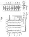
- FIG. 1 is a block diagram illustrating an entire configuration of a touch panel module (touch-panel device) employed in a first embodiment of the present invention.
- the touch panel module includes a touch panel 1, an electrostatic capacitance detecting unit 2, a control unit 3, a storage unit 4, and a bus connection signal line 5.
- electrodes X1 to X5 and electrodes Y1 to Y5 serving as sensor terminals for detecting a touch by a user are formed in an electrode pattern.
- the electrostatic capacitance detecting unit 2 is connected to the electrodes X1 to X5 and the electrodes Y1 to Y5, and measures electrostatic capacitance in each of the electrodes.
- the control unit 3 detects a touched position, based on the measured electrostatic capacitance, and notifies a host of the detection result via the bus connection signal line 5.
- the storage unit 4 stores the following values as parameters and working data necessary in a touched position detection process to be performed by the control unit 3.
- the parameters include a reference value 41, a measured value 42, and a difference value 43, which are sequence data with an element count corresponding to a total count of the electrodes. In the first embodiment, the element count of the sequence is 10.
- a touch threshold value 44, a conversion ratio 45, an overlap width X46, and an overlap width Y47 each are single numeric value data.
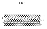
- FIG. 2 is a cross-sectional view illustrating a cross-sectional structure of the touch panel 1.
- an electrode layer Y, an insulating layer 12, an electrode layer X, and a protective layer 11 are laminated in the stated order on a substrate layer 13.
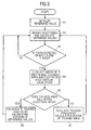
- FIG. 3 is a flow chart illustrating a procedure of the touched position detection process.
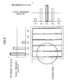
- FIG. 4 is a diagram illustrating examples of sensor measured values in a case where a touched area extends off an electrode area.
- FIG. 5 is a diagram illustrating how to calculate a touched position in a case where the touched area extends off the electrode area.
- Step S1 the control unit 3 initializes the reference value 41. Specifically, the control unit 3 measures electrostatic capacitance in each of all the electrodes (electrodes X1 to X5 and electrodes Y1 to Y5), and stores the value thus determined as the reference value 41 of each of the electrodes.
- the reference value 41 corresponds to electrostatic capacitance determined for each of the electrodes when the touch panel 1 is not touched. It is assumed here that the touch panel 1 is not touched when the touch panel module is turned on.
- the difference value 43 corresponds to electrostatic capacitance increased in each of the electrodes due to the touch on the touch panel 1.
- FIG. 4 a graph on the upper side of the touch panel 1 illustrates examples of the difference value 43 and the touch threshold value 44 determined for each of the electrodes X1 to X5.
- the electrodes X1 to X5 are plotted along the horizontal axis, and the height of the bar graph corresponds to the difference value 43.
- the difference values 43 of the electrodes X1 and X2 are equal to or larger than the touch threshold value 44, while the difference values 43 of the electrodes X3 to X5 are smaller than the touch threshold value 44.
- a graph on the right side of the touch panel 1 illustrates examples of the difference value 43 and the touch threshold value 44 determined for each of the electrodes Y1 to Y5.
- the electrodes Y1 to Y5 are plotted along the horizontal axis, and the height of the bar graph corresponds to the difference value 43.
- the difference values 43 of the electrodes Y2 to Y4 are equal to or larger than the touch threshold value 44, while the difference values 43 of the electrodes Y1 and Y5 are smaller than the touch threshold value 44.
- Step S3 the control unit 3 judges whether or not the touch panel 1 is touched. Specifically, the control unit 3 compares, for each of all the electrodes, the difference value 43 with the touch threshold value 44 set in advance. In this case, when both the X and Y axes include at least one electrode which has the difference value 43 equal to or larger than the touch threshold value 44, the control unit 3 judges that the touch panel 1 is touched, and proceeds to Step S4. When the above-mentioned condition is not satisfied, the control unit 3 judges that the touch panel 1 is not touched, and returns to Step S2. In the case illustrated in FIG. 4 , the difference values 43 of the electrodes X1 and X2 and the electrodes Y2 to Y4 are equal to or larger than the touch threshold value 44, and therefore it is judged that the touch panel 1 is touched.
- Step S4 the control unit 3 stores values determined by the expressions (2) and (3) below as the overlap width X46 and the overlap width Y47, respectively.
- Overlap width X ⁇ 46 MAX Difference value 43 of Y axis * Conversion ratio 45
- Overlap width Y ⁇ 47 MAX Difference value 43 of X axis * Conversion ratio 45
- the function MAX returns a largest value selected from a plurality of values.
- the difference value 43 of the electrode X1 is largest on the X axis while the difference value 43 of the electrode Y3 is largest on the Y axis.
- the conversion ratio 45 is a preset value, so as to convert the difference value 43 into a length on the touch panel 1.
- the overlap width X46 and the overlap width Y47 correspond to, as illustrated in FIG. 5 , the widths in the X direction and in the Y direction, respectively, of an area where an area touched (touched area) and an area where electrodes are arranged (electrode area 6) overlap each other on the touch panel 1.
- the reason why the overlap width X46 may be determined by the expression (2) is as follows. As is understood from FIG. 4 , the electrode Y3 overlaps the touched area with a largest width in the X direction, and hence a change in electrostatic capacitance is largest, with the result that the difference value 43 of the electrode Y3 becomes largest as illustrated in the graph on the right side.
- the electrodes Y2 and Y4 overlap the touched area with a width in the X direction smaller than that of the electrode Y3, and hence a change in electrostatic capacitance is smaller than that of the electrode Y3, with the result that the difference values 43 of the electrodes Y2 and Y4 are smaller than the difference value 43 of the electrode Y3 as illustrated in the graph on the right side.
- the electrodes Y1 and Y5 overlap the touched area with only a slight width in the X direction, and hence a change in electrostatic capacitance is very small, with the result that the difference values 43 of the electrodes Y1 and Y5 are very small as illustrated in the graph on the right side.
- the overlap width X46 corresponds to a width in the X direction of the area where the touched area and the electrode area 6 overlap each other, and hence the overlap width X46 is proportional to the width in the X direction with which the electrode Y3 overlaps the touched area, the electrode Y3 overlapping the touched area with a largest width in the X direction. Accordingly, the overlap width X46 is proportional to the difference value 43 of the electrode Y3. Therefore, the overlap width X46 may be determined by the expression (2).
- the conversion ratio 45 may be determined from experiment or the like.
- the reason why the overlap width Y47 may be determined by the expression (3) is as follows. As is understood from FIG. 4 , the electrode X1 overlaps the touched area with a largest width in the Y direction, and hence a change in electrostatic capacitance is largest, with the result that the difference value 43 of the electrode X1 becomes largest as illustrated in the graph on the upper side.
- the electrode X2 overlaps the touched area with a width in the Y direction smaller than that of the electrode X1, and hence a change in electrostatic capacitance is smaller than that of the electrode X1, with the result that the difference value 43 of the electrode X2 is smaller than the difference value 43 of the electrode X1 as illustrated in the graph on the upper side.
- the electrode X3 overlaps the touched area with only a slight width in the Y direction, and hence a change in electrostatic capacitance is very small, with the result that the difference value 43 of the electrode X3 is very small as illustrated in the graph on the upper side.
- the electrodes X4 and X5 do not overlap the touched area with a width in the Y direction, and hence no change in electrostatic capacitance is caused, with the result that the difference values 43 of the electrodes X4 and X5 are 0 as illustrated in the graph on the upper side.
- the overlap width Y47 corresponds to a width in the Y direction of the area where the touched area and the electrode area 6 overlap each other, and hence the overlap width Y47 is proportional to the width in the Y direction with which the electrode X1 overlaps the touched area, the electrode X1 overlapping the touched area with a largest width in the Y direction. Accordingly, the overlap width Y47 is proportional to the difference value 43 of the electrode X1. Therefore, the overlap width Y47 may be determined by the expression (3).
- the conversion ratio 45 may be determined from experiment or the like.
- Step S5 the control unit 3 compares the values of the overlap width X46 and the overlap width Y47 with each other. When the difference between the values is smaller than a predetermined threshold value, the control unit 3 judges that the entire touched area falls within the electrode area 6, and proceeds to Step S6. Otherwise, the control unit 3 proceeds to Step S7.
- Step S7 the control unit 3 assumes that the touched area is circular in shape, and calculates the center position of the circle as the touched position.
- the touched area extends off the electrode area 6 in the X direction.
- X and R correspond to the X coordinate and the overlap width Y47/2, respectively.
- the Y coordinate may be determined by the expression (5) which is adopted in the case where the touched area does not extend off the electrode area 6.
- X and Y may be replaced with each other in the calculation method described above, so as to determine the touched position similarly.
- the touched area is circular in shape.
- the first embodiment may be applied to any other case as long as the touched position may be calculated based on the overlap width X46 and the overlap width Y47. That is, a width in the X direction and a width in the Y direction of an area where the touched area and the electrode area overlap each other may be determined, and a position of the center of the touched area may be determined based on the width in the X direction and the width in the Y direction thus determined, to thereby calculate the position of the center thus determined as the touched position.
- the touched area may be assumed to be in an arbitrary shape. For example, the touched area may be assumed to be circular or oval in shape.
- the touched area may be assumed to be in a shape which has a constant ratio of a width thereof in the X direction to a width thereof in the Y direction (for example, in a square or rectangular shape, or in a square or rectangular shape having rounded corners). Still alternatively, the touched area may be in a shape determined from experiment or the like.
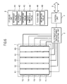
- FIG. 6 is a block diagram illustrating an entire configuration of a touch panel module according to the second embodiment.
- the storage unit 4 of the second embodiment stores a touch size 48 and a weighting value 49, in addition to the reference value 41, the measured value 42, the difference value 43, and the touch threshold value 44 described above.
- the touch size 48 is a single numerical data.
- the weighting value 49 is a single or a plurality of numerical data.
- FIG. 7 is a flow chart illustrating a procedure of a touched position detection process.
- FIG. 8 is a diagram illustrating a case where a touched position falls on a center of the touch panel.
- FIG. 9 is a diagram illustrating a case where a touched position falls on a periphery of the touch panel.
- Steps S11 to S13 The processing in Steps S11 to S13 is similarly performed as in Steps S1 to S3 of the first embodiment, and therefore the description thereof is omitted.
- Step S14 the control unit 3 determines a total of the difference values 43 of all the electrodes, that is, the electrodes X1 to X5 and the electrodes Y1 to Y5, and stores the determined value as the touch size 48.
- the touch size 48 assumes a value proportional to the size of the touched area, and is notified to the host as an index indicating a strength of the touch, together with the touched position to be detected in the following steps.
- the reason why the touch size (value proportional to the size of the touched area) is determined based on the total of the difference values 43 of all the electrodes is as follows. For example, in FIG.
- the difference value 43 of the electrode X1 is proportional to the size of the area where the electrode X1 and the touched area overlap each other
- the difference value 43 of the electrode X2 is proportional to the size of the area where the electrode X2 and the touched area overlap each other
- the difference value 43 of the electrode X3 is proportional to the size of the area where the electrode X3 and the touched area overlap each other
- the difference value 43 of the electrode X4 is proportional to the size of the area where the electrode X4 and the touched area overlap each other
- the difference value 43 of the electrode X5 is proportional to the size of the area where the electrode X5 and the touched area overlap each other.
- the difference values of all the electrodes may be summed, to thereby determine the touch size (value corresponding to the size of the touched area).
- the touch size is determined in the manner as described above.
- the touch size may be determined by any other method.
- a touched position in the Y direction may also be determined by a similar procedure.
- Step S15 the control unit 3 judges whether or not the detected touch falls on a periphery of the touch panel 1. Specifically, when any of the electrodes provided on the edge of the touch panel 1, that is, the electrode X1 or X5 has the difference value 43 which is largest, the control unit 3 judges that the touch falls on the periphery of the touch panel 1, and proceeds to Step S17. In a case where the above-mentioned condition is not satisfied, the control unit 3 judges that the touch does not fall on the periphery of the touch panel 1 (the touch falls on the center of the touch panel), and proceeds to Step S16. For example, in a state as illustrated in FIG.
- the electrode X2 which is not provided on the edge of the touch panel 1 has the difference value 43 which is largest, and hence it is judged that the touch does not fall on the periphery of the touch pane11.
- the electrode X1, which is provided on the edge of the touch panel 1 has the difference value 43 which is largest, and hence it is judged that the touch falls on the periphery of the touch panel 1.
- the electrode position xi corresponds to a coordinate value of the center of each of the electrodes.
- the electrodes X1 to X5 respectively have the electrode positions xi of 0.5, 1.5, 2.5, 3.5, and 4.5 in the stated order.
- one cycle of the touched position detection process is completed, and the control unit 3 returns to Step S12.
- Step S17 the control unit 3 determines, as a coordinate calculation process performed for a touch falling on the periphery of the touch panel 1, the touched position based on the largest difference value 43 of an electrode and the difference value 43 of another electrode next to the electrode (two electrodes provided on the edge of the touch panel 1). Specifically, the control unit 3 performs the calculation of the expression (7), as in Step S16, based on the two electrodes provided on the edge of the touch panel 1.
- the calculation performed in Step S17 is different from Step S16 in that the electrode positions xi, that is, parameter values of a sensor position, are defined as coordinate values of the outer edges of the two electrodes.
- the position of the electrode X1 is defined as 0, and the position of the electrode X2 is defined as 2.
- w1 w2
- the actual touched position is closer to the touched position of 0.57 calculated according to the second embodiment than to the touched position of 0.79 calculated based on the position coordinates of the centers of the electrodes.
- Step S15 it is judged that the touch falls on the periphery of the touch panel 1 under the condition that the difference value 43 of an electrode provided on the edge of the touch panel 1 is largest.
- another condition may also be employed.
- the judgment may be made under a condition that a total of the difference values 43 of an electrode provided on the edge of the touch panel 1 and of a predetermined number of electrodes adjacent to the electrode is larger than a total of the difference values 43 of the rest of the electrodes.
- Step S17 two electrodes provided on the edge of the touch panel 1 are referred to.
- the electrode positions xi are defined as outer edges of two electrodes when calculating a weighted average.
- the electrode positions xi may be defined differently. The number of electrodes to be referred to and the electrode position xi may be determined depending on the matters of design, such as an assumed size of the touched area or an assumed width of the electrodes.
- the touch-panel device has a feature in that the parameter values (x1 and x2 in the embodiment described above) for the sensor position to be used in the coordinate calculation process when the touch falls on the periphery of the touch panel 1 is different from those employed when the touch falls on the center of the touch panel 1.
- each of the electrodes which is referred to when calculating coordinates, is assigned a weight in order to reduce a deviation (error) of the calculated touched position from the actual touched position.
- weights may be various methods.
- there may be employed a method in which, in the expression (7), the difference value 43 (wi) of each of the electrodes may be multiplied by a predetermined weighting coefficient ai, which is expressed by the expression (9) below. Touched position ⁇ ai * wi * xi / ⁇ ai * wi
- Touched position 2 * a ⁇ 2 * w ⁇ 2 / a ⁇ 1 * w ⁇ 1 + a ⁇ 2 * w ⁇ 2
- the values of a1 and a2 are predetermined, and stored as the weighting value 49.
- the values of a1 and a2 may be determined from experiment or the like.
- the value a is predetermined, and stored as the weighting value 49.
- the value a (weighting value 49) may be determined from experiment or the like.
- each of the electrodes is assigned a weight based on a preset constant. However, an appropriate amount of the weight may not be fixed, and may vary depending on the strength of the touch.
- the values b and c are predetermined.
- the values b and c may be determined from experiment or the like.
- the left side of the touch panel 1 is illustrated by way of example. However, a touched position on the periphery on the right side, the upper side, or the lower side of the touch panel 1 may similarly be calculated with high accuracy.
- the touched position is detected by using both electrodes in the X direction and the Y direction, and hence the touched position may be detected with high accuracy in the periphery of the touch panel 1 in one of the X direction and Y direction, that is, the periphery of the touch panel 1 which does not include the corners of the touch panel 1.
- the touched position is detected by using the electrodes in only one direction (one of the X direction and the Y direction), and hence the touched position may be detected with high accuracy in the periphery of the touch panel 1 which includes the corners.
Landscapes
- Engineering & Computer Science (AREA)
- General Engineering & Computer Science (AREA)
- Theoretical Computer Science (AREA)
- Human Computer Interaction (AREA)
- Physics & Mathematics (AREA)
- General Physics & Mathematics (AREA)
- Position Input By Displaying (AREA)
Abstract
Description
- The present invention relates to a touch-panel device, and more particularly, to a technology of detecting a touched position in a projected capacitive type touch-panel device.
- A touch-panel device (also called touch screen) is a user interface device which includes an input device called touch pad and an output device formed of, for example, a flat panel display, in which the input device and the output device are integrally formed. The touch-panel device has a feature of an intuitive operation method in which an operation target displayed on a display is directly touched with a finger or the like, and is widely used for an information terminal device or the like.
- There are various methods of implementing the touch-panel device, and one of those methods includes a projected capacitive type system. According to the projected capacitive type system, a plurality of electrodes are arranged on the touch panel, and a touched position is detected based on a change in electrostatic capacitance of the electrodes caused when a fingertip approaches the touch panel. The electrodes are formed of a material with high transmittance and arranged on the display panel, to thereby form a touch-panel device.
- Accuracy of touched position detection may be referred to as a performance index of a touch panel as an input device. When an error between a position on the display panel actually touched by a user and a detected position is smaller, the accuracy is higher.
-
JP 2003-511799 A - Alternatively,
JP 2008-269297 A - However, the conventional touched position detecting method involves a problem that, in a case where a range (touched area) on the touch panel touched by a fingertip extends off an area (electrode area) where the electrodes are arranged, accuracy of touched position detection is reduced. In order to prevent such reduction in accuracy, an effective range for detecting a touched position needs to be limited to a certain range within the electrode area. Accordingly, even if the electrodes are arranged across the entire touch panel, a touched position falling on an area at the edge of the touch panel still may not be detected.
- The present invention has been made in order to solve the above-mentioned problems, and therefore, it is an object of the present invention to provide a touch-panel device capable of detecting a touched position with high accuracy even when a touched area extends off an electrode area, to thereby form the entire electrode area as an effective range for detecting the touched position.
- The invention proposes the subject matter of the independent claims for solving the above problems. In particular, the present invention provides two kinds of solving means as follows.
- According to first solving means, the touched area is assumed to be, for example, a circular in shape. A width in an X direction and a width in a Y direction of an area where the touched area in a circular shape and the electrode area overlap each other may be determined based on sensor measured values. When the width in the X direction and the width in the Y direction are different from each other, it is judged that the touched area extends off the electrode area, and a position of a center of the touched area in the circular shape is calculated as the touched position.
- According to second solving means, in a case where a signal value of an electrode provided on the edge of the touch panel becomes largest, it is judged whether or not a periphery of the touch panel is touched. In a case where the periphery of the touch panel is touched, a weighted average is calculated in the touched position calculation process based on an electrode position parameter value which is different from the value employed in a case where the center of the touch panel is touched. A signal value of each of the electrodes is assigned a weight and the weight is varied in accordance with a touch size, to thereby correct a calculated position.
- It should be noted that
JP 10-020992 A Patent Document 3, an electrode position adjacent to the electrode provided on the edge portion and an electrode position at another edge portion are selected, to thereby detect a touched position by using an approximate quadratic curve. Accordingly, this method is completely different from the method according to the present invention. - According to the first solving means, a touched position may be detected with high accuracy even in a case where the touched area extends off the electrode area in one of the X direction and the Y direction.
- According to the second solving means, a touched position may be detected with high accuracy by using an electrode for detecting a touched position in one direction, even in a case where the periphery of the touch panel is touched.
- In the accompanying drawings:
-
FIG. 1 is a block diagram illustrating an entire configuration of a touch panel module according to a first embodiment of the present invention; -
FIG. 2 is a cross-sectional view illustrating a cross-sectional structure of a touch panel; -
FIG. 3 is a flow chart illustrating a procedure of a touched position detection process; -
FIG. 4 is a diagram illustrating examples of sensor measured values in a case where a touched area extends off an electrode area; -
FIG. 5 is a diagram illustrating how to calculate a touched position in the case where the touched area extends off the electrode area; -
FIG. 6 is a block diagram illustrating an entire configuration of a touch panel module according to a second embodiment of the present invention; -
FIG. 7 is a flow chart illustrating another procedure of the touched position detection process; -
FIG. 8 is a diagram illustrating a case where a touched position falls on a center of the touch panel; and -
FIG. 9 is a diagram illustrating a case where a touched position falls on a periphery of the touch panel. - In the following, exemplary embodiments of the present invention are described.
-
FIG. 1 is a block diagram illustrating an entire configuration of a touch panel module (touch-panel device) employed in a first embodiment of the present invention. The touch panel module includes atouch panel 1, an electrostaticcapacitance detecting unit 2, acontrol unit 3, astorage unit 4, and a busconnection signal line 5. In thetouch panel 1, electrodes X1 to X5 and electrodes Y1 to Y5 serving as sensor terminals for detecting a touch by a user are formed in an electrode pattern. The electrostaticcapacitance detecting unit 2 is connected to the electrodes X1 to X5 and the electrodes Y1 to Y5, and measures electrostatic capacitance in each of the electrodes. Thecontrol unit 3 detects a touched position, based on the measured electrostatic capacitance, and notifies a host of the detection result via the busconnection signal line 5. Thestorage unit 4 stores the following values as parameters and working data necessary in a touched position detection process to be performed by thecontrol unit 3. The parameters include areference value 41, a measuredvalue 42, and adifference value 43, which are sequence data with an element count corresponding to a total count of the electrodes. In the first embodiment, the element count of the sequence is 10. Atouch threshold value 44, aconversion ratio 45, an overlap width X46, and an overlap width Y47 each are single numeric value data. -
FIG. 2 is a cross-sectional view illustrating a cross-sectional structure of thetouch panel 1. In thetouch panel 1, an electrode layer Y, aninsulating layer 12, an electrode layer X, and aprotective layer 11 are laminated in the stated order on asubstrate layer 13. -
FIG. 3 is a flow chart illustrating a procedure of the touched position detection process. -
FIG. 4 is a diagram illustrating examples of sensor measured values in a case where a touched area extends off an electrode area. -
FIG. 5 is a diagram illustrating how to calculate a touched position in a case where the touched area extends off the electrode area. - In the following, with reference to the flow chart of
FIG. 3 , a processing flow of detecting a touched position is described. - The following process is started when the touch panel module is turned on.
- In Step S1, the
control unit 3 initializes thereference value 41. Specifically, thecontrol unit 3 measures electrostatic capacitance in each of all the electrodes (electrodes X1 to X5 and electrodes Y1 to Y5), and stores the value thus determined as thereference value 41 of each of the electrodes. Thereference value 41 corresponds to electrostatic capacitance determined for each of the electrodes when thetouch panel 1 is not touched. It is assumed here that thetouch panel 1 is not touched when the touch panel module is turned on. - In Step S2, the
control unit 3 first measures electrostatic capacitance for each of all the electrodes, and stores the value thus determined as the measuredvalue 42 for each of the electrodes. Further, thecontrol unit 3 stores a value determined by the expression (1) below as thedifference value 43.
- It should be noted that in a case where a value determined by the expression (1) is negative, 0 is stored instead of the determined value, as the
difference value 43. Thedifference value 43 corresponds to electrostatic capacitance increased in each of the electrodes due to the touch on thetouch panel 1. - In the following, a description is given on the assumption that the difference values 43 are determined as illustrated in
FIG. 4 . InFIG. 4 , a graph on the upper side of thetouch panel 1 illustrates examples of thedifference value 43 and thetouch threshold value 44 determined for each of the electrodes X1 to X5. The electrodes X1 to X5 are plotted along the horizontal axis, and the height of the bar graph corresponds to thedifference value 43. The difference values 43 of the electrodes X1 and X2 are equal to or larger than thetouch threshold value 44, while the difference values 43 of the electrodes X3 to X5 are smaller than thetouch threshold value 44. InFIG. 4 , a graph on the right side of thetouch panel 1 illustrates examples of thedifference value 43 and thetouch threshold value 44 determined for each of the electrodes Y1 to Y5. The electrodes Y1 to Y5 are plotted along the horizontal axis, and the height of the bar graph corresponds to thedifference value 43. The difference values 43 of the electrodes Y2 to Y4 are equal to or larger than thetouch threshold value 44, while the difference values 43 of the electrodes Y1 and Y5 are smaller than thetouch threshold value 44. - In Step S3, the
control unit 3 judges whether or not thetouch panel 1 is touched. Specifically, thecontrol unit 3 compares, for each of all the electrodes, thedifference value 43 with thetouch threshold value 44 set in advance. In this case, when both the X and Y axes include at least one electrode which has thedifference value 43 equal to or larger than thetouch threshold value 44, thecontrol unit 3 judges that thetouch panel 1 is touched, and proceeds to Step S4. When the above-mentioned condition is not satisfied, thecontrol unit 3 judges that thetouch panel 1 is not touched, and returns to Step S2. In the case illustrated inFIG. 4 , the difference values 43 of the electrodes X1 and X2 and the electrodes Y2 to Y4 are equal to or larger than thetouch threshold value 44, and therefore it is judged that thetouch panel 1 is touched. - In Step S4, the
control unit 3 stores values determined by the expressions (2) and (3) below as the overlap width X46 and the overlap width Y47, respectively.

- Here, the function MAX returns a largest value selected from a plurality of values. In
FIG. 4 , thedifference value 43 of the electrode X1 is largest on the X axis while thedifference value 43 of the electrode Y3 is largest on the Y axis. Theconversion ratio 45 is a preset value, so as to convert thedifference value 43 into a length on thetouch panel 1. The overlap width X46 and the overlap width Y47 correspond to, as illustrated inFIG. 5 , the widths in the X direction and in the Y direction, respectively, of an area where an area touched (touched area) and an area where electrodes are arranged (electrode area 6) overlap each other on thetouch panel 1. - The reason why the overlap width X46 may be determined by the expression (2) is as follows. As is understood from
FIG. 4 , the electrode Y3 overlaps the touched area with a largest width in the X direction, and hence a change in electrostatic capacitance is largest, with the result that thedifference value 43 of the electrode Y3 becomes largest as illustrated in the graph on the right side. The electrodes Y2 and Y4 overlap the touched area with a width in the X direction smaller than that of the electrode Y3, and hence a change in electrostatic capacitance is smaller than that of the electrode Y3, with the result that the difference values 43 of the electrodes Y2 and Y4 are smaller than thedifference value 43 of the electrode Y3 as illustrated in the graph on the right side. The electrodes Y1 and Y5 overlap the touched area with only a slight width in the X direction, and hence a change in electrostatic capacitance is very small, with the result that the difference values 43 of the electrodes Y1 and Y5 are very small as illustrated in the graph on the right side. The overlap width X46 corresponds to a width in the X direction of the area where the touched area and theelectrode area 6 overlap each other, and hence the overlap width X46 is proportional to the width in the X direction with which the electrode Y3 overlaps the touched area, the electrode Y3 overlapping the touched area with a largest width in the X direction. Accordingly, the overlap width X46 is proportional to thedifference value 43 of the electrode Y3. Therefore, the overlap width X46 may be determined by the expression (2). Theconversion ratio 45 may be determined from experiment or the like. - The reason why the overlap width Y47 may be determined by the expression (3) is as follows. As is understood from
FIG. 4 , the electrode X1 overlaps the touched area with a largest width in the Y direction, and hence a change in electrostatic capacitance is largest, with the result that thedifference value 43 of the electrode X1 becomes largest as illustrated in the graph on the upper side. The electrode X2 overlaps the touched area with a width in the Y direction smaller than that of the electrode X1, and hence a change in electrostatic capacitance is smaller than that of the electrode X1, with the result that thedifference value 43 of the electrode X2 is smaller than thedifference value 43 of the electrode X1 as illustrated in the graph on the upper side. The electrode X3 overlaps the touched area with only a slight width in the Y direction, and hence a change in electrostatic capacitance is very small, with the result that thedifference value 43 of the electrode X3 is very small as illustrated in the graph on the upper side. The electrodes X4 and X5 do not overlap the touched area with a width in the Y direction, and hence no change in electrostatic capacitance is caused, with the result that the difference values 43 of the electrodes X4 and X5 are 0 as illustrated in the graph on the upper side. The overlap width Y47 corresponds to a width in the Y direction of the area where the touched area and theelectrode area 6 overlap each other, and hence the overlap width Y47 is proportional to the width in the Y direction with which the electrode X1 overlaps the touched area, the electrode X1 overlapping the touched area with a largest width in the Y direction. Accordingly, the overlap width Y47 is proportional to thedifference value 43 of the electrode X1. Therefore, the overlap width Y47 may be determined by the expression (3). Theconversion ratio 45 may be determined from experiment or the like. - In Step S5, the
control unit 3 compares the values of the overlap width X46 and the overlap width Y47 with each other. When the difference between the values is smaller than a predetermined threshold value, thecontrol unit 3 judges that the entire touched area falls within theelectrode area 6, and proceeds to Step S6. Otherwise, thecontrol unit 3 proceeds to Step S7. - In Step S6, the
control unit 3 determines a touched position based on thedifference value 43. Specifically, thecontrol unit 3 determines, for each of the X axis and the Y axis, a weighted average assuming that thedifference value 43 of each of the electrodes is a weight wi and the positions of the electrodes are xi and yi. In other words, thecontrol unit 3 performs calculations of the expressions (4) and (5) below.

- In the manner as described above, one cycle of the touched position detection process performed in the case where the touched area does not extend off the
electrode area 6 is completed, and thecontrol unit 3 returns to Step S2. - In Step S7, the
control unit 3 assumes that the touched area is circular in shape, and calculates the center position of the circle as the touched position. Here, as illustrated inFIG. 5 , it is assumed that the touched area extends off theelectrode area 6 in the X direction. In this case, the X coordinate of the touched position is determined by the expression (6) below.

- In
FIG. 5 , X and R correspond to the X coordinate and the overlap width Y47/2, respectively. The Y coordinate may be determined by the expression (5) which is adopted in the case where the touched area does not extend off theelectrode area 6. Alternatively, in a case where the touched area extends off theelectrode area 6 in the Y direction, X and Y may be replaced with each other in the calculation method described above, so as to determine the touched position similarly. - In the manner as described above, one cycle of the touched position detection process performed in the case where the touched area extends off the
electrode area 6 is completed, and thecontrol unit 3 returns to Step S2. - In the above description, it is assumed that the touched area is circular in shape. However, the first embodiment may be applied to any other case as long as the touched position may be calculated based on the overlap width X46 and the overlap width Y47. That is, a width in the X direction and a width in the Y direction of an area where the touched area and the electrode area overlap each other may be determined, and a position of the center of the touched area may be determined based on the width in the X direction and the width in the Y direction thus determined, to thereby calculate the position of the center thus determined as the touched position. The touched area may be assumed to be in an arbitrary shape. For example, the touched area may be assumed to be circular or oval in shape. Alternatively, the touched area may be assumed to be in a shape which has a constant ratio of a width thereof in the X direction to a width thereof in the Y direction (for example, in a square or rectangular shape, or in a square or rectangular shape having rounded corners). Still alternatively, the touched area may be in a shape determined from experiment or the like.
- Next, a second embodiment of the present invention is described. In the following, constituent elements that have been already described in the first embodiment are denoted by the same reference symbols, and the description thereof is omitted.
-
FIG. 6 is a block diagram illustrating an entire configuration of a touch panel module according to the second embodiment. Unlike thestorage unit 4 of the first embodiment, thestorage unit 4 of the second embodiment stores atouch size 48 and aweighting value 49, in addition to thereference value 41, the measuredvalue 42, thedifference value 43, and thetouch threshold value 44 described above. Thetouch size 48 is a single numerical data. Theweighting value 49 is a single or a plurality of numerical data. -
FIG. 7 is a flow chart illustrating a procedure of a touched position detection process. -
FIG. 8 is a diagram illustrating a case where a touched position falls on a center of the touch panel. -
FIG. 9 is a diagram illustrating a case where a touched position falls on a periphery of the touch panel. - In the following, with reference to the flow chart of
FIG. 7 , a processing flow of detecting a touched position is described. - The following process is started when the touch panel module is turned on.
- The processing in Steps S11 to S13 is similarly performed as in Steps S1 to S3 of the first embodiment, and therefore the description thereof is omitted.
- In Step S14, the
control unit 3 determines a total of the difference values 43 of all the electrodes, that is, the electrodes X1 to X5 and the electrodes Y1 to Y5, and stores the determined value as thetouch size 48. Thetouch size 48 assumes a value proportional to the size of the touched area, and is notified to the host as an index indicating a strength of the touch, together with the touched position to be detected in the following steps. The reason why the touch size (value proportional to the size of the touched area) is determined based on the total of the difference values 43 of all the electrodes is as follows. For example, inFIG. 8 , thedifference value 43 of the electrode X1 is proportional to the size of the area where the electrode X1 and the touched area overlap each other, thedifference value 43 of the electrode X2 is proportional to the size of the area where the electrode X2 and the touched area overlap each other, thedifference value 43 of the electrode X3 is proportional to the size of the area where the electrode X3 and the touched area overlap each other, thedifference value 43 of the electrode X4 is proportional to the size of the area where the electrode X4 and the touched area overlap each other, and thedifference value 43 of the electrode X5 is proportional to the size of the area where the electrode X5 and the touched area overlap each other. The same applies to the electrodes Y1 to Y5. Accordingly, the difference values of all the electrodes may be summed, to thereby determine the touch size (value corresponding to the size of the touched area). In the second embodiment, the touch size is determined in the manner as described above. However, the touch size may be determined by any other method. - In the following, a procedure of detecting a touched position in the X direction is described. A touched position in the Y direction may also be determined by a similar procedure.
- In Step S15, the
control unit 3 judges whether or not the detected touch falls on a periphery of thetouch panel 1. Specifically, when any of the electrodes provided on the edge of thetouch panel 1, that is, the electrode X1 or X5 has thedifference value 43 which is largest, thecontrol unit 3 judges that the touch falls on the periphery of thetouch panel 1, and proceeds to Step S17. In a case where the above-mentioned condition is not satisfied, thecontrol unit 3 judges that the touch does not fall on the periphery of the touch panel 1 (the touch falls on the center of the touch panel), and proceeds to Step S16. For example, in a state as illustrated inFIG. 8 , the electrode X2, which is not provided on the edge of thetouch panel 1, has thedifference value 43 which is largest, and hence it is judged that the touch does not fall on the periphery of the touch pane11. In a state as illustrated inFIG. 9 , the electrode X1, which is provided on the edge of thetouch panel 1, has thedifference value 43 which is largest, and hence it is judged that the touch falls on the periphery of thetouch panel 1. - In Step S16, the
control unit 3 determines, as a coordinate calculation process performed for a touch falling on the center of thetouch panel 1, the touched position based on thedifference value 43 of each of the electrodes. Specifically, thecontrol unit 3 determines a weighted average assuming that thedifference value 43 of each of the electrodes is a weight wi and the position of each of the electrodes is xi. In other words, thecontrol unit 3 performs a calculation of the expression (7) below.
- Here, the electrode position xi corresponds to a coordinate value of the center of each of the electrodes. In the state as illustrated in
FIG. 8 , the electrodes X1 to X5 respectively have the electrode positions xi of 0.5, 1.5, 2.5, 3.5, and 4.5 in the stated order. In the manner as described above, one cycle of the touched position detection process is completed, and thecontrol unit 3 returns to Step S12. - In Step S17, the
control unit 3 determines, as a coordinate calculation process performed for a touch falling on the periphery of thetouch panel 1, the touched position based on thelargest difference value 43 of an electrode and thedifference value 43 of another electrode next to the electrode (two electrodes provided on the edge of the touch panel 1). Specifically, thecontrol unit 3 performs the calculation of the expression (7), as in Step S16, based on the two electrodes provided on the edge of thetouch panel 1. The calculation performed in Step S17 is different from Step S16 in that the electrode positions xi, that is, parameter values of a sensor position, are defined as coordinate values of the outer edges of the two electrodes. In the state as illustrated inFIG. 9 , the position of the electrode X1 is defined as 0, and the position of the electrode X2 is defined as 2. The expression (8) below is calculated in this case, which is determined by substituting 0 and 2 into the electrode positions x1 and x2 for the two electrodes provided on the edge of thetouch panel 1 in the expression (7).
- In the expression (8), the coordinate values (x1=0 and x2=2) of the outer edges of two electrodes are selected as the electrode positions so that the touched position may be calculated as 0 (edge of the touch panel 1) when the
difference value 43 is measured only for the electrode X1 while the touched position may be calculated as 1 (midpoint between the electrode X1 and the electrode X2) when the difference values 43 of the electrode X1 and the electrode X2 are equal to each other, that is, w1=w2. For example, inFIG. 9 , when the difference value w1 of the electrode X1 is 1 and the difference value w2 of the electrode X2 is 0.4, the touched position is calculated as 0.57 by using the expression (8) when x1=0 and x2=2 according to the second embodiment. On the other hand, the touched position is calculated as 0.79 by using the expression (7) which is based on the position coordinates of the centers of two electrodes provided on the edge of the touch panel 1 (x1=0.5 and x2=1.5). As is apparent fromFIG. 9 , the actual touched position is closer to the touched position of 0.57 calculated according to the second embodiment than to the touched position of 0.79 calculated based on the position coordinates of the centers of the electrodes. - In the manner as described above, one cycle of the touched position detection process is completed, and the
control unit 3 returns to Step S12. - As described above, in Step S15, it is judged that the touch falls on the periphery of the
touch panel 1 under the condition that thedifference value 43 of an electrode provided on the edge of thetouch panel 1 is largest. However, another condition may also be employed. For example, the judgment may be made under a condition that a total of the difference values 43 of an electrode provided on the edge of thetouch panel 1 and of a predetermined number of electrodes adjacent to the electrode is larger than a total of the difference values 43 of the rest of the electrodes. - As described above, in Step S17, two electrodes provided on the edge of the
touch panel 1 are referred to. However, it is also conceivable to adopt a method in which three or more electrodes are referred to. Further, the electrode positions xi are defined as outer edges of two electrodes when calculating a weighted average. However, the electrode positions xi may be defined differently. The number of electrodes to be referred to and the electrode position xi may be determined depending on the matters of design, such as an assumed size of the touched area or an assumed width of the electrodes. - In the above, the second embodiment of the present invention has been specifically described. It should be noted that the touch-panel device according to the second embodiment has a feature in that the parameter values (x1 and x2 in the embodiment described above) for the sensor position to be used in the coordinate calculation process when the touch falls on the periphery of the
touch panel 1 is different from those employed when the touch falls on the center of thetouch panel 1. - Next, a third embodiment of the present invention is described. In the third embodiment, the expression for calculating coordinates in Step S17 of the second embodiment is modified.
- In the third embodiment, in the case where the touch falls on the periphery of the
touch panel 1, each of the electrodes, which is referred to when calculating coordinates, is assigned a weight in order to reduce a deviation (error) of the calculated touched position from the actual touched position. There may be various methods of assigning weights to the electrodes. As one example, there may be employed a method in which, in the expression (7), the difference value 43 (wi) of each of the electrodes may be multiplied by a predetermined weighting coefficient ai, which is expressed by the expression (9) below.
- In the expression (9), similarly to the second embodiment, the electrode positions xi of the two electrodes provided on the edge of the
touch panel 1 are defined by coordinate values of the outer edges of the two electrodes, that is, x1=0 and x2=2, which is expressed by the expression (10) below.
- The values of a1 and a2 are predetermined, and stored as the
weighting value 49. The values of a1 and a2 may be determined from experiment or the like. - As another example, there may be employed a method in which the difference value 43 (w2) of the electrode X2 is assigned a weight based on the expression (8) so as to calculate the expression (11) below.

- Here, the value a is predetermined, and stored as the
weighting value 49. The coefficient in the numerator is defined as 1+a so that the touched position may be calculated as 1 (midpoint between the electrodes X1 and X2) when the difference values 43 of the electrodes X1 and X2 are equal to each other, that is, w1=w2. The value a (weighting value 49) may be determined from experiment or the like. - Next, a fourth embodiment of the present invention is described. In the fourth embodiment, the third embodiment is modified.
- In the third embodiment, each of the electrodes is assigned a weight based on a preset constant. However, an appropriate amount of the weight may not be fixed, and may vary depending on the strength of the touch. In the fourth embodiment, a variable is employed as the weighting value, which is varied in accordance with the
touch size 48. There may be various methods to change the weighting value. For example, in the expression (11), theweighting value 49 may be changed in accordance with thetouch size 48. A predetermined function may be used to determine theweighting value 49. When the function is a linear function of thetouch size 48, the expression (12) below may be determined.
- Here, the values b and c are predetermined. The values b and c may be determined from experiment or the like.
- In the embodiments described above, the left side of the
touch panel 1 is illustrated by way of example. However, a touched position on the periphery on the right side, the upper side, or the lower side of thetouch panel 1 may similarly be calculated with high accuracy. - In the first embodiment, the touched position is detected by using both electrodes in the X direction and the Y direction, and hence the touched position may be detected with high accuracy in the periphery of the
touch panel 1 in one of the X direction and Y direction, that is, the periphery of thetouch panel 1 which does not include the corners of thetouch panel 1. On the other hand, in the second to fourth embodiments, the touched position is detected by using the electrodes in only one direction (one of the X direction and the Y direction), and hence the touched position may be detected with high accuracy in the periphery of thetouch panel 1 which includes the corners. - It should be noted that the present invention is not limited to the embodiments described above, and may be subjected to various modifications without departing from the gist of the present invention.
- While there have been described what are at present considered to be certain embodiments of the invention, it will be understood that various modifications may be made thereto, in particular by finding other combinations and sub-combinations of the features of the specification with the above described embodiments, claims and drawings. It is intended that the appended claims cover all such modifications falling within the true spirit and scope of the invention.
Claims (9)
- A touch-panel device for detecting a touched position based on sensor measured values determined by a plurality of sensors, the touch-panel device being configured to:determine, based on the sensor measured values for detecting a touched position in an X direction and a touched position in a Y direction, a width (46) in the X direction and a width (47) in the Y direction of an area where a touched area and an electrode area (6) overlap each other;determine, based on the width (46) in the X direction and the width (47) in the Y direction, a position of a center of the touched area; andcalculate the position of the center as the touched position.
- The touch-panel device according to claim 1, wherein the touched area is assumed to be in a shape which has a constant ratio of a width thereof in the X direction to a width thereof in the Y direction.
- The touch-panel device according to claim 1 or 2, wherein the touched area is assumed to be one of circular and oval in shape.
- The touch-panel device according to one of the preceding claims, wherein:the width (46) in the X direction of the area where the touched area and the electrode area (6) overlap each other is determined by multiplying a largest value of the sensor measured values on a Y axis by a preset value; andthe width (47) in the Y direction of the area where the touched area and the electrode area (6) overlap each other is determined by multiplying a largest value of the sensor measured values on an X axis by a preset value.
- The touch-panel device according to one of the preceding claims, wherein a touched position in a first direction is determined by subtracting, from a width in the first direction of the area where the touched area and the electrode area (6) overlap each other, a one-second of a width in a second direction of the area where the touched area and the electrode area (6) overlap each other.
- A touch-panel device for detecting a touched position based on sensor measured values determined by a plurality of sensors and on positions of the plurality of sensors,
the touch-panel device being conf igured to perform a coordinate calculation process by using parameter values for the positions of the plurality of sensors, the parameter values employed in a case where a periphery of a touch panel is touched being different from parameter values employed when a center of the touch panel is touched. - The touch-panel device according to claim 6, wherein the parameter values for the positions of the plurality of sensors employed in the coordinate calculation process in the case where the periphery of the touch panel is touched are defined by coordinate values of both outer edges of two electrodes provided at an edge of the touch panel.
- The touch-panel device according to claim 6 or 7, wherein, in the coordinate calculation process performed in the case where the periphery of the touch panel is touched, the sensor measured values to be referred to are each assigned a predetermined weight.
- The touch-panel device according to claim 8, wherein the predetermined weight is varied in accordance with a touch size.
Applications Claiming Priority (2)
| Application Number | Priority Date | Filing Date | Title |
|---|---|---|---|
| JP2009098235A JP5219908B2 (en) | 2009-04-14 | 2009-04-14 | Touch panel device |
| JP2009196958A JP5219965B2 (en) | 2009-08-27 | 2009-08-27 | Touch panel device |
Publications (3)
| Publication Number | Publication Date |
|---|---|
| EP2241959A2 true EP2241959A2 (en) | 2010-10-20 |
| EP2241959A3 EP2241959A3 (en) | 2013-11-06 |
| EP2241959B1 EP2241959B1 (en) | 2018-10-31 |
Family
ID=42269415
Family Applications (1)
| Application Number | Title | Priority Date | Filing Date |
|---|---|---|---|
| EP10003950.2A Active EP2241959B1 (en) | 2009-04-14 | 2010-04-14 | Touch-panel device |
Country Status (4)
| Country | Link |
|---|---|
| US (1) | US9024886B2 (en) |
| EP (1) | EP2241959B1 (en) |
| KR (1) | KR101138622B1 (en) |
| CN (1) | CN101866239B (en) |
Cited By (1)
| Publication number | Priority date | Publication date | Assignee | Title |
|---|---|---|---|---|
| WO2015126759A1 (en) * | 2014-02-21 | 2015-08-27 | Qualcomm Incorporated | Systems and methods for improved touch screen accuracy |
Families Citing this family (41)
| Publication number | Priority date | Publication date | Assignee | Title |
|---|---|---|---|---|
| US8902174B1 (en) | 2008-02-29 | 2014-12-02 | Cypress Semiconductor Corporation | Resolving multiple presences over a touch sensor array |
| US8810543B1 (en) | 2010-05-14 | 2014-08-19 | Cypress Semiconductor Corporation | All points addressable touch sensing surface |
| US8797281B2 (en) * | 2010-06-16 | 2014-08-05 | Atmel Corporation | Touch-screen panel with multiple sense units and related methods |
| US8692795B1 (en) * | 2010-08-24 | 2014-04-08 | Cypress Semiconductor Corporation | Contact identification and tracking on a capacitance sensing array |
| JP5382815B2 (en) * | 2010-10-28 | 2014-01-08 | シャープ株式会社 | Remote control and remote control program |
| US8531418B2 (en) | 2010-11-22 | 2013-09-10 | Integrated Device Technology Inc | Touch sensor having improved edge response |
| US8884916B2 (en) | 2010-12-09 | 2014-11-11 | Synaptics Incorporated | System and method for determining user input using polygons |
| JP5812015B2 (en) * | 2011-02-16 | 2015-11-11 | 日本電気株式会社 | Input device, input method, and program |
| JP5659073B2 (en) * | 2011-04-22 | 2015-01-28 | 株式会社ジャパンディスプレイ | Display panel with touch detector and electronic device |
| US20120306802A1 (en) * | 2011-06-06 | 2012-12-06 | Mccracken David Harold | Differential capacitance touch sensor |
| US8674956B2 (en) * | 2011-06-13 | 2014-03-18 | Chimei Innolux Corporation | In-cell touch sensor touch area enhancing algorithm |
| JP5738707B2 (en) * | 2011-07-28 | 2015-06-24 | 株式会社ジャパンディスプレイ | Touch panel |
| US20130093719A1 (en) * | 2011-10-17 | 2013-04-18 | Sony Mobile Communications Japan, Inc. | Information processing apparatus |
| US8674962B2 (en) * | 2011-11-30 | 2014-03-18 | Silicon Integrated Systems Corp. | Touch coordinate calculation method for touch panel |
| CN103164065A (en) * | 2011-12-16 | 2013-06-19 | 迅杰科技股份有限公司 | Point reporting device and point reporting method |
| KR101991493B1 (en) | 2012-01-17 | 2019-06-20 | 삼성전자주식회사 | Method for providing touch interface, machine-readable storage medium and portable terminal |
| US20130207913A1 (en) * | 2012-02-09 | 2013-08-15 | Sony Mobile Communications Inc. | Touch panel device, portable terminal, position detecting method, and recording medium |
| WO2014018121A1 (en) | 2012-07-26 | 2014-01-30 | Changello Enterprise Llc | Fingerprint-assisted force estimation |
| WO2014018116A1 (en) | 2012-07-26 | 2014-01-30 | Changello Enterprise Llc | Ultrasound-based force sensing and touch sensing |
| WO2014018115A1 (en) | 2012-07-26 | 2014-01-30 | Changello Enterprise Llc | Ultrasound-based force sensing of inputs |
| US9563304B2 (en) * | 2012-08-15 | 2017-02-07 | Atmel Corporation | Active stylus with passive mutual measurements |
| WO2014035479A2 (en) | 2012-08-30 | 2014-03-06 | Changello Enterprise Llc | Auto-baseline determination for force sensing |
| US9772722B2 (en) * | 2012-10-22 | 2017-09-26 | Parade Technologies, Ltd. | Position sensing methods and devices with dynamic gain for edge positioning |
| KR101984092B1 (en) * | 2012-10-24 | 2019-09-03 | 엘지전자 주식회사 | Mobile terminal and touch quality deterioration compensating method thereof |
| KR101984095B1 (en) * | 2012-11-26 | 2019-05-30 | 엘지전자 주식회사 | Mobile terminal and control method thereof |
| TWI486858B (en) | 2012-12-28 | 2015-06-01 | Egalax Empia Technology Inc | Method and device for position detection |
| TWI506515B (en) * | 2013-02-04 | 2015-11-01 | Novatek Microelectronics Corp | Coordinate calculating method and touch control module for single layer capacitance sensing device |
| JP5679595B2 (en) * | 2013-03-14 | 2015-03-04 | パナソニック インテレクチュアル プロパティ コーポレーション オブアメリカPanasonic Intellectual Property Corporation of America | Electronic device and coordinate determination method |
| US10078365B2 (en) * | 2013-04-19 | 2018-09-18 | Lg Electronics Inc. | Device for controlling mobile terminal and method of controlling the mobile terminal |
| CN104777948B (en) * | 2014-01-13 | 2018-04-17 | 上海和辉光电有限公司 | Improve the method and device of Projected capacitive touch panel edge coordinate accuracy |
| JP6303575B2 (en) * | 2014-02-18 | 2018-04-04 | 日本電産リード株式会社 | Touch panel touch position detection method, touch panel inspection method, and touch panel inspection apparatus |
| CN104978090B (en) * | 2014-04-11 | 2018-03-23 | 中国电信股份有限公司 | According to the method and system at user behavior amendment touch-screen touch-control center |
| CN105117049B (en) * | 2014-05-07 | 2019-09-03 | 禾瑞亚科技股份有限公司 | Touch information transmission method, processor and system |
| KR20160102698A (en) * | 2015-02-23 | 2016-08-31 | 이래오토모티브시스템 주식회사 | Touch panel testing method and apparatus |
| US9804717B2 (en) | 2015-03-11 | 2017-10-31 | Synaptics Incorporated | Input sensing and exclusion |
| JP6858646B2 (en) * | 2017-05-29 | 2021-04-14 | エルジー ディスプレイ カンパニー リミテッド | Touch detection device and touch detection method |
| CN108874234B (en) * | 2018-08-02 | 2022-03-04 | 深圳市德明利技术股份有限公司 | A touch recognition method, device and touch display device |
| CN109908580B (en) * | 2019-01-25 | 2022-11-29 | 深圳优依购互娱科技有限公司 | Game interface optimization method, computer device and storage medium |
| WO2021070313A1 (en) * | 2019-10-10 | 2021-04-15 | 株式会社ワコム | Touch detection method and touch detection device |
| KR102703334B1 (en) | 2019-12-18 | 2024-09-06 | 주식회사 엘엑스세미콘 | Device and Method for Sensing Touch |
| KR102186184B1 (en) * | 2020-02-28 | 2020-12-03 | 주식회사 에이코닉 | Touch sensor and driving method thereof |
Citations (3)
| Publication number | Priority date | Publication date | Assignee | Title |
|---|---|---|---|---|
| JPH1020992A (en) | 1996-07-05 | 1998-01-23 | Alps Electric Co Ltd | Coordinate input device |
| JP2003511799A (en) | 1999-10-08 | 2003-03-25 | シナプティクス インコーポレイテッド | Flexible and transparent contact detection system for electronic devices |
| JP2008269297A (en) | 2007-04-20 | 2008-11-06 | Seiko Epson Corp | Coordinate input device and display device |
Family Cites Families (37)
| Publication number | Priority date | Publication date | Assignee | Title |
|---|---|---|---|---|
| US7911456B2 (en) | 1992-06-08 | 2011-03-22 | Synaptics Incorporated | Object position detector with edge motion feature and gesture recognition |
| US5880411A (en) * | 1992-06-08 | 1999-03-09 | Synaptics, Incorporated | Object position detector with edge motion feature and gesture recognition |
| JPH07230352A (en) | 1993-09-16 | 1995-08-29 | Hitachi Ltd | Touch position detection device and touch instruction processing device |
| US5510805A (en) * | 1994-08-08 | 1996-04-23 | Prime View International Co. | Scanning circuit |
| US5825352A (en) * | 1996-01-04 | 1998-10-20 | Logitech, Inc. | Multiple fingers contact sensing method for emulating mouse buttons and mouse operations on a touch sensor pad |
| KR100260760B1 (en) * | 1996-07-31 | 2000-07-01 | 모리 하루오 | Information display device with a touch panel |
| US7844914B2 (en) * | 2004-07-30 | 2010-11-30 | Apple Inc. | Activating virtual keys of a touch-screen virtual keyboard |
| US7663607B2 (en) * | 2004-05-06 | 2010-02-16 | Apple Inc. | Multipoint touchscreen |
| IL137478A (en) * | 1998-01-26 | 2005-11-20 | Westerman Wayne | Method and apparatus for integrating manual input |
| US6211856B1 (en) * | 1998-04-17 | 2001-04-03 | Sung M. Choi | Graphical user interface touch screen with an auto zoom feature |
| US6411283B1 (en) * | 1999-05-20 | 2002-06-25 | Micron Technology, Inc. | Computer touch screen adapted to facilitate selection of features at edge of screen |
| US6727892B1 (en) * | 1999-05-20 | 2004-04-27 | Micron Technology, Inc. | Method of facilitating the selection of features at edges of computer touch screens |
| JP2003337659A (en) * | 2002-05-20 | 2003-11-28 | Sharp Corp | Input device and touch area registration method |
| US7489306B2 (en) * | 2004-12-22 | 2009-02-10 | Microsoft Corporation | Touch screen accuracy |
| JP4551830B2 (en) * | 2005-07-08 | 2010-09-29 | 任天堂株式会社 | Pointing device input adjustment program and input adjustment device |
| US8121283B2 (en) * | 2006-05-18 | 2012-02-21 | Cypress Semiconductor Corporation | Tapered capacitive sensing structure |
| US8243027B2 (en) * | 2006-06-09 | 2012-08-14 | Apple Inc. | Touch screen liquid crystal display |
| US8059102B2 (en) * | 2006-06-13 | 2011-11-15 | N-Trig Ltd. | Fingertip touch recognition for a digitizer |
| US8686964B2 (en) * | 2006-07-13 | 2014-04-01 | N-Trig Ltd. | User specific recognition of intended user interaction with a digitizer |
| US7843427B2 (en) * | 2006-09-06 | 2010-11-30 | Apple Inc. | Methods for determining a cursor position from a finger contact with a touch screen display |
| US7924271B2 (en) * | 2007-01-05 | 2011-04-12 | Apple Inc. | Detecting gestures on multi-event sensitive devices |
| DE102007023290A1 (en) * | 2007-05-16 | 2008-11-20 | Volkswagen Ag | Multifunction display and control device and method for operating a multifunction display and control device with improved selection operation |
| US7916126B2 (en) * | 2007-06-13 | 2011-03-29 | Apple Inc. | Bottom-up watershed dataflow method and region-specific segmentation based on historic data to identify patches on a touch sensor panel |
| US7990368B2 (en) * | 2007-12-26 | 2011-08-02 | Elan Microelectronics Corp. | Method for calibrating coordinates of touch screen |
| US20090174679A1 (en) * | 2008-01-04 | 2009-07-09 | Wayne Carl Westerman | Selective Rejection of Touch Contacts in an Edge Region of a Touch Surface |
| US20100079413A1 (en) * | 2008-09-29 | 2010-04-01 | Denso Corporation | Control device |
| US8284170B2 (en) * | 2008-09-30 | 2012-10-09 | Apple Inc. | Touch screen device, method, and graphical user interface for moving on-screen objects without using a cursor |
| US20100097329A1 (en) * | 2008-10-21 | 2010-04-22 | Martin Simmons | Touch Position Finding Method and Apparatus |
| US20100107067A1 (en) * | 2008-10-27 | 2010-04-29 | Nokia Corporation | Input on touch based user interfaces |
| CN101387927B (en) | 2008-11-04 | 2010-09-08 | 友达光电股份有限公司 | Touch detection method for touch panel |
| US8279184B2 (en) * | 2009-01-27 | 2012-10-02 | Research In Motion Limited | Electronic device including a touchscreen and method |
| US8154529B2 (en) * | 2009-05-14 | 2012-04-10 | Atmel Corporation | Two-dimensional touch sensors |
| US8723827B2 (en) * | 2009-07-28 | 2014-05-13 | Cypress Semiconductor Corporation | Predictive touch surface scanning |
| US8477106B2 (en) * | 2009-07-29 | 2013-07-02 | Elo Touch Solutions, Inc. | System and method for a projected capacitive touchscreen having weight based coordinate determination |
| US8334849B2 (en) * | 2009-08-25 | 2012-12-18 | Pixart Imaging Inc. | Firmware methods and devices for a mutual capacitance touch sensing device |
| JP5418187B2 (en) * | 2009-12-02 | 2014-02-19 | ソニー株式会社 | Contact operation determination device, contact operation determination method, and program |
| US8674956B2 (en) * | 2011-06-13 | 2014-03-18 | Chimei Innolux Corporation | In-cell touch sensor touch area enhancing algorithm |
-
2010
- 2010-04-13 US US12/759,045 patent/US9024886B2/en active Active
- 2010-04-13 KR KR20100033846A patent/KR101138622B1/en not_active Expired - Fee Related
- 2010-04-14 CN CN2010101642515A patent/CN101866239B/en active Active
- 2010-04-14 EP EP10003950.2A patent/EP2241959B1/en active Active
Patent Citations (3)
| Publication number | Priority date | Publication date | Assignee | Title |
|---|---|---|---|---|
| JPH1020992A (en) | 1996-07-05 | 1998-01-23 | Alps Electric Co Ltd | Coordinate input device |
| JP2003511799A (en) | 1999-10-08 | 2003-03-25 | シナプティクス インコーポレイテッド | Flexible and transparent contact detection system for electronic devices |
| JP2008269297A (en) | 2007-04-20 | 2008-11-06 | Seiko Epson Corp | Coordinate input device and display device |
Cited By (1)
| Publication number | Priority date | Publication date | Assignee | Title |
|---|---|---|---|---|
| WO2015126759A1 (en) * | 2014-02-21 | 2015-08-27 | Qualcomm Incorporated | Systems and methods for improved touch screen accuracy |
Also Published As
| Publication number | Publication date |
|---|---|
| EP2241959A3 (en) | 2013-11-06 |
| EP2241959B1 (en) | 2018-10-31 |
| KR20100113989A (en) | 2010-10-22 |
| US20100259504A1 (en) | 2010-10-14 |
| KR101138622B1 (en) | 2012-05-16 |
| CN101866239B (en) | 2013-12-11 |
| US9024886B2 (en) | 2015-05-05 |
| CN101866239A (en) | 2010-10-20 |
Similar Documents
| Publication | Publication Date | Title |
|---|---|---|
| EP2241959B1 (en) | Touch-panel device | |
| JP5219965B2 (en) | Touch panel device | |
| EP4216043B1 (en) | Open close detection of foldable phone lid angle calculation | |
| US8847914B2 (en) | Touched position detection method for touch panel | |
| US9557849B2 (en) | Touch panel and input recognition device using the touch panel | |
| US8350826B2 (en) | Capacitive touch panel device | |
| JP5740411B2 (en) | Method for scanning projected capacitive touch panel, storage medium and apparatus for scanning projected capacitive touch panel | |
| EP2638458B1 (en) | Touch device for determining real coordinates of multiple touch points and method thereof | |
| US20140354585A1 (en) | Capacitive touch screen with force detection | |
| US9983738B2 (en) | Contact detection mode switching in a touchscreen device | |
| US20180307365A1 (en) | Coordinate detection device and operating method thereof | |
| CN110036362B (en) | Touch detection method and touch detection device | |
| US8514193B2 (en) | Touch sensing method and touch sensing system | |
| US10613695B2 (en) | Integrated touch sensing and force sensing in a touch detection device | |
| EP3108340A1 (en) | Systems and methods for improved touch screen accuracy | |
| CN101950228B (en) | Touch point detection method | |
| JP2014525610A (en) | High resolution ghost removal gesture | |
| US9733772B2 (en) | Correction apparatus and correction method for self-capacitive touch panel | |
| EP4204936B1 (en) | Displacement sensing apparatus | |
| CN108604146B (en) | Touch device and method for determining capacitance sensing amount of touch device | |
| JP5219908B2 (en) | Touch panel device | |
| US9495054B2 (en) | Touch control system and coordinate correction method thereof | |
| CN102314249A (en) | Touch sensing method and touch sensing system | |
| US11977706B2 (en) | Touch panel device | |
| CN118363497A (en) | Coordinate input device |
Legal Events
| Date | Code | Title | Description |
|---|---|---|---|
| PUAI | Public reference made under article 153(3) epc to a published international application that has entered the european phase |
Free format text: ORIGINAL CODE: 0009012 |
|
| 17P | Request for examination filed |
Effective date: 20100414 |
|
| AK | Designated contracting states |
Kind code of ref document: A2 Designated state(s): AT BE BG CH CY CZ DE DK EE ES FI FR GB GR HR HU IE IS IT LI LT LU LV MC MK MT NL NO PL PT RO SE SI SK SM TR |
|
| AX | Request for extension of the european patent |
Extension state: AL BA ME RS |
|
| RAP1 | Party data changed (applicant data changed or rights of an application transferred) |
Owner name: PANASONIC LIQUID CRYSTAL DISPLAY CO., LTD. Owner name: HITACHI DISPLAYS, LTD. |
|
| RIC1 | Information provided on ipc code assigned before grant |
Ipc: G06F 3/041 20060101ALI20130702BHEP Ipc: G06F 3/044 20060101AFI20130702BHEP |
|
| PUAL | Search report despatched |
Free format text: ORIGINAL CODE: 0009013 |
|
| AK | Designated contracting states |
Kind code of ref document: A3 Designated state(s): AT BE BG CH CY CZ DE DK EE ES FI FR GB GR HR HU IE IS IT LI LT LU LV MC MK MT NL NO PL PT RO SE SI SK SM TR |
|
| AX | Request for extension of the european patent |
Extension state: AL BA ME RS |
|
| RIC1 | Information provided on ipc code assigned before grant |
Ipc: G06F 3/044 20060101AFI20131002BHEP Ipc: G06F 3/041 20060101ALI20131002BHEP |
|
| RBV | Designated contracting states (corrected) |
Designated state(s): AT BE BG CH CY CZ DE DK EE ES FI FR GB GR HR HU IE IS IT LI LT LU LV MC MK MT NL NO PL PT RO SE SI SK SM TR |
|
| STAA | Information on the status of an ep patent application or granted ep patent |
Free format text: STATUS: EXAMINATION IS IN PROGRESS |
|
| 17Q | First examination report despatched |
Effective date: 20180306 |
|
| RAP1 | Party data changed (applicant data changed or rights of an application transferred) |
Owner name: PANASONIC LIQUID CRYSTAL DISPLAY CO., LTD. Owner name: JAPAN DISPLAY INC. |
|
| GRAP | Despatch of communication of intention to grant a patent |
Free format text: ORIGINAL CODE: EPIDOSNIGR1 |
|
| STAA | Information on the status of an ep patent application or granted ep patent |
Free format text: STATUS: GRANT OF PATENT IS INTENDED |
|
| INTG | Intention to grant announced |
Effective date: 20180615 |
|
| GRAS | Grant fee paid |
Free format text: ORIGINAL CODE: EPIDOSNIGR3 |
|
| GRAA | (expected) grant |
Free format text: ORIGINAL CODE: 0009210 |
|
| STAA | Information on the status of an ep patent application or granted ep patent |
Free format text: STATUS: THE PATENT HAS BEEN GRANTED |
|
| AK | Designated contracting states |
Kind code of ref document: B1 Designated state(s): AT BE BG CH CY CZ DE DK EE ES FI FR GB GR HR HU IE IS IT LI LT LU LV MC MK MT NL NO PL PT RO SE SI SK SM TR |
|
| REG | Reference to a national code |
Ref country code: CH Ref legal event code: EP Ref country code: GB Ref legal event code: FG4D |
|
| REG | Reference to a national code |
Ref country code: AT Ref legal event code: REF Ref document number: 1060182 Country of ref document: AT Kind code of ref document: T Effective date: 20181115 |
|
| REG | Reference to a national code |
Ref country code: DE Ref legal event code: R096 Ref document number: 602010054697 Country of ref document: DE |
|
| REG | Reference to a national code |
Ref country code: IE Ref legal event code: FG4D |
|
| REG | Reference to a national code |
Ref country code: NL Ref legal event code: MP Effective date: 20181031 |
|
| REG | Reference to a national code |
Ref country code: LT Ref legal event code: MG4D |
|
| REG | Reference to a national code |
Ref country code: AT Ref legal event code: MK05 Ref document number: 1060182 Country of ref document: AT Kind code of ref document: T Effective date: 20181031 |
|
| PG25 | Lapsed in a contracting state [announced via postgrant information from national office to epo] |
Ref country code: AT Free format text: LAPSE BECAUSE OF FAILURE TO SUBMIT A TRANSLATION OF THE DESCRIPTION OR TO PAY THE FEE WITHIN THE PRESCRIBED TIME-LIMIT Effective date: 20181031 Ref country code: LV Free format text: LAPSE BECAUSE OF FAILURE TO SUBMIT A TRANSLATION OF THE DESCRIPTION OR TO PAY THE FEE WITHIN THE PRESCRIBED TIME-LIMIT Effective date: 20181031 Ref country code: PL Free format text: LAPSE BECAUSE OF FAILURE TO SUBMIT A TRANSLATION OF THE DESCRIPTION OR TO PAY THE FEE WITHIN THE PRESCRIBED TIME-LIMIT Effective date: 20181031 Ref country code: HR Free format text: LAPSE BECAUSE OF FAILURE TO SUBMIT A TRANSLATION OF THE DESCRIPTION OR TO PAY THE FEE WITHIN THE PRESCRIBED TIME-LIMIT Effective date: 20181031 Ref country code: IS Free format text: LAPSE BECAUSE OF FAILURE TO SUBMIT A TRANSLATION OF THE DESCRIPTION OR TO PAY THE FEE WITHIN THE PRESCRIBED TIME-LIMIT Effective date: 20190228 Ref country code: NO Free format text: LAPSE BECAUSE OF FAILURE TO SUBMIT A TRANSLATION OF THE DESCRIPTION OR TO PAY THE FEE WITHIN THE PRESCRIBED TIME-LIMIT Effective date: 20190131 Ref country code: BG Free format text: LAPSE BECAUSE OF FAILURE TO SUBMIT A TRANSLATION OF THE DESCRIPTION OR TO PAY THE FEE WITHIN THE PRESCRIBED TIME-LIMIT Effective date: 20190131 Ref country code: LT Free format text: LAPSE BECAUSE OF FAILURE TO SUBMIT A TRANSLATION OF THE DESCRIPTION OR TO PAY THE FEE WITHIN THE PRESCRIBED TIME-LIMIT Effective date: 20181031 Ref country code: ES Free format text: LAPSE BECAUSE OF FAILURE TO SUBMIT A TRANSLATION OF THE DESCRIPTION OR TO PAY THE FEE WITHIN THE PRESCRIBED TIME-LIMIT Effective date: 20181031 Ref country code: FI Free format text: LAPSE BECAUSE OF FAILURE TO SUBMIT A TRANSLATION OF THE DESCRIPTION OR TO PAY THE FEE WITHIN THE PRESCRIBED TIME-LIMIT Effective date: 20181031 |
|
| PG25 | Lapsed in a contracting state [announced via postgrant information from national office to epo] |
Ref country code: PT Free format text: LAPSE BECAUSE OF FAILURE TO SUBMIT A TRANSLATION OF THE DESCRIPTION OR TO PAY THE FEE WITHIN THE PRESCRIBED TIME-LIMIT Effective date: 20190301 Ref country code: SE Free format text: LAPSE BECAUSE OF FAILURE TO SUBMIT A TRANSLATION OF THE DESCRIPTION OR TO PAY THE FEE WITHIN THE PRESCRIBED TIME-LIMIT Effective date: 20181031 Ref country code: GR Free format text: LAPSE BECAUSE OF FAILURE TO SUBMIT A TRANSLATION OF THE DESCRIPTION OR TO PAY THE FEE WITHIN THE PRESCRIBED TIME-LIMIT Effective date: 20190201 Ref country code: NL Free format text: LAPSE BECAUSE OF FAILURE TO SUBMIT A TRANSLATION OF THE DESCRIPTION OR TO PAY THE FEE WITHIN THE PRESCRIBED TIME-LIMIT Effective date: 20181031 |
|
| PG25 | Lapsed in a contracting state [announced via postgrant information from national office to epo] |
Ref country code: DK Free format text: LAPSE BECAUSE OF FAILURE TO SUBMIT A TRANSLATION OF THE DESCRIPTION OR TO PAY THE FEE WITHIN THE PRESCRIBED TIME-LIMIT Effective date: 20181031 Ref country code: CZ Free format text: LAPSE BECAUSE OF FAILURE TO SUBMIT A TRANSLATION OF THE DESCRIPTION OR TO PAY THE FEE WITHIN THE PRESCRIBED TIME-LIMIT Effective date: 20181031 Ref country code: IT Free format text: LAPSE BECAUSE OF FAILURE TO SUBMIT A TRANSLATION OF THE DESCRIPTION OR TO PAY THE FEE WITHIN THE PRESCRIBED TIME-LIMIT Effective date: 20181031 |
|
| REG | Reference to a national code |
Ref country code: DE Ref legal event code: R097 Ref document number: 602010054697 Country of ref document: DE |
|
| PG25 | Lapsed in a contracting state [announced via postgrant information from national office to epo] |
Ref country code: RO Free format text: LAPSE BECAUSE OF FAILURE TO SUBMIT A TRANSLATION OF THE DESCRIPTION OR TO PAY THE FEE WITHIN THE PRESCRIBED TIME-LIMIT Effective date: 20181031 Ref country code: EE Free format text: LAPSE BECAUSE OF FAILURE TO SUBMIT A TRANSLATION OF THE DESCRIPTION OR TO PAY THE FEE WITHIN THE PRESCRIBED TIME-LIMIT Effective date: 20181031 Ref country code: SM Free format text: LAPSE BECAUSE OF FAILURE TO SUBMIT A TRANSLATION OF THE DESCRIPTION OR TO PAY THE FEE WITHIN THE PRESCRIBED TIME-LIMIT Effective date: 20181031 Ref country code: SK Free format text: LAPSE BECAUSE OF FAILURE TO SUBMIT A TRANSLATION OF THE DESCRIPTION OR TO PAY THE FEE WITHIN THE PRESCRIBED TIME-LIMIT Effective date: 20181031 |
|
| PLBE | No opposition filed within time limit |
Free format text: ORIGINAL CODE: 0009261 |
|
| STAA | Information on the status of an ep patent application or granted ep patent |
Free format text: STATUS: NO OPPOSITION FILED WITHIN TIME LIMIT |
|
| 26N | No opposition filed |
Effective date: 20190801 |
|
| PG25 | Lapsed in a contracting state [announced via postgrant information from national office to epo] |
Ref country code: SI Free format text: LAPSE BECAUSE OF FAILURE TO SUBMIT A TRANSLATION OF THE DESCRIPTION OR TO PAY THE FEE WITHIN THE PRESCRIBED TIME-LIMIT Effective date: 20181031 |
|
| REG | Reference to a national code |
Ref country code: DE Ref legal event code: R119 Ref document number: 602010054697 Country of ref document: DE |
|
| REG | Reference to a national code |
Ref country code: CH Ref legal event code: PL |
|
| REG | Reference to a national code |
Ref country code: BE Ref legal event code: MM Effective date: 20190430 |
|
| PG25 | Lapsed in a contracting state [announced via postgrant information from national office to epo] |
Ref country code: MC Free format text: LAPSE BECAUSE OF FAILURE TO SUBMIT A TRANSLATION OF THE DESCRIPTION OR TO PAY THE FEE WITHIN THE PRESCRIBED TIME-LIMIT Effective date: 20181031 Ref country code: LU Free format text: LAPSE BECAUSE OF NON-PAYMENT OF DUE FEES Effective date: 20190414 |
|
| PG25 | Lapsed in a contracting state [announced via postgrant information from national office to epo] |
Ref country code: DE Free format text: LAPSE BECAUSE OF NON-PAYMENT OF DUE FEES Effective date: 20191101 Ref country code: LI Free format text: LAPSE BECAUSE OF NON-PAYMENT OF DUE FEES Effective date: 20190430 Ref country code: CH Free format text: LAPSE BECAUSE OF NON-PAYMENT OF DUE FEES Effective date: 20190430 |
|
| PG25 | Lapsed in a contracting state [announced via postgrant information from national office to epo] |
Ref country code: FR Free format text: LAPSE BECAUSE OF NON-PAYMENT OF DUE FEES Effective date: 20190430 Ref country code: BE Free format text: LAPSE BECAUSE OF NON-PAYMENT OF DUE FEES Effective date: 20190430 |
|
| PG25 | Lapsed in a contracting state [announced via postgrant information from national office to epo] |
Ref country code: TR Free format text: LAPSE BECAUSE OF FAILURE TO SUBMIT A TRANSLATION OF THE DESCRIPTION OR TO PAY THE FEE WITHIN THE PRESCRIBED TIME-LIMIT Effective date: 20181031 |
|
| PG25 | Lapsed in a contracting state [announced via postgrant information from national office to epo] |
Ref country code: IE Free format text: LAPSE BECAUSE OF NON-PAYMENT OF DUE FEES Effective date: 20190414 |
|
| PG25 | Lapsed in a contracting state [announced via postgrant information from national office to epo] |
Ref country code: CY Free format text: LAPSE BECAUSE OF FAILURE TO SUBMIT A TRANSLATION OF THE DESCRIPTION OR TO PAY THE FEE WITHIN THE PRESCRIBED TIME-LIMIT Effective date: 20181031 |
|
| PG25 | Lapsed in a contracting state [announced via postgrant information from national office to epo] |
Ref country code: HU Free format text: LAPSE BECAUSE OF FAILURE TO SUBMIT A TRANSLATION OF THE DESCRIPTION OR TO PAY THE FEE WITHIN THE PRESCRIBED TIME-LIMIT; INVALID AB INITIO Effective date: 20100414 Ref country code: MT Free format text: LAPSE BECAUSE OF FAILURE TO SUBMIT A TRANSLATION OF THE DESCRIPTION OR TO PAY THE FEE WITHIN THE PRESCRIBED TIME-LIMIT Effective date: 20181031 |
|
| PG25 | Lapsed in a contracting state [announced via postgrant information from national office to epo] |
Ref country code: MK Free format text: LAPSE BECAUSE OF FAILURE TO SUBMIT A TRANSLATION OF THE DESCRIPTION OR TO PAY THE FEE WITHIN THE PRESCRIBED TIME-LIMIT Effective date: 20181031 |
|
| REG | Reference to a national code |
Ref country code: GB Ref legal event code: 732E Free format text: REGISTERED BETWEEN 20240822 AND 20240828 |
|
| PGFP | Annual fee paid to national office [announced via postgrant information from national office to epo] |
Ref country code: GB Payment date: 20260223 Year of fee payment: 17 |