EP2241852A2 - Refrigerant distributor for heat exchanger and heat exchanger - Google Patents
Refrigerant distributor for heat exchanger and heat exchanger Download PDFInfo
- Publication number
- EP2241852A2 EP2241852A2 EP10003238A EP10003238A EP2241852A2 EP 2241852 A2 EP2241852 A2 EP 2241852A2 EP 10003238 A EP10003238 A EP 10003238A EP 10003238 A EP10003238 A EP 10003238A EP 2241852 A2 EP2241852 A2 EP 2241852A2
- Authority
- EP
- European Patent Office
- Prior art keywords
- pipe
- section area
- reduced cross
- heat exchanger
- refrigerant
- Prior art date
- Legal status (The legal status is an assumption and is not a legal conclusion. Google has not performed a legal analysis and makes no representation as to the accuracy of the status listed.)
- Granted
Links
Images



Classifications
-
- F—MECHANICAL ENGINEERING; LIGHTING; HEATING; WEAPONS; BLASTING
- F28—HEAT EXCHANGE IN GENERAL
- F28F—DETAILS OF HEAT-EXCHANGE AND HEAT-TRANSFER APPARATUS, OF GENERAL APPLICATION
- F28F9/00—Casings; Header boxes; Auxiliary supports for elements; Auxiliary members within casings
- F28F9/02—Header boxes; End plates
- F28F9/026—Header boxes; End plates with static flow control means, e.g. with means for uniformly distributing heat exchange media into conduits
- F28F9/027—Header boxes; End plates with static flow control means, e.g. with means for uniformly distributing heat exchange media into conduits in the form of distribution pipes
- F28F9/0273—Header boxes; End plates with static flow control means, e.g. with means for uniformly distributing heat exchange media into conduits in the form of distribution pipes with multiple holes
-
- F—MECHANICAL ENGINEERING; LIGHTING; HEATING; WEAPONS; BLASTING
- F25—REFRIGERATION OR COOLING; COMBINED HEATING AND REFRIGERATION SYSTEMS; HEAT PUMP SYSTEMS; MANUFACTURE OR STORAGE OF ICE; LIQUEFACTION SOLIDIFICATION OF GASES
- F25B—REFRIGERATION MACHINES, PLANTS OR SYSTEMS; COMBINED HEATING AND REFRIGERATION SYSTEMS; HEAT PUMP SYSTEMS
- F25B39/00—Evaporators; Condensers
- F25B39/02—Evaporators
- F25B39/028—Evaporators having distributing means
Definitions
- the present invention relates to a refrigerant distributor for a heat exchanger and a heat exchanger having the refrigerant distributor.
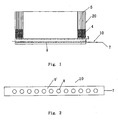
- a conventional micro-channel heat exchanger 20 generally comprises micro-channels or flat tubes 5, fins 4 disposed between the adjacent micro-channels or flat tubes 5, an inlet manifold 3 and an outlet manifold (not shown) disposed at ends of the micro-channels or flat tubes 5 respectively, and a refrigerant distributor 10 disposed in the inlet manifold 3 as shown in Figs. 1-2 .
- the refrigerant distributor 10 is disposed at a side of the heat exchanger 20 to distribute refrigerant.
- the distributor 10 may have a portion extending out of the inlet manifold 3 as shown in Fig. 1 or may have no portion extending out of the inlet manifold 3.
- the refrigerant distributor 10 comprises a pipe 9' in which a plurality of outlets 8 are formed in an axial direction of the pipe 9'.
- a refrigerant distributor 10 has been proposed as shown in Fig. 2 .
- the distributor 10 is formed by a cylindrical pipe in which a plurality of outlets 8 are formed through a wall of the cylindrical pipe. Assuming that refrigerant enters into the distributor 10 from an inlet 7 shown in Fig. 2 , the refrigerant flows along an inner chamber of the distributor, is ejected out of the pipe through the outlets 8, and then is mixed. After that, the mixed refrigerant flows into the flat tubes 5.
- the distributor is disadvantageous in that refrigerant is layered when it flows in the distributing pipe. The liquid refrigerant is located on a lower side and the gaseous refrigerant is located on an upper side due to the gravity.
- a refrigerant distributor for a heat exchanger.
- the refrigerant distributor comprises: a pipe for distributing refrigerant.
- the pipe has a channel therein in which the refrigerant flows.
- the channel has at least one portion having reduced cross-section area, for example, between an end and another end of the pipe.
- the at least one portion having reduced cross-section area is a reducing segment formed by reducing a size of the pipe in a direction generally perpendicular to an axial direction of the pipe.
- the pipe may be a cylindrical pipe and the size is a diameter.
- the at least one portion having reduced cross-section area is a flat segment formed by pressing the portion of the pipe to be flat.
- the at least one portion having reduced cross-section area is a reducing segment formed by pressing an outer peripheral surface of the portion of the pipe.
- the at least one portion having reduced cross-section area is formed by a raised portion projecting inward from an inner wall of the pipe.
- the pipe has an inlet disposed at the end of the pipe and the refrigerant flows into the pipe through the inlet.
- the at least one portion having reduced cross-section area comprises a plurality of portions having reduced cross-section area. Distances between the adjacent portions having reduced cross-section area of the plurality of portions having reduced cross-section area gradually increase from the end to the other end of the pipe.
- the at least one portion having reduced cross-section area comprises a plurality of portions having reduced cross-section area. Distances between the adjacent portions having reduced cross-section area of the plurality of portions having reduced cross-section area are generally equal.
- At least one outlet is disposed between every two adjacent portions having reduced cross-section area of the plurality of portions having reduced cross-section area such that the refrigerant flows out of the pipe through the at least one outlet.
- the pipe has a plurality of outlets through which the refrigerant flows out of the pipe, the at least one portion having reduced cross-section area comprises a plurality of portions having reduced cross-section area, and a plurality of the portions having reduced cross-section area such as two portions having reduced cross-section area are disposed between every two adjacent outlets of the plurality of outlets.
- a heat exchanger comprising a refrigerant distributor disposed at a side of the heat exchanger to distribute refrigerant, wherein the refrigerant distributor is one of the distributors mentioned above.
- the heat exchanger may be a micro-channel heat exchanger.
- the refrigerant distributor alleviates the layering of refrigerant flowing in a distributing pipe and mixes the vapor-liquid refrigerant relatively uniformly.
- a micro-channel heat exchanger 2 according to the first embodiment of the present invention comprises micro-channels or flat tubes 5, fins 4 disposed between the adjacent micro-channels or flat tubes 5, an inlet manifold 3 and an outlet manifold (not shown) disposed at ends of the micro-channels or flat tubes 5 respectively, and a refrigerant distributor 1 disposed in the inlet manifold 3 as shown in Figs. 3-6 .
- the refrigerant distributor 1 is disposed at a side of the heat exchanger 2 to distribute refrigerant.
- the refrigerant distributor 1 for the heat exchanger comprises a pipe 9 for distributing refrigerant as shown in Figs. 3-6 .
- the pipe 9 has a channel 91 therein in which the refrigerant flows.
- the channel 91 has at least one portion having reduced cross-section area 6.
- the pipe 9 may be a cylindrical pipe.
- the pipe 9 further comprises a plurality of outlets 8 from which the refrigerant flows out of the pipe 9, and an inlet 7 through which the refrigerant flows into the pipe 9.
- At least one outlet 8 is disposed between every two adjacent portions having reduced cross-section area 6 of the plurality of portions having reduced cross-section area 6.
- one portion having reduced cross-section area 6, or a plurality of the portions having reduced cross-section area 6 such as two portions having reduced cross-section area are disposed between every two adjacent outlets 8 of the plurality of outlets 8.
- the portions having reduced cross-section area 6 may be reducing segments 6 formed by reducing a size of the pipe 9 in a direction generally perpendicular to an axial direction of the pipe 9 as shown in Figs. 3-6 .
- the portions having reduced cross-section area 6 may be the reducing segments 6 formed by pressing an outer peripheral surface of the portions of the pipe 9.
- a diameter D2 of segments of a cylindrical pipe 9 positioned at intervals in a longitudinal direction of the cylindrical pipe 9 is reduced to a predetermined diameter D1 to form the reducing segments 6 as an example of the portions having reduced cross-section area, that is, D2 ⁇ D1.
- the outlets 8 are arranged through walls of the unreduced portions of the pipe 9.
- the refrigerant ejects every time it passes through one of the reducing segments 6.
- the vapor-liquid refrigerant is mixed uniformly.
- a part of the mixed refrigerant is ejected out of the pipe 9 through the outlets 8 in the unreduced portions of the pipe 9, and the remaining refrigerant continues advancing and is ejected again when flowing through the next reducing segment.
- the refrigerant is ejected multiple times through the reducing segments to be mixed more uniformly.
- two or more portions having reduced cross-section area 6 may be disposed between every two adjacent outlets 8 to eject the vapor-liquid fluid multiple times such that the vapor-liquid fluid is mixed uniformly when it flows out of the pipe through the outlets 8.
- distances between the adjacent portions having reduced cross-section area may gradually increase from one end of the pipe, at which the inlet 7 is disposed, to the other end of the pipe, or the distances between the adjacent portions having reduced cross-section area may be generally equal.
- a refrigerant passes through the reducing segments 6 in a refrigerant flow direction R in which the refrigerant flows in the pipe 9, pressure loss occurs.
- the distances d1, d2, and d3 between the adjacent reducing segments may be given as d3 ⁇ d2 ⁇ d1.
- the distances become larger in the refrigerant flow direction, thereby reducing large pressure loss that is caused by excessive reducing segments through which the refrigerant passes due to excessive length of a distributor.
- a number of the reducing segments is not limited and may be determined according to actual conditions.
- Openings with a predetermined size as the outlets 8 are formed by punching at intervals through a wall of a common smooth cylindrical pipe. Then, reducing segments 6 are formed by pressing an outer peripheral surface of the cylindrical pipe at predetermined positions between the adjacent openings in such a way that a size of a cross-section of the pipe located at the predetermined positions is reduced to a required size.
- a number of the opening as the outlet 8 in each of the unreduced portions between the adjacent reducing segments 6 is not limited to one, but two or more openings as the outlets 8 may be disposed in each of the unreduced portions between the adjacent reducing segments 6.
- the specific positions of the openings may be any appropriate positions and are dependent upon specific conditions.
- the pipe may be a pipe such as a pipe having an elliptical cross-section, a flat pipe and the like instead of the cylindrical pipe.
- a cross-section shape of the pipe is not limited.
- the pipe may have any appropriate cross-section shape.
- the pipe is not limited to a straight pipe, but may be a pipe having any appropriate shape.
- the cylindrical pipe 9 shown in Figs. 4-6 does not contain the portion extending out of the heat exchanger 2 as shown in Fig. 3 .
- a heat exchanger 2' according to the second embodiment of the present invention is the same as that of the first embodiment except a refrigerant distributor 1'. Only the distributor 1' is described below in detail.
- the refrigerant distributor 1' comprises a cylindrical pipe 9 as shown in Figs. 7-10 .
- the pipe 9 comprises a plurality of outlets 8 through which the refrigerant flows out of the pipe 9.
- the distributor 1' according to the second embodiment is the same as the distributor 1 according to the first embodiment except that the flat segments 6' as an example of the portions having reduced cross-section area according to the second embodiment is different from the reducing segments 6 of the first embodiment.
- the portions having reduced cross-section area 6' are flat segments 6' formed by pressing the portions of the pipe to be flat.
- the flat segments 6' facilitate manufacturing of the distributor and may be formed in a flat duckbill shape as shown in Figs. 7-10 .
- the cylindrical pipe 9 shown in Figs. 8-10 does not contain the portion extending out of the heat exchanger 2' as shown in Fig. 7 .
- the distributor according to the present invention can be applied to any other appropriate heat exchangers except of the micro-channel heat exchanger.
- distributors 1" may be configured as shown in Figs. 11-13 , and the portions having reduced cross-section area of the distributors 1" may be formed by raised portions 6" projecting inward from an inner wall of the pipe 9 as shown in Figs. 11-13 .
- Each raised portion 6" may be formed at a complete inner perimeter of the inner wall of the pipe or at a part of the inner perimeter.
- a wall of a pipe partially projects inward at a part of an outer perimeter of the pipe instead of the wall of the pipe projecting inward at the complete outer perimeter of the pipe.
- the portions having reduced cross-section area according to the present invention may be formed in other manners to generate turbulent flow of refrigerant or to eject refrigerant.
- At least one portion having reduced cross-section area is located between both ends of the pipe.
- the portion having reduced cross-section area may be positioned at the end of the pipe where the inlet 7 is disposed, such that refrigerant supplied to the distributor through a piping can be mixed uniformly.
- the portion having reduced cross-section area is described for ejecting refrigerant.
- the portion having reduced cross-section area may be used to generate turbulent flow of refrigerant instead of ejection of refrigerant, or to mix refrigerant.
- outlets 8 are disposed towards a direction perpendicular to the flat tubes 5 only for the purpose of illustration. However, the outlets 8 may be disposed towards any appropriate direction relative to the flat tubes 5.
Landscapes
- Engineering & Computer Science (AREA)
- Physics & Mathematics (AREA)
- Thermal Sciences (AREA)
- Mechanical Engineering (AREA)
- General Engineering & Computer Science (AREA)
- Heat-Exchange Devices With Radiators And Conduit Assemblies (AREA)
- Details Of Heat-Exchange And Heat-Transfer (AREA)
Abstract
Description
- The present invention relates to a refrigerant distributor for a heat exchanger and a heat exchanger having the refrigerant distributor.
- A conventional
micro-channel heat exchanger 20 generally comprises micro-channels orflat tubes 5,fins 4 disposed between the adjacent micro-channels orflat tubes 5, aninlet manifold 3 and an outlet manifold (not shown) disposed at ends of the micro-channels orflat tubes 5 respectively, and arefrigerant distributor 10 disposed in theinlet manifold 3 as shown inFigs. 1-2 . Therefrigerant distributor 10 is disposed at a side of theheat exchanger 20 to distribute refrigerant. Thedistributor 10 may have a portion extending out of theinlet manifold 3 as shown inFig. 1 or may have no portion extending out of theinlet manifold 3. Therefrigerant distributor 10 comprises a pipe 9' in which a plurality ofoutlets 8 are formed in an axial direction of the pipe 9'. - If vapor-liquid phase refrigerant exists, distribution of the refrigerant shall be problematic. In order to distribute the vapor-liquid phase refrigerant, a
refrigerant distributor 10 has been proposed as shown inFig. 2 . Thedistributor 10 is formed by a cylindrical pipe in which a plurality ofoutlets 8 are formed through a wall of the cylindrical pipe. Assuming that refrigerant enters into thedistributor 10 from aninlet 7 shown inFig. 2 , the refrigerant flows along an inner chamber of the distributor, is ejected out of the pipe through theoutlets 8, and then is mixed. After that, the mixed refrigerant flows into theflat tubes 5. However, the distributor is disadvantageous in that refrigerant is layered when it flows in the distributing pipe. The liquid refrigerant is located on a lower side and the gaseous refrigerant is located on an upper side due to the gravity. - It is an object of the present invention to provide a refrigerant distributor for a heat exchanger and a heat exchanger having the refrigerant distributor which can alleviate the layering of refrigerant flowing in a distributing pipe.
- In accordance with an aspect of the present invention, there is provided a refrigerant distributor for a heat exchanger. The refrigerant distributor comprises: a pipe for distributing refrigerant. The pipe has a channel therein in which the refrigerant flows. The channel has at least one portion having reduced cross-section area, for example, between an end and another end of the pipe.
- In accordance with another aspect of the present invention, the at least one portion having reduced cross-section area is a reducing segment formed by reducing a size of the pipe in a direction generally perpendicular to an axial direction of the pipe.
- The pipe may be a cylindrical pipe and the size is a diameter.
- In accordance with a further aspect of the present invention, the at least one portion having reduced cross-section area is a flat segment formed by pressing the portion of the pipe to be flat.
- In accordance with a still further aspect of the present invention, the at least one portion having reduced cross-section area is a reducing segment formed by pressing an outer peripheral surface of the portion of the pipe.
- In accordance with a further aspect of the present invention, the at least one portion having reduced cross-section area is formed by a raised portion projecting inward from an inner wall of the pipe.
- In accordance with an aspect of the present invention, the pipe has an inlet disposed at the end of the pipe and the refrigerant flows into the pipe through the inlet. The at least one portion having reduced cross-section area comprises a plurality of portions having reduced cross-section area. Distances between the adjacent portions having reduced cross-section area of the plurality of portions having reduced cross-section area gradually increase from the end to the other end of the pipe.
- In accordance with another aspect of the present invention, the at least one portion having reduced cross-section area comprises a plurality of portions having reduced cross-section area. Distances between the adjacent portions having reduced cross-section area of the plurality of portions having reduced cross-section area are generally equal.
- In accordance with an aspect of the present invention, at least one outlet is disposed between every two adjacent portions having reduced cross-section area of the plurality of portions having reduced cross-section area such that the refrigerant flows out of the pipe through the at least one outlet. In accordance with an alternative aspect of the present invention, the pipe has a plurality of outlets through which the refrigerant flows out of the pipe, the at least one portion having reduced cross-section area comprises a plurality of portions having reduced cross-section area, and a plurality of the portions having reduced cross-section area such as two portions having reduced cross-section area are disposed between every two adjacent outlets of the plurality of outlets.
- In accordance with an aspect of the present invention, there is provided a heat exchanger. The heat exchanger comprises a refrigerant distributor disposed at a side of the heat exchanger to distribute refrigerant, wherein the refrigerant distributor is one of the distributors mentioned above.
- The heat exchanger may be a micro-channel heat exchanger.
- With the above configuration, the refrigerant distributor alleviates the layering of refrigerant flowing in a distributing pipe and mixes the vapor-liquid refrigerant relatively uniformly.
- These and/or other aspects and advantages of the present invention will become apparent and more readily appreciated from the following description of the embodiments, taken in conjunction with the accompanying drawing.
-
Fig. 1 is a schematic view showing a conventional micro-channel heat exchanger. -
Fig. 2 is a schematic view showing a conventional refrigerant distributor. -
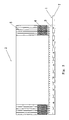
Fig. 3 is a schematic view showing a micro-channel heat exchanger according to a first embodiment of the present invention. -
Fig. 4 is a schematic front view showing a refrigerant distributor according to the first embodiment of the present invention. -
Fig. 5 is a schematic top view of the refrigerant distributor shown inFig. 4 . -
Fig. 6 is a schematic perspective view of the refrigerant distributor shown inFig. 4 . -
Fig. 7 is a schematic view showing a micro-channel heat exchanger according to a second embodiment of the present invention. -
Fig. 8 is a schematic perspective view showing a refrigerant distributor according to the second embodiment of the present invention. -
Fig. 9 is a schematic front view of the refrigerant distributor shown inFig. 8 . -
Fig. 10 is a schematic top perspective view of the refrigerant distributor shown inFig. 8 . -
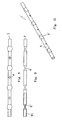
Figs. 11-13 are schematic views showing a refrigerant distributor according to further embodiments of the present invention. - The embodiments are described below in order to explain the present invention, but do not pose a limitation on the scope of the invention.
- A
micro-channel heat exchanger 2 according to the first embodiment of the present invention comprises micro-channels orflat tubes 5,fins 4 disposed between the adjacent micro-channels orflat tubes 5, aninlet manifold 3 and an outlet manifold (not shown) disposed at ends of the micro-channels orflat tubes 5 respectively, and arefrigerant distributor 1 disposed in theinlet manifold 3 as shown inFigs. 3-6 . Therefrigerant distributor 1 is disposed at a side of theheat exchanger 2 to distribute refrigerant. - The
refrigerant distributor 1 for the heat exchanger comprises apipe 9 for distributing refrigerant as shown inFigs. 3-6 . Thepipe 9 has achannel 91 therein in which the refrigerant flows. Thechannel 91 has at least one portion having reducedcross-section area 6. Thepipe 9 may be a cylindrical pipe. Thepipe 9 further comprises a plurality ofoutlets 8 from which the refrigerant flows out of thepipe 9, and aninlet 7 through which the refrigerant flows into thepipe 9. At least oneoutlet 8 is disposed between every two adjacent portions having reducedcross-section area 6 of the plurality of portions having reducedcross-section area 6. Alternatively, one portion having reducedcross-section area 6, or a plurality of the portions having reducedcross-section area 6 such as two portions having reduced cross-section area are disposed between every twoadjacent outlets 8 of the plurality ofoutlets 8. - The portions having reduced
cross-section area 6 may be reducingsegments 6 formed by reducing a size of thepipe 9 in a direction generally perpendicular to an axial direction of thepipe 9 as shown inFigs. 3-6 . The portions having reducedcross-section area 6 may be the reducingsegments 6 formed by pressing an outer peripheral surface of the portions of thepipe 9. For example, a diameter D2 of segments of acylindrical pipe 9 positioned at intervals in a longitudinal direction of thecylindrical pipe 9 is reduced to a predetermined diameter D1 to form the reducingsegments 6 as an example of the portions having reduced cross-section area, that is, D2 < D1. Theoutlets 8 are arranged through walls of the unreduced portions of thepipe 9. - Assuming that refrigerant enters into the
distributor 1 through theinlet 7, the refrigerant ejects every time it passes through one of the reducingsegments 6. As a result, the vapor-liquid refrigerant is mixed uniformly. A part of the mixed refrigerant is ejected out of thepipe 9 through theoutlets 8 in the unreduced portions of thepipe 9, and the remaining refrigerant continues advancing and is ejected again when flowing through the next reducing segment. The refrigerant is ejected multiple times through the reducing segments to be mixed more uniformly. - In order that a vapor-liquid fluid flowing in the
pipe 9 is sufficiently mixed before it arrives at thenext outlet 8, two or more portions having reducedcross-section area 6 may be disposed between every twoadjacent outlets 8 to eject the vapor-liquid fluid multiple times such that the vapor-liquid fluid is mixed uniformly when it flows out of the pipe through theoutlets 8. - According to an example of the embodiment of the present invention, distances between the adjacent portions having reduced cross-section area may gradually increase from one end of the pipe, at which the
inlet 7 is disposed, to the other end of the pipe, or the distances between the adjacent portions having reduced cross-section area may be generally equal. When a refrigerant passes through the reducingsegments 6 in a refrigerant flow direction R in which the refrigerant flows in thepipe 9, pressure loss occurs. As shown inFig. 4 , the distances d1, d2, and d3 between the adjacent reducing segments may be given as d3 ≤ d2 ≤ d1. In other words, the distances become larger in the refrigerant flow direction, thereby reducing large pressure loss that is caused by excessive reducing segments through which the refrigerant passes due to excessive length of a distributor. A number of the reducing segments is not limited and may be determined according to actual conditions. Alternatively, the reducing segments may be arranged at generally equal intervals, that is, the distances d1, d2, and d3 between the adjacent reducing segments may be given as d1 = d2 = d3. - An example of a method of manufacturing the distributor is described below. Openings with a predetermined size as the
outlets 8 are formed by punching at intervals through a wall of a common smooth cylindrical pipe. Then, reducingsegments 6 are formed by pressing an outer peripheral surface of the cylindrical pipe at predetermined positions between the adjacent openings in such a way that a size of a cross-section of the pipe located at the predetermined positions is reduced to a required size. - A number of the opening as the
outlet 8 in each of the unreduced portions between the adjacent reducingsegments 6 is not limited to one, but two or more openings as theoutlets 8 may be disposed in each of the unreduced portions between the adjacent reducingsegments 6. The specific positions of the openings may be any appropriate positions and are dependent upon specific conditions. - In the above embodiment, alternatively, the pipe may be a pipe such as a pipe having an elliptical cross-section, a flat pipe and the like instead of the cylindrical pipe. A cross-section shape of the pipe is not limited. The pipe may have any appropriate cross-section shape. In addition, the pipe is not limited to a straight pipe, but may be a pipe having any appropriate shape.
- The
cylindrical pipe 9 shown inFigs. 4-6 does not contain the portion extending out of theheat exchanger 2 as shown inFig. 3 . - A heat exchanger 2' according to the second embodiment of the present invention is the same as that of the first embodiment except a refrigerant distributor 1'. Only the distributor 1' is described below in detail.
- The refrigerant distributor 1' comprises a
cylindrical pipe 9 as shown inFigs. 7-10 . Thepipe 9 comprises a plurality ofoutlets 8 through which the refrigerant flows out of thepipe 9. The distributor 1' according to the second embodiment is the same as thedistributor 1 according to the first embodiment except that the flat segments 6' as an example of the portions having reduced cross-section area according to the second embodiment is different from the reducingsegments 6 of the first embodiment. The portions having reduced cross-section area 6' are flat segments 6' formed by pressing the portions of the pipe to be flat. The flat segments 6' facilitate manufacturing of the distributor and may be formed in a flat duckbill shape as shown inFigs. 7-10 . - The
cylindrical pipe 9 shown inFigs. 8-10 does not contain the portion extending out of the heat exchanger 2' as shown inFig. 7 . - Although the embodiments in which the distributor according to the present invention is used in the micro-channel heat exchanger have been described, the distributor according to the present invention can be applied to any other appropriate heat exchangers except of the micro-channel heat exchanger.
- In addition, the embodiments have been described and shown for the purpose of explanation of the present invention, but should not be construed as limitation to the present invention. For example,
distributors 1" according to further embodiments may be configured as shown inFigs. 11-13 , and the portions having reduced cross-section area of thedistributors 1" may be formed by raisedportions 6" projecting inward from an inner wall of thepipe 9 as shown inFigs. 11-13 . Each raisedportion 6" may be formed at a complete inner perimeter of the inner wall of the pipe or at a part of the inner perimeter. For example, a wall of a pipe partially projects inward at a part of an outer perimeter of the pipe instead of the wall of the pipe projecting inward at the complete outer perimeter of the pipe. In addition, the portions having reduced cross-section area according to the present invention may be formed in other manners to generate turbulent flow of refrigerant or to eject refrigerant. - In the above embodiments, at least one portion having reduced cross-section area is located between both ends of the pipe. Alternatively, the portion having reduced cross-section area may be positioned at the end of the pipe where the
inlet 7 is disposed, such that refrigerant supplied to the distributor through a piping can be mixed uniformly. - In addition, in the above embodiments, the portion having reduced cross-section area is described for ejecting refrigerant. However, the portion having reduced cross-section area may be used to generate turbulent flow of refrigerant instead of ejection of refrigerant, or to mix refrigerant.
- In addition, in
Figs. 3 and7 , theoutlets 8 are disposed towards a direction perpendicular to theflat tubes 5 only for the purpose of illustration. However, theoutlets 8 may be disposed towards any appropriate direction relative to theflat tubes 5.
Claims (14)
- A refrigerant distributor for a heat exchanger, comprising:a pipe for distributing a refrigerant, the pipe having a channel therein in which the refrigerant flows,wherein the channel has at least one portion having reduced cross-section area.
- The refrigerant distributor for a heat exchanger according to claim 1, wherein the at least one portion having reduced cross-section area is a reducing segment formed by reducing a size of the pipe in a direction generally perpendicular to an axial direction of the pipe.
- The refrigerant distributor for a heat exchanger according to claim 1, wherein the pipe is a cylindrical pipe and the size is a diameter.
- The refrigerant distributor for a heat exchanger according to claim 1, wherein the at least one portion having reduced cross-section area is a flat segment formed by pressing the portion of the pipe to be flat.
- The refrigerant distributor for a heat exchanger according to claim 1, wherein the at least one portion having reduced cross-section area is a reducing segment formed by pressing an outer peripheral surface of the portion of the pipe.
- The refrigerant distributor for a heat exchanger according to claim 1, wherein the at least one portion having reduced cross-section area is formed by a raised portion projecting inward from an inner wall of the pipe.
- The refrigerant distributor for a heat exchanger according to claim 1, wherein the at least one portion having reduced cross-section area is disposed between an end and another end of the pipe.
- The refrigerant distributor for a heat exchanger according to claim 7, wherein the pipe has an inlet disposed at the end of the pipe, the refrigerant flows into the pipe through the inlet, the at least one portion having reduced cross-section area comprises a plurality of portions having reduced cross-section area, and distances between the adjacent portions having reduced cross-section area of the plurality of portions having reduced cross-section area gradually increase from the end to the other end of the pipe.
- The refrigerant distributor for a heat exchanger according to claim 7, wherein the at least one portion having reduced cross-section area comprises a plurality of portions having reduced cross-section area, and distances between the adjacent portions having reduced cross-section area of the plurality of portions having reduced cross-section area are generally equal.
- The refrigerant distributor for a heat exchanger according to claim 8, wherein at least one outlet is disposed between every two adjacent portions having reduced cross-section area of the plurality of portions having reduced cross-section area such that the refrigerant flows out of the pipe through the at least one outlet.
- The refrigerant distributor for a heat exchanger according to claim 1, wherein the at least one portion having reduced cross-section area comprises a plurality of portions having reduced cross-section area, the pipe has a plurality of outlets through which the refrigerant flows out of the pipe, and a plurality of the portions having reduced cross-section area are disposed between every two adjacent outlets of the plurality of outlets.
- The refrigerant distributor for a heat exchanger according to claim 1, wherein the at least one portion having reduced cross-section area comprises a plurality of portions having reduced cross-section area, the pipe has a plurality of outlets through which the refrigerant flows out of the pipe, and two portions having reduced cross-section area are disposed between every two adjacent outlets of the plurality of outlets.
- A heat exchanger, comprising:a refrigerant distributor disposed at a side of the heat exchanger to distribute refrigerant,wherein the refrigerant distributor is the refrigerant distributor according to any one of claims 1-12.
- The heat exchanger according to claim 13, wherein the heat exchanger is a micro-channel heat exchanger.
Applications Claiming Priority (1)
| Application Number | Priority Date | Filing Date | Title |
|---|---|---|---|
| CN2009101320097A CN101788243B (en) | 2009-04-03 | 2009-04-03 | Refrigerant distributor for heat exchanger and heat exchanger |
Publications (3)
| Publication Number | Publication Date |
|---|---|
| EP2241852A2 true EP2241852A2 (en) | 2010-10-20 |
| EP2241852A3 EP2241852A3 (en) | 2014-01-15 |
| EP2241852B1 EP2241852B1 (en) | 2015-06-10 |
Family
ID=42263908
Family Applications (1)
| Application Number | Title | Priority Date | Filing Date |
|---|---|---|---|
| EP10003238.2A Not-in-force EP2241852B1 (en) | 2009-04-03 | 2010-03-26 | Refrigerant distributor for heat exchanger and heat exchanger |
Country Status (3)
| Country | Link |
|---|---|
| US (1) | US9423190B2 (en) |
| EP (1) | EP2241852B1 (en) |
| CN (1) | CN101788243B (en) |
Cited By (2)
| Publication number | Priority date | Publication date | Assignee | Title |
|---|---|---|---|---|
| FR3075348A1 (en) * | 2017-12-19 | 2019-06-21 | Valeo Systemes Thermiques | DEVICE FOR DISPENSING A REFRIGERANT FLUID FOR BEING LOOSE IN A COLLECTOR BOX OF A HEAT EXCHANGER |
| EP3805687A4 (en) * | 2018-06-11 | 2021-06-16 | Mitsubishi Electric Corporation | REFRIGERANT DISPENSER, HEAT EXCHANGER AND AIR CONDITIONER |
Families Citing this family (17)
| Publication number | Priority date | Publication date | Assignee | Title |
|---|---|---|---|---|
| CN101788242A (en) * | 2009-03-25 | 2010-07-28 | 三花丹佛斯(杭州)微通道换热器有限公司 | Refrigerant distributor for heat exchanger and heat exchanger |
| CN101922882B (en) * | 2010-09-13 | 2011-12-28 | 三花丹佛斯(杭州)微通道换热器有限公司 | Refrigerant conduit and heat exchanger with same |
| CN102079038B (en) | 2010-12-08 | 2013-02-13 | 三花控股集团有限公司 | Heat exchanger and refrigerant diversion tube thereof as well as method for processing refrigerant diversion tube |
| DE102012205771A1 (en) * | 2012-04-10 | 2013-10-10 | Siemens Aktiengesellschaft | Heat storage for power plant services |
| EP2674715A1 (en) * | 2012-06-14 | 2013-12-18 | Alfa Laval Corporate AB | A plate heat exchanger with thermally drilled hole |
| CN103411463A (en) * | 2013-08-27 | 2013-11-27 | 杭州三花微通道换热器有限公司 | Refrigerant distribution component, collecting pipe assembly and heat exchanger |
| EP3314191B1 (en) * | 2015-06-29 | 2020-09-30 | Carrier Corporation | Two phase distributor evaporator |
| CN107543336A (en) * | 2016-06-23 | 2018-01-05 | 杭州三花家电热管理系统有限公司 | Header and the heat exchanger with the header |
| JP6639690B2 (en) * | 2016-09-23 | 2020-02-05 | 東芝キヤリア株式会社 | Heat exchanger and refrigeration cycle device |
| WO2018204808A1 (en) * | 2017-05-05 | 2018-11-08 | Carrier Corporation | Heat exchanger for heat pump applications |
| US10982870B2 (en) * | 2018-08-31 | 2021-04-20 | Jonhson Controls Technology Company | Working fluid distribution systems |
| CN110940220B (en) * | 2018-09-25 | 2022-03-01 | 丹佛斯有限公司 | Distribution tube assembly for heat exchanger and header assembly and heat exchanger having the same |
| CN111288833B (en) * | 2018-12-06 | 2022-03-15 | 丹佛斯有限公司 | Collecting pipe assembly and heat exchanger |
| CN112815752B (en) * | 2020-12-31 | 2022-09-20 | 北京航空航天大学 | Thermal control system of two-phase fluid heat exchange loop of spacecraft |
| CN116817628B (en) * | 2022-04-22 | 2026-06-16 | 浙江三花智能控制股份有限公司 | heat exchanger |
| WO2024084543A1 (en) * | 2022-10-17 | 2024-04-25 | 三菱電機株式会社 | Refrigeration cycle device, heat exchanger, and refrigerant distributor |
| US12566035B2 (en) * | 2022-12-23 | 2026-03-03 | Carrier Corporation | Simple distributor for inlet manifold of microchannel heat exchanger |
Family Cites Families (29)
| Publication number | Priority date | Publication date | Assignee | Title |
|---|---|---|---|---|
| US1315853A (en) * | 1919-09-09 | Kabii bvaiid nokduitg and bttben bagnab | ||
| US1662236A (en) * | 1926-09-11 | 1928-03-13 | Edmund Mcgillivray | Steam and hot-water radiator |
| US2252045A (en) * | 1938-10-18 | 1941-08-12 | Spanner Edward Frank | Tubular heat exchange apparatus |
| US2942858A (en) * | 1958-04-21 | 1960-06-28 | American Air Filter Co | Heat exchange apparatus |
| US3026092A (en) * | 1958-08-18 | 1962-03-20 | Marlo Coil Company | Heat exchanger |
| US3232341A (en) * | 1960-02-01 | 1966-02-01 | Garrett Corp | Condenser |
| US3826304A (en) * | 1967-10-11 | 1974-07-30 | Universal Oil Prod Co | Advantageous configuration of tubing for internal boiling |
| US3976128A (en) * | 1975-06-12 | 1976-08-24 | Ford Motor Company | Plate and fin heat exchanger |
| WO1995002159A1 (en) * | 1993-07-03 | 1995-01-19 | Ernst Flitsch Gmbh & Co. | Device for distributing refrigerating medium in an evaporator |
| JP3216960B2 (en) | 1994-09-19 | 2001-10-09 | 株式会社日立製作所 | Outdoor unit and indoor unit of air conditioner and refrigerant distributor used for them |
| US6363965B1 (en) * | 1998-08-25 | 2002-04-02 | Eaton Aeroquip Inc. | Manifold assembly |
| CA2289428C (en) * | 1998-12-04 | 2008-12-09 | Beckett Gas, Inc. | Heat exchanger tube with integral restricting and turbulating structure |
| DE10100241A1 (en) * | 2001-01-05 | 2002-07-18 | Hde Metallwerk Gmbh | Heat exchanger tube for liquid or gaseous media |
| US6729386B1 (en) * | 2001-01-22 | 2004-05-04 | Stanley H. Sather | Pulp drier coil with improved header |
| US7017656B2 (en) * | 2001-05-24 | 2006-03-28 | Honeywell International, Inc. | Heat exchanger with manifold tubes for stiffening and load bearing |
| JP2004278935A (en) * | 2003-03-17 | 2004-10-07 | Calsonic Kansei Corp | Evaporator |
| EP1548380A3 (en) * | 2003-12-22 | 2006-10-04 | Hussmann Corporation | Flat-tube evaporator with micro-distributor |
| US7086249B2 (en) * | 2004-10-01 | 2006-08-08 | Advanced Heat Transfer, Llc | Refrigerant distribution device and method |
| US7398819B2 (en) * | 2004-11-12 | 2008-07-15 | Carrier Corporation | Minichannel heat exchanger with restrictive inserts |
| TWM267829U (en) * | 2004-11-24 | 2005-06-11 | Forward Electronics Co Ltd | Liquid cooling pipe having internal separation plate in liquid-cooling type heat sink |
| KR100908769B1 (en) * | 2005-02-02 | 2009-07-22 | 캐리어 코포레이션 | Co-current heat exchangers and methods to promote uniform refrigerant flow |
| US7275394B2 (en) * | 2005-04-22 | 2007-10-02 | Visteon Global Technologies, Inc. | Heat exchanger having a distributer plate |
| EP1798507A2 (en) * | 2005-12-13 | 2007-06-20 | Behr GmbH & Co. KG | Heat exchanger, more particularly evaporator |
| DE102006016839B4 (en) * | 2006-04-07 | 2025-10-30 | Att Automotivethermotech Gmbh | Oil-coolant heat exchangers for motor vehicles |
| EA014861B1 (en) * | 2006-05-30 | 2011-02-28 | Необульб Текнолоджиз Инк. | High-power and high heat-dissipating light emitting diode illuminating equipment |
| CN200949725Y (en) * | 2006-06-10 | 2007-09-19 | 戴丁军 | Liquid dispenser |
| US20080013278A1 (en) * | 2006-06-30 | 2008-01-17 | Fredric Landry | Reservoir for liquid cooling systems used to provide make-up fluid and trap gas bubbles |
| WO2008060270A1 (en) * | 2006-11-13 | 2008-05-22 | Carrier Corporation | Minichannel heat exchanger header insert for distribution |
| CA2718767C (en) * | 2008-04-18 | 2016-09-06 | Shell Internationale Research Maatschappij B.V. | Using mines and tunnels for treating subsurface hydrocarbon containing formations |
-
2009
- 2009-04-03 CN CN2009101320097A patent/CN101788243B/en not_active Expired - Fee Related
-
2010
- 2010-03-26 EP EP10003238.2A patent/EP2241852B1/en not_active Not-in-force
- 2010-03-31 US US12/751,311 patent/US9423190B2/en not_active Expired - Fee Related
Non-Patent Citations (1)
| Title |
|---|
| None |
Cited By (2)
| Publication number | Priority date | Publication date | Assignee | Title |
|---|---|---|---|---|
| FR3075348A1 (en) * | 2017-12-19 | 2019-06-21 | Valeo Systemes Thermiques | DEVICE FOR DISPENSING A REFRIGERANT FLUID FOR BEING LOOSE IN A COLLECTOR BOX OF A HEAT EXCHANGER |
| EP3805687A4 (en) * | 2018-06-11 | 2021-06-16 | Mitsubishi Electric Corporation | REFRIGERANT DISPENSER, HEAT EXCHANGER AND AIR CONDITIONER |
Also Published As
| Publication number | Publication date |
|---|---|
| US20100252243A1 (en) | 2010-10-07 |
| EP2241852A3 (en) | 2014-01-15 |
| US9423190B2 (en) | 2016-08-23 |
| EP2241852B1 (en) | 2015-06-10 |
| CN101788243A (en) | 2010-07-28 |
| CN101788243B (en) | 2011-09-28 |
Similar Documents
| Publication | Publication Date | Title |
|---|---|---|
| EP2241852B1 (en) | Refrigerant distributor for heat exchanger and heat exchanger | |
| EP2236973B1 (en) | Refrigerant distributer for heat exchanger and heat exchanger | |
| US9528778B2 (en) | Refrigerant guiding pipe and heat exchanger having refrigerant guiding pipe | |
| EP2889570B1 (en) | Heat exchanger | |
| US8485248B2 (en) | Flow distributor for a heat exchanger assembly | |
| EP1884733B1 (en) | Heat exchanger assembly with partitioned manifolds | |
| CN104154801B (en) | Collecting pipe and heat exchanger | |
| EP2278246A2 (en) | Multi-channel heat exchanger with improved uniformity of refrigerant fluid distribution | |
| US11592244B2 (en) | Multiport fluid distributor and microchannel heat exchanger having the same | |
| CN104380023B (en) | Heat-exchangers of the plate type with injection apparatus | |
| EP2878911B1 (en) | Heat exchanger | |
| EP3314191B1 (en) | Two phase distributor evaporator | |
| CN101922882A (en) | Refrigerant conduit and heat exchanger having the same | |
| CN105258411B (en) | Gas-liquid separation pipe and heat exchanger for heat exchanger | |
| KR20120044848A (en) | Heat exchanger and micro-channel tube for the same | |
| CN103604254A (en) | Built-in gas-liquid flow distribution structure | |
| CN116221968A (en) | Heat exchanger and air conditioning system | |
| CN102954627B (en) | Heat exchanger | |
| CN216205612U (en) | Distribution structure and plate heat exchanger with same | |
| JP7102434B2 (en) | Heat exchanger with liquid / gas mixer with improved opening | |
| US20170321969A1 (en) | Fin for a finned pack for heat exchangers, as well as heat exchanger | |
| US20200109894A1 (en) | Heat exchanger with a liquid/gas mixing device with improved channel geometry | |
| CN209877733U (en) | Gas-liquid distributor and heat exchanger thereof | |
| US20250283673A1 (en) | Laminated header for a microchannel heat exchanger | |
| CN118548744A (en) | Distributing pipe and heat exchanger with same |
Legal Events
| Date | Code | Title | Description |
|---|---|---|---|
| PUAI | Public reference made under article 153(3) epc to a published international application that has entered the european phase |
Free format text: ORIGINAL CODE: 0009012 |
|
| AK | Designated contracting states |
Kind code of ref document: A2 Designated state(s): AT BE BG CH CY CZ DE DK EE ES FI FR GB GR HR HU IE IS IT LI LT LU LV MC MK MT NL NO PL PT RO SE SI SK SM TR |
|
| AX | Request for extension of the european patent |
Extension state: AL BA ME RS |
|
| RAP1 | Party data changed (applicant data changed or rights of an application transferred) |
Owner name: SANHUA HOLDING GROUP CO., LTD. Owner name: DANFOSS A/S |
|
| PUAL | Search report despatched |
Free format text: ORIGINAL CODE: 0009013 |
|
| AK | Designated contracting states |
Kind code of ref document: A3 Designated state(s): AT BE BG CH CY CZ DE DK EE ES FI FR GB GR HR HU IE IS IT LI LT LU LV MC MK MT NL NO PL PT RO SE SI SK SM TR |
|
| AX | Request for extension of the european patent |
Extension state: AL BA ME RS |
|
| RIC1 | Information provided on ipc code assigned before grant |
Ipc: F28F 9/02 20060101AFI20131206BHEP Ipc: F25B 39/02 20060101ALI20131206BHEP |
|
| RBV | Designated contracting states (corrected) |
Designated state(s): AT BE BG CH CY CZ DE DK EE ES FI FR GB GR HR HU IE IS IT LI LT LU LV MC MK MT NL NO PL PT RO SE SI SK SM TR |
|
| 17P | Request for examination filed |
Effective date: 20140710 |
|
| GRAP | Despatch of communication of intention to grant a patent |
Free format text: ORIGINAL CODE: EPIDOSNIGR1 |
|
| INTG | Intention to grant announced |
Effective date: 20150220 |
|
| GRAS | Grant fee paid |
Free format text: ORIGINAL CODE: EPIDOSNIGR3 |
|
| RAP1 | Party data changed (applicant data changed or rights of an application transferred) |
Owner name: SANHUA (HANGZHOU) MICRO CHANNEL HEAT EXCHANGER CO. Owner name: DANFOSS A/S |
|
| GRAA | (expected) grant |
Free format text: ORIGINAL CODE: 0009210 |
|
| AK | Designated contracting states |
Kind code of ref document: B1 Designated state(s): AT BE BG CH CY CZ DE DK EE ES FI FR GB GR HR HU IE IS IT LI LT LU LV MC MK MT NL NO PL PT RO SE SI SK SM TR |
|
| REG | Reference to a national code |
Ref country code: GB Ref legal event code: FG4D |
|
| REG | Reference to a national code |
Ref country code: CH Ref legal event code: EP |
|
| REG | Reference to a national code |
Ref country code: AT Ref legal event code: REF Ref document number: 731091 Country of ref document: AT Kind code of ref document: T Effective date: 20150715 |
|
| REG | Reference to a national code |
Ref country code: DE Ref legal event code: R096 Ref document number: 602010025129 Country of ref document: DE |
|
| REG | Reference to a national code |
Ref country code: IE Ref legal event code: FG4D |
|
| REG | Reference to a national code |
Ref country code: DE Ref legal event code: R082 Ref document number: 602010025129 Country of ref document: DE Representative=s name: PATENTANWAELTE DR. KNOBLAUCH PARTGMBB, DE |
|
| PG25 | Lapsed in a contracting state [announced via postgrant information from national office to epo] |
Ref country code: LT Free format text: LAPSE BECAUSE OF FAILURE TO SUBMIT A TRANSLATION OF THE DESCRIPTION OR TO PAY THE FEE WITHIN THE PRESCRIBED TIME-LIMIT Effective date: 20150610 Ref country code: FI Free format text: LAPSE BECAUSE OF FAILURE TO SUBMIT A TRANSLATION OF THE DESCRIPTION OR TO PAY THE FEE WITHIN THE PRESCRIBED TIME-LIMIT Effective date: 20150610 Ref country code: ES Free format text: LAPSE BECAUSE OF FAILURE TO SUBMIT A TRANSLATION OF THE DESCRIPTION OR TO PAY THE FEE WITHIN THE PRESCRIBED TIME-LIMIT Effective date: 20150610 Ref country code: NO Free format text: LAPSE BECAUSE OF FAILURE TO SUBMIT A TRANSLATION OF THE DESCRIPTION OR TO PAY THE FEE WITHIN THE PRESCRIBED TIME-LIMIT Effective date: 20150910 |
|
| REG | Reference to a national code |
Ref country code: AT Ref legal event code: MK05 Ref document number: 731091 Country of ref document: AT Kind code of ref document: T Effective date: 20150610 |
|
| REG | Reference to a national code |
Ref country code: NL Ref legal event code: MP Effective date: 20150610 |
|
| PG25 | Lapsed in a contracting state [announced via postgrant information from national office to epo] |
Ref country code: BG Free format text: LAPSE BECAUSE OF FAILURE TO SUBMIT A TRANSLATION OF THE DESCRIPTION OR TO PAY THE FEE WITHIN THE PRESCRIBED TIME-LIMIT Effective date: 20150910 Ref country code: GR Free format text: LAPSE BECAUSE OF FAILURE TO SUBMIT A TRANSLATION OF THE DESCRIPTION OR TO PAY THE FEE WITHIN THE PRESCRIBED TIME-LIMIT Effective date: 20150911 Ref country code: LV Free format text: LAPSE BECAUSE OF FAILURE TO SUBMIT A TRANSLATION OF THE DESCRIPTION OR TO PAY THE FEE WITHIN THE PRESCRIBED TIME-LIMIT Effective date: 20150610 |
|
| PG25 | Lapsed in a contracting state [announced via postgrant information from national office to epo] |
Ref country code: EE Free format text: LAPSE BECAUSE OF FAILURE TO SUBMIT A TRANSLATION OF THE DESCRIPTION OR TO PAY THE FEE WITHIN THE PRESCRIBED TIME-LIMIT Effective date: 20150610 |
|
| PG25 | Lapsed in a contracting state [announced via postgrant information from national office to epo] |
Ref country code: RO Free format text: LAPSE BECAUSE OF NON-PAYMENT OF DUE FEES Effective date: 20150610 Ref country code: SK Free format text: LAPSE BECAUSE OF FAILURE TO SUBMIT A TRANSLATION OF THE DESCRIPTION OR TO PAY THE FEE WITHIN THE PRESCRIBED TIME-LIMIT Effective date: 20150610 Ref country code: PT Free format text: LAPSE BECAUSE OF FAILURE TO SUBMIT A TRANSLATION OF THE DESCRIPTION OR TO PAY THE FEE WITHIN THE PRESCRIBED TIME-LIMIT Effective date: 20151012 Ref country code: PL Free format text: LAPSE BECAUSE OF FAILURE TO SUBMIT A TRANSLATION OF THE DESCRIPTION OR TO PAY THE FEE WITHIN THE PRESCRIBED TIME-LIMIT Effective date: 20150610 Ref country code: AT Free format text: LAPSE BECAUSE OF FAILURE TO SUBMIT A TRANSLATION OF THE DESCRIPTION OR TO PAY THE FEE WITHIN THE PRESCRIBED TIME-LIMIT Effective date: 20150610 Ref country code: IS Free format text: LAPSE BECAUSE OF FAILURE TO SUBMIT A TRANSLATION OF THE DESCRIPTION OR TO PAY THE FEE WITHIN THE PRESCRIBED TIME-LIMIT Effective date: 20151010 Ref country code: CZ Free format text: LAPSE BECAUSE OF FAILURE TO SUBMIT A TRANSLATION OF THE DESCRIPTION OR TO PAY THE FEE WITHIN THE PRESCRIBED TIME-LIMIT Effective date: 20150610 |
|
| REG | Reference to a national code |
Ref country code: DE Ref legal event code: R097 Ref document number: 602010025129 Country of ref document: DE |
|
| REG | Reference to a national code |
Ref country code: FR Ref legal event code: PLFP Year of fee payment: 7 |
|
| PLBE | No opposition filed within time limit |
Free format text: ORIGINAL CODE: 0009261 |
|
| STAA | Information on the status of an ep patent application or granted ep patent |
Free format text: STATUS: NO OPPOSITION FILED WITHIN TIME LIMIT |
|
| PG25 | Lapsed in a contracting state [announced via postgrant information from national office to epo] |
Ref country code: DK Free format text: LAPSE BECAUSE OF FAILURE TO SUBMIT A TRANSLATION OF THE DESCRIPTION OR TO PAY THE FEE WITHIN THE PRESCRIBED TIME-LIMIT Effective date: 20150610 |
|
| 26N | No opposition filed |
Effective date: 20160311 |
|
| PG25 | Lapsed in a contracting state [announced via postgrant information from national office to epo] |
Ref country code: SI Free format text: LAPSE BECAUSE OF FAILURE TO SUBMIT A TRANSLATION OF THE DESCRIPTION OR TO PAY THE FEE WITHIN THE PRESCRIBED TIME-LIMIT Effective date: 20150610 |
|
| PG25 | Lapsed in a contracting state [announced via postgrant information from national office to epo] |
Ref country code: BE Free format text: LAPSE BECAUSE OF NON-PAYMENT OF DUE FEES Effective date: 20160331 |
|
| PG25 | Lapsed in a contracting state [announced via postgrant information from national office to epo] |
Ref country code: LU Free format text: LAPSE BECAUSE OF FAILURE TO SUBMIT A TRANSLATION OF THE DESCRIPTION OR TO PAY THE FEE WITHIN THE PRESCRIBED TIME-LIMIT Effective date: 20160326 Ref country code: MC Free format text: LAPSE BECAUSE OF FAILURE TO SUBMIT A TRANSLATION OF THE DESCRIPTION OR TO PAY THE FEE WITHIN THE PRESCRIBED TIME-LIMIT Effective date: 20150610 |
|
| REG | Reference to a national code |
Ref country code: CH Ref legal event code: PL |
|
| GBPC | Gb: european patent ceased through non-payment of renewal fee |
Effective date: 20160326 |
|
| REG | Reference to a national code |
Ref country code: IE Ref legal event code: MM4A |
|
| PG25 | Lapsed in a contracting state [announced via postgrant information from national office to epo] |
Ref country code: BE Free format text: LAPSE BECAUSE OF FAILURE TO SUBMIT A TRANSLATION OF THE DESCRIPTION OR TO PAY THE FEE WITHIN THE PRESCRIBED TIME-LIMIT Effective date: 20150610 |
|
| PG25 | Lapsed in a contracting state [announced via postgrant information from national office to epo] |
Ref country code: GB Free format text: LAPSE BECAUSE OF NON-PAYMENT OF DUE FEES Effective date: 20160326 Ref country code: LI Free format text: LAPSE BECAUSE OF NON-PAYMENT OF DUE FEES Effective date: 20160331 Ref country code: IE Free format text: LAPSE BECAUSE OF NON-PAYMENT OF DUE FEES Effective date: 20160326 Ref country code: CH Free format text: LAPSE BECAUSE OF NON-PAYMENT OF DUE FEES Effective date: 20160331 |
|
| REG | Reference to a national code |
Ref country code: FR Ref legal event code: PLFP Year of fee payment: 8 |
|
| PG25 | Lapsed in a contracting state [announced via postgrant information from national office to epo] |
Ref country code: NL Free format text: LAPSE BECAUSE OF FAILURE TO SUBMIT A TRANSLATION OF THE DESCRIPTION OR TO PAY THE FEE WITHIN THE PRESCRIBED TIME-LIMIT Effective date: 20150610 Ref country code: SE Free format text: LAPSE BECAUSE OF FAILURE TO SUBMIT A TRANSLATION OF THE DESCRIPTION OR TO PAY THE FEE WITHIN THE PRESCRIBED TIME-LIMIT Effective date: 20150610 |
|
| PG25 | Lapsed in a contracting state [announced via postgrant information from national office to epo] |
Ref country code: MT Free format text: LAPSE BECAUSE OF FAILURE TO SUBMIT A TRANSLATION OF THE DESCRIPTION OR TO PAY THE FEE WITHIN THE PRESCRIBED TIME-LIMIT Effective date: 20150610 |
|
| REG | Reference to a national code |
Ref country code: FR Ref legal event code: PLFP Year of fee payment: 9 |
|
| PG25 | Lapsed in a contracting state [announced via postgrant information from national office to epo] |
Ref country code: HU Free format text: LAPSE BECAUSE OF FAILURE TO SUBMIT A TRANSLATION OF THE DESCRIPTION OR TO PAY THE FEE WITHIN THE PRESCRIBED TIME-LIMIT; INVALID AB INITIO Effective date: 20100326 Ref country code: SM Free format text: LAPSE BECAUSE OF FAILURE TO SUBMIT A TRANSLATION OF THE DESCRIPTION OR TO PAY THE FEE WITHIN THE PRESCRIBED TIME-LIMIT Effective date: 20150610 Ref country code: CY Free format text: LAPSE BECAUSE OF FAILURE TO SUBMIT A TRANSLATION OF THE DESCRIPTION OR TO PAY THE FEE WITHIN THE PRESCRIBED TIME-LIMIT Effective date: 20150610 |
|
| PG25 | Lapsed in a contracting state [announced via postgrant information from national office to epo] |
Ref country code: HR Free format text: LAPSE BECAUSE OF FAILURE TO SUBMIT A TRANSLATION OF THE DESCRIPTION OR TO PAY THE FEE WITHIN THE PRESCRIBED TIME-LIMIT Effective date: 20150610 Ref country code: MK Free format text: LAPSE BECAUSE OF FAILURE TO SUBMIT A TRANSLATION OF THE DESCRIPTION OR TO PAY THE FEE WITHIN THE PRESCRIBED TIME-LIMIT Effective date: 20150610 Ref country code: MT Free format text: LAPSE BECAUSE OF FAILURE TO SUBMIT A TRANSLATION OF THE DESCRIPTION OR TO PAY THE FEE WITHIN THE PRESCRIBED TIME-LIMIT Effective date: 20160331 Ref country code: TR Free format text: LAPSE BECAUSE OF FAILURE TO SUBMIT A TRANSLATION OF THE DESCRIPTION OR TO PAY THE FEE WITHIN THE PRESCRIBED TIME-LIMIT Effective date: 20150610 |
|
| REG | Reference to a national code |
Ref country code: DE Ref legal event code: R082 Ref document number: 602010025129 Country of ref document: DE Representative=s name: KEIL & SCHAAFHAUSEN PATENTANWAELTE PARTGMBB, DE Ref country code: DE Ref legal event code: R082 Ref document number: 602010025129 Country of ref document: DE Representative=s name: KEIL & SCHAAFHAUSEN PATENT- UND RECHTSANWAELTE, DE |
|
| PGFP | Annual fee paid to national office [announced via postgrant information from national office to epo] |
Ref country code: DE Payment date: 20220331 Year of fee payment: 13 |
|
| PGFP | Annual fee paid to national office [announced via postgrant information from national office to epo] |
Ref country code: FR Payment date: 20220309 Year of fee payment: 13 |
|
| PGFP | Annual fee paid to national office [announced via postgrant information from national office to epo] |
Ref country code: IT Payment date: 20220330 Year of fee payment: 13 |
|
| REG | Reference to a national code |
Ref country code: DE Ref legal event code: R119 Ref document number: 602010025129 Country of ref document: DE |
|
| PG25 | Lapsed in a contracting state [announced via postgrant information from national office to epo] |
Ref country code: FR Free format text: LAPSE BECAUSE OF NON-PAYMENT OF DUE FEES Effective date: 20230331 Ref country code: DE Free format text: LAPSE BECAUSE OF NON-PAYMENT OF DUE FEES Effective date: 20231003 |
|
| PG25 | Lapsed in a contracting state [announced via postgrant information from national office to epo] |
Ref country code: IT Free format text: LAPSE BECAUSE OF NON-PAYMENT OF DUE FEES Effective date: 20230326 |