EP2241804A1 - Lighting system - Google Patents
Lighting system Download PDFInfo
- Publication number
- EP2241804A1 EP2241804A1 EP10160093A EP10160093A EP2241804A1 EP 2241804 A1 EP2241804 A1 EP 2241804A1 EP 10160093 A EP10160093 A EP 10160093A EP 10160093 A EP10160093 A EP 10160093A EP 2241804 A1 EP2241804 A1 EP 2241804A1
- Authority
- EP
- European Patent Office
- Prior art keywords
- lighting
- light
- electric
- distribution element
- feed
- Prior art date
- Legal status (The legal status is an assumption and is not a legal conclusion. Google has not performed a legal analysis and makes no representation as to the accuracy of the status listed.)
- Withdrawn
Links
- 230000003750 conditioning effect Effects 0.000 description 3
- 238000012986 modification Methods 0.000 description 3
- 230000004048 modification Effects 0.000 description 3
- 238000001514 detection method Methods 0.000 description 2
- 229910052736 halogen Inorganic materials 0.000 description 2
- 150000002367 halogens Chemical class 0.000 description 2
- 230000002035 prolonged effect Effects 0.000 description 2
- 230000009467 reduction Effects 0.000 description 2
- 239000000725 suspension Substances 0.000 description 2
- 230000004913 activation Effects 0.000 description 1
- 238000007792 addition Methods 0.000 description 1
- 230000005540 biological transmission Effects 0.000 description 1
- 239000003086 colorant Substances 0.000 description 1
- 239000012141 concentrate Substances 0.000 description 1
- 230000001419 dependent effect Effects 0.000 description 1
- 238000010586 diagram Methods 0.000 description 1
- 238000007726 management method Methods 0.000 description 1
- 230000009466 transformation Effects 0.000 description 1
Images

Classifications
-
- F—MECHANICAL ENGINEERING; LIGHTING; HEATING; WEAPONS; BLASTING
- F21—LIGHTING
- F21S—NON-PORTABLE LIGHTING DEVICES; SYSTEMS THEREOF; VEHICLE LIGHTING DEVICES SPECIALLY ADAPTED FOR VEHICLE EXTERIORS
- F21S8/00—Lighting devices intended for fixed installation
- F21S8/04—Lighting devices intended for fixed installation intended only for mounting on a ceiling or the like overhead structures
- F21S8/06—Lighting devices intended for fixed installation intended only for mounting on a ceiling or the like overhead structures by suspension
-
- F—MECHANICAL ENGINEERING; LIGHTING; HEATING; WEAPONS; BLASTING
- F21—LIGHTING
- F21S—NON-PORTABLE LIGHTING DEVICES; SYSTEMS THEREOF; VEHICLE LIGHTING DEVICES SPECIALLY ADAPTED FOR VEHICLE EXTERIORS
- F21S2/00—Systems of lighting devices, not provided for in main groups F21S4/00 - F21S10/00 or F21S19/00, e.g. of modular construction
-
- H—ELECTRICITY
- H05—ELECTRIC TECHNIQUES NOT OTHERWISE PROVIDED FOR
- H05B—ELECTRIC HEATING; ELECTRIC LIGHT SOURCES NOT OTHERWISE PROVIDED FOR; CIRCUIT ARRANGEMENTS FOR ELECTRIC LIGHT SOURCES, IN GENERAL
- H05B47/00—Circuit arrangements for operating light sources in general, i.e. where the type of light source is not relevant
- H05B47/10—Controlling the light source
- H05B47/155—Coordinated control of two or more light sources
-
- F—MECHANICAL ENGINEERING; LIGHTING; HEATING; WEAPONS; BLASTING
- F21—LIGHTING
- F21V—FUNCTIONAL FEATURES OR DETAILS OF LIGHTING DEVICES OR SYSTEMS THEREOF; STRUCTURAL COMBINATIONS OF LIGHTING DEVICES WITH OTHER ARTICLES, NOT OTHERWISE PROVIDED FOR
- F21V23/00—Arrangement of electric circuit elements in or on lighting devices
- F21V23/04—Arrangement of electric circuit elements in or on lighting devices the elements being switches
- F21V23/0435—Arrangement of electric circuit elements in or on lighting devices the elements being switches activated by remote control means
-
- F—MECHANICAL ENGINEERING; LIGHTING; HEATING; WEAPONS; BLASTING
- F21—LIGHTING
- F21Y—INDEXING SCHEME ASSOCIATED WITH SUBCLASSES F21K, F21L, F21S and F21V, RELATING TO THE FORM OR THE KIND OF THE LIGHT SOURCES OR OF THE COLOUR OF THE LIGHT EMITTED
- F21Y2115/00—Light-generating elements of semiconductor light sources
- F21Y2115/10—Light-emitting diodes [LED]
Definitions
- the present invention concerns a lighting device used in domestic, industrial and commercial spaces such as offices, shops, restaurants, gyms or others.
- the lighting device comprises a plurality of lighting bodies, preferably, but not only, of the LED type, monochromatic or with a chromatic variation.
- Lighting devices comprising a plurality of lighting bodies, each of which is provided with a source of light such as for example a halogen lamp, an incandescent lamp or other.
- the known lighting device also comprises at least an element for the distribution of electric energy, advantageously associated with a light point, mounted for example on a wall or a ceiling in correspondence with a predetermined seating provided for the delivery of electric energy from an electric plant.
- the distribution element is suitable to distribute electric energy to each of said lighting bodies by means of a predetermined electric connection which provides a plurality of cables, exiting substantially radially from the distribution element.
- Each electric cable is suitable to feed at least a predetermined lighting body.
- the electric connection between the various lighting bodies is obtained substantially by means of a parallel connection between the cables made in correspondence with the distribution element, thus providing the switching on, the switching off and/or the simultaneous variation in light intensity of all the bodies of the known lighting device.
- the electric connection is made by disposing each lighting body in a desired position, corresponding to a predetermined zone in the space to be lit, using the same electric cables as suspension members, assembling them in sight in a wall and/or a ceiling development and/or constraining them at predetermined suspension points. In this way it is possible to position the lighting bodies inside a space to be lit according to a desired disposition, allowing an effective lighting where it is actually desired and without making any modifications to the pre-existing electric plant.
- One disadvantage of the known lighting device is that it is not possible to modify individually the intensity of the stream of light emitted by each individual lighting body.
- One purpose of the present invention is to make a lighting device which allows to make individual modifications of the stream of light intensity emitted by each individual lighting body even when the corresponding sources of light are of the LED type.
- Another purpose of the present invention is to make a lighting device which allows to maintain constant the intensity of the stream of light emitted by each individual lighting body even for long intervals of functioning.
- the Applicant has devised, tested and embodied the present invention to overcome the shortcomings of the state of the art and to obtain these and other purposes and advantages.
- a lighting device can be used to light one or more spaces.
- the lighting device comprises a plurality of lighting bodies, each provided with at least a source of light, and suitable to light a predetermined zone of said one or more spaces.
- the lighting device also comprises an element for the distribution of electric energy, associated with a predetermined delivery seating of electric energy of the electric plant of the space to be lit.
- the distribution element is suitable to distribute electric energy to each of the lighting bodies by means of predetermined electric connections exiting from the distribution element toward each lighting body.
- the electric connections are used, in one embodiment of the invention, as members to assemble the lighting bodies to walls and/or ceilings of said one or more spaces so that each lighting body connected to said distribution element is associated with a corresponding zone to be lit.
- the at least one distribution element has its own electric feed means, and at least a microprocessor electronic card.
- the electric feed means are suitable to feed said lighting bodies independently from each other, so that each of them can be activated in a desired functioning condition to light said relative zone, on the basis of the programming which can be carried out on the microprocessor card.
- the feed means are suitable to selectively adjust, independently from each other, the amount of electric energy which feeds each lighting body connected to said distribution element, and, therefore, the stream of light emitted by the associated sources of light.
- At least some of the sources of light are lamps of the LED type.
- At least some of said LED lamps are of the RGB (Red, Green, Blue) and/or AWB (Amber, White, Blue) type.
- the distribution element also comprises sensor means, operatively associated with the feed means and with the electronic microprocessor card, able to detect, directly or indirectly, at least some of the functioning electrical quantities of each lighting body so as to allow to regulate the corresponding electric feed energy and substantially to maintain the stream of light constant over time at a predetermined emission value corresponding to a set functioning condition.
- the lighting device comprises remote command means, such as one or more remote controls or radio controls suitable to selectively activate the feed means.
- a lighting device 10 can be used to light one or more spaces 20, for example in domestic or commercial spaces, in shops, restaurants, gyms or other, or in industrial contexts.
- the lighting device 10 comprises (figs. 1A-1D, 2 , 3 and 5 ) a distribution element, or plate, 16, a plurality of lighting bodies 24, each provided with one or more sources of light, in this case LED elements 26, and an electronic card 30 of the microprocessor type, for light management purposes, incorporated into the plate 16, and to which the lighting bodies 24 are indirectly connected.
- the device 10 also comprises a remote command device, in this case a remote control 52 in radiofrequency, suitable to cooperate with the electronic card 30 to command the switching on, switching off and/or the adjustment of the light intensity of each LED element 26 as will be described in more detail hereafter.
- the LED element or elements 26 can be both monochromatic and with color variation, such as a LED unit with a set of three colors RGB or AWB.
- the plate 16 circular in shape, comprises a box-like containment body inside of which the electronic card 30 is housed.
- the plate 16 is suitable to be mounted, in a known manner, on a wall or on the ceiling 12 of the space 20 to be lit, substantially in correspondence with a seating for the delivery of electric tension of the electric lighting circuit, that is, a seating in which a corresponding wall or ceiling light point is substantially provided.
- the device 10 is normally fed at the alternating tension of the electric circuit and can be switched on or off by means of a corresponding group of switches and/or circuit breakers, not shown in the drawings, which are part of the lighting plant.
- the cables 18 are also used as attachment members to attach the lighting bodies 24 to a wall and/or ceiling.
- each cable 18 is laid and/or attached to the wall and/or ceiling and/or partially constrained at predetermined attachment points of the ceiling 12, by means of attachment pawls 28 or other.
- each lighting body 24 inside the space 20 it is possible to position, in a desired way, each lighting body 24 inside the space 20 to be lit, in order to concentrate the relative stream of light onto a predetermined area 22, such as the surface of a table, or work top or other.
- a predetermined area 22 such as the surface of a table, or work top or other.
- the electronic card 30 of the plate 16 ( fig. 4 ) comprises a control and processing unit, in this case a microprocessor unit 32 of the known type, for example 8 or 16 bit, suitable to command the activation, by means of corresponding command ports 34, of a plurality of tension regulators 40, or power drivers.
- Each regulator 40 is in turn suitable, as will be explained hereafter, to directly feed, at a desired feeding tension, a corresponding lighting body 24.
- each tension regulator 40 is able to deliver to each lighting body 24, that is to the relative sources 26, a variable current, depending on the intensity of light desired, having a maximum value of about 800mA with an exit tension of about 24V.
- the card 30 is also provided with a reference source 42 of direct tension, having a tension value suitable for the electric feed of the lighting bodies 24.
- the tension value is typically, for lighting elements with power LED, comprised in a range of about 24V.
- the tension source 42 can be part of a unit for the transformation and rectification of the alternate feed tension of the electric power supply of a known type, such as a transformer connected to a tension rectification bridge, from which the feed tension of the microprocessor unit 32 can also be derived.
- the feed source 42 is electrically connected to each of the tension regulators 40, in this case to a corresponding reference input (not shown), by means of a tension reference line 42a so as to supply to each regulator 40 a reference direct tension.
- Each regulator 40 is electrically connected by means of a command line 34a to a command port 34 of the microprocessor card 30 and at exit, by means of a corresponding feed line 40a, to the associated lighting body 24 so as to feed it with tension and current with the desired value and intensity.
- command ports 34 are independently commandable, for example according to a square wave pulse width modulation of the Pulse Width Modulation type (PWM), so as to drive each regulator 40 at a desired frequency,
- PWM Pulse Width Modulation type
- This allows to feed each LED element 26 with a predetermined feed current, substantially at the same frequency as the PWM output of the command port 34, so as to emit a corresponding stream of light of the desired intensity.
- the electronic card 30 also comprises a circuit to detect the electric power and development of the electrical quantities, for example tension or current, actually absorbed by each lighting body 24, that is, of the associated LED element 26.
- the electrical quantities are picked up in correspondence with a pick up point P of the feed line 40a and passed through a corresponding conditioning circuit 44 in order to condition the corresponding physical levels to a value compatible with those of the microprocessor unit 32.
- the exit of each conditioning circuit 44 is connected, through a feedback line 44a, to a corresponding detection port 36 of the microprocessor unit 32, for example provided with a square wave input PWM detector.
- the microprocessor unit 32 is able to regulate, that is, to keep the electrical quantities feeding each lighting body 24 substantially constant over time. This in turn ensures the emission of a stream of light that is constant over time, based both on possible settings of a user and also according to possible variations in the LEDs 26, due for example to thermal drift or other, which can cause a reduction in the stream of light, light fluttering phenomena, or unwanted changes in the color temperature of the LEDs.
- the plate 16 is also advantageously provided with a terminal board 29 ( figs. 4 and 5 ) having connection terminals 29a, two for each lighting body 24, electrically connected to a corresponding feed line 40a and suitable for the stable attachment of a relative feed cable 18.
- the plate 16 is also provided with cable clips 19, disposed substantially equally spaced on the external edge of the plate 16 and suitable to stably clamp each cable 18 so as to prevent the terminals 29a from possibly coming out during the assembly of the device 10. This allows to easily connect each lighting body 24 to the corresponding feed line 40a during the assembly of the device 10.
- the electronic card 30 is also provided with a radiofrequency interface 50 of a known type, electrically connected to a remote control port 38.
- the radiofrequency interface 50 is suitable to cooperate with the remote control 52 to receive different radiofrequency signals generated by the remote control 52 according to the specific key 52a that has been pushed.
- the radiofrequency signals are converted by the interface 50 into corresponding electric signals that are interpreted by the microprocessor unit 32 to activate the specific regulator 40.
- the frequency of communication of the radiofrequency signals is around 488 MHz. It is understood that the device 10 can be provided with two or more remote controls 52 to allow the device 10 to be managed by several users.
- the electronic card also comprises a multi switch 60, of the rotary dip switch type, directly connected in a known manner to one or more ports of the microprocessor unit 32, and suitable to be used to configure the device 10 dynamically, that is, to create a functional correspondence between each key 52a of the remote control 52 and a corresponding lighting body 24. In this way it is possible to univocally identify each lighting body 24, that is, a corresponding area 22, associating it substantially with one or more keys 52a.
- the device as described heretofore functions as follows.
- a specific radiofrequency signal is emitted, containing for example a predetermined identification code relating to the specific body 24, and a drive code, that is, a switch on or switch off code or, in the case of prolonged pressure on the key 52a, a code to vary the light intensity of the specific LED element 26.
- the radiofrequency signal is received by the radiofrequency interface 50 and is subsequently communicated to the microprocessor unit 32.
- the microprocessor unit 32 enables the corresponding tension regulator 40, piloting the associated command port 34 with a PWM signal having a square wave period that allows to deliver at output from the specific regulator 40 a predetermined electric feed current at a functioning tension that guarantees the emission of a desired stream of light intensity.
- the microprocessor unit 32 also detects continuously, by means of the detection ports 36, the conditioning circuit 44 and the feedback line 44a, the development of the PWM signals delivered by the corresponding regulator 40. This allows to detect possible variations with respect to the PWM signal generated by the command port 34, that is, variations in the electric feed or dimming quantities of the lighting bodies and therefore indirectly of the light intensity of the specific LED elements 26.
- the microprocessor unit is able to modify the PWM signals at inlet to the regulators 40 and hence feed each LED element 26 so as to obtain a desired stream of light intensity, substantially stable during functioning.
- the device 10 can provide to simultaneously switch on, switch off and/or continuously regulate the stream of light intensity of all the lighting bodies 24 controlled by the plate 16, by using specific dedicated keys 52a.
- the lighting bodies 24 can be grouped together functionally so as to allow them to be switched on or off, or the stream of light intensity varied in a substantially simultaneous manner.
- auxiliary lighting body 27 is disposed directly on the plate 16.
- a lamp 27 ( fig. 5 ) of the traditional type or halogen or LED can be mounted directly on the plate 16.
- he device 10 is also provided with a conveyed waves communication interface that allows, for example, cooperation with an automation plant and thus allows to feed each lighting body 24 according to one or more predefined functioning scenarios.
Landscapes
- Engineering & Computer Science (AREA)
- General Engineering & Computer Science (AREA)
- Circuit Arrangement For Electric Light Sources In General (AREA)
- Seal Device For Vehicle (AREA)
- Vehicle Body Suspensions (AREA)
- Polarising Elements (AREA)
Abstract
Lighting device used to light one or more spaces (20), comprising a plurality of lighting bodies (24), each provided with at least a source of light (26) to light a predetermined zone (22) of the one or more spaces (20). The lighting device comprises a distribution element (16) of electric energy, associated with a predetermined seat delivering electric energy of an electric plant of the space (20). The distribution element (16) is suitable to distribute electric energy to each lighting body (24) by means of electric connections (18) exiting from the distribution element (16) toward each lighting body (24). The distribution element (16) comprises feed means (40) to feed independently at least a relative lighting body (24) in a desired functioning condition in order to light the corresponding zone (22).
Description
- The present invention concerns a lighting device used in domestic, industrial and commercial spaces such as offices, shops, restaurants, gyms or others.
- The lighting device according to the present invention comprises a plurality of lighting bodies, preferably, but not only, of the LED type, monochromatic or with a chromatic variation.
- Lighting devices are known, comprising a plurality of lighting bodies, each of which is provided with a source of light such as for example a halogen lamp, an incandescent lamp or other. The known lighting device also comprises at least an element for the distribution of electric energy, advantageously associated with a light point, mounted for example on a wall or a ceiling in correspondence with a predetermined seating provided for the delivery of electric energy from an electric plant.
- The distribution element is suitable to distribute electric energy to each of said lighting bodies by means of a predetermined electric connection which provides a plurality of cables, exiting substantially radially from the distribution element. Each electric cable is suitable to feed at least a predetermined lighting body.
- The electric connection between the various lighting bodies is obtained substantially by means of a parallel connection between the cables made in correspondence with the distribution element, thus providing the switching on, the switching off and/or the simultaneous variation in light intensity of all the bodies of the known lighting device.
- It is also provided that the electric connection is made by disposing each lighting body in a desired position, corresponding to a predetermined zone in the space to be lit, using the same electric cables as suspension members, assembling them in sight in a wall and/or a ceiling development and/or constraining them at predetermined suspension points. In this way it is possible to position the lighting bodies inside a space to be lit according to a desired disposition, allowing an effective lighting where it is actually desired and without making any modifications to the pre-existing electric plant.
- One disadvantage of the known lighting device is that it is not possible to modify individually the intensity of the stream of light emitted by each individual lighting body.
- Moreover, it is not possible to control with precision possible variations in the currents absorbed by the lighting bodies during functioning. This causes inefficient performances of the lighting bodies, such as for example a reduction or increase of the stream of light during long periods of functioning, with respect to a stream of light value set when the known lighting device is switched on.
- One purpose of the present invention is to make a lighting device which allows to make individual modifications of the stream of light intensity emitted by each individual lighting body even when the corresponding sources of light are of the LED type.
- Another purpose of the present invention is to make a lighting device which allows to maintain constant the intensity of the stream of light emitted by each individual lighting body even for long intervals of functioning.
- The Applicant has devised, tested and embodied the present invention to overcome the shortcomings of the state of the art and to obtain these and other purposes and advantages.
- The present invention is set forth and characterized in the independent claim, while the dependent claims describe other characteristics of the invention or variants to the main inventive idea.
- In accordance with the above purposes, a lighting device according to the present invention can be used to light one or more spaces. The lighting device comprises a plurality of lighting bodies, each provided with at least a source of light, and suitable to light a predetermined zone of said one or more spaces.
- The lighting device also comprises an element for the distribution of electric energy, associated with a predetermined delivery seating of electric energy of the electric plant of the space to be lit. The distribution element is suitable to distribute electric energy to each of the lighting bodies by means of predetermined electric connections exiting from the distribution element toward each lighting body.
- The electric connections are used, in one embodiment of the invention, as members to assemble the lighting bodies to walls and/or ceilings of said one or more spaces so that each lighting body connected to said distribution element is associated with a corresponding zone to be lit.
- According to a characteristic feature of the present invention, the at least one distribution element has its own electric feed means, and at least a microprocessor electronic card. The electric feed means are suitable to feed said lighting bodies independently from each other, so that each of them can be activated in a desired functioning condition to light said relative zone, on the basis of the programming which can be carried out on the microprocessor card.
- According to the present invention, the feed means are suitable to selectively adjust, independently from each other, the amount of electric energy which feeds each lighting body connected to said distribution element, and, therefore, the stream of light emitted by the associated sources of light.
- According to another variant of the present invention, at least some of the sources of light are lamps of the LED type.
- According to another variant of the present invention at least some of said LED lamps are of the RGB (Red, Green, Blue) and/or AWB (Amber, White, Blue) type.
- Another variant of the present invention provides that the distribution element also comprises sensor means, operatively associated with the feed means and with the electronic microprocessor card, able to detect, directly or indirectly, at least some of the functioning electrical quantities of each lighting body so as to allow to regulate the corresponding electric feed energy and substantially to maintain the stream of light constant over time at a predetermined emission value corresponding to a set functioning condition.
- According to another variant of the present invention, the lighting device comprises remote command means, such as one or more remote controls or radio controls suitable to selectively activate the feed means.
- These and other characteristics of the present invention will become apparent from the following description of a preferential form of embodiment, given as a non-restrictive example with reference to the attached drawings wherein:
-
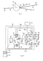
figs. 1A-1D are schematic drawings of lighting devices in different spaces; -
fig. 2 is a schematic lateral drawing of a lighting device according to the present invention; -
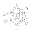
fig. 3 is a schematic view from below of the device infig. 2 ; -
fig. 4 is a block diagram of a detail of the lighting device according to the present invention; and -
fig. 5 is a schematic view of the device infig. 2 . - With reference to the attached drawings, a
lighting device 10 according to the present invention can be used to light one ormore spaces 20, for example in domestic or commercial spaces, in shops, restaurants, gyms or other, or in industrial contexts. - The
lighting device 10 comprises(figs. 1A-1D, 2 ,3 and5 ) a distribution element, or plate, 16, a plurality oflighting bodies 24, each provided with one or more sources of light, in thiscase LED elements 26, and anelectronic card 30 of the microprocessor type, for light management purposes, incorporated into theplate 16, and to which thelighting bodies 24 are indirectly connected. Thedevice 10 also comprises a remote command device, in this case aremote control 52 in radiofrequency, suitable to cooperate with theelectronic card 30 to command the switching on, switching off and/or the adjustment of the light intensity of eachLED element 26 as will be described in more detail hereafter. - The LED element or
elements 26 can be both monochromatic and with color variation, such as a LED unit with a set of three colors RGB or AWB. - The
plate 16, circular in shape, comprises a box-like containment body inside of which theelectronic card 30 is housed. Theplate 16 is suitable to be mounted, in a known manner, on a wall or on theceiling 12 of thespace 20 to be lit, substantially in correspondence with a seating for the delivery of electric tension of the electric lighting circuit, that is, a seating in which a corresponding wall or ceiling light point is substantially provided. - The
device 10 is normally fed at the alternating tension of the electric circuit and can be switched on or off by means of a corresponding group of switches and/or circuit breakers, not shown in the drawings, which are part of the lighting plant. - A plurality of
electric cables 18 of the low tension type, suitable to feed eachlighting body 24 electrically, exit from theplate 16 substantially radially and divergent from theplate 16. Thecables 18 are also used as attachment members to attach thelighting bodies 24 to a wall and/or ceiling. In this case eachcable 18 is laid and/or attached to the wall and/or ceiling and/or partially constrained at predetermined attachment points of theceiling 12, by means ofattachment pawls 28 or other. - In this way it is possible to position, in a desired way, each
lighting body 24 inside thespace 20 to be lit, in order to concentrate the relative stream of light onto apredetermined area 22, such as the surface of a table, or work top or other. This allows to distribute thelighting bodies 24 in an effective way with respect to a lighting system of the conventional type which uses lighting bodies substantially disposed in proximity to existing light points. - The
electronic card 30 of the plate 16 (fig. 4 ) comprises a control and processing unit, in this case amicroprocessor unit 32 of the known type, for example 8 or 16 bit, suitable to command the activation, by means ofcorresponding command ports 34, of a plurality oftension regulators 40, or power drivers. Eachregulator 40 is in turn suitable, as will be explained hereafter, to directly feed, at a desired feeding tension, acorresponding lighting body 24. Advantageously, eachtension regulator 40 is able to deliver to eachlighting body 24, that is to therelative sources 26, a variable current, depending on the intensity of light desired, having a maximum value of about 800mA with an exit tension of about 24V. - The
card 30 is also provided with areference source 42 of direct tension, having a tension value suitable for the electric feed of thelighting bodies 24. The tension value is typically, for lighting elements with power LED, comprised in a range of about 24V. - The
tension source 42 can be part of a unit for the transformation and rectification of the alternate feed tension of the electric power supply of a known type, such as a transformer connected to a tension rectification bridge, from which the feed tension of themicroprocessor unit 32 can also be derived. - The
feed source 42 is electrically connected to each of thetension regulators 40, in this case to a corresponding reference input (not shown), by means of atension reference line 42a so as to supply to eachregulator 40 a reference direct tension. - Each
regulator 40 is electrically connected by means of acommand line 34a to acommand port 34 of themicroprocessor card 30 and at exit, by means of acorresponding feed line 40a, to the associatedlighting body 24 so as to feed it with tension and current with the desired value and intensity. - Advantageously the
command ports 34 are independently commandable, for example according to a square wave pulse width modulation of the Pulse Width Modulation type (PWM), so as to drive eachregulator 40 at a desired frequency, This allows to feed eachLED element 26 with a predetermined feed current, substantially at the same frequency as the PWM output of thecommand port 34, so as to emit a corresponding stream of light of the desired intensity. - The
electronic card 30 also comprises a circuit to detect the electric power and development of the electrical quantities, for example tension or current, actually absorbed by eachlighting body 24, that is, of the associatedLED element 26. In fact, the electrical quantities are picked up in correspondence with a pick up point P of thefeed line 40a and passed through acorresponding conditioning circuit 44 in order to condition the corresponding physical levels to a value compatible with those of themicroprocessor unit 32. The exit of eachconditioning circuit 44 is connected, through afeedback line 44a, to acorresponding detection port 36 of themicroprocessor unit 32, for example provided with a square wave input PWM detector. - In this way, the
microprocessor unit 32, as will be described in more detail hereafter, is able to regulate, that is, to keep the electrical quantities feeding eachlighting body 24 substantially constant over time. This in turn ensures the emission of a stream of light that is constant over time, based both on possible settings of a user and also according to possible variations in theLEDs 26, due for example to thermal drift or other, which can cause a reduction in the stream of light, light fluttering phenomena, or unwanted changes in the color temperature of the LEDs. - The
plate 16 is also advantageously provided with a terminal board 29 (figs. 4 and5 ) having connection terminals 29a, two for eachlighting body 24, electrically connected to acorresponding feed line 40a and suitable for the stable attachment of arelative feed cable 18. Theplate 16 is also provided withcable clips 19, disposed substantially equally spaced on the external edge of theplate 16 and suitable to stably clamp eachcable 18 so as to prevent the terminals 29a from possibly coming out during the assembly of thedevice 10. This allows to easily connect eachlighting body 24 to thecorresponding feed line 40a during the assembly of thedevice 10. - The
electronic card 30 is also provided with aradiofrequency interface 50 of a known type, electrically connected to aremote control port 38. Theradiofrequency interface 50 is suitable to cooperate with theremote control 52 to receive different radiofrequency signals generated by theremote control 52 according to the specific key 52a that has been pushed. The radiofrequency signals are converted by theinterface 50 into corresponding electric signals that are interpreted by themicroprocessor unit 32 to activate thespecific regulator 40. - Advantageously the frequency of communication of the radiofrequency signals, that is, the frequency of transmission of the remote control and reception of the
interface 50, is around 488 MHz. It is understood that thedevice 10 can be provided with two or moreremote controls 52 to allow thedevice 10 to be managed by several users. - The electronic card also comprises a
multi switch 60, of the rotary dip switch type, directly connected in a known manner to one or more ports of themicroprocessor unit 32, and suitable to be used to configure thedevice 10 dynamically, that is, to create a functional correspondence between each key 52a of theremote control 52 and acorresponding lighting body 24. In this way it is possible to univocally identify eachlighting body 24, that is, a correspondingarea 22, associating it substantially with one ormore keys 52a. - The device as described heretofore functions as follows.
- When a user presses a predetermined key 52a of the
remote control 52, functionally corresponding to at least onepredetermined lighting body 24, a specific radiofrequency signal is emitted, containing for example a predetermined identification code relating to thespecific body 24, and a drive code, that is, a switch on or switch off code or, in the case of prolonged pressure on the key 52a, a code to vary the light intensity of thespecific LED element 26. - The radiofrequency signal is received by the
radiofrequency interface 50 and is subsequently communicated to themicroprocessor unit 32. For example when switching on, themicroprocessor unit 32 enables thecorresponding tension regulator 40, piloting the associatedcommand port 34 with a PWM signal having a square wave period that allows to deliver at output from thespecific regulator 40 a predetermined electric feed current at a functioning tension that guarantees the emission of a desired stream of light intensity. - The
microprocessor unit 32 also detects continuously, by means of thedetection ports 36, theconditioning circuit 44 and thefeedback line 44a, the development of the PWM signals delivered by the correspondingregulator 40. This allows to detect possible variations with respect to the PWM signal generated by thecommand port 34, that is, variations in the electric feed or dimming quantities of the lighting bodies and therefore indirectly of the light intensity of thespecific LED elements 26. - In addition it is possible to detect possible variations or disturbances of the feed tensions of the
LED elements 26, due for example to variations in their temperature during a prolonged period of functioning. - Therefore the microprocessor unit is able to modify the PWM signals at inlet to the
regulators 40 and hence feed eachLED element 26 so as to obtain a desired stream of light intensity, substantially stable during functioning. - It is understood that the
device 10 can provide to simultaneously switch on, switch off and/or continuously regulate the stream of light intensity of all thelighting bodies 24 controlled by theplate 16, by using specificdedicated keys 52a. - It also comes within the field of the present invention to provide that at least some of the
lighting bodies 24 can be grouped together functionally so as to allow them to be switched on or off, or the stream of light intensity varied in a substantially simultaneous manner. - It also comes within the field of the present invention to provide that an
auxiliary lighting body 27 is disposed directly on theplate 16. For example a lamp 27 (fig. 5 ) of the traditional type or halogen or LED can be mounted directly on theplate 16. - It also comes within the field of the present invention to provide that he
device 10 is also provided with a conveyed waves communication interface that allows, for example, cooperation with an automation plant and thus allows to feed eachlighting body 24 according to one or more predefined functioning scenarios. - It is clear that modifications and/or additions of parts may be made to the
lighting device 10 as described heretofore, without departing from the field and scope of the present invention. - It is also clear that, although the present invention has been described with reference to some specific examples, a person of skill in the art shall certainly be able to achieve many other equivalent forms of lighting device, having the characteristics as set forth in the claims and hence all coming within the field of protection defined thereby.
Claims (8)
- Lighting device used to light one or more spaces (20), comprising a plurality of lighting bodies (24), each associated with a zone (22) of said space (20), each lighting body (24) being provided with at least a source of light (26), the device comprising a distribution element (16) of electric energy, associated with a predetermined seat delivering electric energy of an electric plant of said space (20), and able to distribute electric energy to each of said lighting bodies (24) by means of electric connections (18) between said distribution element (16) and each lighting body (24), characterized in that said distribution element (16) of electric energy comprises electric feed means (40, 42) and a microprocessor electronic card (30), wherein said electric feed means comprise a reference source of direct tension (42) and a plurality of tension regulators (40), one for each lighting body (24) to be fed, connected to said source of direct tension (42), wherein said microprocessor electronic card (30) comprises a plurality of command ports (34), one for each lighting body (24), able to be independently modulated so as to drive each one of said tension regulators (40) at a desired frequency to regulate independently the stream of light emitted by each of said lighting bodies (24) and/or to keep constant over time the electric feed quantities of each of said lighting bodies (24).
- Device as in claim 1, characterized in that the distribution element (16) comprises sensor means (36, 44), operatively associated with the relative feed means (40, 42), able to detect, directly or indirectly, at least some of the functioning electrical quantities of each lighting body (24) in order to regulate the corresponding electric feed energy for each of said lighting bodies (24).
- Device as in claim 1, characterized in that at least some of the sources of light (26) are LED type lamps.
- Device as in claim 3, characterized in that at least some of said LED type lamps are RGB and/or AWB type.
- Device as in any claim hereinbefore, characterized in that it comprises remote command means (50) able to selectively activate said feed means (40).
- Device as in claim 5, characterized in that the remote command means comprise at least a radiofrequency remote control (52).
- Device as in claim 6, characterized in that it comprises configuration means (60) able to generate a functional correspondence between each key (52a) of the remote control (52) and at least an associated lighting body (24).
- Device as in any claim hereinbefore, characterized in that it comprises at least a light body (27) mounted on said distribution element (16).
Applications Claiming Priority (1)
| Application Number | Priority Date | Filing Date | Title |
|---|---|---|---|
| IT000078A ITUD20090078A1 (en) | 2009-04-17 | 2009-04-17 | LIGHTING DEVICE |
Publications (1)
| Publication Number | Publication Date |
|---|---|
| EP2241804A1 true EP2241804A1 (en) | 2010-10-20 |
Family
ID=41226305
Family Applications (1)
| Application Number | Title | Priority Date | Filing Date |
|---|---|---|---|
| EP10160093A Withdrawn EP2241804A1 (en) | 2009-04-17 | 2010-04-15 | Lighting system |
Country Status (2)
| Country | Link |
|---|---|
| EP (1) | EP2241804A1 (en) |
| IT (1) | ITUD20090078A1 (en) |
Citations (4)
| Publication number | Priority date | Publication date | Assignee | Title |
|---|---|---|---|---|
| EP0790457A2 (en) * | 1996-02-14 | 1997-08-20 | ARTEMIDE S.p.A. | Polychrome lighting device, particularly for the decorative lighting of rooms and the like |
| US6655817B2 (en) * | 2001-12-10 | 2003-12-02 | Tom Devlin | Remote controlled lighting apparatus and method |
| US20060113927A1 (en) * | 2004-12-01 | 2006-06-01 | Bondy Montgomery C | Multiple dimmer lighting system |
| WO2009021544A1 (en) * | 2007-08-10 | 2009-02-19 | Osram Gesellschaft mit beschränkter Haftung | Light for at least one led and transmitter for generating a radio signal for such a light |
Family Cites Families (2)
| Publication number | Priority date | Publication date | Assignee | Title |
|---|---|---|---|---|
| DE19716180A1 (en) * | 1997-04-18 | 1998-10-22 | Leonhard Bopp | Adjustable low voltage lamp unit |
| US20070222399A1 (en) * | 2004-12-01 | 2007-09-27 | Montgomery Bondy | Energy saving extra-low voltage dimmer lighting system |
-
2009
- 2009-04-17 IT IT000078A patent/ITUD20090078A1/en unknown
-
2010
- 2010-04-15 EP EP10160093A patent/EP2241804A1/en not_active Withdrawn
Patent Citations (4)
| Publication number | Priority date | Publication date | Assignee | Title |
|---|---|---|---|---|
| EP0790457A2 (en) * | 1996-02-14 | 1997-08-20 | ARTEMIDE S.p.A. | Polychrome lighting device, particularly for the decorative lighting of rooms and the like |
| US6655817B2 (en) * | 2001-12-10 | 2003-12-02 | Tom Devlin | Remote controlled lighting apparatus and method |
| US20060113927A1 (en) * | 2004-12-01 | 2006-06-01 | Bondy Montgomery C | Multiple dimmer lighting system |
| WO2009021544A1 (en) * | 2007-08-10 | 2009-02-19 | Osram Gesellschaft mit beschränkter Haftung | Light for at least one led and transmitter for generating a radio signal for such a light |
Also Published As
| Publication number | Publication date |
|---|---|
| ITUD20090078A1 (en) | 2010-10-18 |
Similar Documents
| Publication | Publication Date | Title |
|---|---|---|
| US10299321B1 (en) | Multi-channel white light tuning | |
| KR101648788B1 (en) | LED emotional lighting luminaire using both of correlated color temperature control and luminous flux control apparatus | |
| US20120062133A1 (en) | Low voltage led dimmer with integrated universal switch mode power supply | |
| RU2000132978A (en) | LED LIGHTING DEVICE WITH LIGHT RADIATION CONTROL | |
| KR20120068939A (en) | Lamp unit with a plurality of light source and toggle remote control method for selecting a drive setting therefor | |
| EP2747517A2 (en) | Lighting apparatus and lighting system | |
| JP5789727B1 (en) | Illuminance control device for LED stage lighting system using hybrid control system | |
| KR20100094692A (en) | Led illumination controller for transmitting | |
| US11683876B2 (en) | System for wireless control of electrical loads | |
| JP6617882B2 (en) | Lighting apparatus, lighting system, and lighting system setting method | |
| US10959314B2 (en) | Panel system having data signal transmission over power | |
| KR20240116120A (en) | Led light system capable of adjusting color temperature and brightness | |
| CN110431345A (en) | LED based lamps and lanterns | |
| US20200170089A1 (en) | Power supply system for a lighting system | |
| EP2241804A1 (en) | Lighting system | |
| KR101045976B1 (en) | Auto dimming system | |
| US11983973B2 (en) | System and scanning device for granting user access using a bluetooth low energy (BLE) Mesh | |
| US20080316003A1 (en) | Electric load control system having regional receivers | |
| JP6811424B2 (en) | Lighting control device and lighting system | |
| JP6422609B1 (en) | Load control system and installation method thereof | |
| JP2020009684A (en) | Load control system and load control device | |
| KR101698346B1 (en) | An ac wall switch performing led lights controls without supplemental power wires | |
| US11382193B1 (en) | Systems and methods related to photovoltaic direct drive lighting systems | |
| JP2017098144A (en) | Led illumination device and led illumination control device | |
| US9674932B1 (en) | Dual sensor lighting controller with 1-button remote control |
Legal Events
| Date | Code | Title | Description |
|---|---|---|---|
| PUAI | Public reference made under article 153(3) epc to a published international application that has entered the european phase |
Free format text: ORIGINAL CODE: 0009012 |
|
| AK | Designated contracting states |
Kind code of ref document: A1 Designated state(s): AT BE BG CH CY CZ DE DK EE ES FI FR GB GR HR HU IE IS IT LI LT LU LV MC MK MT NL NO PL PT RO SE SI SK SM TR |
|
| AX | Request for extension of the european patent |
Extension state: AL BA ME RS |
|
| STAA | Information on the status of an ep patent application or granted ep patent |
Free format text: STATUS: THE APPLICATION IS DEEMED TO BE WITHDRAWN |
|
| 18D | Application deemed to be withdrawn |
Effective date: 20110421 |