EP2241522A2 - Reduced feed roll wear using carbon nanotube additives in rubbers - Google Patents
Reduced feed roll wear using carbon nanotube additives in rubbers Download PDFInfo
- Publication number
- EP2241522A2 EP2241522A2 EP10158710A EP10158710A EP2241522A2 EP 2241522 A2 EP2241522 A2 EP 2241522A2 EP 10158710 A EP10158710 A EP 10158710A EP 10158710 A EP10158710 A EP 10158710A EP 2241522 A2 EP2241522 A2 EP 2241522A2
- Authority
- EP
- European Patent Office
- Prior art keywords
- rubber composition
- roll
- composite rubber
- carbon nanotubes
- soluble carbon
- Prior art date
- Legal status (The legal status is an assumption and is not a legal conclusion. Google has not performed a legal analysis and makes no representation as to the accuracy of the status listed.)
- Granted
Links
- 229920001971 elastomer Polymers 0.000 title claims abstract description 146
- 239000005060 rubber Substances 0.000 title claims abstract description 145
- OKTJSMMVPCPJKN-UHFFFAOYSA-N Carbon Chemical compound [C] OKTJSMMVPCPJKN-UHFFFAOYSA-N 0.000 title claims abstract description 106
- 239000002041 carbon nanotube Substances 0.000 title claims abstract description 100
- 229910021393 carbon nanotube Inorganic materials 0.000 title claims abstract description 100
- 239000000654 additive Substances 0.000 title 1
- 239000000203 mixture Substances 0.000 claims abstract description 105
- 239000002131 composite material Substances 0.000 claims abstract description 77
- 238000000034 method Methods 0.000 claims abstract description 27
- 238000004519 manufacturing process Methods 0.000 claims description 13
- -1 ethylene propylene diene Chemical class 0.000 claims description 10
- 229920002635 polyurethane Polymers 0.000 claims description 9
- 239000004814 polyurethane Substances 0.000 claims description 9
- 229920001296 polysiloxane Polymers 0.000 claims description 5
- RRHGJUQNOFWUDK-UHFFFAOYSA-N Isoprene Chemical compound CC(=C)C=C RRHGJUQNOFWUDK-UHFFFAOYSA-N 0.000 claims description 4
- 229920005549 butyl rubber Polymers 0.000 claims description 3
- VQTUBCCKSQIDNK-UHFFFAOYSA-N Isobutene Chemical group CC(C)=C VQTUBCCKSQIDNK-UHFFFAOYSA-N 0.000 claims description 2
- 238000000748 compression moulding Methods 0.000 claims description 2
- 150000001993 dienes Chemical class 0.000 claims description 2
- 229920005645 diorganopolysiloxane polymer Polymers 0.000 claims description 2
- 238000001746 injection moulding Methods 0.000 claims description 2
- 239000012948 isocyanate Substances 0.000 claims description 2
- 150000002513 isocyanates Chemical class 0.000 claims description 2
- 229920005862 polyol Polymers 0.000 claims description 2
- 150000003077 polyols Chemical class 0.000 claims description 2
- 125000000484 butyl group Chemical group [H]C([*])([H])C([H])([H])C([H])([H])C([H])([H])[H] 0.000 claims 1
- 238000001723 curing Methods 0.000 claims 1
- 238000000429 assembly Methods 0.000 abstract description 6
- 230000000712 assembly Effects 0.000 abstract description 6
- 238000013459 approach Methods 0.000 description 6
- 229910052799 carbon Inorganic materials 0.000 description 4
- 229910052751 metal Inorganic materials 0.000 description 4
- 239000002184 metal Substances 0.000 description 4
- 230000009467 reduction Effects 0.000 description 4
- 239000002109 single walled nanotube Substances 0.000 description 4
- 239000002904 solvent Substances 0.000 description 4
- 238000005299 abrasion Methods 0.000 description 3
- 230000015572 biosynthetic process Effects 0.000 description 3
- 239000002048 multi walled nanotube Substances 0.000 description 3
- 239000002071 nanotube Substances 0.000 description 3
- 239000013500 performance material Substances 0.000 description 3
- 229920000642 polymer Polymers 0.000 description 3
- 230000007928 solubilization Effects 0.000 description 3
- 238000005063 solubilization Methods 0.000 description 3
- 239000000126 substance Substances 0.000 description 3
- 238000003786 synthesis reaction Methods 0.000 description 3
- XMWRBQBLMFGWIX-UHFFFAOYSA-N C60 fullerene Chemical compound C12=C3C(C4=C56)=C7C8=C5C5=C9C%10=C6C6=C4C1=C1C4=C6C6=C%10C%10=C9C9=C%11C5=C8C5=C8C7=C3C3=C7C2=C1C1=C2C4=C6C4=C%10C6=C9C9=C%11C5=C5C8=C3C3=C7C1=C1C2=C4C6=C2C9=C5C3=C12 XMWRBQBLMFGWIX-UHFFFAOYSA-N 0.000 description 2
- HEDRZPFGACZZDS-UHFFFAOYSA-N Chloroform Chemical compound ClC(Cl)Cl HEDRZPFGACZZDS-UHFFFAOYSA-N 0.000 description 2
- 229910003481 amorphous carbon Inorganic materials 0.000 description 2
- 238000005229 chemical vapour deposition Methods 0.000 description 2
- 230000007547 defect Effects 0.000 description 2
- 239000006185 dispersion Substances 0.000 description 2
- 239000002079 double walled nanotube Substances 0.000 description 2
- 230000000694 effects Effects 0.000 description 2
- 229910003472 fullerene Inorganic materials 0.000 description 2
- 230000003993 interaction Effects 0.000 description 2
- 239000000463 material Substances 0.000 description 2
- VNWKTOKETHGBQD-UHFFFAOYSA-N methane Chemical compound C VNWKTOKETHGBQD-UHFFFAOYSA-N 0.000 description 2
- 238000012986 modification Methods 0.000 description 2
- 230000004048 modification Effects 0.000 description 2
- 239000002116 nanohorn Substances 0.000 description 2
- 229920000049 Carbon (fiber) Polymers 0.000 description 1
- JOYRKODLDBILNP-UHFFFAOYSA-N Ethyl urethane Chemical compound CCOC(N)=O JOYRKODLDBILNP-UHFFFAOYSA-N 0.000 description 1
- DBMJMQXJHONAFJ-UHFFFAOYSA-M Sodium laurylsulphate Chemical compound [Na+].CCCCCCCCCCCCOS([O-])(=O)=O DBMJMQXJHONAFJ-UHFFFAOYSA-M 0.000 description 1
- 238000005054 agglomeration Methods 0.000 description 1
- 230000002776 aggregation Effects 0.000 description 1
- 230000004075 alteration Effects 0.000 description 1
- 125000003118 aryl group Chemical group 0.000 description 1
- 239000011324 bead Substances 0.000 description 1
- 239000004917 carbon fiber Substances 0.000 description 1
- 239000002134 carbon nanofiber Substances 0.000 description 1
- 230000008859 change Effects 0.000 description 1
- 238000006243 chemical reaction Methods 0.000 description 1
- 238000010668 complexation reaction Methods 0.000 description 1
- 230000003247 decreasing effect Effects 0.000 description 1
- 238000011161 development Methods 0.000 description 1
- 238000009826 distribution Methods 0.000 description 1
- 239000000806 elastomer Substances 0.000 description 1
- 238000010891 electric arc Methods 0.000 description 1
- 125000000524 functional group Chemical group 0.000 description 1
- 239000010439 graphite Substances 0.000 description 1
- 229910002804 graphite Inorganic materials 0.000 description 1
- 238000010348 incorporation Methods 0.000 description 1
- 238000000608 laser ablation Methods 0.000 description 1
- 238000000465 moulding Methods 0.000 description 1
- 239000002102 nanobead Substances 0.000 description 1
- 229920000509 poly(aryleneethynylene) polymer Polymers 0.000 description 1
- 230000008569 process Effects 0.000 description 1
- 239000004094 surface-active agent Substances 0.000 description 1
Images



Classifications
-
- B—PERFORMING OPERATIONS; TRANSPORTING
- B65—CONVEYING; PACKING; STORING; HANDLING THIN OR FILAMENTARY MATERIAL
- B65H—HANDLING THIN OR FILAMENTARY MATERIAL, e.g. SHEETS, WEBS, CABLES
- B65H3/00—Separating articles from piles
- B65H3/02—Separating articles from piles using friction forces between articles and separator
- B65H3/06—Rollers or like rotary separators
- B65H3/0638—Construction of the rollers or like rotary separators
-
- B—PERFORMING OPERATIONS; TRANSPORTING
- B65—CONVEYING; PACKING; STORING; HANDLING THIN OR FILAMENTARY MATERIAL
- B65H—HANDLING THIN OR FILAMENTARY MATERIAL, e.g. SHEETS, WEBS, CABLES
- B65H2401/00—Materials used for the handling apparatus or parts thereof; Properties thereof
- B65H2401/10—Materials
- B65H2401/11—Polymer compositions
-
- B—PERFORMING OPERATIONS; TRANSPORTING
- B65—CONVEYING; PACKING; STORING; HANDLING THIN OR FILAMENTARY MATERIAL
- B65H—HANDLING THIN OR FILAMENTARY MATERIAL, e.g. SHEETS, WEBS, CABLES
- B65H2402/00—Constructional details of the handling apparatus
- B65H2402/80—Constructional details of the handling apparatus characterised by the manufacturing process
-
- B—PERFORMING OPERATIONS; TRANSPORTING
- B65—CONVEYING; PACKING; STORING; HANDLING THIN OR FILAMENTARY MATERIAL
- B65H—HANDLING THIN OR FILAMENTARY MATERIAL, e.g. SHEETS, WEBS, CABLES
- B65H2404/00—Parts for transporting or guiding the handled material
- B65H2404/10—Rollers
- B65H2404/11—Details of cross-section or profile
- B65H2404/111—Details of cross-section or profile shape
- B65H2404/1112—D-shape
-
- B—PERFORMING OPERATIONS; TRANSPORTING
- B65—CONVEYING; PACKING; STORING; HANDLING THIN OR FILAMENTARY MATERIAL
- B65H—HANDLING THIN OR FILAMENTARY MATERIAL, e.g. SHEETS, WEBS, CABLES
- B65H2404/00—Parts for transporting or guiding the handled material
- B65H2404/10—Rollers
- B65H2404/14—Roller pairs
-
- B—PERFORMING OPERATIONS; TRANSPORTING
- B65—CONVEYING; PACKING; STORING; HANDLING THIN OR FILAMENTARY MATERIAL
- B65H—HANDLING THIN OR FILAMENTARY MATERIAL, e.g. SHEETS, WEBS, CABLES
- B65H2404/00—Parts for transporting or guiding the handled material
- B65H2404/10—Rollers
- B65H2404/18—Rollers composed of several layers
- B65H2404/187—Rollers composed of several layers with wear resistance
-
- B—PERFORMING OPERATIONS; TRANSPORTING
- B65—CONVEYING; PACKING; STORING; HANDLING THIN OR FILAMENTARY MATERIAL
- B65H—HANDLING THIN OR FILAMENTARY MATERIAL, e.g. SHEETS, WEBS, CABLES
- B65H2404/00—Parts for transporting or guiding the handled material
- B65H2404/50—Surface of the elements in contact with the forwarded or guided material
- B65H2404/55—Built-up surface, e.g. arrangement for attaching the surface to the forwarding or guiding element
-
- B—PERFORMING OPERATIONS; TRANSPORTING
- B65—CONVEYING; PACKING; STORING; HANDLING THIN OR FILAMENTARY MATERIAL
- B65H—HANDLING THIN OR FILAMENTARY MATERIAL, e.g. SHEETS, WEBS, CABLES
- B65H2601/00—Problem to be solved or advantage achieved
- B65H2601/40—Increasing or maximizing
- B65H2601/42—Increasing or maximizing entities relating to the handling machine
- B65H2601/423—Life span
-
- B—PERFORMING OPERATIONS; TRANSPORTING
- B65—CONVEYING; PACKING; STORING; HANDLING THIN OR FILAMENTARY MATERIAL
- B65H—HANDLING THIN OR FILAMENTARY MATERIAL, e.g. SHEETS, WEBS, CABLES
- B65H2601/00—Problem to be solved or advantage achieved
- B65H2601/50—Diminishing, minimizing or reducing
- B65H2601/52—Diminishing, minimizing or reducing entities relating to handling machine
- B65H2601/522—Wear of friction surface
-
- B—PERFORMING OPERATIONS; TRANSPORTING
- B65—CONVEYING; PACKING; STORING; HANDLING THIN OR FILAMENTARY MATERIAL
- B65H—HANDLING THIN OR FILAMENTARY MATERIAL, e.g. SHEETS, WEBS, CABLES
- B65H2801/00—Application field
- B65H2801/03—Image reproduction devices
- B65H2801/06—Office-type machines, e.g. photocopiers
-
- G—PHYSICS
- G03—PHOTOGRAPHY; CINEMATOGRAPHY; ANALOGOUS TECHNIQUES USING WAVES OTHER THAN OPTICAL WAVES; ELECTROGRAPHY; HOLOGRAPHY
- G03G—ELECTROGRAPHY; ELECTROPHOTOGRAPHY; MAGNETOGRAPHY
- G03G2215/00—Apparatus for electrophotographic processes
- G03G2215/00362—Apparatus for electrophotographic processes relating to the copy medium handling
- G03G2215/00535—Stable handling of copy medium
- G03G2215/00679—Conveying means details, e.g. roller
-
- G—PHYSICS
- G03—PHOTOGRAPHY; CINEMATOGRAPHY; ANALOGOUS TECHNIQUES USING WAVES OTHER THAN OPTICAL WAVES; ELECTROGRAPHY; HOLOGRAPHY
- G03G—ELECTROGRAPHY; ELECTROPHOTOGRAPHY; MAGNETOGRAPHY
- G03G2215/00—Apparatus for electrophotographic processes
- G03G2215/00362—Apparatus for electrophotographic processes relating to the copy medium handling
- G03G2215/00535—Stable handling of copy medium
- G03G2215/00679—Conveying means details, e.g. roller
- G03G2215/00683—Chemical properties
Definitions
- the present invention relates to a media feeding assembly and, more particularly, to methods of making rolls of a media feeding assembly.
- Elastomeric rubbers such as, urethane, silicone, and ethylene propylene diene M-class rubber are typically used to mold tires for various rolls (e.g., nudger roll, feed roll, retard roll, take away roll) of a media feed assembly.
- Tire life is defined by the smallest number of sheets fed before either: 1) the tire to media coefficient of friction (Cof) drops below a minimum value required to acquire and feed a sheet of media resulting in mis-feeds or 2) abrasion between the tire and media reduces the tire diameter to a minimum diameter or causes the tire to not run true and exceeds a maximum runout. Small diameter tires can allow the media to interfere with mechanical components in the feed head while run out skews the media's lead edge during the acquisition and feed cycles. Significant development work is required to find the correct elastomer with properties that balance tire coefficient of friction versus the abrasion resistance to achieve maximum effective roll life.
- a media feeding assembly including a first drive roll configuration having a first nip disposed along an axis of a media feed path, the first drive roll configuration including one or more rolls.
- the media feeding assembly can also include a second drive roll configuration having a second nip disposed at a distance from the first drive roll pair, the second drive roll configuration including one or more rolls, wherein the one or more rolls of the first and the second drive roll configurations can include a composite rubber tire over a roll core, the composite rubber tire including a plurality of soluble carbon nanotubes dispersed in a first elastomeric rubber to provide at least about 10 % decrease in wear.
- a method of making a roll of a media feeding assembly can include providing a soluble carbon nanotube composition, providing a first elastomeric rubber composition, and mixing the soluble carbon nanotube composition with the first elastomeric rubber composition to form a composite rubber composition, such that the soluble carbon nanotubes are substantially uniformly dispersed in the composite rubber composition.
- the method can also include applying the composite rubber composition to a mold and curing the composite rubber composition to form a composite rubber tire, such that the substantially uniformly dispersed soluble carbon nanotubes in the composite rubber tire provide at least about 10 % decrease in wear.
- FIG. 1 schematically illustrates a media feeding assembly, according to various embodiments of the present teachings.
- FIG. 2 schematically illustrates another exemplary media feeding assembly, according to various embodiments of the present teachings.
- FIG. 3 schematically illustrates a cross section of an exemplary roll of the media feeding assembly shown in FIGS. 1 and 2 , according to various embodiments of the present teachings.
- FIG. 4 schematically illustrates a cross section of another exemplary roll of the media feeding assembly shown in FIGS. 1 and 2 , according to various embodiments of the present teachings.
- FIG. 5 shows an exemplary method of making a roll of a media feeding assembly, according to various embodiments of the present teachings.
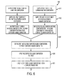
- FIG. 6 shows another exemplary method of making a roll of a media feeding assembly, according to various embodiments of the present teachings.
- FIG. 7 shows the effect of adding carbon nanotubes on the feed roll wear, in accordance with various embodiments of the present teachings.
- FIGS. 1 and 2 schematically illustrate exemplary media feeding assemblies 100, 200 in accordance with various embodiments of the present teachings.
- the media feeding assemblies 100, 200 can include a first drive roll configuration 110, 210 having a first nip 115, 215 disposed along an axis of a media feed path 130, 230 and a second drive roll configuration 120, 220 having a second nip 125, 225 disposed at a distance from the first drive roll configuration 110, 210.
- the first drive roll configuration 110 can include one or more rolls, such as for example, a feed roll, 112, a retard roll 114, and a nudger roll 140, as shown in FIG. 1 .
- the first drive roll configuration 210 can include a D shaped feed roll 211 and a retard pad 213 as shown in FIG. 2 .
- the second drive roll configuration 120, 220 can have one or more rolls, such as, for example, take away rolls 122, 124, 222, 224.
- one or more rolls 112, 114, 122, 124, 140, 211, 213, 222, 224 of the first 110, 210 and the second 120, 220 drive roll configurations can include a composite rubber tire 104', 104", 104"', 204 disposed over a roll core 102', 102", 102"', 202, as shown in FIGS. 1 and 2 .
- FIG. 1 FIG. 1
- FIG. 3 shows a cross section of an exemplary roll 312 of the first 110, 210 and the second 120, 220 drive roll configurations of the media feeding assemblies 100, 200
- the exemplary roll 312 can include a composite rubber tire 304 disposed over a roll core 302; the composite rubber tire 304 can include a plurality of soluble carbon nanotubes 303 dispersed in a first elastomeric rubber 305 to provide an increased wear resistance without a significant increase in hardness.
- FIG. 4 shows a cross section of another exemplary roll 412 of the first 110, 210 and the second 120, 220 drive roll configurations of the media feeding assemblies 100, 200.
- the exemplary roll 412 can include a second elastomeric rubber 407 disposed over a roll core 402 and a composite rubber tire 404 disposed over the second elastomeric rubber 407.
- the composite rubber tire 404 can include a plurality of soluble carbon nanotubes 403 dispersed in the first elastomeric rubber 405.
- the plurality of soluble carbon nanotubes 303, 403 dispersed in the first elastomeric rubber 305, 405 can provide at least about 10% reduction in wear without a significant increase in hardness.
- the plurality of soluble carbon nanotubes 303, 403 dispersed in the first elastomeric rubber 305, 405 can provide at least about 15% reduction in wear without a significant increase in hardness.
- wear refers to a change in a diameter of the rubber tire of the one or more rolls of the first and the second drive roll configurations per media fed due to abrasion between the tire and the media during use.
- the composite rubber tire 304, 404 can have a thickness in the range of about 100 ⁇ m to about 5000 ⁇ m and in other cases from about 1000 ⁇ m to about 2000 ⁇ m.
- the second elastomeric rubber 407 can have a thickness in the range of about 500 ⁇ m to about 5000 ⁇ m and in other embodiments from about 1000 ⁇ m to about 2000 ⁇ m.
- the roll 312, 412 can include any suitable first 305, 405 and the second 407 elastomeric rubber such as, for example, polyurethane, silicone, ethylene propylene diene M-class rubber, butyl rubber and any combination of these materials.
- the plurality of carbon nanotubes 303, 403 can be present in the first elastomeric rubber 305, 405 in an amount ranging from about 0.1 weight % to about 10 weight % of the total weight of the carbon nanotubes 303, 403 and the first elastomeric rubber 305, 405, and in some cases from about 0.1 weight % to about 5 weight % of the total weight of the carbon nanotubes 303, 403 and the first elastomeric rubber 305, 405.
- soluble carbon nanotubes refer to those carbon nanotubes that have been modified to make them more compatible with the first elastomeric rubber 305 or a solvent. Furthermore, the use of soluble carbon nanotubes improves their dispersion and the composite rubber tire's mechanical properties. Also, as used herein, the phrase “soluble carbon nanotubes are substantially uniformly dispersed in the composite rubber composition” refers that the majority of the soluble carbon nanotubes are individually dispersed in the composite rubber composition without any significant agglomeration. There are several approaches to modify carbon nanotubes to solubilize them or make them more compatible with an elastomeric rubber or a solvent. One approach is to covalently form a chemical bond to the carbon nanotube.
- This approach essentially creates defects on the carbon nanotube and very often destroys desired properties.
- Another approach is to use surfactants such as sodium dodecyl sulfate and elastomeric rubbers.
- Yet another approach is to solubilize carbon nanotubes by wrapping a molecular or polymeric chain onto a carbon nanotube. Examples of these soluble carbon nanotubes can be found in NanoSolve® products (Zyvex Performance Materials, Columbus, OH), or DNA as used by DuPont (Wilmington, DE).
- solubilization In the case of solubilization achieved by wrapping a molecular or polymeric chain, such as, for example, an elastomeric rubber onto the carbon nanotube, the solubilization enhances solubility in a solvent and dispersity in the elastomeric rubber. Although such an approach may perturb the electronic property of the carbon nanotube, it represents a good compromise. Chen et al. in Journal of American Chemical Society, 124, 9034-9035, 2002 , describe a method of forming a soluble carbon nanotube complex via ⁇ - ⁇ interaction by reacting carbon nanotubes with poly(aryleneethynylene) in chloroform.
- solubilization can be achieved by complexation between the carbon nanotube and the elastomeric rubber, without functionalizing the carbon nanotube with a functional group.
- any suitable method can be used to solubilize carbon nanotubes.
- Carbon nanotubes can be synthesized by any suitable method, including, but not limited to, arc discharge or laser ablation of graphite, chemical vapor deposition (CVD), and frame synthesis technique.
- the carbon nanotube can have just one wall, characterized as a single walled carbon nanotube, it can have two walls, characterized as a double walled carbon nanotube, or can be a multi-walled carbon nanotube.
- the purity, chirality, length, defect rate, etc. can vary. Very often, after the carbon nanotube synthesis, there can occur a mixture of tubes with a distribution of all of the above, some long, some short.
- carbon nanotubes will be metallic and some will be semiconducting.
- Single wall carbon nanotubes can be about 1 nm in diameter whereas multi-wall carbon nanotubes can measure several tens nm in diameter, and both are far thinner than their predecessors, which are called carbon fibers. It will be appreciated that differences between carbon nanotube and carbon nano fiber is decreasing with the rapid advances in the field.
- carbon nanotubes can include ones that are not exactly shaped like a tube, such as, for example, a carbon nanohorn (a horn-shaped carbon nanotube whose diameter continuously increases from one end toward the other end) which is a variant of a single-wall carbon nanotube; a carbon nanocoil (a coil-shaped carbon nanotube forming a spiral when viewed in entirety); a carbon nanobead (a spherical bead made of amorphous carbon or the like with its center pierced by a tube); a cup-stacked nanotube; and a carbon nanotube with its outer periphery covered with a carbon nanohorn or amorphous carbon.
- a carbon nanohorn a horn-shaped carbon nanotube whose diameter continuously increases from one end toward the other end
- a carbon nanocoil a coil-shaped carbon nanotube forming a spiral when viewed in entirety
- a carbon nanobead a spherical bead made of amorphous carbon or the like with its center pierce
- carbon nanotubes can include ones that contain some substances inside, such as: a metal-containing nanotube which is a carbon nanotube containing metal or the like; and a peapod nanotube which is a carbon nanotube containing a fullerene or a metal-containing fullerene.
- carbon nanotubes of any form including common carbon nanotubes, variants of the common carbon nanotubes, and carbon nanotubes with various modifications. Therefore, the concept of "carbon nanotube” in the present teachings encompasses all of the above and “soluble carbon nanotubes” can include one or more of the above carbon nanotubes.
- a printing apparatus including at least one of the media feeding assemblies shown in FIGS. 1 and 2 .
- the method 500 can include a step 561 of providing a soluble carbon nanotube composition and a step 562 of providing a first elastomeric rubber composition.
- the method 500 can also include a step 563 of mixing the soluble carbon nanotube composition with first elastomeric rubber composition to form a composite rubber composition, such that the soluble carbon nanotubes are substantially uniformly dispersed in the composite rubber composition.
- the method 500 can further include a step 564 of applying the composite rubber composition to a mold, followed by a step 565 of curing the composite rubber composition to form a composite rubber tire, such that the substantially uniformly dispersed soluble carbon nanotubes in the composite rubber provide an increased wear resistance without a significant increase in hardness.
- a roll core metal can then be inserted into a core of the composite rubber tire.
- the composite rubber tire can include one or more of a plurality of soluble single wall carbon nanotubes, a plurality of soluble double wall carbon nanotubes, and a plurality of soluble multi-wall carbon nanotubes substantially uniformly dispersed in at least one of polyurethane, silicone, ethylene propylene diene M-class rubber, butyl rubber, and any combination of these materials.
- the step 564 of applying the composite rubber composition to a mold can include applying the composite rubber composition over a roll core using a molding technique such as, for example, injection molding and compression molding and the step 565 of curing the composite rubber composition can include curing the composite rubber composition to form a composite rubber tire over the roll core.
- the step 564 of applying the composite rubber composition over a roll core can include applying a second elastomeric rubber composition to a mold and applying the composite rubber composition over the second elastomeric rubber composition. In some embodiments, the step 564 of applying the composite rubber composition over a roll core can include applying a second elastomeric rubber composition to a mold, curing the second elastomeric rubber composition to form a second elastomeric rubber tire and applying the composite rubber composition over the second elastomeric rubber tire.
- FIG. 6 shows another method 600 of making a roll of a media feeding assembly in accordance with various embodiments.
- the method 600 can include a step 661 of providing a first soluble carbon nanotube composition and a second soluble carbon nanotube composition.
- the second soluble carbon nanotube composition can differ from the first soluble carbon nanotubes in at least one of composition and concentration.
- the second soluble carbon nanotubes can be the same as the first soluble carbon nanotubes.
- the method 600 can include a step 662 of providing two components: a first component and a second component of a first elastomeric rubber composition.
- the step 662 of providing the first component of the first elastomeric rubber composition can include providing one or more of isocyanate, diorganopolysiloxane, ethylene, propylene, and isobutylene.
- the step 662 of providing the second component of the first elastomeric rubber composition can include providing one or more of polyol, diorganosiloxane, diene, and isoprene.
- the method 600 can also include a step 663 of mixing the first soluble carbon nanotube composition with the first component of the first elastomeric rubber composition to form a first composite rubber composition, mixing the second soluble carbon nanotube composition with the second component of the first elastomeric rubber composition to form a second composite rubber composition, and mixing the first composite rubber composition with the second composite rubber composition to form a composite rubber composition, wherein the first and the second soluble carbon nanotubes are substantially uniformly dispersed in the composite rubber composition.
- the method 600 can include a step 663 of mixing at least one of the first and the second soluble carbon nanotube composition with at least one of the first component or the second component of the first elastomeric rubber composition.
- the method 600 can also include a step 664 of applying the composite rubber composition to a mold and a step 665 of curing the composite rubber composition to form a composite rubber tire.
- the method 500, 600 of making a roll of a media feeding assembly can be extended to multi-component first elastomeric rubber composition, wherein one or more soluble carbon nanotube composition can be mixed with one or multiple components of the first elastomeric rubber composition.
- FIG. 7 shows the effect of adding the soluble carbon nanotubes to a feed roll sample including polyurethane tire.
- Three feed rolls having polyurethane tires were made, with one as a baseline sample with 0 weight % of soluble carbon nanotubes (NanoSolve® from Zyvex Performance Materials, Columbus, OH) and two with composite polyurethane tires having about 0.375 weight % and about 0.75 weight % of soluble carbon nanotubes (NanoSolve® from Zyvex Performance Materials, Columbus, OH) substantially uniformly dispersed in polyurethane.
- the baseline sample had an accelerated wear rate of 2.71E-5 tire diameter loss per sheet fed.
Landscapes
- Engineering & Computer Science (AREA)
- Mechanical Engineering (AREA)
- Compositions Of Macromolecular Compounds (AREA)
- Sheets, Magazines, And Separation Thereof (AREA)
- Delivering By Means Of Belts And Rollers (AREA)
- Moulds For Moulding Plastics Or The Like (AREA)
Abstract
Description
- The present invention relates to a media feeding assembly and, more particularly, to methods of making rolls of a media feeding assembly.
- Elastomeric rubbers such as, urethane, silicone, and ethylene propylene diene M-class rubber are typically used to mold tires for various rolls (e.g., nudger roll, feed roll, retard roll, take away roll) of a media feed assembly. Tire life is defined by the smallest number of sheets fed before either: 1) the tire to media coefficient of friction (Cof) drops below a minimum value required to acquire and feed a sheet of media resulting in mis-feeds or 2) abrasion between the tire and media reduces the tire diameter to a minimum diameter or causes the tire to not run true and exceeds a maximum runout. Small diameter tires can allow the media to interfere with mechanical components in the feed head while run out skews the media's lead edge during the acquisition and feed cycles. Significant development work is required to find the correct elastomer with properties that balance tire coefficient of friction versus the abrasion resistance to achieve maximum effective roll life.
- Accordingly, there is a need to overcome these and other problems of prior art to provide rolls of media feeding assembly with improved wear resistance and methods of making them.
- In accordance with various embodiments, there is a media feeding assembly including a first drive roll configuration having a first nip disposed along an axis of a media feed path, the first drive roll configuration including one or more rolls. The media feeding assembly can also include a second drive roll configuration having a second nip disposed at a distance from the first drive roll pair, the second drive roll configuration including one or more rolls, wherein the one or more rolls of the first and the second drive roll configurations can include a composite rubber tire over a roll core, the composite rubber tire including a plurality of soluble carbon nanotubes dispersed in a first elastomeric rubber to provide at least about 10 % decrease in wear.
- According to various embodiments, there is a method of making a roll of a media feeding assembly. The method can include providing a soluble carbon nanotube composition, providing a first elastomeric rubber composition, and mixing the soluble carbon nanotube composition with the first elastomeric rubber composition to form a composite rubber composition, such that the soluble carbon nanotubes are substantially uniformly dispersed in the composite rubber composition.
The method can also include applying the composite rubber composition to a mold and curing the composite rubber composition to form a composite rubber tire, such that the substantially uniformly dispersed soluble carbon nanotubes in the composite rubber tire provide at least about 10 % decrease in wear. - Additional advantages of the embodiments will be set forth in part in the description which follows, and in part will be obvious from the description, or may be learned by practice of the invention. The advantages will be realized and attained by means of the elements and combinations particularly pointed out in the appended claims.
- It is to be understood that both the foregoing general description and the following detailed description are exemplary and explanatory only and are not restrictive of the invention, as claimed.
- The accompanying drawings, which are incorporated in and constitute a part of this specification, illustrate embodiments of the invention and together with the description, serve to explain the principles of the invention.
-
FIG. 1 schematically illustrates a media feeding assembly, according to various embodiments of the present teachings. -
FIG. 2 schematically illustrates another exemplary media feeding assembly, according to various embodiments of the present teachings. -
FIG. 3 schematically illustrates a cross section of an exemplary roll of the media feeding assembly shown inFIGS. 1 and 2 , according to various embodiments of the present teachings. -
FIG. 4 schematically illustrates a cross section of another exemplary roll of the media feeding assembly shown inFIGS. 1 and 2 , according to various embodiments of the present teachings. -
FIG. 5 shows an exemplary method of making a roll of a media feeding assembly, according to various embodiments of the present teachings. -
FIG. 6 shows another exemplary method of making a roll of a media feeding assembly, according to various embodiments of the present teachings. -
FIG. 7 shows the effect of adding carbon nanotubes on the feed roll wear, in accordance with various embodiments of the present teachings. - Reference will now be made in detail to the present embodiments, examples of which are illustrated in the accompanying drawings. Wherever possible, the same reference numbers will be used throughout the drawings to refer to the same or like parts.
-
FIGS. 1 and 2 schematically illustrate exemplarymedia feeding assemblies media feeding assemblies drive roll configuration first nip media feed path drive roll configuration second nip drive roll configuration drive roll configuration 110 can include one or more rolls, such as for example, a feed roll, 112, aretard roll 114, and anudger roll 140, as shown inFIG. 1 . In other embodiments, the firstdrive roll configuration 210 can include a D shapedfeed roll 211 and aretard pad 213 as shown inFIG. 2 . In various embodiments, the seconddrive roll configuration rolls - In various embodiments, one or
more rolls composite rubber tire 104', 104", 104"', 204 disposed over aroll core 102', 102", 102"', 202, as shown inFIGS. 1 and 2 .FIG. 3 shows a cross section of an exemplary roll 312 of the first 110, 210 and the second 120, 220 drive roll configurations of themedia feeding assemblies composite rubber tire 304 disposed over aroll core 302; thecomposite rubber tire 304 can include a plurality ofsoluble carbon nanotubes 303 dispersed in a firstelastomeric rubber 305 to provide an increased wear resistance without a significant increase in hardness.FIG. 4 shows a cross section of anotherexemplary roll 412 of the first 110, 210 and the second 120, 220 drive roll configurations of themedia feeding assemblies exemplary roll 412 can include a secondelastomeric rubber 407 disposed over aroll core 402 and acomposite rubber tire 404 disposed over the secondelastomeric rubber 407. In various embodiments, thecomposite rubber tire 404 can include a plurality ofsoluble carbon nanotubes 403 dispersed in the firstelastomeric rubber 405. In some embodiments, the plurality ofsoluble carbon nanotubes elastomeric rubber soluble carbon nanotubes elastomeric rubber composite rubber tire elastomeric rubber 407 can have a thickness in the range of about 500 µm to about 5000 µm and in other embodiments from about 1000 µm to about 2000 µm. - The
roll 312, 412 can include any suitable first 305, 405 and the second 407 elastomeric rubber such as, for example, polyurethane, silicone, ethylene propylene diene M-class rubber, butyl rubber and any combination of these materials. Furthermore, the plurality ofcarbon nanotubes elastomeric rubber carbon nanotubes elastomeric rubber carbon nanotubes elastomeric rubber - As used herein, the term "soluble carbon nanotubes" refer to those carbon nanotubes that have been modified to make them more compatible with the first
elastomeric rubber 305 or a solvent. Furthermore, the use of soluble carbon nanotubes improves their dispersion and the composite rubber tire's mechanical properties. Also, as used herein, the phrase "soluble carbon nanotubes are substantially uniformly dispersed in the composite rubber composition" refers that the majority of the soluble carbon nanotubes are individually dispersed in the composite rubber composition without any significant agglomeration. There are several approaches to modify carbon nanotubes to solubilize them or make them more compatible with an elastomeric rubber or a solvent. One approach is to covalently form a chemical bond to the carbon nanotube. This approach essentially creates defects on the carbon nanotube and very often destroys desired properties. Another approach is to use surfactants such as sodium dodecyl sulfate and elastomeric rubbers. Yet another approach is to solubilize carbon nanotubes by wrapping a molecular or polymeric chain onto a carbon nanotube. Examples of these soluble carbon nanotubes can be found in NanoSolve® products (Zyvex Performance Materials, Columbus, OH), or DNA as used by DuPont (Wilmington, DE). In the case of solubilization achieved by wrapping a molecular or polymeric chain, such as, for example, an elastomeric rubber onto the carbon nanotube, the solubilization enhances solubility in a solvent and dispersity in the elastomeric rubber. Although such an approach may perturb the electronic property of the carbon nanotube, it represents a good compromise. Chen et al. in Journal of American Chemical Society, 124, 9034-9035, 2002, describe a method of forming a soluble carbon nanotube complex via π-π interaction by reacting carbon nanotubes with poly(aryleneethynylene) in chloroform. Through π-π interactions, the aromatic elastomeric rubber chains interact with the carbon nanotubes to de-bundle the carbon nanotubes. This process thus enables the resulting solublized carbon nanotubes to form a good dispersion in a solvent as well as in any polymer or a base elastomeric rubber. In some embodiments, solubilization can be achieved by complexation between the carbon nanotube and the elastomeric rubber, without functionalizing the carbon nanotube with a functional group. However, any suitable method can be used to solubilize carbon nanotubes. - Carbon nanotubes can be synthesized by any suitable method, including, but not limited to, arc discharge or laser ablation of graphite, chemical vapor deposition (CVD), and frame synthesis technique. Depending on the method of synthesis, reaction conditions, temperature, and many other parameters, the carbon nanotube can have just one wall, characterized as a single walled carbon nanotube, it can have two walls, characterized as a double walled carbon nanotube, or can be a multi-walled carbon nanotube. The purity, chirality, length, defect rate, etc. can vary. Very often, after the carbon nanotube synthesis, there can occur a mixture of tubes with a distribution of all of the above, some long, some short. Some of the carbon nanotubes will be metallic and some will be semiconducting. Single wall carbon nanotubes can be about 1 nm in diameter whereas multi-wall carbon nanotubes can measure several tens nm in diameter, and both are far thinner than their predecessors, which are called carbon fibers. It will be appreciated that differences between carbon nanotube and carbon nano fiber is decreasing with the rapid advances in the field.
- Furthermore, carbon nanotubes can include ones that are not exactly shaped like a tube, such as, for example, a carbon nanohorn (a horn-shaped carbon nanotube whose diameter continuously increases from one end toward the other end) which is a variant of a single-wall carbon nanotube; a carbon nanocoil (a coil-shaped carbon nanotube forming a spiral when viewed in entirety); a carbon nanobead (a spherical bead made of amorphous carbon or the like with its center pierced by a tube); a cup-stacked nanotube; and a carbon nanotube with its outer periphery covered with a carbon nanohorn or amorphous carbon.
- Additionally, carbon nanotubes can include ones that contain some substances inside, such as: a metal-containing nanotube which is a carbon nanotube containing metal or the like; and a peapod nanotube which is a carbon nanotube containing a fullerene or a metal-containing fullerene.
- As described above, in the present teachings, it is possible to employ carbon nanotubes of any form, including common carbon nanotubes, variants of the common carbon nanotubes, and carbon nanotubes with various modifications. Therefore, the concept of "carbon nanotube" in the present teachings encompasses all of the above and "soluble carbon nanotubes" can include one or more of the above carbon nanotubes.
- In accordance with various embodiments, there is a printing apparatus including at least one of the media feeding assemblies shown in
FIGS. 1 and 2 . - In accordance with various embodiments, there is a
method 500 of making a roll of a media feeding assembly, as shown inFIG. 5 . Themethod 500 can include astep 561 of providing a soluble carbon nanotube composition and astep 562 of providing a first elastomeric rubber composition. Themethod 500 can also include astep 563 of mixing the soluble carbon nanotube composition with first elastomeric rubber composition to form a composite rubber composition, such that the soluble carbon nanotubes are substantially uniformly dispersed in the composite rubber composition. Themethod 500 can further include astep 564 of applying the composite rubber composition to a mold, followed by astep 565 of curing the composite rubber composition to form a composite rubber tire, such that the substantially uniformly dispersed soluble carbon nanotubes in the composite rubber provide an increased wear resistance without a significant increase in hardness. A roll core metal can then be inserted into a core of the composite rubber tire. In various embodiments, the composite rubber tire can include one or more of a plurality of soluble single wall carbon nanotubes, a plurality of soluble double wall carbon nanotubes, and a plurality of soluble multi-wall carbon nanotubes substantially uniformly dispersed in at least one of polyurethane, silicone, ethylene propylene diene M-class rubber, butyl rubber, and any combination of these materials. In some embodiments, thestep 564 of applying the composite rubber composition to a mold can include applying the composite rubber composition over a roll core using a molding technique such as, for example, injection molding and compression molding and thestep 565 of curing the composite rubber composition can include curing the composite rubber composition to form a composite rubber tire over the roll core. In various embodiments, thestep 564 of applying the composite rubber composition over a roll core can include applying a second elastomeric rubber composition to a mold and applying the composite rubber composition over the second elastomeric rubber composition. In some embodiments, thestep 564 of applying the composite rubber composition over a roll core can include applying a second elastomeric rubber composition to a mold, curing the second elastomeric rubber composition to form a second elastomeric rubber tire and applying the composite rubber composition over the second elastomeric rubber tire. -
FIG. 6 shows anothermethod 600 of making a roll of a media feeding assembly in accordance with various embodiments. Themethod 600 can include astep 661 of providing a first soluble carbon nanotube composition and a second soluble carbon nanotube composition. In some embodiments, the second soluble carbon nanotube composition can differ from the first soluble carbon nanotubes in at least one of composition and concentration. In other embodiments, the second soluble carbon nanotubes can be the same as the first soluble carbon nanotubes. Themethod 600 can include astep 662 of providing two components: a first component and a second component of a first elastomeric rubber composition. In some embodiments, thestep 662 of providing the first component of the first elastomeric rubber composition can include providing one or more of isocyanate, diorganopolysiloxane, ethylene, propylene, and isobutylene. In other embodiments, thestep 662 of providing the second component of the first elastomeric rubber composition can include providing one or more of polyol, diorganosiloxane, diene, and isoprene. Themethod 600 can also include astep 663 of mixing the first soluble carbon nanotube composition with the first component of the first elastomeric rubber composition to form a first composite rubber composition, mixing the second soluble carbon nanotube composition with the second component of the first elastomeric rubber composition to form a second composite rubber composition, and mixing the first composite rubber composition with the second composite rubber composition to form a composite rubber composition, wherein the first and the second soluble carbon nanotubes are substantially uniformly dispersed in the composite rubber composition. In some embodiments, themethod 600 can include astep 663 of mixing at least one of the first and the second soluble carbon nanotube composition with at least one of the first component or the second component of the first elastomeric rubber composition. Themethod 600 can also include astep 664 of applying the composite rubber composition to a mold and astep 665 of curing the composite rubber composition to form a composite rubber tire. In various embodiments, themethod -
FIG. 7 shows the effect of adding the soluble carbon nanotubes to a feed roll sample including polyurethane tire. Three feed rolls having polyurethane tires were made, with one as a baseline sample with 0 weight % of soluble carbon nanotubes (NanoSolve® from Zyvex Performance Materials, Columbus, OH) and two with composite polyurethane tires having about 0.375 weight % and about 0.75 weight % of soluble carbon nanotubes (NanoSolve® from Zyvex Performance Materials, Columbus, OH) substantially uniformly dispersed in polyurethane. The baseline sample had an accelerated wear rate of 2.71E-5 tire diameter loss per sheet fed. Adding about 0.375% and about 0.75% by weight of the soluble carbon nanotubes reduced the wear rate to about 2.21E-5 diameter loss per sheet fed (about 18% reduction) and about 1.89E-5 diameter loss per sheet fed (about 30% reduction) respectively over the baseline feed roll polyurethane sample. The results shown inFIG. 7 indicate that the incorporation of soluble carbon nanotubes can greatly improve wear resistance. - While the invention has been illustrated respect to one or more implementations, alterations and/or modifications can be made to the illustrated examples without departing from the spirit and scope of the appended claims. In addition, while a particular feature of the invention may have been disclosed with respect to only one of several implementations, such feature may be combined with one or more other features of the other implementations as may be desired and advantageous for any given or particular function
- Other embodiments of the invention will be apparent to those skilled in the art from consideration of the specification and practice of the invention disclosed herein. It is intended that the specification and examples be considered as exemplary only, with the scope of the invention being indicated by the following claims.
Claims (15)
- A media feeding assembly comprising:a first drive roll configuration having a first nip disposed along an axis of a media feed path, the first drive roll configuration comprising one or more rolls; anda second drive roll configuration having a second nip disposed at a distance from the first drive roll pair, the second drive roll configuration comprising one or more rolls,wherein the one or more rolls of the first and the second drive roll configurations comprise a composite rubber tire over a roll core, the composite rubber tire comprising a plurality of soluble carbon nanotubes dispersed in a first elastomeric rubber in an amount to provide at least about 10 % decrease in wear.
- The media feeding assembly of claim 1, wherein the one or more rolls of the first and the second drive roll configurations further comprises:a second elastomeric rubber disposed over the roll core; anda composite rubber disposed over the second elastomeric rubber, the composite rubber comprising a plurality of soluble carbon nanotubes dispersed in a first elastomeric rubber; preferablythe first and the second elastomeric rubber is selected from a group consisting of polyurethane, silicone, ethylene propylene diene M-class rubber, butyl rubber, and mixtures thereof.
- The media feeding assembly of claim 1, wherein the plurality of soluble carbon nanotubes are present in an amount ranging from about 0.1 weight % to about 10 weight % of the total weight of the carbon nanotubes and the first elastomeric rubber.
- The media feeding assembly of claim 1, wherein the first drive roll configuration comprises:- a feed roll, a retard roll, and a nudger roll; or- D shaped feed roll and a retard pad.
- A printing apparatus comprising the media feeding assembly of claim 1.
- A method of making a roll of a media feeding assembly, the method comprising:providing a soluble carbon nanotube composition;providing a first elastomeric rubber composition;mixing the soluble carbon nanotube composition with the first elastomeric rubber composition to form a composite rubber composition, such that the soluble carbon nanotubes are substantially uniformly dispersed in the composite rubber composition;applying the composite rubber composition to a mold; andcuring the composite rubber composition to form a composite rubber tire, such that the substantially uniformly dispersed soluble carbon nanotubes in the composite rubber tire provide at least about 10 % decrease in wear.
- The method of making a roll of a media feeding assembly according to claim 6, wherein the step of applying the composite rubber composition to a mold comprises:- applying the composite rubber composition over a roll core using a technique selected from the group consisting of compression molding and injection molding, and curing the composite rubber composition to form a composite rubber tire over the roll core; or- applying a second elastomeric rubber composition to a mold, and applying the composite rubber composition over the second elastomeric rubber composition.
- The method of making a roll of a media feeding assembly according to claim 6, wherein the step of providing a soluble carbon nanotubes comprises:providing a first soluble carbon nanotube composition; andproviding a second soluble carbon nanotube composition, wherein the second soluble carbon nanotubes differs from the first soluble carbon nanotubes in at least one of composition and concentration.
- The method of making a roll of a media feeding assembly according to claim 6, wherein the step of providing a first elastomeric rubber composition comprises:providing a first component of a first elastomeric rubber composition; andproviding a second component of the first elastomeric rubber composition.
- The method of making a roll of a media feeding assembly according to claim 9, wherein the step of mixing the soluble carbon nanotubes with the first elastomeric rubber composition to form a composite rubber composition comprises mixing the soluble carbon nanotubes with at least one of the first component and the second component of the first elastomeric rubber composition.
- The method of making a roll of a media feeding assembly according to claim 9, wherein the step of mixing the soluble carbon nanotube composition with the first elastomeric rubber composition to form a composite rubber composition comprises:mixing a first soluble carbon nanotube composition with the first component of the first elastomeric rubber composition to form a first composite rubber composition, wherein the first soluble carbon nanotubes are substantially uniformly dispersed in the first composite rubber composition;mixing a second soluble carbon nanotube composition with the second component of the first elastomeric rubber composition to form a second composite rubber composition, wherein the second soluble carbon nanotubes are substantially uniformly dispersed in the second composite rubber composition;mixing the first composite rubber composition with the second composite rubber composition to form a composite rubber composition, wherein the first and the second soluble carbon nanotubes are substantially uniformly dispersed in the composite rubber composition.
- The method of making a roll of a media feeding assembly according to claim 6, wherein the composite rubber tire comprises carbon nanotubes in an amount ranging from about 0.1 weight % to about 10 weight % of the total weight of the composite rubber.
- The method of making a roll of a media feeding assembly according to claim 6, wherein the first elastomeric rubber composition is selected from a group consisting of polyurethane, silicone, ethylene propylene diene M-class rubber, butyl, and combinations thereof.
- The method of making a roll of a media feeding assembly according to claim 6, wherein the first component of the first elastomeric rubber composition is selected from a group consisting of isocyanate, diorganopolysiloxane, ethylene, propylene, and isobutylene.
- The method of making a roll of a media feeding assembly according to claim 6, wherein the second component of the first elastomeric rubber composition is selected from a group consisting of polyol, diorganosiloxane, diene, and isoprene.
Applications Claiming Priority (1)
| Application Number | Priority Date | Filing Date | Title |
|---|---|---|---|
| US12/423,107 US8852064B2 (en) | 2009-04-14 | 2009-04-14 | Reduced feed roll wear using carbon nanotube additives in rubbers |
Publications (3)
| Publication Number | Publication Date |
|---|---|
| EP2241522A2 true EP2241522A2 (en) | 2010-10-20 |
| EP2241522A3 EP2241522A3 (en) | 2013-03-06 |
| EP2241522B1 EP2241522B1 (en) | 2016-10-12 |
Family
ID=42352061
Family Applications (1)
| Application Number | Title | Priority Date | Filing Date |
|---|---|---|---|
| EP10158710.3A Not-in-force EP2241522B1 (en) | 2009-04-14 | 2010-03-31 | Reduced feed roll wear using carbon nanotube additives in rubbers |
Country Status (3)
| Country | Link |
|---|---|
| US (1) | US8852064B2 (en) |
| EP (1) | EP2241522B1 (en) |
| JP (1) | JP5749896B2 (en) |
Cited By (1)
| Publication number | Priority date | Publication date | Assignee | Title |
|---|---|---|---|---|
| WO2012080159A1 (en) * | 2010-12-14 | 2012-06-21 | Styron Europe Gmbh | Improved elastomer formulations |
Families Citing this family (1)
| Publication number | Priority date | Publication date | Assignee | Title |
|---|---|---|---|---|
| CN113666146B (en) * | 2021-08-23 | 2022-05-24 | 常州汉威信科技股份有限公司 | Four-roller type paper separating device |
Family Cites Families (14)
| Publication number | Priority date | Publication date | Assignee | Title |
|---|---|---|---|---|
| JP2617661B2 (en) * | 1992-09-30 | 1997-06-04 | 富士システム機器株式会社 | Cut sheet separation feeding device |
| DE60037981T2 (en) * | 1999-04-06 | 2009-02-05 | Seiko Epson Corp. | Ink jet recording apparatus |
| JP2002278217A (en) * | 2001-03-19 | 2002-09-27 | Ricoh Co Ltd | Contact charging device, contact charging method, image forming apparatus and process cartridge |
| KR100592527B1 (en) | 2002-01-17 | 2006-06-23 | (주)케이에이치 케미컬 | Rubber composition comprising carbon nanotubes as reinforcing agent and method for producing same |
| JP4002450B2 (en) | 2002-02-26 | 2007-10-31 | 住友ゴム工業株式会社 | Rubber roller and manufacturing method thereof |
| JP4227786B2 (en) | 2002-09-10 | 2009-02-18 | 住友ゴム工業株式会社 | Conductive roller and method of manufacturing the conductive roller |
| US6923533B2 (en) | 2002-12-09 | 2005-08-02 | Xerox Corporation | Phase change ink imaging component with nano-size filler |
| JP4285299B2 (en) | 2004-03-30 | 2009-06-24 | 住友ゴム工業株式会社 | Paper feed roller |
| JP2005314019A (en) | 2004-04-27 | 2005-11-10 | Fuiisa Kk | Sheet-fed material transport roller and equipment using the same |
| US8075863B2 (en) * | 2004-05-26 | 2011-12-13 | Massachusetts Institute Of Technology | Methods and devices for growth and/or assembly of nanostructures |
| JP4578924B2 (en) | 2004-10-08 | 2010-11-10 | グローリー株式会社 | Banknote storage device |
| US7387297B2 (en) * | 2005-06-24 | 2008-06-17 | Xerox Corporation | Printing system sheet feeder using rear and front nudger rolls |
| US8017863B2 (en) * | 2005-11-02 | 2011-09-13 | The Regents Of The University Of Michigan | Polymer wrapped carbon nanotube near-infrared photoactive devices |
| JP4593445B2 (en) | 2005-11-15 | 2010-12-08 | 住友ゴム工業株式会社 | Paper feed roller |
-
2009
- 2009-04-14 US US12/423,107 patent/US8852064B2/en not_active Expired - Fee Related
-
2010
- 2010-03-31 EP EP10158710.3A patent/EP2241522B1/en not_active Not-in-force
- 2010-04-14 JP JP2010092824A patent/JP5749896B2/en not_active Expired - Fee Related
Non-Patent Citations (1)
| Title |
|---|
| CHEN ET AL., JOURNAL OF AMERICAN CHEMICAL SOCIETY, vol. 124, 2002, pages 9034 - 9035 |
Cited By (7)
| Publication number | Priority date | Publication date | Assignee | Title |
|---|---|---|---|---|
| WO2012080159A1 (en) * | 2010-12-14 | 2012-06-21 | Styron Europe Gmbh | Improved elastomer formulations |
| WO2012080160A1 (en) * | 2010-12-14 | 2012-06-21 | Styron Europe Gmbh | Improved elastomer formulations |
| CN103313935A (en) * | 2010-12-14 | 2013-09-18 | 思迪隆欧洲有限公司 | Improved elastomer formulations |
| US9353240B2 (en) | 2010-12-14 | 2016-05-31 | Molecular Rebar Design, Llc | Elastomer formulations comprising discrete carbon nanotube fibers |
| US9422413B1 (en) | 2010-12-14 | 2016-08-23 | Molecular Rebar Design, Llc | Elastomer formulations comprising discrete carbon nanotube fibers |
| US9493626B1 (en) | 2010-12-14 | 2016-11-15 | Molecular Rebar Design, Llc | Dispersions comprising discrete carbon nanotube fibers |
| US9636649B2 (en) | 2010-12-14 | 2017-05-02 | Molecular Rebar Design, Llc | Dispersions comprising discrete carbon nanotube fibers |
Also Published As
| Publication number | Publication date |
|---|---|
| EP2241522A3 (en) | 2013-03-06 |
| US20100258238A1 (en) | 2010-10-14 |
| EP2241522B1 (en) | 2016-10-12 |
| JP5749896B2 (en) | 2015-07-15 |
| US8852064B2 (en) | 2014-10-07 |
| JP2010247991A (en) | 2010-11-04 |
Similar Documents
| Publication | Publication Date | Title |
|---|---|---|
| US8329293B2 (en) | Carbon fiber composite material | |
| Graupner | Raman spectroscopy of covalently functionalized single‐wall carbon nanotubes | |
| Mu et al. | An in situ Raman spectroscopy study of stress transfer between carbon nanotubes and polymer | |
| US8513348B2 (en) | Carbon nanofibers, method of producing carbon nanofibers, carbon fiber composite material using carbon nanofibers, and method of producing the carbon fiber composite material | |
| EP1857495B1 (en) | Carbon fiber composite resin material and method of producing the same | |
| EP3262105B1 (en) | Method for making carbon nanostructure preblends | |
| EP1790685B1 (en) | Thermoplastic resin composition comprising carbon nanofibers | |
| TW202146560A (en) | Elastomer compositions with carbon nanostructure filler | |
| EP2228406A1 (en) | Improved mechanical properties of epoxy filled with functionalized carbon nanotubes | |
| EP1927625B1 (en) | Carbon fiber composite material and method of producing the same | |
| CN108779337B (en) | Thermoplastic resin composition and method for producing thermoplastic resin composition | |
| KR20130125381A (en) | Improved Elastomer Blend | |
| EP1939249A1 (en) | Thermoplastic elastomer composition | |
| EP1792935B1 (en) | Thermosetting resin composition and method of producing the same | |
| Jung et al. | The influence of N-doping types for carbon nanotube reinforced epoxy composites: A combined experimental study and molecular dynamics simulation | |
| EP2241522B1 (en) | Reduced feed roll wear using carbon nanotube additives in rubbers | |
| EP3392301A1 (en) | Novel nanocarbon composite | |
| Tran et al. | Manufacturing polymer/carbon nanotube composite using a novel direct process | |
| JP2005314019A (en) | Sheet-fed material transport roller and equipment using the same | |
| Kolodziej et al. | Investigations on natural rubber filled with multiwall carbon nanotubes | |
| Rhue et al. | Length reduction kinetics of multiwalled carbon nanotubes correlated to planetary ball mill impact energy | |
| KR102150277B1 (en) | A rubber composition for racing tire | |
| JPS62299412A (en) | Radial tire | |
| Lederer et al. | Characterization of Physical Properties for Multi-Scale Polymer Composites Under Various Processing Conditions | |
| JP2002146191A (en) | Silicone rubber composition for paper feed roll and paper feed roll |
Legal Events
| Date | Code | Title | Description |
|---|---|---|---|
| PUAI | Public reference made under article 153(3) epc to a published international application that has entered the european phase |
Free format text: ORIGINAL CODE: 0009012 |
|
| AK | Designated contracting states |
Kind code of ref document: A2 Designated state(s): AT BE BG CH CY CZ DE DK EE ES FI FR GB GR HR HU IE IS IT LI LT LU LV MC MK MT NL NO PL PT RO SE SI SK SM TR |
|
| AX | Request for extension of the european patent |
Extension state: AL BA ME RS |
|
| PUAL | Search report despatched |
Free format text: ORIGINAL CODE: 0009013 |
|
| AK | Designated contracting states |
Kind code of ref document: A3 Designated state(s): AT BE BG CH CY CZ DE DK EE ES FI FR GB GR HR HU IE IS IT LI LT LU LV MC MK MT NL NO PL PT RO SE SI SK SM TR |
|
| AX | Request for extension of the european patent |
Extension state: AL BA ME RS |
|
| RIC1 | Information provided on ipc code assigned before grant |
Ipc: B65H 27/00 20060101ALI20130128BHEP Ipc: B65H 3/06 20060101AFI20130128BHEP |
|
| 17P | Request for examination filed |
Effective date: 20130906 |
|
| RBV | Designated contracting states (corrected) |
Designated state(s): AT BE BG CH CY CZ DE DK EE ES FI FR GB GR HR HU IE IS IT LI LT LU LV MC MK MT NL NO PL PT RO SE SI SK SM TR |
|
| 17Q | First examination report despatched |
Effective date: 20150219 |
|
| GRAP | Despatch of communication of intention to grant a patent |
Free format text: ORIGINAL CODE: EPIDOSNIGR1 |
|
| INTG | Intention to grant announced |
Effective date: 20160616 |
|
| GRAS | Grant fee paid |
Free format text: ORIGINAL CODE: EPIDOSNIGR3 |
|
| GRAA | (expected) grant |
Free format text: ORIGINAL CODE: 0009210 |
|
| AK | Designated contracting states |
Kind code of ref document: B1 Designated state(s): AT BE BG CH CY CZ DE DK EE ES FI FR GB GR HR HU IE IS IT LI LT LU LV MC MK MT NL NO PL PT RO SE SI SK SM TR |
|
| REG | Reference to a national code |
Ref country code: GB Ref legal event code: FG4D |
|
| REG | Reference to a national code |
Ref country code: CH Ref legal event code: EP |
|
| REG | Reference to a national code |
Ref country code: AT Ref legal event code: REF Ref document number: 836295 Country of ref document: AT Kind code of ref document: T Effective date: 20161015 |
|
| REG | Reference to a national code |
Ref country code: IE Ref legal event code: FG4D |
|
| REG | Reference to a national code |
Ref country code: DE Ref legal event code: R096 Ref document number: 602010037084 Country of ref document: DE |
|
| REG | Reference to a national code |
Ref country code: LT Ref legal event code: MG4D |
|
| REG | Reference to a national code |
Ref country code: NL Ref legal event code: MP Effective date: 20161012 |
|
| REG | Reference to a national code |
Ref country code: FR Ref legal event code: PLFP Year of fee payment: 8 |
|
| PG25 | Lapsed in a contracting state [announced via postgrant information from national office to epo] |
Ref country code: LV Free format text: LAPSE BECAUSE OF FAILURE TO SUBMIT A TRANSLATION OF THE DESCRIPTION OR TO PAY THE FEE WITHIN THE PRESCRIBED TIME-LIMIT Effective date: 20161012 |
|
| REG | Reference to a national code |
Ref country code: AT Ref legal event code: MK05 Ref document number: 836295 Country of ref document: AT Kind code of ref document: T Effective date: 20161012 |
|
| PG25 | Lapsed in a contracting state [announced via postgrant information from national office to epo] |
Ref country code: SE Free format text: LAPSE BECAUSE OF FAILURE TO SUBMIT A TRANSLATION OF THE DESCRIPTION OR TO PAY THE FEE WITHIN THE PRESCRIBED TIME-LIMIT Effective date: 20161012 Ref country code: GR Free format text: LAPSE BECAUSE OF FAILURE TO SUBMIT A TRANSLATION OF THE DESCRIPTION OR TO PAY THE FEE WITHIN THE PRESCRIBED TIME-LIMIT Effective date: 20170113 Ref country code: NO Free format text: LAPSE BECAUSE OF FAILURE TO SUBMIT A TRANSLATION OF THE DESCRIPTION OR TO PAY THE FEE WITHIN THE PRESCRIBED TIME-LIMIT Effective date: 20170112 Ref country code: LT Free format text: LAPSE BECAUSE OF FAILURE TO SUBMIT A TRANSLATION OF THE DESCRIPTION OR TO PAY THE FEE WITHIN THE PRESCRIBED TIME-LIMIT Effective date: 20161012 |
|
| PG25 | Lapsed in a contracting state [announced via postgrant information from national office to epo] |
Ref country code: NL Free format text: LAPSE BECAUSE OF FAILURE TO SUBMIT A TRANSLATION OF THE DESCRIPTION OR TO PAY THE FEE WITHIN THE PRESCRIBED TIME-LIMIT Effective date: 20161012 Ref country code: IS Free format text: LAPSE BECAUSE OF FAILURE TO SUBMIT A TRANSLATION OF THE DESCRIPTION OR TO PAY THE FEE WITHIN THE PRESCRIBED TIME-LIMIT Effective date: 20170212 Ref country code: PL Free format text: LAPSE BECAUSE OF FAILURE TO SUBMIT A TRANSLATION OF THE DESCRIPTION OR TO PAY THE FEE WITHIN THE PRESCRIBED TIME-LIMIT Effective date: 20161012 Ref country code: HR Free format text: LAPSE BECAUSE OF FAILURE TO SUBMIT A TRANSLATION OF THE DESCRIPTION OR TO PAY THE FEE WITHIN THE PRESCRIBED TIME-LIMIT Effective date: 20161012 Ref country code: AT Free format text: LAPSE BECAUSE OF FAILURE TO SUBMIT A TRANSLATION OF THE DESCRIPTION OR TO PAY THE FEE WITHIN THE PRESCRIBED TIME-LIMIT Effective date: 20161012 Ref country code: FI Free format text: LAPSE BECAUSE OF FAILURE TO SUBMIT A TRANSLATION OF THE DESCRIPTION OR TO PAY THE FEE WITHIN THE PRESCRIBED TIME-LIMIT Effective date: 20161012 Ref country code: ES Free format text: LAPSE BECAUSE OF FAILURE TO SUBMIT A TRANSLATION OF THE DESCRIPTION OR TO PAY THE FEE WITHIN THE PRESCRIBED TIME-LIMIT Effective date: 20161012 Ref country code: BE Free format text: LAPSE BECAUSE OF FAILURE TO SUBMIT A TRANSLATION OF THE DESCRIPTION OR TO PAY THE FEE WITHIN THE PRESCRIBED TIME-LIMIT Effective date: 20161012 Ref country code: PT Free format text: LAPSE BECAUSE OF FAILURE TO SUBMIT A TRANSLATION OF THE DESCRIPTION OR TO PAY THE FEE WITHIN THE PRESCRIBED TIME-LIMIT Effective date: 20170213 |
|
| REG | Reference to a national code |
Ref country code: DE Ref legal event code: R097 Ref document number: 602010037084 Country of ref document: DE |
|
| PG25 | Lapsed in a contracting state [announced via postgrant information from national office to epo] |
Ref country code: CZ Free format text: LAPSE BECAUSE OF FAILURE TO SUBMIT A TRANSLATION OF THE DESCRIPTION OR TO PAY THE FEE WITHIN THE PRESCRIBED TIME-LIMIT Effective date: 20161012 Ref country code: SK Free format text: LAPSE BECAUSE OF FAILURE TO SUBMIT A TRANSLATION OF THE DESCRIPTION OR TO PAY THE FEE WITHIN THE PRESCRIBED TIME-LIMIT Effective date: 20161012 Ref country code: DK Free format text: LAPSE BECAUSE OF FAILURE TO SUBMIT A TRANSLATION OF THE DESCRIPTION OR TO PAY THE FEE WITHIN THE PRESCRIBED TIME-LIMIT Effective date: 20161012 Ref country code: RO Free format text: LAPSE BECAUSE OF FAILURE TO SUBMIT A TRANSLATION OF THE DESCRIPTION OR TO PAY THE FEE WITHIN THE PRESCRIBED TIME-LIMIT Effective date: 20161012 Ref country code: EE Free format text: LAPSE BECAUSE OF FAILURE TO SUBMIT A TRANSLATION OF THE DESCRIPTION OR TO PAY THE FEE WITHIN THE PRESCRIBED TIME-LIMIT Effective date: 20161012 |
|
| PLBE | No opposition filed within time limit |
Free format text: ORIGINAL CODE: 0009261 |
|
| STAA | Information on the status of an ep patent application or granted ep patent |
Free format text: STATUS: NO OPPOSITION FILED WITHIN TIME LIMIT |
|
| PG25 | Lapsed in a contracting state [announced via postgrant information from national office to epo] |
Ref country code: SM Free format text: LAPSE BECAUSE OF FAILURE TO SUBMIT A TRANSLATION OF THE DESCRIPTION OR TO PAY THE FEE WITHIN THE PRESCRIBED TIME-LIMIT Effective date: 20161012 Ref country code: BG Free format text: LAPSE BECAUSE OF FAILURE TO SUBMIT A TRANSLATION OF THE DESCRIPTION OR TO PAY THE FEE WITHIN THE PRESCRIBED TIME-LIMIT Effective date: 20170112 Ref country code: IT Free format text: LAPSE BECAUSE OF FAILURE TO SUBMIT A TRANSLATION OF THE DESCRIPTION OR TO PAY THE FEE WITHIN THE PRESCRIBED TIME-LIMIT Effective date: 20161012 |
|
| 26N | No opposition filed |
Effective date: 20170713 |
|
| REG | Reference to a national code |
Ref country code: CH Ref legal event code: PL |
|
| PG25 | Lapsed in a contracting state [announced via postgrant information from national office to epo] |
Ref country code: SI Free format text: LAPSE BECAUSE OF FAILURE TO SUBMIT A TRANSLATION OF THE DESCRIPTION OR TO PAY THE FEE WITHIN THE PRESCRIBED TIME-LIMIT Effective date: 20161012 Ref country code: MC Free format text: LAPSE BECAUSE OF FAILURE TO SUBMIT A TRANSLATION OF THE DESCRIPTION OR TO PAY THE FEE WITHIN THE PRESCRIBED TIME-LIMIT Effective date: 20161012 |
|
| REG | Reference to a national code |
Ref country code: IE Ref legal event code: MM4A |
|
| PG25 | Lapsed in a contracting state [announced via postgrant information from national office to epo] |
Ref country code: LU Free format text: LAPSE BECAUSE OF NON-PAYMENT OF DUE FEES Effective date: 20170331 |
|
| REG | Reference to a national code |
Ref country code: FR Ref legal event code: PLFP Year of fee payment: 9 |
|
| PG25 | Lapsed in a contracting state [announced via postgrant information from national office to epo] |
Ref country code: LI Free format text: LAPSE BECAUSE OF NON-PAYMENT OF DUE FEES Effective date: 20170331 Ref country code: CH Free format text: LAPSE BECAUSE OF NON-PAYMENT OF DUE FEES Effective date: 20170331 Ref country code: IE Free format text: LAPSE BECAUSE OF NON-PAYMENT OF DUE FEES Effective date: 20170331 |
|
| PG25 | Lapsed in a contracting state [announced via postgrant information from national office to epo] |
Ref country code: MT Free format text: LAPSE BECAUSE OF NON-PAYMENT OF DUE FEES Effective date: 20170331 |
|
| PG25 | Lapsed in a contracting state [announced via postgrant information from national office to epo] |
Ref country code: HU Free format text: LAPSE BECAUSE OF FAILURE TO SUBMIT A TRANSLATION OF THE DESCRIPTION OR TO PAY THE FEE WITHIN THE PRESCRIBED TIME-LIMIT; INVALID AB INITIO Effective date: 20100331 |
|
| PG25 | Lapsed in a contracting state [announced via postgrant information from national office to epo] |
Ref country code: CY Free format text: LAPSE BECAUSE OF NON-PAYMENT OF DUE FEES Effective date: 20161012 |
|
| PG25 | Lapsed in a contracting state [announced via postgrant information from national office to epo] |
Ref country code: MK Free format text: LAPSE BECAUSE OF FAILURE TO SUBMIT A TRANSLATION OF THE DESCRIPTION OR TO PAY THE FEE WITHIN THE PRESCRIBED TIME-LIMIT Effective date: 20161012 |
|
| PG25 | Lapsed in a contracting state [announced via postgrant information from national office to epo] |
Ref country code: TR Free format text: LAPSE BECAUSE OF FAILURE TO SUBMIT A TRANSLATION OF THE DESCRIPTION OR TO PAY THE FEE WITHIN THE PRESCRIBED TIME-LIMIT Effective date: 20161012 |
|
| PGFP | Annual fee paid to national office [announced via postgrant information from national office to epo] |
Ref country code: DE Payment date: 20200218 Year of fee payment: 11 Ref country code: GB Payment date: 20200221 Year of fee payment: 11 |
|
| PGFP | Annual fee paid to national office [announced via postgrant information from national office to epo] |
Ref country code: FR Payment date: 20200220 Year of fee payment: 11 |
|
| REG | Reference to a national code |
Ref country code: DE Ref legal event code: R119 Ref document number: 602010037084 Country of ref document: DE |
|
| GBPC | Gb: european patent ceased through non-payment of renewal fee |
Effective date: 20210331 |
|
| PG25 | Lapsed in a contracting state [announced via postgrant information from national office to epo] |
Ref country code: DE Free format text: LAPSE BECAUSE OF NON-PAYMENT OF DUE FEES Effective date: 20211001 Ref country code: FR Free format text: LAPSE BECAUSE OF NON-PAYMENT OF DUE FEES Effective date: 20210331 Ref country code: GB Free format text: LAPSE BECAUSE OF NON-PAYMENT OF DUE FEES Effective date: 20210331 |