EP2241230A1 - Used capsule or pod receptacle for liquid food or beverage machines - Google Patents
Used capsule or pod receptacle for liquid food or beverage machines Download PDFInfo
- Publication number
- EP2241230A1 EP2241230A1 EP10168049A EP10168049A EP2241230A1 EP 2241230 A1 EP2241230 A1 EP 2241230A1 EP 10168049 A EP10168049 A EP 10168049A EP 10168049 A EP10168049 A EP 10168049A EP 2241230 A1 EP2241230 A1 EP 2241230A1
- Authority
- EP
- European Patent Office
- Prior art keywords
- receptacle
- seat
- cavity
- pods
- capsules
- Prior art date
- Legal status (The legal status is an assumption and is not a legal conclusion. Google has not performed a legal analysis and makes no representation as to the accuracy of the status listed.)
- Granted
Links
- 239000002775 capsule Substances 0.000 title claims abstract description 120
- 235000013361 beverage Nutrition 0.000 title claims abstract description 54
- 235000021056 liquid food Nutrition 0.000 title claims abstract description 37
- 238000003860 storage Methods 0.000 claims abstract description 52
- 238000002360 preparation method Methods 0.000 claims abstract description 36
- 238000003780 insertion Methods 0.000 claims abstract description 23
- 230000037431 insertion Effects 0.000 claims abstract description 23
- 235000012041 food component Nutrition 0.000 claims abstract description 3
- 239000005417 food ingredient Substances 0.000 claims abstract description 3
- 239000007788 liquid Substances 0.000 claims description 16
- 239000004615 ingredient Substances 0.000 claims description 12
- 230000002829 reductive effect Effects 0.000 claims description 4
- 238000000605 extraction Methods 0.000 description 8
- 235000016213 coffee Nutrition 0.000 description 5
- 235000013353 coffee beverage Nutrition 0.000 description 5
- 230000002401 inhibitory effect Effects 0.000 description 5
- XLYOFNOQVPJJNP-UHFFFAOYSA-N water Substances O XLYOFNOQVPJJNP-UHFFFAOYSA-N 0.000 description 5
- 239000000243 solution Substances 0.000 description 4
- 244000269722 Thea sinensis Species 0.000 description 3
- 238000004140 cleaning Methods 0.000 description 3
- 239000012530 fluid Substances 0.000 description 3
- 235000013336 milk Nutrition 0.000 description 3
- 239000008267 milk Substances 0.000 description 3
- 210000004080 milk Anatomy 0.000 description 3
- 230000002093 peripheral effect Effects 0.000 description 3
- 244000299461 Theobroma cacao Species 0.000 description 2
- XAGFODPZIPBFFR-UHFFFAOYSA-N aluminium Chemical compound [Al] XAGFODPZIPBFFR-UHFFFAOYSA-N 0.000 description 2
- 229910052782 aluminium Inorganic materials 0.000 description 2
- 239000004411 aluminium Substances 0.000 description 2
- 230000002452 interceptive effect Effects 0.000 description 2
- 230000003287 optical effect Effects 0.000 description 2
- 230000000284 resting effect Effects 0.000 description 2
- 235000014347 soups Nutrition 0.000 description 2
- 239000002699 waste material Substances 0.000 description 2
- 240000007154 Coffea arabica Species 0.000 description 1
- 235000005764 Theobroma cacao ssp. cacao Nutrition 0.000 description 1
- 235000005767 Theobroma cacao ssp. sphaerocarpum Nutrition 0.000 description 1
- 235000001046 cacaotero Nutrition 0.000 description 1
- 230000015556 catabolic process Effects 0.000 description 1
- 238000006243 chemical reaction Methods 0.000 description 1
- 235000019219 chocolate Nutrition 0.000 description 1
- 238000006731 degradation reaction Methods 0.000 description 1
- 238000005429 filling process Methods 0.000 description 1
- 230000005484 gravity Effects 0.000 description 1
- 238000010438 heat treatment Methods 0.000 description 1
- 238000002347 injection Methods 0.000 description 1
- 239000007924 injection Substances 0.000 description 1
- 210000000629 knee joint Anatomy 0.000 description 1
- 238000007726 management method Methods 0.000 description 1
- 238000000034 method Methods 0.000 description 1
- 239000000843 powder Substances 0.000 description 1
- 230000002028 premature Effects 0.000 description 1
- 238000000926 separation method Methods 0.000 description 1
- 239000000126 substance Substances 0.000 description 1
- 235000013616 tea Nutrition 0.000 description 1
- 230000000007 visual effect Effects 0.000 description 1
Images


Classifications
-
- A—HUMAN NECESSITIES
- A47—FURNITURE; DOMESTIC ARTICLES OR APPLIANCES; COFFEE MILLS; SPICE MILLS; SUCTION CLEANERS IN GENERAL
- A47J—KITCHEN EQUIPMENT; COFFEE MILLS; SPICE MILLS; APPARATUS FOR MAKING BEVERAGES
- A47J31/00—Apparatus for making beverages
- A47J31/44—Parts or details or accessories of beverage-making apparatus
-
- A—HUMAN NECESSITIES
- A47—FURNITURE; DOMESTIC ARTICLES OR APPLIANCES; COFFEE MILLS; SPICE MILLS; SUCTION CLEANERS IN GENERAL
- A47J—KITCHEN EQUIPMENT; COFFEE MILLS; SPICE MILLS; APPARATUS FOR MAKING BEVERAGES
- A47J31/00—Apparatus for making beverages
- A47J31/24—Coffee-making apparatus in which hot water is passed through the filter under pressure, i.e. in which the coffee grounds are extracted under pressure
- A47J31/34—Coffee-making apparatus in which hot water is passed through the filter under pressure, i.e. in which the coffee grounds are extracted under pressure with hot water under liquid pressure
- A47J31/36—Coffee-making apparatus in which hot water is passed through the filter under pressure, i.e. in which the coffee grounds are extracted under pressure with hot water under liquid pressure with mechanical pressure-producing means
- A47J31/3604—Coffee-making apparatus in which hot water is passed through the filter under pressure, i.e. in which the coffee grounds are extracted under pressure with hot water under liquid pressure with mechanical pressure-producing means with a mechanism arranged to move the brewing chamber between loading, infusing and ejecting stations
- A47J31/3609—Loose coffee being employed
- A47J31/3619—Means to remove coffee after brewing
-
- A—HUMAN NECESSITIES
- A47—FURNITURE; DOMESTIC ARTICLES OR APPLIANCES; COFFEE MILLS; SPICE MILLS; SUCTION CLEANERS IN GENERAL
- A47J—KITCHEN EQUIPMENT; COFFEE MILLS; SPICE MILLS; APPARATUS FOR MAKING BEVERAGES
- A47J31/00—Apparatus for making beverages
- A47J31/24—Coffee-making apparatus in which hot water is passed through the filter under pressure, i.e. in which the coffee grounds are extracted under pressure
- A47J31/34—Coffee-making apparatus in which hot water is passed through the filter under pressure, i.e. in which the coffee grounds are extracted under pressure with hot water under liquid pressure
- A47J31/36—Coffee-making apparatus in which hot water is passed through the filter under pressure, i.e. in which the coffee grounds are extracted under pressure with hot water under liquid pressure with mechanical pressure-producing means
- A47J31/3604—Coffee-making apparatus in which hot water is passed through the filter under pressure, i.e. in which the coffee grounds are extracted under pressure with hot water under liquid pressure with mechanical pressure-producing means with a mechanism arranged to move the brewing chamber between loading, infusing and ejecting stations
- A47J31/3623—Cartridges being employed
- A47J31/3638—Means to eject the cartridge after brewing
Definitions
- the field of the invention pertains to used capsule or pod receptacles of machines for preparing liquid food or beverages from an ingredient of the liquid food or beverage supplied within a capsule or pod to the machine.
- Liquid food or beverage preparation machines are becoming very popular whether at home or in offices. For instance, there are machines for the preparation of beverages such as coffee, tea, soup or other similar beverages, in which at least one ingredient of the desired beverage, for example ground coffee, is supplied within a capsule or pod into a capsule or pod extraction chamber of the machine.
- beverages such as coffee, tea, soup or other similar beverages
- at least one ingredient of the desired beverage for example ground coffee
- capsules or pods such as plastic and/or aluminium-based capsules or pods for the preparation of beverages has many advantages.
- Capsules or pods, in particular aluminium-based capsules or pods are hermetic or gas tight and thus can protect the beverage ingredient effectively during an extended period of time against the environment such as air, humidity or light, before use of the ingredient.
- capsules and pods prevent premature degradation of the ingredient.
- capsules or pods of a beverage ingredient are easy to handle, hygienic, and their use involves less cleaning of the beverage preparation machine, in particular no significant part of the machine's extraction chamber comes into contact with the beverage ingredient contained in the capsule or pod during the extraction process.
- Capsules or pods are usually inserted individually into the machine's extraction chamber, manually or automatically from a capsule or pod stack. Hot or cold water is then passed through the capsule or pod for brewing or otherwise extracting the ingredient(s) contained within the capsule or pod and form the desired beverage.
- the prepared beverage is supplied via an outlet of the machine into a cup, mug or other receptacle to the user.
- Used capsules or pods may either be removed individually from the liquid food or beverage preparation machine after each preparation cycle or they may be collected in a machine's used capsule or pod receptacle for instance as mentioned in EP 1 731 065 .
- the capsule or pod receptacle is located underneath the capsule or pod chamber so that the capsules or pods may fall by gravity into the receptacle upon extraction. In the latter case, the receptacle has to be emptied by the user when full.
- the receptacle may be a drawer-type removable receptacle located in a seat of the beverage preparation machine typically under the extraction chamber.
- the used capsule or pod receptacle may be slid in and out of the machine's housing.
- a problem may arise with such capsule or pod receptacles, in particular in conjunction with rigid capsules or pods, when used capsules or pods accumulate in the receptacle to form a heap of capsules or pods whose top extends above the receptacle in such a manner to come into conflict with the housing when the receptacle is slid out of the machine's housing for emptying.
- a solution to avoid the jamming of the receptacle by used capsules or pods is to provide an optical level detector for measuring the level of capsules or pods in the used capsule or pod receptacle and inviting the user to empty the receptacle when the level of capsules or pods comes close to the level of the machine's housing.
- Another solution involves counting the number of capsule or pod extractions after emptying the receptacle and inviting the user to empty the receptacle after a predetermined number of capsules or pods has been collected, an excess of which may possibly cause jamming.
- a drawback with the level detector system involves the use of expensive electronic detectors, in particular optical detectors. Furthermore, since the accumulated capsules or pods naturally form a heap in the receptacle a waste of space is usually also involved around this heap.
- a drawback of the capsule or pod counting system lies in the fact that, in order to avoid jamming at all time, it is necessary to set a maximum number of collectible capsules or pods in the receptacle that will often lead to a poor filling of the receptacle at the time when the user will be invited to re-empty the receptacle and to an even greater waste of space around the heap of collected capsules or pods in the receptacle than with the above described level detector.
- the invention thus relates to a machine for preparing a liquid food or beverage from a pre-portioned beverage or food ingredient in a capsule or pod.
- the machine is a coffee, tea or soup preparation machine.
- the machine is arranged for preparing within a liquid food or beverage module a beverage or liquid food by passing hot or cold water or another liquid through a capsule or pod containing an ingredient of the beverage or liquid food to be prepared, such as ground coffee or tea or chocolate or cacao or milk powder.
- the preparation machine comprises: a liquid food or beverage preparation unit arranged to receive capsules or pods for use and evacuate capsules or pods upon use; a housing having an opening leading into a seat to which capsules or pods are evacuated from the preparation unit; and a receptacle having a cavity forming a storage space for collecting capsules or pods evacuated to the seat into the receptacle to a level of fill.
- the receptacle is insertable into the seat for collecting capsules or pods and is removable from the seat for emptying the collected capsules or pods.
- the preparation machine further comprises means to inhibit jamming of the receptacle at removal from the seat when the level of fill in the receptacle extends above the opening of the housing.
- the jamming inhibiting means are so arranged that the collected capsules or pods in the receptacle are inhibited from interfering with the housing at removal of the receptacle through the housing's opening.
- the jamming inhibiting means may be arranged to: lower the level of fill of collected capsules or pods in the receptacle for its removal.
- the machine is associated with a mechanical means arranged to redistribute an accumulated heap of capsules or pods in the receptacle to improve occupation of the storage space with capsules or pods.
- Such means may include a vibration or shaking means of the receptacle or other means that lowers the level of such a heap.
- Other means arranged to lower the level of fill of collected capsules or pods in the receptacle for removal thereof are discussed below.
- the jamming inhibiting means may be arranged to: displace the receptacle with its level of fill of collected capsules or pods.
- the receptacle is associated with an elevator means that raises the receptacle in the seat into its operative position to collect capsules or pods and that lowers the receptacle in the seat for removal thereof through the opening of the housing so that capsules or pods that could accumulate to a level above the receptacle's mouth in the operative position of the receptacle would be lowered relative to an upper part of the housing opening in a removal step of the receptacle.
- the jamming inhibiting means are arranged to reorient, in particular within the seat, the receptacle so that the level of fill is lowered relative to an upper par of the opening of the housing.
- reorientations of the receptacle are disclosed in application EP 08155753.0 of which priority is claimed for the present application and the content of which is hereby incorporated by way of reference.
- the preparation machine comprises: a liquid food or beverage preparation unit arranged to receive capsules or pods for use and evacuate capsules or pods upon use; a seat to which capsules or pods are evacuated from the preparation unit; and a receptacle having a cavity forming a storage space for collecting capsules or pods evacuated to the seat.
- the receptacle is insertable into the seat for collecting capsules or pods and is removable from the seat for emptying the collected capsules or pods.
- the preparation machine further comprises a means for reducing the storage space of the receptacle at insertion into the seat and for increasing the storage space of the receptacle at removal from the seat.
- used capsules or pods that drop into the collection receptacle via the receptacle's mouth tend to accumulate in the form of a heap in the receptacle.
- This heap of capsules or pods may rise up to a level that exceeds to level of the receptacle's mouth.
- a state of the art capsule or pod collection arrangement typically a drawer-type receptacle
- pulling the receptacle out from the cavity will be inhibited by the top of the heap of capsules extending above the receptacle's opening, which top will collide with the fixed outer wall of the device's housing that more or less matches the upper edge of the front wall of the movable capsule receptacle.
- the receptacle will be jammed by the capsules in the cavity and the user will be faced with the problem of unjamming the receptacle.
- the present invention provides a solution to this problem by reducing the capsule or pod storage space in the receptacle during collection of capsules or pods, and by increasing the available storage space when the receptacle is removed from the preparation machine for emptying the collected capsules or pods.
- the seat comprises or is assembled to a body that is arranged to:
- this body will be moulded or cast with the seat or will be mounted on an anchorage part integral with the seat.
- the receptacle has a wall delimiting the cavity, the wall having a through-opening for allowing the passage of the body into the cavity.
- the body can be associated with: a rear face or rear end of the seat and may be arranged to extend via the through-opening of a rear wall of the receptacle; and/or a side face or side of the seat and is arranged to extend via the through-opening of a sidewall of the receptacle.
- the seat may include an elevator platform that is arranged to raise the receptacle within the seat against a counter-body of the seat or lower it therefrom.
- the counter-body may be arranged to: enter the receptacle's mouth to reduce the receptacle's storage space when the receptacle is in its operative position to collect capsules or pods; and exit the receptacle's mouth to increase the receptacle's storage space when the receptacle is lowered from its operative position and removed from the seat.
- a counter-body that is lowered and raised into the receptacle's mouth to reduce and increase the receptacle's storage space.
- the elevator-type movements of the platform or of the counter-body can be manually or motor-driven.
- the receptacle comprises a plurality of walls delimiting the cavity, at least one of which being relatively movable in the receptacle to increase and reduce the storage space at removal and insertion of the receptacle, respectively.
- the cavity is delimited by two cooperating shells that are movable relatively to one another.
- the cooperating shells as well as the receptacle and the seat can be relatively and respectively movable to one another along substantially parallel directions.
- at least one relatively movable wall, in particular a shell, of the receptacle is movable in a sliding or telescopic movement in the receptacle.
- the receptacle can have a bottom with at least one arrangement, such as one or more through-openings or drain-holes, for the evacuation of liquid.
- the receptacle can be located on a reservoir for collecting liquid from the receptacle.
- the receptacle and the reservoir may be insertable into and removable from the seat en bloc.
- Another aspect of the invention concerns a receptacle having a cavity forming a storage space for collecting capsules or pods.
- a receptacle can be insertable and removable from a seat of a machine for preparing liquid food or beverage that is arranged to evacuate ingredient capsules or pods to such a seat upon use, as described above.
- This receptacle comprises means associated with its cavity for reducing the storage space at insertion into such a seat and for increasing the storage space at removal from such a seat.
- Such a receptacle may include any feature or combination of features disclosed in the relation with the receptacle of the liquid food or beverage preparation machine described above.
- FIG. 1 shows a liquid food or beverage machine according to the invention.
- the machine has a liquid food or beverage unit 2 in a housing 9.
- Unit 2 is arranged for receiving an ingredient capsule or pod and feeding a liquid to the capsule or pod.
- Unit 2 is mounted on a platform 1 and extends along a lateral side 1' thereof.
- a beverage outlet 95 for dispensing beverage from unit 2 extends through a front face 94 of housing 9.
- Unit 2 includes a brewing module (not shown) that comprises an opening and closure handle 11 and means for holding a substance-containing capsule or pod, e.g., a coffee capsule, and liquid food or beverage delivery means such as a liquid food or beverage duct 95.
- the holding means typically comprises a capsule holder and a brewing cage, a fluid injection system for injecting water in the capsule and a closure device such as a lever and a knee joint mechanism.
- Suitable extraction modules are described in EP 1 859 713 . Further possible features of unit 2 are discussed in greater details in co-pending application EP07123009 , the content of which is hereby incorporated by way of reference.
- housing 9 houses within a receptacle seat a used capsule or pod receptacle 30 that has a front face 31 and that is removably inserted under the brewing unit and outlet 95, in accordance with the invention.
- Receptacle 30 and its seat in housing 9 will be discussed in greater details in relation with Figs 2 to 8b .
- Platform 1 has at least the minimal functions as to the fluid and power management, which is supplying the liquid food or beverage unit 2 with electrical power and with water from water tank 7 attached to the base platform externally to housing 9 and adjacent to the rear wall of housing 9.
- a master switch 3 is mounted on platform 1 for shutting on and off the machine.
- Two user-buttons 12, typically for selecting a small or large quantity of liquid food or beverage to be prepared, are located above unit 2.
- Upper face 34 of platform 1 has means in the form of a STRIXTM connector (not shown) for connecting a milk frothing device 8.
- STRIXTM connector for the beverage or liquid food machine and frothing device 8 are for example disclosed in greater detail in WO 03/075629 , WO 2008/046837 and in PCT/EP08/056349 which are hereby incorporated by way of reference.
- Upper face 34 is adjacent neighbouring front face 35 that can be associated with a heating system, in particular integrated in platform 1, and that may be arranged to support one or more cups or mugs for preheating thereof prior to use.
- liquid food or beverage unit 2 generally extends upwards within housing 9 adjacent a first lateral edge 1' of platform 1.
- Frothing device 8 is generally located adjacent a second lateral edge of platform 1 opposite the first edge 1", so that housing 9 and platform 1 generally form in cross-section an L-shape that supports frothing device 8.
- the liquid food or beverage machine also includes a support device 6 for supporting mugs that is located under beverage outlet 95 and that is in the shape of a perforated plate for evacuating liquid.
- a collector 6a in the form of a shallow reservoir is located underneath support device 6 for collecting the evacuated liquid. Collector 6a does not require a high capacity for collecting liquid. Most of the time, collector 6a will only have to collect drips and spills.
- Support device 6 and collector 6a are separable en bloc from platform 1, for instance for emptying collector 6a and/or for cleaning.
- the liquid food or beverage machine has, above support device 6, a second support plate 21 for supporting recipients, such as cups, of smaller size underneath the outlet 95.
- second support plate 21 comprises a perforated plate for the evacuation of liquid, in particular to collector 6a, optionally via support device 6.
- Second support plate 21 is movable into a generally horizontal operative position between the outlet 95 and support device 6, as illustrated, and is movable into a generally upright or vertical rest position away therefrom so that a larger recipient is placeable on support device 6 under outlet 95.
- Second support plate 21 is in particular rotatable and/or slidable from its operative position into its rest position. Further details of possible features of such second support device are for example disclosed in EP 1 867 260 .
- FIG. 2 in which the same numeric references generally designate the same elements, shows another embodiment of the invention.
- the preparation machine shown in Fig. 2 has the same features as the machine of Fig. 1 except for the absence of the lateral platform extension supporting a milk frothing device.
- the preparation machine of Fig. 2 has a seat 5 for receiving a receptacle 30 having a cavity 30' that forms a storage space for collecting used capsules or pods.
- Receptacle 30 may be assembled to a cup support device 20 which includes cup support member 21 that is pivotally mounted onto a reservoir 22 supporting receptacle 30.
- Support member 21 is assembled to or integral with a stop member 24 that is rotatable with support member against a front face of reservoir 24 to stop the downward rotation of support member 21 and secure member 21 in a horizontal position.
- Receptacle 30 may have bottom part with a drain-hole so that reservoir 22 can collect liquid drained from this bottom part into reservoir 22 via the drain-hole. Cup support device 20 and receptacle 30 resting thereon may be inserted and removed en bloc from seat 5. Further details of receptacle 30 and seat 5 are discussed in relation with Figures 3a to 5b .
- collector 6a supporting support device 6 may be removably assembled via a mechanical connector 4 to platform 1.
- Figs 3a to 5a and 3b to 5b show in perspective view and cross-sectional view, respectively, different positions of receptacle 30 relative to seat 5: an inserted position ( Figs 3a and 3b ); an intermediate position ( Figs 4a and 4b ) at insertion or removal; and a removed position ( Figs 5a and 5b ).
- the capsule or pod collection arrangement of a machine includes three units, namely: a capsule or pod receptacle 30; a cup support device 20 on which receptacle 30 is mounted; and a seat 5 for housing receptacle 30 on cup support device 20.
- Seat 5 is located within housing 9 underneath the brewing unit (with handle 11) of liquid food or beverage unit 2.
- Seat 5 has a bottom 53, a rear face 51, facing side faces 51' and a front opening 5' (see Fig. 5a ) for allowing the insertion and the removal of receptacle 30 and reservoir 22.
- Cup support device 20 comprises a perforated support plate 21 that is hingedly assembled to liquid collection reservoir 22 via axis 23.
- Collection reservoir 22 has a rim that supports and holds capsule or pod receptacle 30, so that reservoir 22 and receptacle 30 can be inserted and removed from seat 5 en bloc.
- Receptacle 30 has a generally funnel-shaped bottom 35 with a through-hole 35' for evacuating liquid, in particular from capsules or pods upon use or from a cleaning or rinsing process of the preparation machine, to reservoir 22 located underneath.
- Cavity 30' of receptacle 30 is generally delimited by bottom 35, front wall 31, facing sidewalls 32 and rear wall 33.
- Receptacle 30 is so dimensioned that front wall 31 comes generally flush with front face 94 of housing 9 when receptacle 30 is in its operative position inserted in seat 5.
- Front wall 31 can be transparent or translucent to permit visual examination by a user of the level of fill of receptacle 30 with capsules or pods.
- front wall 31 may have one or more through-openings 317 for the evacuation of steam from cavity 30' of receptacle 30, in particular a series of side-by-side elongated through-openings, such as through-openings 317 extending over substantially an entire height of front wall 31.
- wall 31 may include two adjacent parallel lines 312,314 of generally vertically extending parallel and spaced apart side-by-side members 311,313.
- These two lines 312,314 of parallel upright members 311,313 can be offset so that the parallel members 311,313 of the two lines 312,314 are in a staggered arrangement, in a zigzag order, or in positions alternating on either side of a median line 316 extending between the two lines 312,314.
- the two lines 312,314 of parallel upright members 311,313 may extend between end portions 315 of sidewalls 32 of receptacle 30.
- the spaced apart upright parallel members 311,313 may delimit therebetween through-openings 317.
- through-openings 317 have a flow-through orientation that is parallel to the general direction 316 of front wall 31. Hence, steam or fluid will not be able to project in direct line from cavity 30' outside but will be diverted the staggered arrangement 311,313.
- the liquid food or beverage preparation machine further comprises a means for reducing the storage space of receptacle 30 at insertion into seat 5 and for increasing the storage space of receptacle 30 at removal from the seat 5.
- such means are provided, on the one hand, in the form of a through-opening 34 delimited by rear wall 33 or receptacle 30 and, on the other hand, by a body 52 protruding out from rear wall 51 or seat 5.
- Through-opening 34 and body 52 cooperate so that: when receptacle 30 is inserted in seat 5, body 52 extends via through-opening 34 into cavity 30' of receptacle 30 whereby the storage space of cavity 30' is reduced by the corresponding intruding volume of body 52, as illustrated in Figs 3a and 3b ; when receptacle 30 is removed from seat 5, the volume previously occupied by body 52 in cavity 30' is freed, whereby the storage space of cavity 30' is increased in the absence of body 52 in cavity 30', as illustrated in Figs 5a and 5b .
- body 52 retracts from or penetrates into cavity 30' via through-opening 34 of rear wall 33, as shown in Figs 4a and 4b .
- a user may still remove receptacle 30 from seat 5 without risk of jamming receptacle 30, as the removal operation increases the available storage space of receptacle 30.
- body 52 withdraws from cavity 30' leaving additional space therein.
- body 52 may freely enter empty cavity 30' to reduce its storage capacity for the capsule or pod filling process.
- Figs 9a and 9b in which the same numeric references generally designate the same elements, show two schematic views from above of a variation of the receptacle and seat shown in Figs 3a to 5b .
- Fig. 9a illustrates receptacle 30 in its operative position for collecting capsules or pods.
- Fig. 9b illustrates receptacle 30 in an intermediate position at removal (or insertion) into seat 5 of the preparation machine.
- seat 5 has a pair of spaced apart bodies 52',52" that are located at opposite end corners of seat 5 and that are arranged to enter laterally into cavity 30' via cut-outs or through-openings 34',34" formed at rear corners between sidewalls 32 and rear wall 33.
- through-opening 34',34" and bodies 52',52" cooperate so that: when receptacle 30 is inserted in seat 5, bodies 52',52" extend laterally via corresponding through-openings 34',34" into cavity 30' of receptacle 30 whereby the storage space of cavity 30' is reduced by the corresponding intruding volumes of bodies 52',52", as illustrated in Fig 9a ; when receptacle 30 is removed from seat 5, the volumes previously occupied by bodies 52',52" in cavity 30' are freed, whereby the storage space of cavity 30' is increased in the absence of bodies 52',52" in cavity 30', as illustrated in Fig. 9b .
- bodies 52',52" retract from or penetrate into cavity 30' via through-openings 34',34" of sidewalls 32 and rear wall.
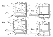
- Figs 7a and 7b schematically illustrate a further embodiment of receptacle 30 and seat 5 of a liquid food or beverage preparation machine according to the invention.
- Fig 7a illustrates receptacle 30 in its operative position in seat 5.
- Figure 7b illustrates receptacle 30 during insertion into or removal from seat 5.
- the means for reducing the storage space of receptacle 30 at insertion into seat 5 and for increasing the storage space of receptacle 30 at removal from the seat 5 include a pair of facing shells 36,37 delimiting cavity 30' of receptacle 30.
- Shells 36,37 are movable relatively to one another to increase and decrease the storage space of cavity 30'.
- shells 36,37 are in a telescopic arrangement.
- Peripheral portions 36a of walls 32 and bottom 35 of shell 36 may slide in an out from grooves 37' in corresponding peripheral portions 37a of walls 38 and bottom 39 of shell 37.
- groove 37' and/or peripheral portions 36a may incorporate an abutment or like arrangement (not shown), as known in the art.
- receptacle 30 has its shells 36,37 urged together for reducing the storage space of cavity 30', as illustrated in Fig. 7a .
- front shell 36 may first be pulled out, e.g. telescoped out, for instance by means of a handle or grip (not shown), while leaving rear shell 37 in place in seat 5 with rear walls 33,51 of receptacle 30 and seat 5 remaining together, as illustrated in Fig. 7b .
- the size of cavity 30' of receptacle 30 is correspondingly increased and capsules or pods collected therein have an increased storage space in receptacle 30.
- capsules or pods that would have been accumulated above the mouth of receptacle 30, in particular up to and into passage 55, so as to overfill receptacle 30 in its operating position are redistributed in the enlarged cavity 30' having a larger storage space.
- Such an arrangement significantly reduces the risk of clogging or jamming of capsule or pod collection receptacles at removal.
- receptacle 30 may be further pulled along the same direction to remove receptacle 30 including rear shell 37 entirely from seat 5.
- pivotable support plate 21 should be in its deployed operative horizontal position when receptacle 30 is being removed from or inserted into seat 5.
- reservoir 22 holding receptacle 30 may follow rear shell 37 and have a corresponding shape to allow relative movements in seat 5 of front shell 37 on reservoir 22.
- the receptacle and the reservoir it is of course possible to arrange the receptacle and the reservoir so that the reservoir follows the receptacle's front shell. In a second variation, it is also possible to arrange the receptacle and the reservoir so that the reservoir follows the receptacle's front shell at insertion of the receptacle into the seat and so that the reservoir follows the receptacle's rear shell at removal of the receptacle from the seat, or vice versa.
- FIGs 8a and 8b schematically illustrate a further embodiment of receptacle 30 and seat 5 of a liquid food or beverage preparation machine according to the invention.
- Figure 7a illustrates receptacle 30 during insertion into or removal from seat 5.
- Fig 7b illustrates receptacle 30 in its operative position in seat 5.
- the means for reducing the storage space of receptacle 30 at insertion into seat 5 and for increasing the storage space of receptacle 30 at removal from the seat 5 include an elevator like platform 56 and a counter-body 58 in seat 5.
- Elevator-like platform 56 is movable up and down by means of drive rod 57.
- Platform 56 is arranged to support bottom 35 of receptacle 30 and move receptacle 30 up and down between bottom 53 and top 54 of seat 5.
- seat 5 has a counter-body 58 that is arranged to reduce the storage space of cavity 30' when receptacle 30 is in its operative position to collect pods or capsules.
- receptacle 30 This operative position of receptacle 30 is illustrated in Fig. 8b .
- receptacle 30 is lifted by platform 56 against top 54 so that counter-body 58 enters into receptacle 30 via its mouth for reducing the storage space of cavity 30'.
- Capsules or pods may be evacuated from the brewing unit into cavity 30' via passage 55 in counter-body 58.
- platform 56 with receptacle 30 may be lowered as illustrated in Fig. 8a .
- the top surface of platform 56 which contacts bottom 35 of receptacle 30, comes generally flush with the top surface of support plate 21 when in its deployed horizontal operative position.
- top surfaces of platform 56 and of support plate 21 provide one substantially continuous guide surface for moving receptacle 30 in and out from seat 5.
- the upper space or cavity 30' previously occupied by counter-body 58 is freed and the capsules or pods in excess may occupy this newly freed space so as to reduce or eliminate the risk or clogging or jamming receptacle 30 when pulled out of seat 5 via opening 5'.
- the receptacle and seat schematically shown in Figs 8a and 8b are not associated with a separated reservoir for collecting liquid and the receptacle is not provide with a drain-hole for evacuating such liquid to the reservoir.
- such liquid is directly collected and accumulated on the bottom of the receptacle.
- the pivotable support plate 21 is directly pivotally mounted via axis 23 on seat 5 (or on the housing of the preparation machine).
- Support plate 21 is connected to a stop member 24 that is pivotable with support plate 21 against seat 21 (or against the housing of the preparation machine) to hold and secure support plate 21 in a substantially horizontal operative position.
- Support plate 21 may also be pivoted upwards in an upright rest position to cover opening 5'.
- the counter-body up and down in the cavity of the receptacle so as to increase and decrease its storage space, instead or moving the entire receptacle up and down by means of the platform.
- the receptacle is safely secured in its operative position within the seat and does not risk to come out or fall out inadvertently.
- FIGs 10a and 10b A further elevator-type variation is shown in Figs 10a and 10b , in which the same numeric references generally designate the same elements, where no counter-body is arranged to enter into the cavity 30' of receptacle 30.
- the jamming inhibiting means do not affect the storage space of receptacle 30.
- elevator-like platform 56 is movable up and down by means of drive rod 57.
- Platform 56 is arranged to support bottom 35 of receptacle 30 and move receptacle 30 up and down between bottom 53 and top 54 of seat 5.
- Platform 56 is arranged to hold receptacle 30 in its operative position against top 54 ( Fig. 10b ) and lower receptacle 30 for removal ( Fig. 10a ).
- receptacle 30 capsules or pods may be evacuated from the brewing unit into cavity 30' via passage 55.
- platform 56 with receptacle 30 may be lowered as illustrated in Fig. 10a . In this lower position, remaining used capsules or pods may come down from passage 55 to unclog receptacle 30, whereby receptacle 30 may be pulled out from seat 5 without having capsules or pods interfering with an upper part of opening 5' of the machine's housing.
- FIGs 11a and 11b Yet another elevator-type variation is schematically illustrated in Figs 11a and 11b , in which the same numeric references generally designate the same elements.
- bottom 35 of receptacle 30 is movable up and down within a bottom part of receptacle 30 to reduce and increase, respectively the storage space of cavity 30'.
- bottom 35 may be raised and lowered by elevator platform 56 between abutments 33' and bottom flanges 33" protruding from rear wall 33 and front wall 31 of receptacle 30.
- the movable bottom of the receptacle may include horizontally extending cam followers that protrude beyond the receptacle's sidewalls in a manner to allow vertical movements of the cam followers.
- the sidewalls of the seat have corresponding cams in which or against which the cam followers engage when the receptacle is moved horizontally into the seat, the cams being arranged so as to guide the cam followers upwards as the receptacle is introduced into the seat and downwards when the receptacle is removed from the seat.
Abstract
Description
- The field of the invention pertains to used capsule or pod receptacles of machines for preparing liquid food or beverages from an ingredient of the liquid food or beverage supplied within a capsule or pod to the machine.
- Liquid food or beverage preparation machines are becoming very popular whether at home or in offices. For instance, there are machines for the preparation of beverages such as coffee, tea, soup or other similar beverages, in which at least one ingredient of the desired beverage, for example ground coffee, is supplied within a capsule or pod into a capsule or pod extraction chamber of the machine.
- The use of capsules or pods, such as plastic and/or aluminium-based capsules or pods for the preparation of beverages has many advantages. Capsules or pods, in particular aluminium-based capsules or pods, are hermetic or gas tight and thus can protect the beverage ingredient effectively during an extended period of time against the environment such as air, humidity or light, before use of the ingredient. Thus such capsules and pods prevent premature degradation of the ingredient. Furthermore, capsules or pods of a beverage ingredient are easy to handle, hygienic, and their use involves less cleaning of the beverage preparation machine, in particular no significant part of the machine's extraction chamber comes into contact with the beverage ingredient contained in the capsule or pod during the extraction process.
- Capsules or pods are usually inserted individually into the machine's extraction chamber, manually or automatically from a capsule or pod stack. Hot or cold water is then passed through the capsule or pod for brewing or otherwise extracting the ingredient(s) contained within the capsule or pod and form the desired beverage. The prepared beverage is supplied via an outlet of the machine into a cup, mug or other receptacle to the user.
- Used capsules or pods may either be removed individually from the liquid food or beverage preparation machine after each preparation cycle or they may be collected in a machine's used capsule or pod receptacle for instance as mentioned in
EP 1 731 065 - Typically, the capsule or pod receptacle is located underneath the capsule or pod chamber so that the capsules or pods may fall by gravity into the receptacle upon extraction. In the latter case, the receptacle has to be emptied by the user when full. The receptacle may be a drawer-type removable receptacle located in a seat of the beverage preparation machine typically under the extraction chamber. The used capsule or pod receptacle may be slid in and out of the machine's housing.
- A problem may arise with such capsule or pod receptacles, in particular in conjunction with rigid capsules or pods, when used capsules or pods accumulate in the receptacle to form a heap of capsules or pods whose top extends above the receptacle in such a manner to come into conflict with the housing when the receptacle is slid out of the machine's housing for emptying.
- A solution to avoid the jamming of the receptacle by used capsules or pods is to provide an optical level detector for measuring the level of capsules or pods in the used capsule or pod receptacle and inviting the user to empty the receptacle when the level of capsules or pods comes close to the level of the machine's housing. Another solution involves counting the number of capsule or pod extractions after emptying the receptacle and inviting the user to empty the receptacle after a predetermined number of capsules or pods has been collected, an excess of which may possibly cause jamming.
- A drawback with the level detector system involves the use of expensive electronic detectors, in particular optical detectors. Furthermore, since the accumulated capsules or pods naturally form a heap in the receptacle a waste of space is usually also involved around this heap. A drawback of the capsule or pod counting system lies in the fact that, in order to avoid jamming at all time, it is necessary to set a maximum number of collectible capsules or pods in the receptacle that will often lead to a poor filling of the receptacle at the time when the user will be invited to re-empty the receptacle and to an even greater waste of space around the heap of collected capsules or pods in the receptacle than with the above described level detector.
- Hence, there is still a need to provide an inexpensive simple solution for avoiding jamming of a used capsule or pod receptacle in a liquid food or beverage machine.
- The invention thus relates to a machine for preparing a liquid food or beverage from a pre-portioned beverage or food ingredient in a capsule or pod.
- For instance, the machine is a coffee, tea or soup preparation machine. In particular, the machine is arranged for preparing within a liquid food or beverage module a beverage or liquid food by passing hot or cold water or another liquid through a capsule or pod containing an ingredient of the beverage or liquid food to be prepared, such as ground coffee or tea or chocolate or cacao or milk powder.
- In a broad aspect of the invention, the preparation machine comprises: a liquid food or beverage preparation unit arranged to receive capsules or pods for use and evacuate capsules or pods upon use; a housing having an opening leading into a seat to which capsules or pods are evacuated from the preparation unit; and a receptacle having a cavity forming a storage space for collecting capsules or pods evacuated to the seat into the receptacle to a level of fill. The receptacle is insertable into the seat for collecting capsules or pods and is removable from the seat for emptying the collected capsules or pods.
- In accordance with the invention, the preparation machine further comprises means to inhibit jamming of the receptacle at removal from the seat when the level of fill in the receptacle extends above the opening of the housing. In particular, the jamming inhibiting means are so arranged that the collected capsules or pods in the receptacle are inhibited from interfering with the housing at removal of the receptacle through the housing's opening.
- The jamming inhibiting means may be arranged to: lower the level of fill of collected capsules or pods in the receptacle for its removal. For instance, the machine is associated with a mechanical means arranged to redistribute an accumulated heap of capsules or pods in the receptacle to improve occupation of the storage space with capsules or pods. Such means may include a vibration or shaking means of the receptacle or other means that lowers the level of such a heap. Other means arranged to lower the level of fill of collected capsules or pods in the receptacle for removal thereof are discussed below.
- The jamming inhibiting means may be arranged to: displace the receptacle with its level of fill of collected capsules or pods. In one embodiment, the receptacle is associated with an elevator means that raises the receptacle in the seat into its operative position to collect capsules or pods and that lowers the receptacle in the seat for removal thereof through the opening of the housing so that capsules or pods that could accumulate to a level above the receptacle's mouth in the operative position of the receptacle would be lowered relative to an upper part of the housing opening in a removal step of the receptacle. In another embodiment, the jamming inhibiting means are arranged to reorient, in particular within the seat, the receptacle so that the level of fill is lowered relative to an upper par of the opening of the housing. Examples of such reorientations of the receptacle are disclosed in application
EP 08155753.0 - In a particular aspect of the invention, the preparation machine comprises: a liquid food or beverage preparation unit arranged to receive capsules or pods for use and evacuate capsules or pods upon use; a seat to which capsules or pods are evacuated from the preparation unit; and a receptacle having a cavity forming a storage space for collecting capsules or pods evacuated to the seat. The receptacle is insertable into the seat for collecting capsules or pods and is removable from the seat for emptying the collected capsules or pods. In accordance with the invention, the preparation machine further comprises a means for reducing the storage space of the receptacle at insertion into the seat and for increasing the storage space of the receptacle at removal from the seat.
- As mentioned above, used capsules or pods that drop into the collection receptacle via the receptacle's mouth tend to accumulate in the form of a heap in the receptacle. This heap of capsules or pods may rise up to a level that exceeds to level of the receptacle's mouth.
- If a state of the art capsule or pod collection arrangement is used, typically a drawer-type receptacle, pulling the receptacle out from the cavity will be inhibited by the top of the heap of capsules extending above the receptacle's opening, which top will collide with the fixed outer wall of the device's housing that more or less matches the upper edge of the front wall of the movable capsule receptacle. In such a situation, the receptacle will be jammed by the capsules in the cavity and the user will be faced with the problem of unjamming the receptacle.
- The present invention provides a solution to this problem by reducing the capsule or pod storage space in the receptacle during collection of capsules or pods, and by increasing the available storage space when the receptacle is removed from the preparation machine for emptying the collected capsules or pods.
- In one embodiment, the seat comprises or is assembled to a body that is arranged to:
- enter the cavity at insertion of the receptacle into the seat, whereby the storage space is reduced; and
- exit the cavity at removal of the receptacle from the seat, whereby the storage space is increased.
- Typically, this body will be moulded or cast with the seat or will be mounted on an anchorage part integral with the seat.
- For instance, the receptacle has a wall delimiting the cavity, the wall having a through-opening for allowing the passage of the body into the cavity. The body can be associated with: a rear face or rear end of the seat and may be arranged to extend via the through-opening of a rear wall of the receptacle; and/or a side face or side of the seat and is arranged to extend via the through-opening of a sidewall of the receptacle.
- It is also contemplated to provide an elevator-type system to increase and reduce the storage space of the receptacle. For example, the seat may include an elevator platform that is arranged to raise the receptacle within the seat against a counter-body of the seat or lower it therefrom. In other words, the counter-body may be arranged to: enter the receptacle's mouth to reduce the receptacle's storage space when the receptacle is in its operative position to collect capsules or pods; and exit the receptacle's mouth to increase the receptacle's storage space when the receptacle is lowered from its operative position and removed from the seat. Alternatively, it is also possible to provide a counter-body that is lowered and raised into the receptacle's mouth to reduce and increase the receptacle's storage space. The elevator-type movements of the platform or of the counter-body can be manually or motor-driven.
- In another embodiment, the receptacle comprises a plurality of walls delimiting the cavity, at least one of which being relatively movable in the receptacle to increase and reduce the storage space at removal and insertion of the receptacle, respectively. For instance, the cavity is delimited by two cooperating shells that are movable relatively to one another. The cooperating shells as well as the receptacle and the seat can be relatively and respectively movable to one another along substantially parallel directions. For example, at least one relatively movable wall, in particular a shell, of the receptacle is movable in a sliding or telescopic movement in the receptacle.
- More generally, the receptacle can have a bottom with at least one arrangement, such as one or more through-openings or drain-holes, for the evacuation of liquid. The receptacle can be located on a reservoir for collecting liquid from the receptacle. The receptacle and the reservoir may be insertable into and removable from the seat en bloc.
- Another aspect of the invention concerns a receptacle having a cavity forming a storage space for collecting capsules or pods. Such a receptacle can be insertable and removable from a seat of a machine for preparing liquid food or beverage that is arranged to evacuate ingredient capsules or pods to such a seat upon use, as described above. This receptacle comprises means associated with its cavity for reducing the storage space at insertion into such a seat and for increasing the storage space at removal from such a seat.
- Such a receptacle may include any feature or combination of features disclosed in the relation with the receptacle of the liquid food or beverage preparation machine described above.
- The invention will now be described with reference to the schematic drawings, wherein:
-
Figure 1 illustrates a liquid food or beverage preparation machine according to the invention; -
Figure 2 shows a similar machine with an exploded view of the its capsule or pod collection receptacle, cup or mug support and drip tray arrangement; -
Figures 3a to 5a show a perspective view of a capsule or pod receptacle in various positions relatively to a corresponding seat of a liquid food or beverage preparation machine according to the invention; -
Figures 3b to 5b show corresponding cross-sectional views of the receptacle and seat ofFigures 3a to 3c ; -
Figure 6 is a cross-sectional view from above of a front part of a receptacle of a preparation machine according to the invention; -
Figures 7a and 7b illustrate two positions of another capsule or pod receptacle in a corresponding seat of a liquid food or beverage preparation machine according to the invention; -
Figures 8a and 8b illustrate two positions of another capsule or pod receptacle in a corresponding seat of a liquid food or beverage preparation machine according to the invention; -
Figures 9a and 9b illustrate a variation of the receptacle and corresponding seat ofFigs 3a to 5b ; -
Figures 10a and 10b illustrate a variation of the receptacle and corresponding seat ofFigs 8a and 8b ; and -
Figures 11a and 11b illustrate a further variation of the receptacle and corresponding seat ofFigures 8a and 8b . -
Figure 1 shows a liquid food or beverage machine according to the invention. The machine has a liquid food orbeverage unit 2 in ahousing 9.Unit 2 is arranged for receiving an ingredient capsule or pod and feeding a liquid to the capsule or pod.Unit 2 is mounted on aplatform 1 and extends along a lateral side 1' thereof. Abeverage outlet 95 for dispensing beverage fromunit 2 extends through afront face 94 ofhousing 9. -
Unit 2 includes a brewing module (not shown) that comprises an opening and closure handle 11 and means for holding a substance-containing capsule or pod, e.g., a coffee capsule, and liquid food or beverage delivery means such as a liquid food orbeverage duct 95. The holding means typically comprises a capsule holder and a brewing cage, a fluid injection system for injecting water in the capsule and a closure device such as a lever and a knee joint mechanism. Suitable extraction modules are described inEP 1 859 713unit 2 are discussed in greater details in co-pending applicationEP07123009 - Furthermore,
housing 9 houses within a receptacle seat a used capsule orpod receptacle 30 that has afront face 31 and that is removably inserted under the brewing unit andoutlet 95, in accordance with the invention.Receptacle 30 and its seat inhousing 9 will be discussed in greater details in relation withFigs 2 to 8b . -
Platform 1 has at least the minimal functions as to the fluid and power management, which is supplying the liquid food orbeverage unit 2 with electrical power and with water fromwater tank 7 attached to the base platform externally tohousing 9 and adjacent to the rear wall ofhousing 9. - A
master switch 3 is mounted onplatform 1 for shutting on and off the machine. Two user-buttons 12, typically for selecting a small or large quantity of liquid food or beverage to be prepared, are located aboveunit 2. -
Upper face 34 ofplatform 1 has means in the form of a STRIX™ connector (not shown) for connecting amilk frothing device 8. Such disconnectable connectors for the beverage or liquid food machine and frothingdevice 8 are for example disclosed in greater detail inWO 03/075629 WO 2008/046837 and inPCT/EP08/056349 -
Upper face 34 is adjacent neighbouringfront face 35 that can be associated with a heating system, in particular integrated inplatform 1, and that may be arranged to support one or more cups or mugs for preheating thereof prior to use. - As mentioned above, liquid food or
beverage unit 2 generally extends upwards withinhousing 9 adjacent a first lateral edge 1' ofplatform 1. Frothingdevice 8 is generally located adjacent a second lateral edge ofplatform 1 opposite thefirst edge 1", so thathousing 9 andplatform 1 generally form in cross-section an L-shape that supports frothingdevice 8. - The liquid food or beverage machine also includes a
support device 6 for supporting mugs that is located underbeverage outlet 95 and that is in the shape of a perforated plate for evacuating liquid. Acollector 6a in the form of a shallow reservoir is located underneathsupport device 6 for collecting the evacuated liquid.Collector 6a does not require a high capacity for collecting liquid. Most of the time,collector 6a will only have to collect drips and spills. -
Support device 6 andcollector 6a are separable en bloc fromplatform 1, for instance for emptyingcollector 6a and/or for cleaning. - Furthermore, the liquid food or beverage machine has, above
support device 6, asecond support plate 21 for supporting recipients, such as cups, of smaller size underneath theoutlet 95. Likemain support device 6,second support plate 21 comprises a perforated plate for the evacuation of liquid, in particular tocollector 6a, optionally viasupport device 6.Second support plate 21 is movable into a generally horizontal operative position between theoutlet 95 andsupport device 6, as illustrated, and is movable into a generally upright or vertical rest position away therefrom so that a larger recipient is placeable onsupport device 6 underoutlet 95.Second support plate 21 is in particular rotatable and/or slidable from its operative position into its rest position. Further details of possible features of such second support device are for example disclosed inEP 1 867 260 -
Figure 2 , in which the same numeric references generally designate the same elements, shows another embodiment of the invention. - The preparation machine shown in
Fig. 2 has the same features as the machine ofFig. 1 except for the absence of the lateral platform extension supporting a milk frothing device. - The preparation machine of
Fig. 2 has aseat 5 for receiving areceptacle 30 having a cavity 30' that forms a storage space for collecting used capsules or pods. -
Receptacle 30 may be assembled to acup support device 20 which includescup support member 21 that is pivotally mounted onto areservoir 22 supportingreceptacle 30.Support member 21 is assembled to or integral with astop member 24 that is rotatable with support member against a front face ofreservoir 24 to stop the downward rotation ofsupport member 21 andsecure member 21 in a horizontal position. -
Receptacle 30 may have bottom part with a drain-hole so thatreservoir 22 can collect liquid drained from this bottom part intoreservoir 22 via the drain-hole.Cup support device 20 andreceptacle 30 resting thereon may be inserted and removed en bloc fromseat 5. Further details ofreceptacle 30 andseat 5 are discussed in relation withFigures 3a to 5b . - Also shown in
Fig. 2 ,collector 6a supportingsupport device 6 may be removably assembled via a mechanical connector 4 toplatform 1. -
Figs 3a to 5a and 3b to 5b show in perspective view and cross-sectional view, respectively, different positions ofreceptacle 30 relative to seat 5: an inserted position (Figs 3a and 3b ); an intermediate position (Figs 4a and 4b ) at insertion or removal; and a removed position (Figs 5a and 5b ). - As can be seen in
Figures 3a to 5b , the capsule or pod collection arrangement of a machine according to this embodiment of the invention includes three units, namely: a capsule orpod receptacle 30; acup support device 20 on whichreceptacle 30 is mounted; and aseat 5 forhousing receptacle 30 oncup support device 20. -
Seat 5 is located withinhousing 9 underneath the brewing unit (with handle 11) of liquid food orbeverage unit 2.Seat 5 has a bottom 53, arear face 51, facing side faces 51' and a front opening 5' (seeFig. 5a ) for allowing the insertion and the removal ofreceptacle 30 andreservoir 22. -
Cup support device 20 comprises aperforated support plate 21 that is hingedly assembled toliquid collection reservoir 22 viaaxis 23.Collection reservoir 22 has a rim that supports and holds capsule orpod receptacle 30, so thatreservoir 22 andreceptacle 30 can be inserted and removed fromseat 5 en bloc. -
Receptacle 30 has a generally funnel-shaped bottom 35 with a through-hole 35' for evacuating liquid, in particular from capsules or pods upon use or from a cleaning or rinsing process of the preparation machine, toreservoir 22 located underneath. Cavity 30' ofreceptacle 30 is generally delimited by bottom 35,front wall 31, facingsidewalls 32 andrear wall 33. -
Receptacle 30 is so dimensioned thatfront wall 31 comes generally flush withfront face 94 ofhousing 9 whenreceptacle 30 is in its operative position inserted inseat 5.Front wall 31 can be transparent or translucent to permit visual examination by a user of the level of fill ofreceptacle 30 with capsules or pods. - Moreover, as shown in greater details in
Fig. 6 ,front wall 31 may have one or more through-openings 317 for the evacuation of steam from cavity 30' ofreceptacle 30, in particular a series of side-by-side elongated through-openings, such as through-openings 317 extending over substantially an entire height offront wall 31. In one embodiment,wall 31 may include two adjacent parallel lines 312,314 of generally vertically extending parallel and spaced apart side-by-side members 311,313. These two lines 312,314 of parallel upright members 311,313 can be offset so that the parallel members 311,313 of the two lines 312,314 are in a staggered arrangement, in a zigzag order, or in positions alternating on either side of amedian line 316 extending between the two lines 312,314. The two lines 312,314 of parallel upright members 311,313 may extend betweenend portions 315 ofsidewalls 32 ofreceptacle 30. - In this configuration, the spaced apart upright parallel members 311,313 may delimit therebetween through-
openings 317. In such an arrangement, through-openings 317 have a flow-through orientation that is parallel to thegeneral direction 316 offront wall 31. Hence, steam or fluid will not be able to project in direct line from cavity 30' outside but will be diverted the staggered arrangement 311,313. - In accordance with the invention, the liquid food or beverage preparation machine further comprises a means for reducing the storage space of
receptacle 30 at insertion intoseat 5 and for increasing the storage space ofreceptacle 30 at removal from theseat 5. - In the embodiment shown in
Figs 3a to 5b , such means are provided, on the one hand, in the form of a through-opening 34 delimited byrear wall 33 orreceptacle 30 and, on the other hand, by abody 52 protruding out fromrear wall 51 orseat 5. Through-opening 34 andbody 52 cooperate so that: whenreceptacle 30 is inserted inseat 5,body 52 extends via through-opening 34 into cavity 30' ofreceptacle 30 whereby the storage space of cavity 30' is reduced by the corresponding intruding volume ofbody 52, as illustrated inFigs 3a and 3b ; whenreceptacle 30 is removed fromseat 5, the volume previously occupied bybody 52 in cavity 30' is freed, whereby the storage space of cavity 30' is increased in the absence ofbody 52 in cavity 30', as illustrated inFigs 5a and 5b . During removal or insertion ofreceptacle 30,body 52 retracts from or penetrates into cavity 30' via through-opening 34 ofrear wall 33, as shown inFigs 4a and 4b . - Hence, when cavity 30' is filled or even overfilled with capsules or pods, a user may still remove
receptacle 30 fromseat 5 without risk of jammingreceptacle 30, as the removal operation increases the available storage space ofreceptacle 30. As explained above, during removal,body 52 withdraws from cavity 30' leaving additional space therein. Conversely, whenreceptacle 30 is put back into place inseat 5 upon emptying,body 52 may freely enter empty cavity 30' to reduce its storage capacity for the capsule or pod filling process. -
Figs 9a and 9b , in which the same numeric references generally designate the same elements, show two schematic views from above of a variation of the receptacle and seat shown inFigs 3a to 5b .Fig. 9a illustratesreceptacle 30 in its operative position for collecting capsules or pods.Fig. 9b illustratesreceptacle 30 in an intermediate position at removal (or insertion) intoseat 5 of the preparation machine. - Instead of having a body of a seat that enters via a through-opening in a middle part of the rear wall of the receptacle like in
Figs 3a to 5b , inFigs 9a and 9b seat 5 has a pair of spaced apartbodies 52',52" that are located at opposite end corners ofseat 5 and that are arranged to enter laterally into cavity 30' via cut-outs or through-openings 34',34" formed at rear corners betweensidewalls 32 andrear wall 33. - Likewise, through-opening 34',34" and
bodies 52',52" cooperate so that: whenreceptacle 30 is inserted inseat 5,bodies 52',52" extend laterally via corresponding through-openings 34',34" into cavity 30' ofreceptacle 30 whereby the storage space of cavity 30' is reduced by the corresponding intruding volumes ofbodies 52',52", as illustrated inFig 9a ; whenreceptacle 30 is removed fromseat 5, the volumes previously occupied bybodies 52',52" in cavity 30' are freed, whereby the storage space of cavity 30' is increased in the absence ofbodies 52',52" in cavity 30', as illustrated inFig. 9b . During removal or insertion ofreceptacle 30,bodies 52',52" retract from or penetrate into cavity 30' via through-openings 34',34" ofsidewalls 32 and rear wall. -
Figs 7a and 7b , in which the same numeric references generally designate the same elements, schematically illustrate a further embodiment ofreceptacle 30 andseat 5 of a liquid food or beverage preparation machine according to the invention.Fig 7a illustratesreceptacle 30 in its operative position inseat 5.Figure 7b illustratesreceptacle 30 during insertion into or removal fromseat 5. - In this embodiment, the means for reducing the storage space of
receptacle 30 at insertion intoseat 5 and for increasing the storage space ofreceptacle 30 at removal from theseat 5 include a pair of facingshells receptacle 30.Shells shells Peripheral portions 36a ofwalls 32 and bottom 35 ofshell 36 may slide in an out from grooves 37' in correspondingperipheral portions 37a ofwalls 38 and bottom 39 ofshell 37. To avoid unwanted full separation ofshells peripheral portions 36a may incorporate an abutment or like arrangement (not shown), as known in the art. - During use, used capsules or pods are evacuated from a brewing unit to
passage 55 ofseat 5 into cavity 30' ofreceptacle 30. In this operative configuration,receptacle 30 has itsshells Fig. 7a . - When
receptacle 30 needs to be removed fromseat 5, e.g. for emptying,front shell 36 may first be pulled out, e.g. telescoped out, for instance by means of a handle or grip (not shown), while leavingrear shell 37 in place inseat 5 withrear walls receptacle 30 andseat 5 remaining together, as illustrated inFig. 7b . Hence, the size of cavity 30' ofreceptacle 30 is correspondingly increased and capsules or pods collected therein have an increased storage space inreceptacle 30. It follows that capsules or pods that would have been accumulated above the mouth ofreceptacle 30, in particular up to and intopassage 55, so as to overfillreceptacle 30 in its operating position, are redistributed in the enlarged cavity 30' having a larger storage space. Such an arrangement significantly reduces the risk of clogging or jamming of capsule or pod collection receptacles at removal. When capsules or pods stored in enlarged cavity 30' have freed the way out,receptacle 30 may be further pulled along the same direction to removereceptacle 30 includingrear shell 37 entirely fromseat 5. - As apparent from
Figs 7a and 7b ,pivotable support plate 21 should be in its deployed operative horizontal position whenreceptacle 30 is being removed from or inserted intoseat 5. Furthermore,reservoir 22 holdingreceptacle 30 may followrear shell 37 and have a corresponding shape to allow relative movements inseat 5 offront shell 37 onreservoir 22. - In a variation, it is of course possible to arrange the receptacle and the reservoir so that the reservoir follows the receptacle's front shell. In a second variation, it is also possible to arrange the receptacle and the reservoir so that the reservoir follows the receptacle's front shell at insertion of the receptacle into the seat and so that the reservoir follows the receptacle's rear shell at removal of the receptacle from the seat, or vice versa.
-
Figs 8a and 8b , in which the same numeric references generally designate the same elements, schematically illustrate a further embodiment ofreceptacle 30 andseat 5 of a liquid food or beverage preparation machine according to the invention.Figure 7a illustratesreceptacle 30 during insertion into or removal fromseat 5.Fig 7b illustratesreceptacle 30 in its operative position inseat 5. - In this embodiment, the means for reducing the storage space of
receptacle 30 at insertion intoseat 5 and for increasing the storage space ofreceptacle 30 at removal from theseat 5 include an elevator likeplatform 56 and a counter-body 58 inseat 5. - Elevator-
like platform 56 is movable up and down by means ofdrive rod 57.Platform 56 is arranged to support bottom 35 ofreceptacle 30 and movereceptacle 30 up and down between bottom 53 and top 54 ofseat 5. Furthermore,seat 5 has a counter-body 58 that is arranged to reduce the storage space of cavity 30' whenreceptacle 30 is in its operative position to collect pods or capsules. - This operative position of
receptacle 30 is illustrated inFig. 8b . In this position,receptacle 30 is lifted byplatform 56 against top 54 so that counter-body 58 enters intoreceptacle 30 via its mouth for reducing the storage space of cavity 30'. Capsules or pods may be evacuated from the brewing unit into cavity 30' viapassage 55 incounter-body 58. - When
receptacle 30 is full or overfilled with capsules or pods, in particular accumulated up intopassage 55,platform 56 withreceptacle 30 may be lowered as illustrated inFig. 8a . In this lower position, the top surface ofplatform 56 which contacts bottom 35 ofreceptacle 30, comes generally flush with the top surface ofsupport plate 21 when in its deployed horizontal operative position. Hence top surfaces ofplatform 56 and ofsupport plate 21 provide one substantially continuous guide surface for movingreceptacle 30 in and out fromseat 5. Moreover, the upper space or cavity 30' previously occupied bycounter-body 58, is freed and the capsules or pods in excess may occupy this newly freed space so as to reduce or eliminate the risk or clogging or jammingreceptacle 30 when pulled out ofseat 5 via opening 5'. - Unlike the previous embodiments, the receptacle and seat schematically shown in
Figs 8a and 8b are not associated with a separated reservoir for collecting liquid and the receptacle is not provide with a drain-hole for evacuating such liquid to the reservoir. In this embodiment, such liquid is directly collected and accumulated on the bottom of the receptacle. Furthermore, thepivotable support plate 21 is directly pivotally mounted viaaxis 23 on seat 5 (or on the housing of the preparation machine).Support plate 21 is connected to astop member 24 that is pivotable withsupport plate 21 against seat 21 (or against the housing of the preparation machine) to hold andsecure support plate 21 in a substantially horizontal operative position.Support plate 21 may also be pivoted upwards in an upright rest position to cover opening 5'. - In a variation, it is also possible to move the counter-body up and down in the cavity of the receptacle so as to increase and decrease its storage space, instead or moving the entire receptacle up and down by means of the platform. In a further variation, it is also possible to provide a reservoir for supporting the receptacle like in the previous embodiments. In such a case, the reservoir and the receptacle resting thereon may be lifted or lowered together by the elevator-like platform. Alternatively, the counter-body may be lowered and raised in the receptacle.
- In either case, whether the counter-body is lowered into the receptacle or whether the receptacle is lifted so that the counter-body enters the receptacle's mouth, , the receptacle is safely secured in its operative position within the seat and does not risk to come out or fall out inadvertently.
- A further elevator-type variation is shown in
Figs 10a and 10b , in which the same numeric references generally designate the same elements, where no counter-body is arranged to enter into the cavity 30' ofreceptacle 30. In this embodiment, the jamming inhibiting means do not affect the storage space ofreceptacle 30. - If
Figs 10a and 10b , elevator-like platform 56 is movable up and down by means ofdrive rod 57.Platform 56 is arranged to support bottom 35 ofreceptacle 30 and movereceptacle 30 up and down between bottom 53 and top 54 ofseat 5.Platform 56 is arranged to holdreceptacle 30 in its operative position against top 54 (Fig. 10b ) andlower receptacle 30 for removal (Fig. 10a ). - In the operating position,
receptacle 30 capsules or pods may be evacuated from the brewing unit into cavity 30' viapassage 55. - When
receptacle 30 is full or overfilled with capsules or pods, in particular accumulated up intopassage 55,platform 56 withreceptacle 30 may be lowered as illustrated inFig. 10a . In this lower position, remaining used capsules or pods may come down frompassage 55 to unclogreceptacle 30, wherebyreceptacle 30 may be pulled out fromseat 5 without having capsules or pods interfering with an upper part of opening 5' of the machine's housing. - Yet another elevator-type variation is schematically illustrated in
Figs 11a and 11b , in which the same numeric references generally designate the same elements. - In this embodiment, bottom 35 of
receptacle 30 is movable up and down within a bottom part ofreceptacle 30 to reduce and increase, respectively the storage space of cavity 30'. As illustrated, bottom 35 may be raised and lowered byelevator platform 56 between abutments 33' andbottom flanges 33" protruding fromrear wall 33 andfront wall 31 ofreceptacle 30. - In a variation, it is also possible to replace the elevator-type raising and lowering mechanism by a cam and follower arrangement or another movement conversion system from a horizontal insertion movement of the receptacle into a vertical elevation movement of the bottom of the receptacle, and from a horizontal removal movement of the receptacle into a vertical lowering movement of the bottom of the receptacle.
- For instance, the movable bottom of the receptacle may include horizontally extending cam followers that protrude beyond the receptacle's sidewalls in a manner to allow vertical movements of the cam followers. Moreover, the sidewalls of the seat have corresponding cams in which or against which the cam followers engage when the receptacle is moved horizontally into the seat, the cams being arranged so as to guide the cam followers upwards as the receptacle is introduced into the seat and downwards when the receptacle is removed from the seat.
Claims (15)
- A machine for preparing liquid food or beverage from a beverage or food ingredient contained in a capsule or pod, comprising:- a liquid food or beverage preparation unit (2) arranged to receive capsules or pods for use and evacuate capsules or pods upon use;- a seat (5) to which capsules or pods are evacuated from the preparation unit; and- a receptacle (30) having a cavity (30') forming a storage space for collecting capsules or pods evacuated to the seat,the receptacle being insertable into the seat for collecting capsules or pods and being removable from the seat for emptying the collected capsules or pods,
characterised in that said machine further comprises a means for reducing the storage space of the receptacle at insertion into the seat and for increasing the storage space of the receptacle at removal from the seat. - The machine of claim 1, wherein the seat (5) comprises or is assembled to a body (52,58) that is arranged to:- enter the cavity (30') at insertion of the receptacle (30) into the seat, whereby the storage space is reduced; and- exit the cavity at removal of the receptacle from the seat, whereby the storage space is increased.
- The machine of claim 2, wherein the receptacle (30) has a wall (33) delimiting the cavity (30'), the wall having a through-opening (34) for allowing the passage of the body (52) into the cavity (30').
- The machine of claim 3, wherein the body (52) is associated with a rear face or end (51) of the seat (5) and is arranged to extend via the through-opening (34) of a rear wall (33) of the receptacle (30).
- The machine of claim 3 or 4, wherein the body (52) is associated with a side face or side (51') of the seat (5) and is arranged to extend via the through-opening (34',34") of a sidewall (32) of the receptacle (30).
- The machine of claim 2, wherein the receptacle (30) has an upper mouth above the cavity (30') arranged to allow the passage of the body (58) into the cavity (30').
- The machine of claim 6, wherein the receptacle is arranged to be raised against and around said body and lowered therefrom and/or said body being arranged to be lowered into the receptacle and raised out therefrom.
- The machine of any preceding claim, wherein the receptacle (30) comprises a plurality of walls (31,32,33,35) delimiting the cavity (30'), at least one of which being relatively movable in the receptacle to increase and reduce the storage space at removal and insertion of the receptacle, respectively.
- The machine of claim 8, wherein the cavity (30') is delimited by two cooperating shells (36,37) that are movable relatively to one another.
- The machine of claim 9, wherein the cooperating shells as well as the receptacle (30) and the seat (5) are relatively and respectively movable to one another along substantially parallel directions.
- The machine of any one of claims 8 to 10, wherein the at least one relatively movable wall (31,33) is movable in a sliding or telescopic movement in the receptacle (30).
- The machine of any preceding claim, wherein the receptacle (30) has a bottom (35) with at least one arrangement (35') for evacuating liquid, the receptacle being in particular located on a reservoir (22) for collecting liquid from the receptacle, the receptacle and the reservoir being optionally insertable into and removable from the seat (5) en bloc.
- A receptacle (30) having a cavity (30') forming a storage space for collecting capsules or pods, such receptacle being insertable and removable from a seat (5) of a machine for preparing liquid food or beverage that is arranged to evacuate ingredient capsules or pods to said seat upon use, wherein said receptacle comprises means associated with its cavity for reducing the storage space at insertion into said seat and for increasing the storage space at removal from said seat.
- The receptacle of claim 13, wherein the cavity (30') is delimited by a wall (33) having a through-opening (34) allowing:- at insertion into said seat (5), entry into the cavity (30') of a body (5) associated with said seat (5); and- at removal from said seat (5), exit from the cavity of said body.
- The receptacle of claim 13 or 14, comprising a plurality of walls (31,32,33,35) delimiting the cavity (30'), at least one of which being relatively movable in such receptacle (30) to increase and reduce the storage space at removal and insertion of said receptacle in said seat (5), respectively.
Priority Applications (1)
| Application Number | Priority Date | Filing Date | Title |
|---|---|---|---|
| EP10168049A EP2241230B1 (en) | 2007-12-12 | 2008-12-09 | Used capsule or pod receptacle for liquid food or beverage machines |
Applications Claiming Priority (4)
| Application Number | Priority Date | Filing Date | Title |
|---|---|---|---|
| EP07123009.8A EP2070454B1 (en) | 2007-12-12 | 2007-12-12 | Beverage production machines comprising a plurality of core units |
| EP08155753 | 2008-05-07 | ||
| EP10168049A EP2241230B1 (en) | 2007-12-12 | 2008-12-09 | Used capsule or pod receptacle for liquid food or beverage machines |
| EP08860250A EP2227121B1 (en) | 2007-12-12 | 2008-12-09 | Used capsule or pod receptacle for liquid food or beverage machines |
Related Parent Applications (1)
| Application Number | Title | Priority Date | Filing Date |
|---|---|---|---|
| EP08860250.3 Division | 2008-12-09 |
Publications (2)
| Publication Number | Publication Date |
|---|---|
| EP2241230A1 true EP2241230A1 (en) | 2010-10-20 |
| EP2241230B1 EP2241230B1 (en) | 2012-07-18 |
Family
ID=40451263
Family Applications (2)
| Application Number | Title | Priority Date | Filing Date |
|---|---|---|---|
| EP08860250A Active EP2227121B1 (en) | 2007-12-12 | 2008-12-09 | Used capsule or pod receptacle for liquid food or beverage machines |
| EP10168049A Active EP2241230B1 (en) | 2007-12-12 | 2008-12-09 | Used capsule or pod receptacle for liquid food or beverage machines |
Family Applications Before (1)
| Application Number | Title | Priority Date | Filing Date |
|---|---|---|---|
| EP08860250A Active EP2227121B1 (en) | 2007-12-12 | 2008-12-09 | Used capsule or pod receptacle for liquid food or beverage machines |
Country Status (17)
| Country | Link |
|---|---|
| US (1) | US8800433B2 (en) |
| EP (2) | EP2227121B1 (en) |
| JP (1) | JP5394389B2 (en) |
| KR (1) | KR20100099267A (en) |
| CN (1) | CN101896098B (en) |
| AT (1) | ATE505119T1 (en) |
| AU (1) | AU2008334691B2 (en) |
| BR (1) | BRPI0821188B1 (en) |
| CA (1) | CA2707854C (en) |
| DE (1) | DE602008006271D1 (en) |
| ES (1) | ES2391160T3 (en) |
| HK (1) | HK1147044A1 (en) |
| IL (1) | IL206088A0 (en) |
| PL (1) | PL2227121T3 (en) |
| PT (1) | PT2241230E (en) |
| RU (1) | RU2488335C2 (en) |
| WO (1) | WO2009074559A1 (en) |
Cited By (3)
| Publication number | Priority date | Publication date | Assignee | Title |
|---|---|---|---|---|
| DE102012200751A1 (en) * | 2012-01-19 | 2013-07-25 | BSH Bosch und Siemens Hausgeräte GmbH | Fully automatic coffee machine used in kitchen, has stop unit comprising storage shelf with horizontally extending support surfaces whose size is variable |
| JP2013535242A (en) * | 2010-07-12 | 2013-09-12 | ネステク ソシエテ アノニム | Secure cup support for beverage machines |
| EP3682773A1 (en) | 2019-01-18 | 2020-07-22 | Seb S.A. | Beverage preparation machine provided with an improved tray for used capsules |
Families Citing this family (107)
| Publication number | Priority date | Publication date | Assignee | Title |
|---|---|---|---|---|
| EP2070454B1 (en) * | 2007-12-12 | 2015-07-15 | Nestec S.A. | Beverage production machines comprising a plurality of core units |
| PT2276380E (en) * | 2008-05-07 | 2013-08-23 | Nestec Sa | Used capsule collector for beverage devices |
| US20120186457A1 (en) * | 2009-07-30 | 2012-07-26 | Nestec S.A. | Beverage production machine with antivibration drip tray assembly |
| RU2553196C2 (en) * | 2010-01-06 | 2015-06-10 | Нестек С.А. | Vibration-free water reservoir unit for beverage preparation apparatus |
| US20130032500A1 (en) | 2010-01-12 | 2013-02-07 | Nestec S.A. | Safety cardboard packaging in particular for beverage dispensers |
| CA2786844A1 (en) * | 2010-01-15 | 2011-07-21 | Nestec S.A. | Ergonomic ingredient holder and service unit coordination |
| RU2553040C2 (en) * | 2010-01-15 | 2015-06-10 | Нестек С.А. | Ergonomic service unit for beverage preparation apparatus |
| WO2011089210A1 (en) * | 2010-01-21 | 2011-07-28 | Nestec S.A. | Beverage machine with removable liquid supply reservoir |
| EP2353473A1 (en) | 2010-02-03 | 2011-08-10 | Nestec S.A. | Beverage dispenser with hygienic cleaning cycle |
| EP2353474A1 (en) | 2010-02-03 | 2011-08-10 | Nestec S.A. | Beverage dispenser with safe cleaning arrangement |
| US20150125586A1 (en) * | 2010-05-03 | 2015-05-07 | Apiqe | Beverage system with flavor pod dispenser |
| US9347682B2 (en) | 2010-05-21 | 2016-05-24 | Nestec S.A. | Dynamic double-circuit in-line heater |
| CN102905587B (en) | 2010-05-21 | 2015-10-14 | 雀巢产品技术援助有限公司 | The food processor of Long-distance Control |
| PT2571408E (en) | 2010-05-21 | 2014-06-12 | Nestec Sa | Beverage machine with ergonomic water management |
| EP2571404B2 (en) | 2010-05-21 | 2017-10-25 | Nestec S.A. | Ergonomic handle & user-interface |
| CA2800014C (en) | 2010-05-21 | 2018-07-10 | Nestec S.A. | Ergonomic dispenser interface |
| CN102905586B (en) | 2010-05-21 | 2015-11-25 | 雀巢产品技术援助有限公司 | Storable hot water or steam delivery device |
| CN102946773B (en) * | 2010-06-09 | 2018-06-15 | 雀巢产品技术援助有限公司 | The human engineering maintenance device of beverage dispenser |
| JP2013536717A (en) | 2010-09-07 | 2013-09-26 | ネステク ソシエテ アノニム | Ergonomic handle with user interface |
| CA2813521A1 (en) | 2010-10-27 | 2012-05-03 | Frederique Huillet | Beverage machine with a handy outlet |
| JP2013544568A (en) | 2010-10-27 | 2013-12-19 | ネステク ソシエテ アノニム | Beverage machine for multiple different spatial environments |
| EP2992792B1 (en) * | 2010-11-11 | 2017-03-15 | Nestec S.A. | Beverage production machine and rinsing and/or descaling insert |
| US9980597B2 (en) * | 2010-12-01 | 2018-05-29 | Nestec S.A. | Beverage preparation machine with drop collector |
| JP2013544601A (en) | 2010-12-01 | 2013-12-19 | ネステク ソシエテ アノニム | Simple user interface for beverage machines |
| RU2013129941A (en) | 2010-12-01 | 2015-01-10 | Нестек С.А. | DRINKER WITH A RELIABLE USER INDICATOR |
| EP2645913B1 (en) | 2010-12-01 | 2014-06-18 | Nestec S.A. | Ergonomic user-interface for motorised ingredient chamber |
| BR112013013527A2 (en) | 2010-12-01 | 2016-10-18 | Nestec Sa | beverage machine having a capsule pass with a door |
| US9664264B2 (en) | 2011-01-03 | 2017-05-30 | Nestec S.A. | Motorized beverage machine with mechanical transmission |
| EP2474254A1 (en) * | 2011-01-07 | 2012-07-11 | Nestec S.A. | Modular beverage dispensing system |
| BR112014005798A2 (en) | 2011-09-16 | 2017-03-28 | Nestec Sa | secure multi-system beverage machine connector |
| RU2014115195A (en) | 2011-09-16 | 2015-10-27 | Нестек С.А. | MULTIPLE SYSTEM CONNECTIONS FOR DRINKING A DRINK |
| JP2014526325A (en) | 2011-09-16 | 2014-10-06 | ネステク ソシエテ アノニム | Clean multi-system beverage machine |
| WO2013098173A1 (en) | 2011-12-30 | 2013-07-04 | Nestec S.A. | A multi-system beverage machine |
| US20130174743A1 (en) * | 2012-01-06 | 2013-07-11 | B/E Aerospace, Inc. | Aircraft brewing apparatus |
| CA2860985A1 (en) | 2012-01-13 | 2013-07-18 | Antoine Cahen | Beverage machine with a removable module |
| BR112014017139A8 (en) | 2012-01-13 | 2017-07-04 | Nestec Sa | drink machine for low and high glasses |
| CN104244780A (en) | 2012-02-28 | 2014-12-24 | 雀巢产品技术援助有限公司 | Capsule-controlled motorized brewing unit |
| EP2633789A1 (en) | 2012-02-28 | 2013-09-04 | Nestec S.A. | Beverage preparation machine with drop management |
| US20150135962A1 (en) * | 2012-04-25 | 2015-05-21 | Nestec S.A. | User-Programmable Capsule, Device for Programming Capsules and Beverage Preparation Machine |
| ITMI20130724A1 (en) * | 2013-05-03 | 2014-11-04 | De Longhi Appliances Srl | EXECUTED COFFEE COLLECTOR FOR COFFEE MACHINE AND COFFEE MACHINE THAT INCORPORATES SUCH A COLLECTOR |
| CN105813509A (en) | 2013-12-11 | 2016-07-27 | 雀巢产品技术援助有限公司 | Beverage machine with a pivotable capsule gate |
| US9504348B2 (en) | 2014-03-11 | 2016-11-29 | Starbucks Corporation | Cartridge ejection systems and methods for single-serve beverage production machines |
| US20150257586A1 (en) * | 2014-03-11 | 2015-09-17 | Starbucks Corporation Dba Starbucks Coffee Company | Single-serve beverage production machine |
| US9439532B2 (en) | 2014-03-11 | 2016-09-13 | Starbucks Corporation | Beverage production machines with multi-chambered basket units |
| WO2015140091A1 (en) | 2014-03-19 | 2015-09-24 | Nestec S.A. | Beverage machine with exchangeable outermost panels |
| PT3166457T (en) | 2014-07-09 | 2020-01-20 | Nestle Sa | Device for connecting a beverage machine to a distribution network with safe monitoring |
| ES2828253T3 (en) | 2014-07-09 | 2021-05-25 | Nestle Sa | Device for connecting a beverage machine to a distribution network with safe flow interruption |
| WO2016005351A1 (en) | 2014-07-09 | 2016-01-14 | Nestec S.A. | Coupling of a device for connecting a beverage machine to a distribution network |
| ES2699086T3 (en) | 2014-07-09 | 2019-02-07 | Nestec Sa | Accessory to automatically supply a beverage machine with a liquid from a distribution network |
| EP3223669B1 (en) | 2014-11-27 | 2020-02-19 | Société des Produits Nestlé S.A. | Liquid dispensing machine with manual drop stop |
| EP3223667A1 (en) | 2014-11-27 | 2017-10-04 | Nestec S.A. | Ergonomic handle arrangement |
| EP3223668B1 (en) | 2014-11-27 | 2018-11-21 | Nestec S.A. | Liquid dispensing machine with compact drop stop |
| EP3291717B1 (en) * | 2015-05-07 | 2021-06-30 | Smart Wave Technologies, Inc. | Signal and detection system for pairing products |
| US10342377B2 (en) | 2015-06-16 | 2019-07-09 | Starbucks Corporation | Beverage preparation systems with adaptable brew chambers |
| US9968217B2 (en) | 2015-06-16 | 2018-05-15 | Starbucks Corporation | Beverage preparation systems with brew chamber securing mechanisms |
| US10602874B2 (en) | 2015-06-16 | 2020-03-31 | Starbucks Corporation Dba Starbucks Coffee Company | Beverage preparation systems with brew chamber access mechanisms |
| US20170013994A1 (en) * | 2015-07-16 | 2017-01-19 | C.A. Ronan & Co., Inc. | Multiple height platform |
| PT3373779T (en) | 2015-11-11 | 2021-02-12 | Nestle Sa | Easy connection of a liquid tank to a beverage machine |
| CA3014513A1 (en) * | 2016-03-02 | 2017-09-08 | Nestec S.A. | Beverage machine with an ergonomic service unit |
| AU201711149S (en) * | 2016-09-06 | 2017-03-15 | SOCIAƒA©TAƒA© DES PRODUITS NESTLAƒA© S A | A coffee machine |
| EP3509464B1 (en) | 2016-09-09 | 2021-08-18 | Société des Produits Nestlé S.A. | Beverage machine with ergonomic handling |
| USD838532S1 (en) * | 2016-09-19 | 2019-01-22 | Luigi Lavazza S.P.A. | Machines for preparing beverages |
| AU201711682S (en) * | 2016-09-30 | 2017-04-07 | SOCIAƒA©TAƒA© DES PRODUITS NESTLAƒA© S A | A coffee machine |
| US10273006B2 (en) * | 2016-09-30 | 2019-04-30 | Airbus Operations Gmbh | Trolley, waste module and system for collecting waste |
| EP3525636B1 (en) | 2016-10-11 | 2020-10-07 | Société des Produits Nestlé S.A. | Liquid dispensing machine with drop stop |
| RU2753221C2 (en) | 2016-10-11 | 2021-08-12 | Сосьете Де Продюи Нестле С.А. | Liquid dispensing device with speed regulator |
| WO2018158179A1 (en) | 2017-02-28 | 2018-09-07 | Nestec Sa | Dispenser with parallel dispensing paths |
| EP3629854A1 (en) | 2017-06-01 | 2020-04-08 | Société des Produits Nestlé S.A. | Beverage machine with a stablizing foot |
| US11700969B2 (en) | 2017-06-01 | 2023-07-18 | Societe Des Produits Nestle S.A. | Beverage machine with a collapsible interface |
| WO2018219985A1 (en) | 2017-06-01 | 2018-12-06 | Nestec Sa | Beverage machine with a storable dispensing head |
| WO2018219988A1 (en) | 2017-06-01 | 2018-12-06 | Nestec Sa | Beverage machine with ergonomic power switch |
| ES2858469T3 (en) | 2017-06-13 | 2021-09-30 | Nestle Sa | Machine for the preparation of drinks with capsule recognition |
| EP3687346A1 (en) | 2017-09-25 | 2020-08-05 | Société des Produits Nestlé S.A. | Beverage machines with modularity |
| ES2956783T3 (en) | 2017-09-25 | 2023-12-28 | Nestle Sa | Beverage machines with removable module |
| CN109124281B (en) * | 2017-10-26 | 2021-08-03 | 九阳股份有限公司 | Method for making beverage by using multifunctional food processor and multifunctional food processor |
| JP7308200B2 (en) | 2017-12-20 | 2023-07-13 | ソシエテ・デ・プロデュイ・ネスレ・エス・アー | Convenient anti-drip beverage preparation machine |
| JP7308199B2 (en) | 2017-12-20 | 2023-07-13 | ソシエテ・デ・プロデュイ・ネスレ・エス・アー | Beverage preparation machine for miniaturizing foam |
| ES2907734T3 (en) | 2017-12-20 | 2022-04-26 | Nestle Sa | Drip Evacuation Beverage Preparation Machine |
| WO2019154526A1 (en) | 2018-02-09 | 2019-08-15 | Societe Des Produits Nestle S.A. | Beverage preparation machine with capsule recognition |
| EP3752031A1 (en) | 2018-02-14 | 2020-12-23 | Société des Produits Nestlé S.A. | Used capsule receptacle for beverage machines |
| DE202018101006U1 (en) * | 2018-02-23 | 2018-03-02 | Jura Elektroapparate Ag | Beverage preparation machine for brewing devices with a cover for covering an opening formed in a housing wall opening |
| EP3764851B1 (en) | 2018-03-14 | 2023-05-10 | Société des Produits Nestlé S.A. | Beverage machine with a controlled outflow aperture |
| AU2019235388A1 (en) | 2018-03-14 | 2020-08-06 | Societe Des Produits Nestle S.A. | Beverage machine with a partly closed dispensing face |
| BR112020015966A2 (en) | 2018-03-14 | 2022-03-03 | Nestle Sa | Beverage machine with a non-homogeneous ingredient extraction configuration |
| WO2019175230A1 (en) | 2018-03-14 | 2019-09-19 | Societe Des Produits Nestle S.A. | Beverage machine with a controlled capsule piercing |
| CN112512390B (en) | 2018-08-09 | 2023-08-25 | 雀巢产品有限公司 | Cup support easy to insert |
| AU2019350444A1 (en) | 2018-09-27 | 2021-02-18 | Société des Produits Nestlé SA | Beverage machine with an actuation distribution |
| EP3628195A1 (en) | 2018-09-27 | 2020-04-01 | Société des Produits Nestlé S.A. | Beverage preparation machine with recipient detection |
| WO2020064982A1 (en) | 2018-09-27 | 2020-04-02 | Société des Produits Nestlé SA | Adaptive service unit of a beverage machine |
| JP2022511916A (en) | 2018-12-12 | 2022-02-01 | ソシエテ・デ・プロデュイ・ネスレ・エス・アー | Beverage preparation machine that recognizes capsules |
| KR102220630B1 (en) * | 2019-10-21 | 2021-02-26 | (주)메디프레소 | beverage extracting apparatus |
| US20230038172A1 (en) | 2020-02-05 | 2023-02-09 | Societe Des Produits Nestle S.A. | Beverage preparation machine with capsule recognition |
| JP2023512515A (en) | 2020-02-05 | 2023-03-27 | ソシエテ・デ・プロデュイ・ネスレ・エス・アー | Beverage preparation machine that recognizes capsules |
| USD959184S1 (en) * | 2020-03-06 | 2022-08-02 | Luigi Lavazza S.P.A. | Machine for preparing beverages |
| WO2022063801A1 (en) | 2020-09-24 | 2022-03-31 | Société des Produits Nestlé SA | Collector of beverage machine with waste management |
| IT202100020897A1 (en) | 2021-08-03 | 2023-02-03 | Illycaffe’ Spa | Machine for dispensing a drink |
| AU2022358952A1 (en) | 2021-10-08 | 2024-02-29 | Société des Produits Nestlé S.A. | Beverage preparation machine with simple ergonomic opening-closure |
| WO2023061991A1 (en) | 2021-10-13 | 2023-04-20 | Société des Produits Nestlé S.A. | Ergonomic beverage machine |
| WO2023118245A1 (en) | 2021-12-22 | 2023-06-29 | Société des Produits Nestlé S.A. | Beverage preparation with compact conditioning chamber |
| WO2023118246A1 (en) | 2021-12-22 | 2023-06-29 | Société des Produits Nestlé S.A. | Beverage preparation with a flexible outlet valve |
| WO2023118248A1 (en) | 2021-12-22 | 2023-06-29 | Société des Produits Nestlé S.A. | Beverage preparation by centrifugation with reliable capsule transfer |
| WO2023118247A1 (en) | 2021-12-22 | 2023-06-29 | Société des Produits Nestlé S.A. | Beverage preparation with simple capsule transfer |
| WO2023118244A1 (en) | 2021-12-22 | 2023-06-29 | Société des Produits Nestlé S.A. | Beverage preparation with a stable outlet valve |
| WO2023118249A1 (en) | 2021-12-22 | 2023-06-29 | Société des Produits Nestlé S.A. | Beverage preparation by stable capsule centrifugation |
| WO2023198819A1 (en) | 2022-04-14 | 2023-10-19 | Société des Produits Nestlé S.A. | Centrifugal chamber with capsule opening elements |
| WO2023198821A1 (en) | 2022-04-14 | 2023-10-19 | Société des Produits Nestlé S.A. | Centrifugal beverage chamber with closure fastener |
| WO2023198823A1 (en) | 2022-04-14 | 2023-10-19 | Société des Produits Nestlé S.A. | Centrifugal chamber with capsule positioning guide |
Citations (6)
| Publication number | Priority date | Publication date | Assignee | Title |
|---|---|---|---|---|
| WO2003075629A1 (en) | 2002-02-28 | 2003-09-12 | Netezza Corporation | Adjustable sled module for mass storage devices |
| EP1731065A1 (en) | 2005-06-07 | 2006-12-13 | Nestec S.A. | Beverage machine with drip tray device for recipients of different heights |
| US7210401B1 (en) * | 2004-04-20 | 2007-05-01 | Rolfes Patrick J | Single cup pod beverage brewer |
| EP1859713A1 (en) | 2006-05-24 | 2007-11-28 | Nestec S.A. | Brewing device for capsule with closure mechanism of variable transmission ratio |
| EP1867260A1 (en) | 2006-06-16 | 2007-12-19 | Nestec S.A. | Beverage distribution apparatus with support system and droplet recuperation for containers with different sizes |
| WO2008046837A1 (en) | 2006-10-20 | 2008-04-24 | Nestec S.A. | Appliance for cooling a liquid fit for human consumption |
Family Cites Families (100)
| Publication number | Priority date | Publication date | Assignee | Title |
|---|---|---|---|---|
| US2927533A (en) | 1952-06-12 | 1960-03-08 | Cottrell Company | Inking mechanisms for rotary printing presses |
| US3218955A (en) | 1963-02-20 | 1965-11-23 | Walter R Lorang | Coffee making machine |
| JPS5054990A (en) | 1973-09-05 | 1975-05-14 | ||
| US3938492A (en) | 1973-09-05 | 1976-02-17 | Boyar Schultz Corporation | Over the wheel dresser |
| JPS51135081U (en) | 1975-04-21 | 1976-11-01 | ||
| JPS52138542U (en) | 1976-04-15 | 1977-10-20 | ||
| US4054085A (en) | 1976-05-21 | 1977-10-18 | James Philip Tarr | Adapter for coffee brewer |
| JPS568349Y2 (en) | 1977-10-15 | 1981-02-24 | ||
| US4164306A (en) | 1978-04-03 | 1979-08-14 | Towlsaver, Inc. | Soap dispenser including removable soap supply container positioner and stabilizer |
| IT7821703V0 (en) | 1978-05-03 | 1978-05-03 | Illy Caffe S P A | MACHINE FOR MAKING A CUP OF COFFEE. |
| FR2440720A1 (en) | 1978-11-10 | 1980-06-06 | Essegielle Srl | Automatic coffee dispensing machine - has frame, filter and boiler feed and has rack on inclined guide rails with hydraulic filter beaker and part of electrics |
| US4377049A (en) | 1980-05-22 | 1983-03-22 | Pepsico Inc. | Capacitive switching panel |
| IT1194662B (en) | 1980-06-11 | 1988-09-22 | Giuseppe Stefano Piana | MACHINE FOR THE PREPARATION OF ESPRESSO COFFEE, CAPPUCCINO, TEA, BROTH OR OTHER INFUSIONS, AUTOMATICALLY OPERATED, BY A DISPOSABLE FILTER, CONTAINING ONE OR MORE DOSES OF PRODUCTS, INTRODUCED AS A COIN |
| US4458735A (en) | 1982-09-30 | 1984-07-10 | Medetec Industries, Inc. | Dispensing arrangement for a beverage such as a milkshake |
| JPS59174120A (en) | 1983-03-23 | 1984-10-02 | 金沢工業株式会社 | Extraction apparatus of coffee or the like |
| IT8321541V0 (en) | 1983-04-14 | 1983-04-14 | Nuova Faema Spa | SERIES OF MODULAR ELEMENTS, VARIOUS MODULAR, FOR THE FORMATION OF ESPRESSO MACHINES. |
| FR2554185B1 (en) | 1983-10-28 | 1987-04-10 | Framatome Sa | DEVICE FOR FIXING TWO WORKPIECES BY IMPERSIBLE SCREW AND CORRESPONDING FIXING METHOD |
| US4554419A (en) | 1983-12-02 | 1985-11-19 | The Coca-Cola Company | Touch selection panel for a vending machine |
| JPS61119218A (en) * | 1984-11-14 | 1986-06-06 | ソシエテ デ プロデユイ ネツスル ソシエテ アノニム | Extractor for coffee,etc. |
| JPH0638880B2 (en) | 1985-05-13 | 1994-05-25 | 松下電器産業株式会社 | Steam iron |
| JPS6282496A (en) | 1985-10-05 | 1987-04-15 | サンデン株式会社 | Self-service store apparatus |
| IT207919Z2 (en) | 1986-03-10 | 1988-02-22 | Gaggia Brevetti | ESPRESSO COFFEE MACHINE |
| DE3615158C2 (en) | 1986-05-05 | 1990-11-15 | Cafina Ag | Method for preparing a plurality of coffee portions |
| US4829888A (en) | 1987-04-23 | 1989-05-16 | Newco Research Corp. | Modularized custom beverage brewer |
| US4892031A (en) | 1987-04-23 | 1990-01-09 | Newco Research Corporation | Modularized custom beverage brewer |
| FR2624844B1 (en) | 1987-12-18 | 1990-07-20 | Andries Eric | APPARATUS FOR MAKING BEVERAGES MADE OF MIXTURES OF INGREDIENTS, ESPECIALLY COCKTAILS |
| US5036998A (en) | 1989-10-26 | 1991-08-06 | Dunn Ralph C | Table trash container |
| US5161455A (en) | 1991-05-15 | 1992-11-10 | Bunn-O-Matic Corporation | Combination coffee and tea brewer |
| JP2960590B2 (en) | 1991-09-27 | 1999-10-06 | 東芝機械株式会社 | Automatic dispensing device for sparkling beverages |
| DE4137324C1 (en) | 1991-11-13 | 1993-02-04 | Cis Elektrogeraete Ag, Hinwil, Ch | |
| CH682798A5 (en) | 1991-11-15 | 1993-11-30 | Salvis Ag | Coffee machine with grinder, brewer and dispenser in one unit - has all three modules in one structure, behind front and each is accessible from top or front, brewing module has two brewing stations |
| IT1252633B (en) | 1991-12-05 | 1995-06-19 | Gianmauro Zani | COMPACT COFFEE MACHINE FOR ESPRESSO COFFEE AND HOT WATER FALL COFFEE FOR FILTRATION OTHERWISE KNOWN AS AMERICAN COFFEE. |
| US5731981A (en) | 1992-06-08 | 1998-03-24 | Azbar, Inc. | Beverage dispensing system for bar |
| US5193701A (en) | 1992-08-13 | 1993-03-16 | Pelikan, Inc. | Box for storing hanging file folders |
| US5372061A (en) | 1993-04-14 | 1994-12-13 | Avanti Espresso U.S.A., Inc. | Espresso/cappuccino apparatus and method |
| US5353692A (en) | 1993-09-29 | 1994-10-11 | Unidynamics Corporation | Hot beverage brewing apparatus |
| US5375508A (en) | 1993-12-29 | 1994-12-27 | Bunn-O-Matic Corporation | Digital brewer control |
| DE4429353A1 (en) | 1994-08-19 | 1996-02-22 | Joachim Koeninger | Universal automatic drinks dispenser |
| IT1280833B1 (en) | 1995-03-31 | 1998-02-11 | Enrico Marogna | DEVICE FOR CONTROL OF COFFEE GRINDING, GRINDER DOSING MACHINE EQUIPPED WITH THIS DEVICE AND PROCEDURE FOR THE |
| US5498757A (en) * | 1995-04-04 | 1996-03-12 | Boyd Coffee Company | Milk frothing and heating system |
| CN2235252Y (en) | 1995-10-18 | 1996-09-18 | 黄长信 | Device for automatically making tea with boiled water |
| US6029562A (en) | 1995-11-13 | 2000-02-29 | Kevin O'Donnell | Modular beverage brewing system with interlocking assembly |
| US5916351A (en) | 1995-11-13 | 1999-06-29 | Hamilton Beach--Proctor Silex, Inc. | Modular beverage brewing system with interlocking assembly |
| CN1135095C (en) | 1995-12-28 | 2004-01-21 | 克里霍里克股份公司 | Coffee kettle |
| IT1284317B1 (en) * | 1996-01-16 | 1998-05-18 | Essegielle Srl | ESPRESSO COFFEE MACHINE. |
| US5927553A (en) | 1996-07-24 | 1999-07-27 | Bunn-O-Matic Coporation | Powdered beverage mixing and dispensing apparatus |
| US5890615A (en) | 1996-10-04 | 1999-04-06 | Petras; Ronald J. | Pet resistant garbage can |
| IT1287771B1 (en) | 1996-10-10 | 1998-08-18 | Caffe Molinari S P A | MOKA TYPE MACHINE, FOR ESPRESSO COFFEE OR OTHER SIMILAR BEVERAGES |
| US5959869A (en) | 1996-12-03 | 1999-09-28 | The Coca-Cola Company | Vending machine controller and system |
| US5836236A (en) | 1997-03-03 | 1998-11-17 | Rolfes; Patrick J. | Coffee brewer and hot water dispenser |
| US6123010A (en) | 1998-03-18 | 2000-09-26 | Blackstone; Michael Alexander | Rechargeable mobile beverage maker with portable mug and carrying case |
| AT410377B (en) | 1998-07-27 | 2003-04-25 | Dosy Star Electronics Vertrieb | DRINKS OUTPUT DEVICE |
| US6182555B1 (en) | 1999-04-07 | 2001-02-06 | Red River Tea Company | Apparatus and methods for brewing and dispensing beverages |
| IT1310366B1 (en) * | 1999-05-04 | 2002-02-13 | Euromatik Srl | SINGLE-DOSE PODS FEEDING DEVICE PRECOMPRESSED INTO THE MACHINES FOR THE PRODUCTION OF ESPRESSO COFFEE BEVERAGES. |
| US6325312B1 (en) | 1999-05-14 | 2001-12-04 | Island Oasis Frozen Cocktail Company, Inc. | Insertion guide construction for a food processor receptacle |
| US6062127A (en) | 1999-08-13 | 2000-05-16 | Klosinski; Boguslaw | Portable espresso maker |
| US6759072B1 (en) | 1999-08-14 | 2004-07-06 | The Procter + Gamble Co. | Methods and systems for utilizing delayed dilution, mixing and filtration for providing customized beverages on demand |
| US6354341B1 (en) | 1999-11-10 | 2002-03-12 | Shurflo Pump Manufacturing Co., Inc. | Rapid comestible fluid dispensing apparatus and method |
| JP2001222761A (en) | 2000-02-08 | 2001-08-17 | Sanden Corp | Beverage dispenser |
| FR2806606B1 (en) * | 2000-03-24 | 2002-10-25 | Moulinex Sa | ELECTRIC COFFEE MACHINE WITH PIVOTING WATER TANK |
| US6213336B1 (en) | 2000-09-14 | 2001-04-10 | Shiow Maan Lin | Temperature-storing cup/pot structure |
| JP2002191505A (en) * | 2000-12-26 | 2002-07-09 | Toshiba Electric Appliance Co Ltd | Beverage providing device |
| US6834317B2 (en) | 2001-01-26 | 2004-12-21 | Lancer Partnership, Ltd. | Network topology for food service equipment items |
| ATE312777T1 (en) | 2001-03-05 | 2005-12-15 | Unilever Nv | DISPENSER WITH EFFORTABLE DRINK |
| US7458315B2 (en) | 2001-05-07 | 2008-12-02 | Bunn-O-Matic Corporation | Liquid flavor beverage system |
| AUPR538401A0 (en) | 2001-06-01 | 2001-06-28 | Khoury, Edward Joseph | Cordless base |
| US6640701B2 (en) * | 2001-06-07 | 2003-11-04 | Airbus Deutschland Gmbh | Apparatus for compacting and draining mixed waste in passenger transport vehicles |
| US6582002B2 (en) | 2001-06-26 | 2003-06-24 | Jeffrey A. Hogan | Golf cart dashboard having waste receptacle in combination with drink cup holders |
| ITMI20011974A1 (en) * | 2001-09-21 | 2003-03-21 | Illycaffe Spa | SYSTEM TO TRANSFER INDIVIDUAL PACKAGES OF COFFEE FROM A CONTAINER TO THE EXTRACTION CHAMBER OF A MACHINE FOR MAKING ESPRESSO COFFEE |
| CH695720A5 (en) | 2001-10-15 | 2006-08-15 | Jura Elektroapparate Ag | Coffee brewing. |
| DE10154046A1 (en) | 2001-11-02 | 2003-05-22 | Miele & Cie | household appliance |
| DE60126287T2 (en) * | 2001-11-09 | 2007-11-15 | Société des Produits Nestlé S.A. | Apparatus and method for selecting and extracting a cartridge for the preparation of a beverage |
| WO2003047511A2 (en) | 2001-11-29 | 2003-06-12 | U.S. Department Of Veterans Affairs | Use of gingko biloba extracts to promote neuroprotection and reduce weight loss |
| US7028603B1 (en) | 2002-03-06 | 2006-04-18 | Gremillion Paul J | Combination water and coffee dispenser |
| AU2003226561A1 (en) | 2002-05-04 | 2003-11-17 | Gordon Fraser Cook | A refuse bin assembly |
| RU2299666C2 (en) * | 2002-10-03 | 2007-05-27 | Туттоэспрессо С.П.А. | Method and apparatus for preparing of beverages from soluble products |
| GB2397503B (en) | 2003-01-24 | 2005-03-02 | Kraft Foods R & D Inc | Machine for the preparation of beverages |
| GB2397510A (en) | 2003-01-24 | 2004-07-28 | Kraft Foods R & D Inc | Cartridge and machine for the preparation of beverages |
| CN1747674B (en) | 2003-02-06 | 2010-08-18 | 埃奇克拉夫特公司 | Improved apparatus for brewing beverages |
| US7093533B2 (en) | 2003-10-10 | 2006-08-22 | Applica Consumer Products, Inc. | Brewing apparatus hot water discharge head |
| EP1681968B1 (en) | 2003-11-07 | 2013-04-17 | Bunn-O-Matic Corporation | Adjustable volume brewer |
| CN2682954Y (en) | 2004-02-06 | 2005-03-09 | 张绍玉 | Anti-slip thermally insulated reinforced paper cup |
| DE202004020907U1 (en) * | 2004-09-24 | 2006-05-24 | BSH Bosch und Siemens Hausgeräte GmbH | Espresso or coffee pad machine has heater for water pumped from tank and, after heating, into brewing chamber whose outlet has temperature sensor connected to control which switches off pump or heater when temperature rises too far |
| GB2421423B (en) | 2004-12-23 | 2008-08-27 | Roger Payn | Appliances for heating and cooling liquids |
| EP1676509A1 (en) | 2004-12-30 | 2006-07-05 | Rhea Vendors S.p.A. | Process and apparatus for controlling the preparation of brewed beverages |
| EP1700549B1 (en) | 2005-03-08 | 2007-08-01 | Saeco IPR Limited | Coffee machine |
| FR2883717B1 (en) | 2005-03-31 | 2007-05-04 | Seb Sa | AUTOMATIC COFFEE MACHINE |
| US20060254428A1 (en) | 2005-05-14 | 2006-11-16 | Glucksman Dov Z | Coffee making apparatus |
| ITMI20050880A1 (en) | 2005-05-16 | 2006-11-17 | Saeco Internat Group S P A | STEAM UNIT WITH EXTERNAL ANCHORING INCLUDING A CARAFE FOR FOAMING MILK AND HEATING DRINKS FOR ESPRESSO DRINKING MACHINE |
| EP1772081A1 (en) | 2005-10-07 | 2007-04-11 | Cense d'Almez S.A. | Device for preparing an infused liquid |
| ATE438057T1 (en) | 2005-12-16 | 2009-08-15 | Nestec Sa | SUCTION VALVE OF A WATER CIRCUIT OF A BEVERAGE MACHINE |
| DE202006019039U1 (en) | 2005-12-19 | 2007-03-08 | Mayer, Martin | Drinks dispenser especially for water also has information display formed by flat screen with liquid crystals, diodes or plasma unit to provide information and advertising |
| DE202006002124U1 (en) | 2006-02-10 | 2006-04-20 | Wik Far East Ltd., North Point | Hot beverage preparation machine |
| PT1864598E (en) | 2006-06-09 | 2011-03-11 | Nestec Sa | Modular beverage production device with docking station |
| ES2326545T3 (en) | 2006-07-11 | 2009-10-14 | Nestec S.A. | MACHINE FOR THE PRODUCTION OF DRINKS WITH A FUNCTIONAL BLOCK AND A BASE SUPPORT. |
| CN2927918Y (en) * | 2006-07-19 | 2007-08-01 | 李奎范 | Ingredient feeder for multifunction water drinking machine |
| DE102006060748B3 (en) | 2006-12-21 | 2008-01-24 | BSH Bosch und Siemens Hausgeräte GmbH | Beverage dispensing machine, e.g. for coffee, has a removable cup holding plate for a number of cups to be filled in succession |
| EP2070454B1 (en) | 2007-12-12 | 2015-07-15 | Nestec S.A. | Beverage production machines comprising a plurality of core units |
| PT2276380E (en) | 2008-05-07 | 2013-08-23 | Nestec Sa | Used capsule collector for beverage devices |
| ES2371329T3 (en) | 2008-05-08 | 2011-12-29 | Nestec S.A. | ADJUSTMENT OF THE FILLING LEVEL IN A CUP USED WITH A DRINK DISPENSER. |
-
2008
- 2008-12-09 US US12/747,743 patent/US8800433B2/en active Active
- 2008-12-09 CN CN2008801205868A patent/CN101896098B/en active Active
- 2008-12-09 DE DE602008006271T patent/DE602008006271D1/en active Active
- 2008-12-09 PL PL08860250T patent/PL2227121T3/en unknown
- 2008-12-09 EP EP08860250A patent/EP2227121B1/en active Active
- 2008-12-09 EP EP10168049A patent/EP2241230B1/en active Active
- 2008-12-09 RU RU2010128554/12A patent/RU2488335C2/en not_active IP Right Cessation
- 2008-12-09 KR KR1020107015138A patent/KR20100099267A/en not_active Application Discontinuation
- 2008-12-09 BR BRPI0821188-4A patent/BRPI0821188B1/en not_active IP Right Cessation
- 2008-12-09 JP JP2010537416A patent/JP5394389B2/en active Active
- 2008-12-09 WO PCT/EP2008/067083 patent/WO2009074559A1/en active Application Filing
- 2008-12-09 AU AU2008334691A patent/AU2008334691B2/en active Active
- 2008-12-09 ES ES10168049T patent/ES2391160T3/en active Active
- 2008-12-09 AT AT08860250T patent/ATE505119T1/en active
- 2008-12-09 PT PT10168049T patent/PT2241230E/en unknown
- 2008-12-09 CA CA2707854A patent/CA2707854C/en active Active
-
2010
- 2010-05-31 IL IL206088A patent/IL206088A0/en unknown
-
2011
- 2011-02-01 HK HK11101063.7A patent/HK1147044A1/en not_active IP Right Cessation
Patent Citations (6)
| Publication number | Priority date | Publication date | Assignee | Title |
|---|---|---|---|---|
| WO2003075629A1 (en) | 2002-02-28 | 2003-09-12 | Netezza Corporation | Adjustable sled module for mass storage devices |
| US7210401B1 (en) * | 2004-04-20 | 2007-05-01 | Rolfes Patrick J | Single cup pod beverage brewer |
| EP1731065A1 (en) | 2005-06-07 | 2006-12-13 | Nestec S.A. | Beverage machine with drip tray device for recipients of different heights |
| EP1859713A1 (en) | 2006-05-24 | 2007-11-28 | Nestec S.A. | Brewing device for capsule with closure mechanism of variable transmission ratio |
| EP1867260A1 (en) | 2006-06-16 | 2007-12-19 | Nestec S.A. | Beverage distribution apparatus with support system and droplet recuperation for containers with different sizes |
| WO2008046837A1 (en) | 2006-10-20 | 2008-04-24 | Nestec S.A. | Appliance for cooling a liquid fit for human consumption |
Cited By (4)
| Publication number | Priority date | Publication date | Assignee | Title |
|---|---|---|---|---|
| JP2013535242A (en) * | 2010-07-12 | 2013-09-12 | ネステク ソシエテ アノニム | Secure cup support for beverage machines |
| DE102012200751A1 (en) * | 2012-01-19 | 2013-07-25 | BSH Bosch und Siemens Hausgeräte GmbH | Fully automatic coffee machine used in kitchen, has stop unit comprising storage shelf with horizontally extending support surfaces whose size is variable |
| EP3682773A1 (en) | 2019-01-18 | 2020-07-22 | Seb S.A. | Beverage preparation machine provided with an improved tray for used capsules |
| FR3091813A1 (en) | 2019-01-18 | 2020-07-24 | Seb S.A. | BEVERAGE PREPARATION MACHINE EQUIPPED WITH A PERFECTED CONTAINER FOR USED CAPSULES |
Also Published As
| Publication number | Publication date |
|---|---|
| IL206088A0 (en) | 2010-11-30 |
| EP2227121A1 (en) | 2010-09-15 |
| DE602008006271D1 (en) | 2011-05-26 |
| BRPI0821188B1 (en) | 2019-04-16 |
| AU2008334691B2 (en) | 2015-01-22 |
| PT2241230E (en) | 2012-08-17 |
| ES2391160T3 (en) | 2012-11-22 |
| AU2008334691A1 (en) | 2009-06-18 |
| HK1147044A1 (en) | 2011-07-29 |
| EP2241230B1 (en) | 2012-07-18 |
| JP2011505937A (en) | 2011-03-03 |
| EP2227121B1 (en) | 2011-04-13 |
| CN101896098A (en) | 2010-11-24 |
| RU2488335C2 (en) | 2013-07-27 |
| CA2707854C (en) | 2016-02-02 |
| PL2227121T3 (en) | 2011-09-30 |
| BRPI0821188A2 (en) | 2015-06-16 |
| WO2009074559A1 (en) | 2009-06-18 |
| KR20100099267A (en) | 2010-09-10 |
| RU2010128554A (en) | 2012-01-20 |
| CN101896098B (en) | 2012-12-12 |
| US8800433B2 (en) | 2014-08-12 |
| JP5394389B2 (en) | 2014-01-22 |
| ATE505119T1 (en) | 2011-04-15 |
| US20100251900A1 (en) | 2010-10-07 |
| CA2707854A1 (en) | 2009-06-18 |
Similar Documents
| Publication | Publication Date | Title |
|---|---|---|
| EP2227121B1 (en) | Used capsule or pod receptacle for liquid food or beverage machines | |
| EP2276380B1 (en) | Used capsule collector for beverage devices | |
| ES2364018T3 (en) | RECEPTACLE OF CAPSULES OR CUBILETS USED FOR PREPARATION MACHINES FOR LIQUID OR DRINK FOODS. | |
| EP2523586B1 (en) | Ergonomic ingredient holder and service unit coordination | |
| EP2592980B1 (en) | Secure cup support for beverage machine | |
| US11819155B2 (en) | Used capsule receptacle for beverage machines | |
| CN111449519A (en) | Beverage preparation machine |
Legal Events
| Date | Code | Title | Description |
|---|---|---|---|
| PUAI | Public reference made under article 153(3) epc to a published international application that has entered the european phase |
Free format text: ORIGINAL CODE: 0009012 |
|
| AC | Divisional application: reference to earlier application |
Ref document number: 2227121 Country of ref document: EP Kind code of ref document: P |
|
| AK | Designated contracting states |
Kind code of ref document: A1 Designated state(s): AT BE BG CH CY CZ DE DK EE ES FI FR GB GR HR HU IE IS IT LI LT LU LV MC MT NL NO PL PT RO SE SI SK TR |
|
| AX | Request for extension of the european patent |
Extension state: AL BA MK RS |
|
| 17P | Request for examination filed |
Effective date: 20110420 |
|
| 17Q | First examination report despatched |
Effective date: 20110516 |
|
| GRAP | Despatch of communication of intention to grant a patent |
Free format text: ORIGINAL CODE: EPIDOSNIGR1 |
|
| RIC1 | Information provided on ipc code assigned before grant |
Ipc: A47J 31/44 20060101AFI20120127BHEP |
|
| RIN1 | Information on inventor provided before grant (corrected) |
Inventor name: KRAEUCHI, FRANK Inventor name: KAESER, STEFAN Inventor name: OZANNE, MATTHIEU Inventor name: MOERI, PETER Inventor name: KOLLEP, ALEXANDRE Inventor name: CAHEN, ANTOINE |
|
| GRAS | Grant fee paid |
Free format text: ORIGINAL CODE: EPIDOSNIGR3 |
|
| GRAA | (expected) grant |
Free format text: ORIGINAL CODE: 0009210 |
|
| STAA | Information on the status of an ep patent application or granted ep patent |
Free format text: STATUS: THE PATENT HAS BEEN GRANTED |
|
| RIN1 | Information on inventor provided before grant (corrected) |
Inventor name: KRAEUCHI, FRANK Inventor name: KOLLEP, ALEXANDRE Inventor name: OZANNE, MATTHIEU Inventor name: KAESER, STEFAN Inventor name: CAHEN, ANTOINE Inventor name: MOERI, PETER |
|
| AC | Divisional application: reference to earlier application |
Ref document number: 2227121 Country of ref document: EP Kind code of ref document: P |
|
| AK | Designated contracting states |
Kind code of ref document: B1 Designated state(s): AT BE BG CH CY CZ DE DK EE ES FI FR GB GR HR HU IE IS IT LI LT LU LV MC MT NL NO PL PT RO SE SI SK TR |
|
| REG | Reference to a national code |
Ref country code: GB Ref legal event code: FG4D |
|
| REG | Reference to a national code |
Ref country code: CH Ref legal event code: EP |
|
| REG | Reference to a national code |
Ref country code: IE Ref legal event code: FG4D Ref country code: AT Ref legal event code: REF Ref document number: 566718 Country of ref document: AT Kind code of ref document: T Effective date: 20120815 |
|
| REG | Reference to a national code |
Ref country code: PT Ref legal event code: SC4A Free format text: AVAILABILITY OF NATIONAL TRANSLATION Effective date: 20120809 |
|
| REG | Reference to a national code |
Ref country code: DE Ref legal event code: R096 Ref document number: 602008017330 Country of ref document: DE Effective date: 20120913 |
|
| REG | Reference to a national code |
Ref country code: NL Ref legal event code: T3 |
|
| REG | Reference to a national code |
Ref country code: ES Ref legal event code: FG2A Ref document number: 2391160 Country of ref document: ES Kind code of ref document: T3 Effective date: 20121122 |
|
| REG | Reference to a national code |
Ref country code: NO Ref legal event code: T2 Effective date: 20120718 |
|
| REG | Reference to a national code |
Ref country code: LT Ref legal event code: MG4D Effective date: 20120718 |
|
| PG25 | Lapsed in a contracting state [announced via postgrant information from national office to epo] |
Ref country code: CY Free format text: LAPSE BECAUSE OF FAILURE TO SUBMIT A TRANSLATION OF THE DESCRIPTION OR TO PAY THE FEE WITHIN THE PRESCRIBED TIME-LIMIT Effective date: 20120718 Ref country code: HR Free format text: LAPSE BECAUSE OF FAILURE TO SUBMIT A TRANSLATION OF THE DESCRIPTION OR TO PAY THE FEE WITHIN THE PRESCRIBED TIME-LIMIT Effective date: 20120718 Ref country code: LT Free format text: LAPSE BECAUSE OF FAILURE TO SUBMIT A TRANSLATION OF THE DESCRIPTION OR TO PAY THE FEE WITHIN THE PRESCRIBED TIME-LIMIT Effective date: 20120718 Ref country code: FI Free format text: LAPSE BECAUSE OF FAILURE TO SUBMIT A TRANSLATION OF THE DESCRIPTION OR TO PAY THE FEE WITHIN THE PRESCRIBED TIME-LIMIT Effective date: 20120718 Ref country code: IS Free format text: LAPSE BECAUSE OF FAILURE TO SUBMIT A TRANSLATION OF THE DESCRIPTION OR TO PAY THE FEE WITHIN THE PRESCRIBED TIME-LIMIT Effective date: 20121118 |
|
| PG25 | Lapsed in a contracting state [announced via postgrant information from national office to epo] |
Ref country code: SI Free format text: LAPSE BECAUSE OF FAILURE TO SUBMIT A TRANSLATION OF THE DESCRIPTION OR TO PAY THE FEE WITHIN THE PRESCRIBED TIME-LIMIT Effective date: 20120718 Ref country code: SE Free format text: LAPSE BECAUSE OF FAILURE TO SUBMIT A TRANSLATION OF THE DESCRIPTION OR TO PAY THE FEE WITHIN THE PRESCRIBED TIME-LIMIT Effective date: 20120718 Ref country code: LV Free format text: LAPSE BECAUSE OF FAILURE TO SUBMIT A TRANSLATION OF THE DESCRIPTION OR TO PAY THE FEE WITHIN THE PRESCRIBED TIME-LIMIT Effective date: 20120718 Ref country code: GR Free format text: LAPSE BECAUSE OF FAILURE TO SUBMIT A TRANSLATION OF THE DESCRIPTION OR TO PAY THE FEE WITHIN THE PRESCRIBED TIME-LIMIT Effective date: 20121019 Ref country code: PL Free format text: LAPSE BECAUSE OF FAILURE TO SUBMIT A TRANSLATION OF THE DESCRIPTION OR TO PAY THE FEE WITHIN THE PRESCRIBED TIME-LIMIT Effective date: 20120718 |
|
| PG25 | Lapsed in a contracting state [announced via postgrant information from national office to epo] |
Ref country code: RO Free format text: LAPSE BECAUSE OF FAILURE TO SUBMIT A TRANSLATION OF THE DESCRIPTION OR TO PAY THE FEE WITHIN THE PRESCRIBED TIME-LIMIT Effective date: 20120718 Ref country code: CZ Free format text: LAPSE BECAUSE OF FAILURE TO SUBMIT A TRANSLATION OF THE DESCRIPTION OR TO PAY THE FEE WITHIN THE PRESCRIBED TIME-LIMIT Effective date: 20120718 Ref country code: DK Free format text: LAPSE BECAUSE OF FAILURE TO SUBMIT A TRANSLATION OF THE DESCRIPTION OR TO PAY THE FEE WITHIN THE PRESCRIBED TIME-LIMIT Effective date: 20120718 Ref country code: EE Free format text: LAPSE BECAUSE OF FAILURE TO SUBMIT A TRANSLATION OF THE DESCRIPTION OR TO PAY THE FEE WITHIN THE PRESCRIBED TIME-LIMIT Effective date: 20120718 |
|
| PLBE | No opposition filed within time limit |
Free format text: ORIGINAL CODE: 0009261 |
|
| STAA | Information on the status of an ep patent application or granted ep patent |
Free format text: STATUS: NO OPPOSITION FILED WITHIN TIME LIMIT |
|
| PG25 | Lapsed in a contracting state [announced via postgrant information from national office to epo] |
Ref country code: SK Free format text: LAPSE BECAUSE OF FAILURE TO SUBMIT A TRANSLATION OF THE DESCRIPTION OR TO PAY THE FEE WITHIN THE PRESCRIBED TIME-LIMIT Effective date: 20120718 |
|
| 26N | No opposition filed |
Effective date: 20130419 |
|
| PG25 | Lapsed in a contracting state [announced via postgrant information from national office to epo] |
Ref country code: BG Free format text: LAPSE BECAUSE OF FAILURE TO SUBMIT A TRANSLATION OF THE DESCRIPTION OR TO PAY THE FEE WITHIN THE PRESCRIBED TIME-LIMIT Effective date: 20121018 Ref country code: MC Free format text: LAPSE BECAUSE OF NON-PAYMENT OF DUE FEES Effective date: 20121231 |
|
| REG | Reference to a national code |
Ref country code: DE Ref legal event code: R097 Ref document number: 602008017330 Country of ref document: DE Effective date: 20130419 |
|
| REG | Reference to a national code |
Ref country code: IE Ref legal event code: MM4A |
|
| PG25 | Lapsed in a contracting state [announced via postgrant information from national office to epo] |
Ref country code: IE Free format text: LAPSE BECAUSE OF NON-PAYMENT OF DUE FEES Effective date: 20121209 |
|
| PG25 | Lapsed in a contracting state [announced via postgrant information from national office to epo] |
Ref country code: MT Free format text: LAPSE BECAUSE OF FAILURE TO SUBMIT A TRANSLATION OF THE DESCRIPTION OR TO PAY THE FEE WITHIN THE PRESCRIBED TIME-LIMIT Effective date: 20120718 |
|
| PGFP | Annual fee paid to national office [announced via postgrant information from national office to epo] |
Ref country code: NO Payment date: 20131210 Year of fee payment: 6 |
|
| PG25 | Lapsed in a contracting state [announced via postgrant information from national office to epo] |
Ref country code: TR Free format text: LAPSE BECAUSE OF FAILURE TO SUBMIT A TRANSLATION OF THE DESCRIPTION OR TO PAY THE FEE WITHIN THE PRESCRIBED TIME-LIMIT Effective date: 20120718 |
|
| PG25 | Lapsed in a contracting state [announced via postgrant information from national office to epo] |
Ref country code: LU Free format text: LAPSE BECAUSE OF NON-PAYMENT OF DUE FEES Effective date: 20121209 |
|
| PG25 | Lapsed in a contracting state [announced via postgrant information from national office to epo] |
Ref country code: HU Free format text: LAPSE BECAUSE OF FAILURE TO SUBMIT A TRANSLATION OF THE DESCRIPTION OR TO PAY THE FEE WITHIN THE PRESCRIBED TIME-LIMIT Effective date: 20081209 |
|
| PG25 | Lapsed in a contracting state [announced via postgrant information from national office to epo] |
Ref country code: NO Free format text: LAPSE BECAUSE OF NON-PAYMENT OF DUE FEES Effective date: 20141231 |
|
| REG | Reference to a national code |
Ref country code: FR Ref legal event code: PLFP Year of fee payment: 8 |
|
| REG | Reference to a national code |
Ref country code: FR Ref legal event code: PLFP Year of fee payment: 9 |
|
| PGFP | Annual fee paid to national office [announced via postgrant information from national office to epo] |
Ref country code: FR Payment date: 20161111 Year of fee payment: 9 Ref country code: NL Payment date: 20161212 Year of fee payment: 9 Ref country code: GB Payment date: 20161207 Year of fee payment: 9 Ref country code: CH Payment date: 20161213 Year of fee payment: 9 |
|
| PGFP | Annual fee paid to national office [announced via postgrant information from national office to epo] |
Ref country code: AT Payment date: 20161125 Year of fee payment: 9 Ref country code: IT Payment date: 20161221 Year of fee payment: 9 Ref country code: PT Payment date: 20161207 Year of fee payment: 9 Ref country code: BE Payment date: 20161024 Year of fee payment: 9 Ref country code: ES Payment date: 20161111 Year of fee payment: 9 |
|
| PG25 | Lapsed in a contracting state [announced via postgrant information from national office to epo] |
Ref country code: PT Free format text: LAPSE BECAUSE OF NON-PAYMENT OF DUE FEES Effective date: 20180611 |
|
| REG | Reference to a national code |
Ref country code: CH Ref legal event code: PL |
|
| REG | Reference to a national code |
Ref country code: NL Ref legal event code: MM Effective date: 20180101 |
|
| REG | Reference to a national code |
Ref country code: AT Ref legal event code: MM01 Ref document number: 566718 Country of ref document: AT Kind code of ref document: T Effective date: 20171209 |
|
| GBPC | Gb: european patent ceased through non-payment of renewal fee |
Effective date: 20171209 |
|
| PG25 | Lapsed in a contracting state [announced via postgrant information from national office to epo] |
Ref country code: NL Free format text: LAPSE BECAUSE OF NON-PAYMENT OF DUE FEES Effective date: 20180101 |
|
| REG | Reference to a national code |
Ref country code: FR Ref legal event code: ST Effective date: 20180831 |
|
| REG | Reference to a national code |
Ref country code: BE Ref legal event code: MM Effective date: 20171231 |
|
| PG25 | Lapsed in a contracting state [announced via postgrant information from national office to epo] |
Ref country code: FR Free format text: LAPSE BECAUSE OF NON-PAYMENT OF DUE FEES Effective date: 20180102 Ref country code: IT Free format text: LAPSE BECAUSE OF NON-PAYMENT OF DUE FEES Effective date: 20171209 |
|
| PG25 | Lapsed in a contracting state [announced via postgrant information from national office to epo] |
Ref country code: CH Free format text: LAPSE BECAUSE OF NON-PAYMENT OF DUE FEES Effective date: 20171231 Ref country code: BE Free format text: LAPSE BECAUSE OF NON-PAYMENT OF DUE FEES Effective date: 20171231 Ref country code: LI Free format text: LAPSE BECAUSE OF NON-PAYMENT OF DUE FEES Effective date: 20171231 Ref country code: AT Free format text: LAPSE BECAUSE OF NON-PAYMENT OF DUE FEES Effective date: 20171209 Ref country code: GB Free format text: LAPSE BECAUSE OF NON-PAYMENT OF DUE FEES Effective date: 20171209 |
|
| REG | Reference to a national code |
Ref country code: ES Ref legal event code: FD2A Effective date: 20190703 |
|
| PG25 | Lapsed in a contracting state [announced via postgrant information from national office to epo] |
Ref country code: ES Free format text: LAPSE BECAUSE OF NON-PAYMENT OF DUE FEES Effective date: 20171210 |
|
| REG | Reference to a national code |
Ref country code: DE Ref legal event code: R082 Ref document number: 602008017330 Country of ref document: DE Representative=s name: MITSCHERLICH, PATENT- UND RECHTSANWAELTE PARTM, DE Ref country code: DE Ref legal event code: R081 Ref document number: 602008017330 Country of ref document: DE Owner name: SOCIETE DES PRODUITS NESTLE S.A., CH Free format text: FORMER OWNER: NESTEC S.A., VEVEY, CH |
|
| P01 | Opt-out of the competence of the unified patent court (upc) registered |
Effective date: 20230527 |
|
| PGFP | Annual fee paid to national office [announced via postgrant information from national office to epo] |
Ref country code: DE Payment date: 20231031 Year of fee payment: 16 |