EP2240043B1 - Releasable vest - Google Patents
Releasable vest Download PDFInfo
- Publication number
- EP2240043B1 EP2240043B1 EP09729489.6A EP09729489A EP2240043B1 EP 2240043 B1 EP2240043 B1 EP 2240043B1 EP 09729489 A EP09729489 A EP 09729489A EP 2240043 B1 EP2240043 B1 EP 2240043B1
- Authority
- EP
- European Patent Office
- Prior art keywords
- layer
- waist belt
- releasable
- shoulder strap
- release
- Prior art date
- Legal status (The legal status is an assumption and is not a legal conclusion. Google has not performed a legal analysis and makes no representation as to the accuracy of the status listed.)
- Not-in-force
Links
- 230000008878 coupling Effects 0.000 claims description 37
- 238000010168 coupling process Methods 0.000 claims description 37
- 238000005859 coupling reaction Methods 0.000 claims description 37
- 239000000463 material Substances 0.000 claims description 35
- 239000004744 fabric Substances 0.000 claims description 3
- 230000003993 interaction Effects 0.000 claims description 3
- 239000002131 composite material Substances 0.000 claims description 2
- 230000013011 mating Effects 0.000 claims description 2
- -1 metallic Substances 0.000 claims description 2
- 239000000969 carrier Substances 0.000 description 6
- 238000000034 method Methods 0.000 description 5
- 238000005352 clarification Methods 0.000 description 3
- 238000012986 modification Methods 0.000 description 3
- 230000004048 modification Effects 0.000 description 3
- 230000006978 adaptation Effects 0.000 description 2
- 238000010586 diagram Methods 0.000 description 2
- 239000002184 metal Substances 0.000 description 2
- 230000001681 protective effect Effects 0.000 description 2
Images





Classifications
-
- A—HUMAN NECESSITIES
- A45—HAND OR TRAVELLING ARTICLES
- A45F—TRAVELLING OR CAMP EQUIPMENT: SACKS OR PACKS CARRIED ON THE BODY
- A45F5/00—Holders or carriers for hand articles; Holders or carriers for use while travelling or camping
- A45F5/02—Fastening articles to the garment
-
- F—MECHANICAL ENGINEERING; LIGHTING; HEATING; WEAPONS; BLASTING
- F41—WEAPONS
- F41H—ARMOUR; ARMOURED TURRETS; ARMOURED OR ARMED VEHICLES; MEANS OF ATTACK OR DEFENCE, e.g. CAMOUFLAGE, IN GENERAL
- F41H1/00—Personal protection gear
- F41H1/02—Armoured or projectile- or missile-resistant garments; Composite protection fabrics
-
- A—HUMAN NECESSITIES
- A41—WEARING APPAREL
- A41D—OUTERWEAR; PROTECTIVE GARMENTS; ACCESSORIES
- A41D1/00—Garments
- A41D1/04—Vests, jerseys, sweaters or the like
-
- A—HUMAN NECESSITIES
- A41—WEARING APPAREL
- A41D—OUTERWEAR; PROTECTIVE GARMENTS; ACCESSORIES
- A41D2300/00—Details of garments
- A41D2300/30—Closures
- A41D2300/33—Closures using straps or ties
-
- A—HUMAN NECESSITIES
- A41—WEARING APPAREL
- A41D—OUTERWEAR; PROTECTIVE GARMENTS; ACCESSORIES
- A41D2400/00—Functions or special features of garments
- A41D2400/44—Donning facilities
-
- A—HUMAN NECESSITIES
- A41—WEARING APPAREL
- A41F—GARMENT FASTENINGS; SUSPENDERS
- A41F1/00—Fastening devices specially adapted for garments
- A41F1/02—Buttonholes; Eyelets for buttonholes
Definitions
- an additional safety lanyard may be included.
- at least some of the components of the releasable vest or carrier cannot be released from the assembled relationship until both the safety lanyard and the release lanyard are pulled a predetermined distance.
- the waist belt elements 140 and 140' serve to attach or couple the front panel 110 to the back panel 120.
- the first waist belt element 140 is releasably attached or coupled to the first layer 111 of the front panel 110, via the interaction of a releasable fastening means 143 on waist belt attachment / adjustment portions 145 of the first waist belt element 140 and corresponding releasable fastening means 119 on the first layer 111 of the front panel 110.
- the releasable fastening means 143 is positioned on a first side of the first waist belt element 140 proximate a first end of the first waist belt element 140.
- the waist belt elements 140 and/or 140' optionally include one or more elastic portions 147. If included, the elastic portion(s) 147 provide a measure of stretch or flex to the waist belt elements 140 and 140'. While the elastic portion(s) 147 are illustrated as comprising three separate elastic portions attached or coupled between sections of the waist belt elements 140 and/or 140', it should be appreciated that the elastic portion(s) 147 may comprise a single elastic portion attached a couple between sections of the waist belt elements 140 and/or 140'.
- the release lanyard 115 is of a sufficient length such that when the releasable lanyard 115 is passed through the release loop 160, the pull handle 115' is at least partially covered by a release lanyard cover 117.
- the release lanyard cover 117 provides at least some measure of security that the release lanyard 115 is not accidentally pulled.
- Figs. 10 through 12 show an additional exemplary embodiment of a releasable vest according to this invention.
- the releasable fastening means 143 and 143' on waist belt attachment / adjustment portions 145 and 145' of the waist belt elements 140 and 140', as well as the corresponding releasable fastening means 119 on the first layer 111 of the front panel 110 are removed.
- the releasable fastening means 143 and 143' is replaced by a buckle 175 having a buckling element 177.
- the first waist belt element 140, and possibly the second waist belt element 140' is coupled to the first layer 111 of the front panel 110, via the accessory mounting portion 170'.
Landscapes
- Engineering & Computer Science (AREA)
- Textile Engineering (AREA)
- General Engineering & Computer Science (AREA)
- Outer Garments And Coats (AREA)
- Professional, Industrial, Or Sporting Protective Garments (AREA)
Description
- This invention relates generally to releasable vests or carriers. In particular, the present invention relates to an improved releasable vest or carrier that is easier to operate and has components that, upon release by a user, are more likely to separate and fall away from the user than current releasable or cutaway vests.
- Military and law enforcement personnel, particularly those attached to special operations unit, carry a large amount of specially designed and adapted gear on various vests or carriers. Because of the bulk and weight of certain tactical vests and body armor carriers, it is sometimes necessary or desirable to be able to quickly remove the vest or carrier, particularly in an emergency situation.
-
US 2007/0107109 A1 discloses a releasable vest according to the precharacterizing portion ofclaim 1. - However, current releasable or cutaway vests typically include a multitude of components or panels that are connected via a plurality of release cords that are intricately woven between the components in order to keep the components connected.
- In order for the various components or panels of a known, assembled cutaway vest to be released, the wearer must pull the release cord(s) a sufficient distance such that the release cord(s) becomes unwoven from the various components and releases each of the components. This is typically difficult as there is a great deal of friction between the release cord(s) and the cutaway vest components. Furthermore, the release cord(s) typically have to be pulled a great distance in order to fully release the cutaway vest components.
- The release cord(s) typically comprise metal or plastic cords with a circular cross-section. While cords having a circular cross-section may be used, if a load is placed on the vest in an area above the location of one of the cords, a pressure point can be formed, making the vest uncomfortable for the wearer of the vest.
- In many of the current cutaway vests, even after the release cord(s) have been removed from the vest, the vest components remain firmly coupled to one another via various large attachment areas, such as large portions of Velcro. Thus, the "released" components still remain firmly coupled to one another and must still be forcibly, manually separated from one another before the cutaway vest can be removed from the user.
- Therefore, the present invention relates generally to releasable vests or carriers that are easier for a user to operate and have components that, upon release, are more likely to separate and fall away from the user than current cutaway vests.
- According to the present invention there is provided the releasable vest of
claim 1. - A flexible release lanyard is used in combination with a release loop, such that when various components of the releasable vest or carrier are assembled, the components can be maintained in an assembled relationship. When the flexible release lanyard is pulled a predetermined distance, select components of the releasable vest or carrier are released from the assembled relationship and can fall away from the user.
- In various exemplary, non-limiting embodiments, an additional safety lanyard may be included. In these exemplary embodiments, at least some of the components of the releasable vest or carrier cannot be released from the assembled relationship until both the safety lanyard and the release lanyard are pulled a predetermined distance.
- Accordingly, this invention provides a releasable vest of improved design.
- This invention separately provides a vest, which is capable of allowing a user to more efficiently release, or "cut away", the vest.
- This invention separately provides a releasable vest, which, in certain exemplary embodiments, is capable of providing an increased level of security against accidental release.
- These and other features and advantages of this invention are described in or are apparent from the following detailed description of the exemplary embodiments.
- The exemplary embodiments of this invention will be described in detail, with reference to the following figures, wherein like reference numerals refer to like parts throughout the several views, and wherein:
-
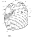
Fig. 1 shows a front perspective view of a first exemplary embodiment of a releasable vest according to this invention; -
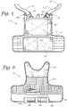
Fig. 2 shows a partially exploded front perspective view of a first exemplary embodiment of a releasable vest according to this invention; -
Fig. 3A shows a partially exploded front view of a first exemplary embodiment of a releasable vest, illustrating a front panel flap in an open position, according to this invention; -
Fig. 3B shows a partial view of the releasable coupling of the waist belt elements and the release lanyard according to this invention; -
Fig. 4 shows a front view of an assembled front panel and waist belt elements of a first exemplary embodiment of a releasable vest, illustrating the front panel flap in a closed but unsecured position, according to this invention; -
Fig. 5 shows a front view of the front panel of the releasable vest, illustrating a front panel flap in an open position; -
Fig. 6 shows a rear view of the front panel of the releasable vest, illustrating the front panel flap in a closed and secured position; -
Fig. 7 shows a rear view of the back panel of the releasable vest, illustrating a back panel flap in a closed but unsecured position; -
Fig. 8 shows a front view of the back panel of the releasable vest, illustrating the back panel flap in a closed but unsecured position; -
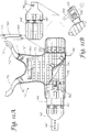
Fig. 9 shows an interior view of the back panel of a first exemplary embodiment of a releasable vest according to this invention, illustrating the back panel flap in an open position and illustrating the releasable coupling of the waist belt elements according to this invention; -
Fig. 10 shows an interior view of the back panel of an additional exemplary embodiment of a releasable vest according to this invention, illustrating the back panel flap in an open position and illustrating the releasable coupling of the shoulder strap elements according to this invention; -
Fig. 11A illustrates a front view of an assembled front panel and waist belt elements of the additional exemplary embodiment of a releasable vest, illustrating the front panel flap in a partially opened position, according to this invention; -
Fig. 11B illustrates a more detailed view of the slidably releasable buckle of the additional exemplary embodiment of a releasable vest according to this invention; -
Fig. 12 illustrates a front view of an assembled front panel and waist belt elements of yet another exemplary embodiment of a releasable vest, illustrating the front panel flap in an opened position, according to this invention; -
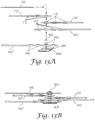
Fig. 13A illustrates a partially exploded view of the slidably releasable coupling of the waist belt elements, shoulder strap elements, and release lanyard according to this invention; -
Fig. 13B illustrates an assembled view of the slidably releasable coupling of the waist belt elements, shoulder strap elements, and release lanyard to the second release loop according to this invention; -
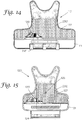
Fig. 14 shows a rear view of the front panel of an exemplary embodiment of the releasable vest, wherein the front panel includes an internal pocket; and -
Fig. 15 shows a rear view of the back panel of an exemplary embodiment of the releasable vest, wherein the back panel includes an internal pocket. - For simplicity and clarification, the design factors and operating principles of the releasable vest of this invention are explained with reference to various exemplary embodiments of a releasable vest. The basic explanation of the design factors and operating principles of the releasable vest is applicable for the understanding, design, and operation of the releasable vest of this invention.
- It should also be appreciated that, for simplicity and clarification, the embodiments of this invention will be described using the terms "front" and "back". However, it should be understood that these terms are merely used to aid in understanding of this invention are not to be construed as limiting the systems, methods, and apparatuses of this invention. Thus, it should be appreciated that the design factors and operating principles of the releasable vest described herein may be used in a "mirror image" releasable vest, where in the elements described as being included in or on the front are included in or on the back. Alternatively certain of the elements that are described as being included in or on the back of the releasable vast may be included in or on the front of the vest, or vice versa.
- Furthermore, it should be appreciated that, for simplicity and clarification, the embodiments of this invention will be shown and/or described with reference to MOLLE and/or S.T.R.I.K.E. compatible webbing being included on various portions of the releasable vest. However, it should be appreciated that the inclusion and/or placement of any MOLLE and/or S.T.R.I.K.E. compatible webbing is not essential to the releasable vest of this invention. In various exemplary, non-limiting embodiments of this invention, the releasable vest may incorporate any type of known or later developed system capable of allowing any number of exterior pouches, pockets, carriers, or the like to be permanently or releasably coupled or attached to the vest. Alternatively, the design factors and principles of this invention may be utilized in a vest that does not include any exterior pouches, pockets, or carriers, but is used as, for example, a ballistic plate carrier or a floatation device.
- It should also be appreciated that the terms "releasable vest", "vest", and "carrier" are used for basic explanation and understanding of the operation of the systems, methods, and apparatuses of this invention. Therefore, the terms "releasable vest", "vest", and "carrier" are not to be construed as limiting the systems, methods, apparatuses, and applications of this invention.
- Turning now to the drawing figures,
Figs. 1 through 9 show various features of a first exemplary embodiment of a releasable vest according to this invention. As shown in the drawing figures, thereleasable vest 100 includes at least some of afront panel 110, frontshoulder strap elements 112, aback panel 120, a firstwaist belt element 140, a second waist belt element 140', arelease loop 160, and arelease lanyard 115. - The
front panel 110 comprises at least afirst layer 111 and asecond layer 114, with a cavity formed between thefirst layer 111 and thesecond layer 114. An upper portion of thesecond layer 114 is attached or coupled to thefirst layer 111 at an upper portion of thefirst layer 111. In various exemplary embodiments, as illustrated herein, a lower portion of thesecond layer 114 extends beyond a point where thesecond layer 114 is attached or coupled to thefirst layer 111 to form a front panel flap portion 114' of thesecond layer 114. - The front panel flap portion 114' is formed so as to be secured or releasably coupled to the
first layer 111 by a releasable coupling means 116. In various exemplary embodiments, the releasable coupling means 116 may comprise a hook and loop fastener, such as Velcro. It should be appreciated that, in various exemplary embodiments the releasable coupling means 116 may comprise other releasable coupling means or releasable fasteners, such as, for example, male/female snap-release buckles, a ziplock fastening device, a zipper, buttons, snaps, or other fastening, closure, or attachment means known by those skilled in the art. - In various exemplary embodiments, as illustrated herein, the front panel flap portion 114' may be formed so as to extend beyond a lower portion of the
first layer 111 and be releasably coupled to a first side of the first layer 111 (a side of thefront panel 110 that faces towards the body of a user wearing the releasable vest 100). Alternatively, the front panel flap portion 114' may be formed so as to be releasably coupled to a second side of the first layer 111 (a side of thefront panel 110 that faces away from the body of a user wearing the releasable vest 100). - In various exemplary embodiments, the
front panel 110 may also comprise an additional layer ofmaterial 122, which provides an additional cushioning or airflow layer to thefront panel 110. Furthermore, thefront panel 110 may comprise a portion ofattachment material 123, such as, for example, a hook and loop fastener, such as Velcro. The inclusion of a portion ofattachment material 123 may allow for the releasable attachment of certain additional components, such as, for example, collars or other protective portions, to thefront panel 110 of thereleasable vest 100. - The
front panel 110 includes two frontshoulder strap elements 112 that extend from an upper portion of thefront panel 110. In various exemplary embodiments, the frontshoulder strap elements 112 are formed as an integral part of thefront panel 100. Alternatively, the frontshoulder strap elements 112 may be coupled or attached to thefront panel 110. - In various exemplary embodiments, each of the front
shoulder strap elements 112 includes a plurality of front shoulderstrap attachment openings 113. In various exemplary, non-limiting embodiments, the front shoulderstrap attachment openings 113 comprise slits or openings formed through the material of the frontshoulder strap elements 112. In certain exemplary embodiments, theattachment openings 113 are reinforced by, for example, stitching, a grommet, or other reinforced eyelet. - The front shoulder
strap attachment openings 113 allow therelease loop 160 to pass through the front shoulder strap elements 112 (as discussed below). In various exemplary embodiments, asingle attachment opening 113 may be included on each frontshoulder strap element 112. However, a plurality ofattachment openings 113 may be included to allow a user to select asingle attachment opening 113 to pass therelease loop 160 through, thereby providing a measure of adjustment to the effective length of the frontshoulder strap elements 112 and the overall fit of thereleasable vest 100. - In various exemplary embodiments, as illustrated in
Figs. 3A ,11A , and12 , a MOLLE and/or S.T.R.I.K.E. compatible accessory mounting portion 170' is included on a portion of the second side of thefirst layer 111. It should be appreciated that the accessory mounting portion 170' may be provided in an area of thefirst layer 111 that is capable of being covered by the front panel flap portion 114' of thesecond layer 114. - Additionally, a MOLLE and/or S.T.R.I.K.E. compatible
accessory mounting portion 170 is included on the second side of thesecond layer 114. - The
back panel 120 comprises at least afirst layer 121 and asecond layer 124, with a cavity formed between thefirst layer 121 and thesecond layer 124. An upper portion of thesecond layer 124 is attached or coupled to thefirst layer 121 at an upper portion of thefirst layer 121. In various exemplary embodiments, as illustrated herein, a lower portion of thesecond layer 124 extends beyond a point where thesecond layer 124 is attached or coupled to thefirst layer 121 to form a back panel flap portion 124' of thesecond layer 124. - In various exemplary embodiments, a
grommet 125 or other panel coupling means is positioned so as to provide additional coupling of thefirst layer 121 to thesecond layer 124. It should be appreciated that, in various exemplary embodiments, thegrommet 125 may be replaced by other permanent or releasable coupling means fasteners, such as, for example, a stitch or stitched portion, one or more male/female snap-release buckles, one or more buttons, snaps, or other fastening, closure, or attachment means known to those skilled in the art. - The back panel flap portion 124' of the
second layer 124 is formed so as to be secured or releasably coupled to thefirst layer 121 by a releasable coupling means 126. In various exemplary embodiments, the releasable coupling means 126 may comprise a hook and loop fastener, such as Velcro. It should be appreciated that, in various exemplary embodiments the releasable coupling means 126 may comprise other releasable coupling means or releasable fasteners, such as, for example, male/female snap-release buckles, a ziplock fastening device, a zipper, buttons, snaps, or other fastening, closure, or attachment means known by those skilled in the art. - In various exemplary embodiments, as illustrated herein, the back panel flap portion 124' may be formed so as to extend beyond a lower portion of the
first layer 121 and be releasably coupled to a first side of the first layer 121 (a side of theback panel 120 that faces towards the body of a user wearing the releasable vest 100). Alternatively, the back panel flap portion 124' may be formed so as to be releasably coupled to a second side of the first layer 121 (a side of theback panel 120 that faces away from the body of a user wearing the releasable vest 100). - In various exemplary embodiments, the
back panel 120 may also comprise an additional layer ofmaterial 122, which provides an additional cushioning or airflow layer to theback panel 120. Furthermore, theback panel 120 may comprise a portion ofattachment material 123, such as, for example, a hook and loop fastener, such as Velcro. The inclusion of a portion ofattachment material 123 may allow for the releasable attachment of certain additional components, such as, for example, collars or other protective portions, to theback panel 120 of thereleasable vest 100. - The
back panel 120 comprises a cavity or tunnel formed between at least a portion of thefirst layer 121 and thesecond layer 124. In this manner, at least a portion of the frontshoulder strap elements 112 can be introduced into an interior of theback panel 120 formed between at least a portion of thefirst layer 121 and thesecond layer 124. - The
waist belt elements 140 and 140' serve to attach or couple thefront panel 110 to theback panel 120. As illustrated in the drawing figures, the firstwaist belt element 140 is releasably attached or coupled to thefirst layer 111 of thefront panel 110, via the interaction of a releasable fastening means 143 on waist belt attachment /adjustment portions 145 of the firstwaist belt element 140 and corresponding releasable fastening means 119 on thefirst layer 111 of thefront panel 110. In various exemplary embodiments, the releasable fastening means 143 is positioned on a first side of the firstwaist belt element 140 proximate a first end of the firstwaist belt element 140. - In various exemplary embodiments, the releasable fastening means 143 and the corresponding releasable fastening means 119 comprise mating portions of a hook and loop fastener, such as Velcro®. It should be appreciated that, in various exemplary embodiments, the releasable fastening means 143 and the corresponding releasable fastening means 119 comprise other attachment means or releasable fasteners, such as, for example, other hook-and-loop fasteners, male/female snap-release buckles, buttons, snaps, or other fastening, closure, or other known or later developed fastening or attachment means.
- In various exemplary embodiments, a second portion of a releasable fastening means 143' is included on a second side of the first
waist belt element 140 proximate the first end of the firstwaist belt element 140. Additionally, a second portion of corresponding releasable fastening means 119' is included on an inner layer of the front panel flap portion 114' of thesecond layer 114. - In this manner, each of the
waist belt elements 140 and 140' can be releasably secured, on a first side, to the releasable fastening means 119 on thefirst layer 111 of thefront panel 110. Optionally, each of thewaist belt elements 140 and 140' may be further releasably secured, on a second side, to the releasable fastening means 119' on an inner layer of the front panel flap portion 114' of thesecond layer 114. - In various exemplary embodiments, the
waist belt elements 140 and/or 140' optionally include one or moreelastic portions 147. If included, the elastic portion(s) 147 provide a measure of stretch or flex to thewaist belt elements 140 and 140'. While the elastic portion(s) 147 are illustrated as comprising three separate elastic portions attached or coupled between sections of thewaist belt elements 140 and/or 140', it should be appreciated that the elastic portion(s) 147 may comprise a single elastic portion attached a couple between sections of thewaist belt elements 140 and/or 140'. - As Illustrated in
Figs. 3A, 3B ,13A, and 13B , therelease loop 160 is attached or coupled to a portion of fabric orother material 165. In various exemplary embodiments, therelease loop 160 comprises a loop made of a fabric, metallic, plastic, or composite material. Optionally, a portion of releasable fastening means 166, such as, for example, Velcro®, is included on the top side of thematerial 165. In this manner, the portion ofmaterial 165 may be attached or coupled to a first side of the firstwaist belt element 140 or the second waist belt element 140', particularly after a portion of therelease loop 160 is passed through an appropriate waistbelt attachment opening 142. - As further illustrated herein, each of the first
waist belt element 140 and the second waist belt element 140' includes one or more waist belt attachment opening(s) 142, which are capable of including or accommodating therelease loop 160. - In certain exemplary, non-limiting embodiments, the waist belt attachment opening(s) 142 comprise slits or openings formed through the material of the first
waist belt element 140 and the second waist belt element 140'. In certain exemplary embodiments, the waist belt attachment opening(s) 142 are reinforced by, for example, stitching, a grommet, or other reinforced eyelet. - The waist belt attachment opening(s) 142 allow the
release loop 160 to pass through thewaist belt elements 140 and 140' (as discussed below). In various exemplary embodiments, asingle attachment opening 142 may be included on eachwaist belt elements 140 and 140'. However, a plurality of waist belt attachment opening(s) 142 may be included to allow a user to select a single waist belt attachment opening 142 to pass therelease loop 160 through, thereby providing a measure of adjustment to the effective length of thewaist belt element 140 or 140'and the overall fit of thereleasable vest 100. - The
release lanyard 115 comprises an elongate piece of material having a relatively thin profile. By utilizing arelease lanyard 115 having a relatively thin profile, the possibility of therelease lanyard 115 producing a pressure point on the user is greatly reduced. However, it should be appreciated that therelease lanyard 115 may have a round or oval shaped profile. In various exemplary embodiments, therelease lanyard 115 comprises a material having a relatively low coefficient of drag. - In various exemplary embodiments, the
release lanyard 115 may comprise a single piece of material that extends from a pull handle 115' to a terminal end. Alternatively, therelease lanyard 115 may comprise a variety of materials that are attached or coupled together to form therelease lanyard 115. For example, the elongate body portion of therelease lanyard 115 may be comprised of a different material from a pull handle 115'. - In various exemplary embodiments, a portion of the exterior of the
front panel 110, theback panel 120, and/or thewaist belt elements 140 and 140' includes MOLLE and/or S.T.R.I.K.E. compatible webbing. However, it should be appreciated that the inclusion of any such MOLLE and/or S.T.R.I.K.E. compatible webbing is a design choice based on the desired appearance and functionality of thereleasable vest 100. - If, as illustrated herein, the
waist belt elements 140 and 140' include MOLLE and/or S.T.R.I.K.E.compatible webbing 144 and 144', respectively, an accessory pouch or carrier, such as, for example, anarmor plate carrier 190 for holding an armor plate 198 may be coupled to one or both of thewaist belt elements 140 and 140'. As illustrated inFig. 4 , anarmor plate carrier 190 may be coupled, viacoupling members 150, to the second waist belt element 140'. As illustrated, thearmor plate carrier 190 is placed adjacent the second waist belt element 140', such that waist belt webbings 144' are within the spaces between spaced apart armor plate carrier webbings 194 (and the armor plate carrier webbings 194 are within spaces between the spaced apart waist belt webbings 144') and corresponding plate carrier tunnel segments and waist belt tunnel segments are aligned, thecoupling member 150 may be interwoven between the aligned plate carrier tunnel segments and waist belt tunnel segments to removably couple the second waist belt element 140' to the armorplate carrier webbing 194, similarly to the method described above with reference toFig. 11A . - It should be appreciated that while the
armor plate carrier 190 is illustrated as being coupled to a second side of the second waist belt element 140', thearmor plate carrier 190, or any other accessory or accessory carrier, may be coupled to any portion of MOLLE and/or S.T.R.I.K.E. compatible webbing on thereleasable vest 100. For example, thearmor plate carrier 190 may be coupled to the MOLLE and/or S.T.R.I.K.E. compatible accessory mounting portion 170' included on the second side of thefirst layer 111, such that thearmor plate carrier 190 is coupled between thefront panel 110 and the firstwaist belt element 140 or the second waist belt element 140'. - In various exemplary embodiments, the
front panel 110, theback panel 120, and/or thewaist belt elements 140 and 140' may include a pocket or plate carrier, such as, for example, afront pocket 180 and/or aback pocket 182. However, it should be appreciated that the inclusion of any such pocket or plate carrier is a design choice based on the desired appearance and functionality of thereleasable vest 100. - If the
back pocket 182 is included, thegrommet 125 may serve as a drain hole for theback pocket 182. Additionally, if thefront pocket 180 and/or additionalwaist belt elements 140 and 140' include one or more pockets, additional grommets, not show may be included to provide drainage for each of the pockets. - One optional method for assembling the elements of the
releasable vest 100 includes first securing thewaist belt elements 140 and 140' to thefront panel 110, as discussed above. - Then, the back panel flap portion 124' is lifted and the
waist belt elements 140 and 140' are positioned atop the lower portion of thefirst layer 121, such that therelease loop 160 can be aligned with and passed through the appropriate waistbelt attachment openings 142 of thewaist belt elements 140 and 140'. - When the
release loop 160 has been passed through the aligned waistbelt attachment openings 142, an end of a first frontshoulder strap element 112 is introduced into an interior tunnel or cavity of theback panel 120 and passed through the tunnel or cavity of theback panel 120 such that therelease loop 160 can be aligned with and passed through an appropriate front shoulderstrap attachment opening 113. - When an appropriate front shoulder strap attachment opening 113 has been aligned with the
release loop 160, therelease loop 160 is passed through the aligned front shoulderstrap attachment opening 113. - Once the
release loop 160 has been passed through a front shoulder strap attachment opening 113 of a first front shoulder strap element 112 (identified inFig. 13B as first shoulder strap element 112), an end of a second frontshoulder strap element 112 is passed through an interior tunnel or cavity of theback panel 120 and therelease loop 160 is passed through an appropriately aligned front shoulder strap attachment opening 113 of the second front shoulder strap element 112 (identified inFig. 13B as second shoulder strap element 112'). - When the
release loop 160 has been passed through the desired waist belt attachment opening 142 of thewaist belt elements 140 and 140' and the desired front shoulderstrap attachment openings 113 of the frontshoulder strap elements 112 and 112', a portion of therelease lanyard 115 is passed through therelease loop 160 to secure thewaist belt elements 140 and 140' and the frontshoulder strap elements 112 and 112' together, as illustrated inFigs. 13A and 13B . - In various exemplary embodiments, the
release lanyard 115 follows a path that parallels the path taken by one of the frontshoulder strap elements 112. To maintain an appropriate position of therelease lanyard 115, release lanyard guides, such as, for example, release lanyard guides 118, may be included on various portions of the frontshoulder strap elements 112. Alternatively, similar release lanyard guides may be included in the interior of theback panel 120, attached or couple to either thefirst layer 121 or thesecond layer 124. - In various exemplary embodiments, the
release lanyard 115 is of a sufficient length such that when thereleasable lanyard 115 is passed through therelease loop 160, the pull handle 115' is at least partially covered by arelease lanyard cover 117. Therelease lanyard cover 117 provides at least some measure of security that therelease lanyard 115 is not accidentally pulled. - In various exemplary embodiments, at least a portion of the
release lanyard 115 includes a frictional surface (not shown). The frictional surface, if included, can provide a certain amount of resistance to therelease lanyard 115 being pulled from thereleasable vest 100 and/or therelease lanyard cover 117, when thereleasable vest 100 is fully assembled. - It should be appreciated that the order in which the components of the
releasable vest 100 are described as being assembled may be altered so that a user is able to achieve the best fit of thereleasable vest 100. For example, as described in shown herein, therelease loop 160 may be releasably coupled to the remaining firstwaist belt element 140 before therelease loop 160 is releasably coupled to theshoulder strap elements 112. Alternatively, therelease loop 160 may first be releasably coupled to theshoulder strap elements 112 before therelease loop 160 is releasably coupled to the remaining firstwaist belt element 140. - When the
waist belt elements 140 and 140' and theshoulder strap elements 112 and 112' have been releasably coupled, via thereleasable lanyard 115, to thereleasable loop 160, the back panel flap portion 124' is closed and secured, via releasable coupling means 126, to thefirst layer 121. - Because the assembled combination of the
waist belt elements 140 and 140' and theshoulder strap elements 112 is relatively free-floating with respect to theback panel 120, thegrommet 125, if included, may provide an upper limit for the assembled combination of thewaist belt elements 140 and 140' and theshoulder strap elements 112, such that these elements may be held in a desired position relative to theback panel 120. - When the elements of the
releasable vest 100 have been assembled, the assembledreleasable vest 100 may be donned or removed by a user utilizing the waist belt attachment /adjustment portions 145. Alternatively, if thewaist belt elements 140 and/or 140' are formed integral to thefront panel 110, an elastic portion of thewaist belt elements 140 and/or 140' may provide sufficient flex to allow thereleasable vest 100 to be donned or removed by the user. - If a wearer wishes to quickly remove the
releasable vest 100, thereleasable lanyard 115 need only be pulled a relatively short distance. When the pull handle 115' of thereleasable lanyard 115 is pulled, therelease lanyard 115 is slidably pulled from therelease loop 160, and thewaist belt elements 140 and 140' and frontshoulder strap elements 112 are able to separate from therelease loop 160, and theback panel 120. Thus, when the pull handle 115' is pulled, the elements of thereleasable vest 100 are released and the vest can "fall away" from the body of the user. - In various exemplary embodiments, the
releasable vest 100 may further comprise a second, safety lanyard (not shown), which may also be slidably passed through therelease loop 160. The safety lanyard operates similarly to therelease lanyard 115. However, the safety lanyard, if utilized, requires that a second obstruction be removed from therelease loop 160 before the elements of thereleasable vest 100 are able to separate from therelease loop 160. - In certain exemplary embodiments, the safety lanyard may comprise a loop of material or a ring, such as, for example, a locking or snap carabiner, that is slidably passed through the
release loop 160 after the elements of thereleasable vest 100 have been slidably releasably coupled to therelease loop 160. In various exemplary embodiments, release of the safety lanyard may require access through the back panel flap portion 124'. - It is possible that a safety lanyard be used in place of the
release lanyard 115. In this manner, the releasable features and capabilities of the vest are overcome and the elements remain coupled until the safety lanyard is removed. - In various exemplary embodiments, instructions for assembling and/or operating the
releasable vest 100 may be included on thefirst layer 121 or on an inside layer or surface of the back panel flap portion 124'. In this manner, when the back panel flap portion 124' is lifted so that a user is able to assemble the components of thereleasable vest 100, instructions for the assembly and/or operation of thereleasable vest 100 are provided. The instructions may be provided in written, pictorial, diagram, or a combination of forms. - Alternatively, instructions for assembling and/or operating the
releasable vest 100 may be included on thesecond layer 124 of theback panel 120. The instructions may be provided in written, pictographic, diagram, symbolic, or a combination of forms and may, for example, include a pictorial outline of certain of the components illustrating the relationship of each of the components when assembled or illustrating how the components are to be assembled. - While optional instructions have been described as being included on the inside layer or surface of the back panel flap portion 124' or the
first layer 121 of theback panel 120, the optional instructions may be included on any covered or exposed surface of any component of thereleasable vest 100. - While not illustrated herein, in various exemplary embodiments, the
releasable vest 100 may comprises afirst release loop 160 and a second release loop 162 (not shown), both of which are attached or coupled to one of thewaist belt elements 140 and 140'. It should be appreciated that thefirst release lanyard 160 and the second release loop 162 (not shown) operate similarly to therelease loop 160, as described above. - However, with the inclusion of the second release loop 162 (not shown), certain components may be releasably coupled to the
first release loop 160 while certain other components are releasably coupled to the second release loop 162 (not shown). For example, the remaining firstwaist belt element 140 may be releasably slidably coupled to thefirst release loop 160, while the frontshoulder strap elements 112 may be releasably slidably coupled to the second release loop 162 (not shown). - In this manner, the
releasable lanyard 115 may be passed through thefirst release loop 160 and a second release loop 162 (not shown) to secure the frontshoulder strap elements 112 and thewaist belt elements 140 and 140', respectively. - Utilizing a
first release loop 160 and a second release loop 162 (not shown), when therelease lanyard 115 is pulled a first distance, the elements of thereleasable vest 100 that are coupled to thefirst release loop 160 are able to separate from thefirst release loop 160. Then, when therelease lanyard 115 is pulled a second distance, the elements of thereleasable vest 100 that are coupled to the second release loop 162 (not shown) are able to separate from the second release loop 162 (not shown). - In this manner, certain of the components of the
releasable vest 100 are released from the assembled relationship when therelease lanyard 115 is pulled a first predetermined distance. When therelease lanyard 115 is pulled a second predetermined distance, certain remaining components of thereleasable vest 100 are released from the assembled relationship. - If, for example, the
release lanyard 115 is accidentally pulled, it is possible that only one of thewaist belt elements 140 will be released from the second release loop 162 (not shown), alerting the user to the fact that therelease lanyard 115 has been accidentally pulled, before all of the elements of thereleasable vest 100 are released from their assembled relationship. -
Figs. 10 through 12 show an additional exemplary embodiment of a releasable vest according to this invention. As illustrated inFigs. 10 through 12 , the releasable fastening means 143 and 143' on waist belt attachment /adjustment portions 145 and 145' of thewaist belt elements 140 and 140', as well as the corresponding releasable fastening means 119 on thefirst layer 111 of thefront panel 110 are removed. As illustrated inFigs. 10 through 12 , the releasable fastening means 143 and 143' is replaced by abuckle 175 having a bucklingelement 177. Furthermore, the releasable fastening means 119 is replaced by a MOLLE and/or S.T.R.I.K.E. compatible accessory mounting portion 170' that extends through in an area of thefirst layer 111 that is capable of being covered by the front panel flap portion 114' of thesecond layer 114. - Thus, the first
waist belt element 140 is releasably coupled or attached to thefirst layer 111 of thefront panel 110, via acoupling member 150. - Each
coupling member 150 comprises an elongate portion of material having afirst end portion 152, anintermediate portion 155, and asecond end portion 156. As illustrated inFig. 11A , ahook 153 is formed integral to a portion of thefirst end portion 152 and ahook 157 is formed integral to a portion of thesecond end portion 156. - In various exemplary, non-limiting embodiments, the
coupling member 150 comprises a coupling member as described inUS 8,079,503 . - As illustrated in
Figs. 10 through 12 , the firstwaist belt element 140, and possibly the second waist belt element 140' is coupled to thefirst layer 111 of thefront panel 110, via the accessory mounting portion 170'. - In order to couple the
waist belt element 140 and/or 140' to thefront panel 110, thewaist belt element 140 or 140', thecoupling member 150 is first interwoven between panel tunnel segments (or merely inserted between the MOLLE and/or S.T.R.I.K.E. compatible webbing segments and the surface of the front panel 110) to removably couple thecoupling member 150 to the accessory mounting portion 170'. - Once the
coupling member 150 has been removably coupled to the accessory mounting portion 170', thehooks coupling member 150 within the panel tunnel segments. - It should be understood that since the total number of spaced apart accessory mounting portions 170' may vary, the total length of the
coupling member 150 may vary. - Once the
coupling member 150 has been removably coupled to the accessory mounting portion 170', thebuckle 175 can be attached to thecoupling member 150, as illustrated inFigs. 11A through 12 . - It should be appreciated that, as illustrated in
Figs. 10 through 11B , thebuckle 175 may be used to attach or couple only onewaist belt element 140 or 140' to the accessory mounting portion 170'. Alternatively, as illustrated inFig. 12 , thebuckle 175 may be utilized in connection with the firstwaist belt element 140 and the second waist belt element 140' and used to separately attach or couple bothwaist belt elements 140 and 140' to the accessory mounting portion 170'. -
Figs. 13A and 13B show a more detailed view of arelease loop 160 being utilized in conjunction with thewaist belt elements 140 and 140', the frontshoulder strap elements 112 and 112', and therelease lanyard 115 according to this invention. - As illustrated in
Figs. 13A and 13B , therelease loop 160 is attached or coupled to a portion ofmaterial 165. The overall size and shape of the portion of thematerial 165 is such that the attachedrelease loop 160 will not be pulled through any of the waistbelt attachment openings 142 or the shoulderstrap attachment openings 113. - The optional portion of releasable fastening means 166, included on the top side of the
material 165, allows the portion ofmaterial 165 to be attached or coupled to a first side of the firstwaist belt element 140 or the second waist belt element 140', particularly after a portion of therelease loop 160 is passed through an appropriate waistbelt attachment openings 142. - Alternatively, the
material 165 may include an aperture or other means formed in or on thematerial 165 that allows thematerial 165 to be attached or coupled to a portion of a waist belt element or other element of thevest 100. In this manner, thematerial 165 andrelease loop 160 may be kept with an element of thevest 100 so as not to be inadvertently lost. For example, a piece of 550 cord may be used to couple the material 165 to the second waist belt element 140'. - In certain exemplary embodiments, the
material 165 may comprise a loop or ring of material, such as metal or plastic loop or ring, that is attached or coupled to therelease loop 160 such that the overall size and shape of the loop or ring is such that the attachedrelease loop 160 will not be pulled through any of the waistbelt attachment openings 142 or the shoulderstrap attachment openings 113. Alternatively, the release loop may be knotted at one end, stitched over upon itself, or stitched to another material so as to provide sufficient size to a portion of therelease loop 160 such that he releaseloop 160 will not be pulled completely through any of the waistbelt attachment openings 142 or the shoulderstrap attachment openings 113. - As illustrated, the
release loop 160 may comprise a loop of material, such as, for example, 550 cord or webbing material, that is sewn or otherwise attached to the portion ofmaterial 165 such that therelease loop 160 is kept from passing through the waistbelt attachment openings 142. - In these exemplary embodiments, both the first
waist belt element 140 and the second waist belt element 140' include one or more waist belt attachment opening(s) 142. During assembly, the appropriate waistbelt attachment openings 142 and the appropriate front shoulderstrap attachment openings 113 are aligned and therelease loop 160 is passed through the aligned waistbelt attachment openings 142 and front shoulderstrap attachment opening 113. Once a portion of therelease loop 160 has passed through the openings, sufficient that a portion of therelease lanyard 115 may be passed through therelease loop 160 to secure thewaist belt elements 140 and 140' and the frontshoulder strap elements 112 and 112' together, therelease loop 160 is maintained in position via therelease lanyard 115 and the knot or other obstruction formed in therelease loop 160. -
Figs. 14 and 15 show exemplary embodiments of a releasable vest wherein the exemplaryfront pocket 180 and backpocket 182 are replaced or supplemented by a frontinternal pocket 280 and a backinternal pocket 282, respectively. In these exemplary embodiments, thefirst layer 111 of thefront panel 110 comprises a frontinternal pocket 280, which is accessible when the front panel flap portion 114' of thesecond layer 114 is opened. Likewise, thefirst layer 121 of theback panel 120 comprises a backinternal pocket 282, which is accessible when the back panel flap portion 124' of thesecond layer 124 is opened. - Items, such as, for example,
body armor plates 199 may be inserted in the frontinternal pocket 280 and/or the backinternal pocket 282. Once the items are inserted, the front panel flap portion 114' and/or the back panel flap portion 124' can be closed to secure the items within the frontinternal pocket 280 and/or the backinternal pocket 282. - It should be appreciated that the inclusion of any external and/or internal pocket or plate carrier is a design choice based on the desired appearance and functionality of the
releasable vest 100. - While this invention has been described in conjunction with the exemplary embodiments outlined above, it is evident that many alternatives, modifications, and variations will be apparent to those skilled in the art. Such adaptations and modifications should and are intended to be comprehended within the meaning and range of equivalents of the disclosed exemplary embodiments. It is to be understood that the phraseology of terminology employed herein is for the purpose of description and not of limitation. Accordingly, the foregoing description of the exemplary embodiments of the invention, as set forth above, is intended to be illustrative, not limiting. Various changes, modifications, and/or adaptations may be made without departing from the scope of this invention, which is defined in the claims.
Claims (14)
- A releasable vest (100), comprising:a front panel (110) comprising at least a first layer (111) and a second layer (114), wherein the first layer (111) of the front panel (110) includes at least a portion of a releasable fastening means (119), wherein an upper portion of the second layer (114) is attached to the first layer (111) and wherein a lower portion of the second layer (114) extends beyond an area where the second layer (114) is attached or coupled to the first layer (111) to form a front access panel portion (114') of the second layer (114), and wherein a releasable coupling means (116) releasably couples the front access panel portion (114') of the second layer (114) to the first layer (111) so as to cover at least a portion of a first waist belt element (140);front shoulder strap elements (112) that extend from an upper portion of the front panel (110), wherein each of the front shoulder strap elements (112) includes at least one front shoulder strap attachment opening (113) formed through a material of the front shoulder strap element (112);a back panel (120) comprising at least a first layer (121) and a second layer (124), wherein an upper portion of the second layer (124) is attached to the first layer (121) such that a cavity is formed between at least a portion of the first layer (121) and the second layer (124) such that at least a portion of the front shoulder strap elements (112) can be introduced into the cavity formed between at least a portion of the first layer (121) and the second layer (124), and wherein a lower portion of the second layer (124) extends beyond an area where the second layer (124) is attached or coupled to the first layer (121) to form a back access panel portion (124') of the second layer (124), wherein a releasable coupling means releasably couples the back access panel portion (124') of the second layer (124) to the first layer (121);the first waist belt element (140) being releasably attached or coupled, via interaction between the releasable fastening means (119) of the first layer (111) of the front panel (110) and corresponding releasable fastening means (143) of the first waist belt element (140), to a lower portion of the front panel (110) such that the first waist belt element (140) extends from a lower portion of the front panel (110), wherein the first waist belt element (140) comprises at least one waist belt element attachment opening (142) formed through the material of the waist belt element;a second waist belt element (140') releasably attached or coupled, via interaction between the releasable fastening means (119) of the first layer (111) of the front panel (110) and corresponding releasable fastening means (143) of the second waist belt element (140'), to a lower portion of the front panel (110) such that the second waist belt element (140') extends from a lower portion of the front panel (110);at least one release loop (160) capable of being aligned with and passed through the waist belt attachment opening (142) of the first waist belt element (140) and the at least one front shoulder strap attachment opening (113) of each of the front shoulder strap elements (112); anda release lanyard (115), wherein the release lanyard (115) extends from a pull handle (115') to a terminal end, and wherein the release lanyard (115) is capable of being aligned with and passed through the release loop (160) so as to releasably secure the first waist belt element (140) and the at least one shoulder strap element (112) to the release loop (160),characterized by:a panel coupling means (125) that further couples the first layer (121) of the back panel (120) to the second layer (124) of the back panel (124);wherein the second waist belt element (140') comprises the at least one release loop (160) attached directly to the second waist belt element (140'); andwherein the panel coupling means (125) provides an upper limit for an assembled combination of the waist belt elements (140, 140') and the front shoulder strap elements (112), such that the waist belt elements (140, 140') and the front shoulder strap elements (112) are held in a desired position relative to the back panel (120).
- The releasable vest (100) of claim 1, wherein the front shoulder strap elements (112) are formed as an integral part of the front panel (110).
- The releasable vest (100) of claim 1, wherein the front shoulder strap elements (112) are releasably attached to the front panel (110).
- The releasable vest (100) of claim 1, wherein each of the front shoulder strap elements (112) includes a plurality of front shoulder strap attachment openings (113).
- The releasable vest (100) of claim 1, wherein the front shoulder strap attachment openings (113) are reinforced by stitching, a grommet, or a reinforced eyelet.
- The releasable vest (100) of claim 1, wherein the panel coupling means (125) comprises a grommet, a stitch, a stitched portion, one or more male/female snap-release buckles, one or more buttons, or one or more snaps.
- The releasable vest (100) of claim 1, wherein the front access panel portion (114') of the second layer (114) extends beyond a lower portion of the first layer (111) and is releasably coupled to a second side of the first layer (111).
- The releasable vest (100) of claim 1, wherein the back access panel portion (124') of the second layer (124) extends beyond a lower portion of the first layer (121) and is releasably coupled to a second side of the first layer (121).
- The releasable vest (100) of claim 1, wherein the second waist belt element (140') is removably coupled, via one or more coupling members (150), to MOLLE or S.T.R.I.K.E. compatible accessory mounting portions (170') formed on the front panel (110).
- The releasable vest (100) of claim 1, wherein the waist belt elements (140, 140') include an elastic portion (147) to allow for a measure of expansion of the waist belt elements (140, 140').
- The releasable vest (100) of claim 1, wherein each of the waist belt elements (140, 140') includes a plurality of waist belt attachment openings (142).
- The releasable vest (100) of claim 1, wherein the release loop (160) comprises a fabric, metallic, plastic, or composite material.
- The releasable vest (100) of claim 1, wherein the releasable fastening means (119) and the corresponding releasable fastening means (143) comprise mating portions of a hook and loop fastener, male/female snap-release buckles, buttons, or snaps.
- The releasable vest (100) of claim 1, wherein at least one waist belt element (140, 140') includes a buckle (175) that is capable of being releasably attached, via a coupling member (150), to the front panel (110).
Applications Claiming Priority (2)
| Application Number | Priority Date | Filing Date | Title |
|---|---|---|---|
| US1180008P | 2008-01-22 | 2008-01-22 | |
| PCT/US2009/000243 WO2009126190A2 (en) | 2008-01-22 | 2009-01-15 | Releasable vest |
Publications (3)
| Publication Number | Publication Date |
|---|---|
| EP2240043A2 EP2240043A2 (en) | 2010-10-20 |
| EP2240043A4 EP2240043A4 (en) | 2016-03-09 |
| EP2240043B1 true EP2240043B1 (en) | 2017-05-31 |
Family
ID=41162426
Family Applications (1)
| Application Number | Title | Priority Date | Filing Date |
|---|---|---|---|
| EP09729489.6A Not-in-force EP2240043B1 (en) | 2008-01-22 | 2009-01-15 | Releasable vest |
Country Status (4)
| Country | Link |
|---|---|
| US (3) | US8898814B2 (en) |
| EP (1) | EP2240043B1 (en) |
| AU (1) | AU2009234446B2 (en) |
| WO (1) | WO2009126190A2 (en) |
Families Citing this family (35)
| Publication number | Priority date | Publication date | Assignee | Title |
|---|---|---|---|---|
| US8826462B2 (en) * | 2007-11-01 | 2014-09-09 | Alliant Techsystems Inc. | Releasable vest |
| EP2405777B1 (en) | 2009-03-13 | 2017-10-04 | Thf Innovation Pty Ltd | Quick release garment |
| WO2012058199A1 (en) * | 2010-10-26 | 2012-05-03 | Illinois Tool Works Inc. | Quick release vest system |
| US9055773B2 (en) * | 2011-01-13 | 2015-06-16 | Lineweight Llc | Lightweight equipment carrying garment |
| US9993039B2 (en) * | 2012-11-30 | 2018-06-12 | 5.11, Inc. | Garment with plate carrying system |
| US10281240B2 (en) * | 2013-01-14 | 2019-05-07 | FirstSpear, LLC | Modular armor supplement apparatus and system with silent fasteners and adjustability |
| US20210060365A1 (en) * | 2013-05-16 | 2021-03-04 | Norman E. Wood | FireCoat FEDS (Fullbody Emergency Descent System) |
| US9250041B2 (en) * | 2013-09-26 | 2016-02-02 | Warwick Mills Inc. | Shapable armor for users |
| US9943125B2 (en) * | 2013-10-04 | 2018-04-17 | Point Blank Enterprises, Inc. | Quick release tuck strap |
| WO2015164382A1 (en) * | 2014-04-21 | 2015-10-29 | Maybank Joseph | Impact sensing ballistic vest and method for communicating data thereof |
| GB2530064B (en) * | 2014-09-11 | 2016-08-24 | Thales Holdings Uk Plc | A harness |
| USD767824S1 (en) * | 2015-01-17 | 2016-09-27 | Blue Force Gear, Inc. | Utility garment |
| US10495418B2 (en) * | 2016-01-14 | 2019-12-03 | Angel Armor, Llc | Releasably engagable system of ballistic resistant panels |
| USD792027S1 (en) * | 2016-06-07 | 2017-07-11 | Kwikspace Guam | Safety vest |
| USD813651S1 (en) | 2016-06-29 | 2018-03-27 | Tenacious Holdings, Inc. | Lanyard with carabiner |
| USD802845S1 (en) * | 2016-10-28 | 2017-11-14 | Errol Blackwell | Lighted vest |
| USD844251S1 (en) * | 2017-01-13 | 2019-03-26 | Safariland, Llc | Wearable item |
| US10010160B1 (en) * | 2017-07-21 | 2018-07-03 | Mollotek Llc | Load-supporting garment |
| CN111051807A (en) * | 2017-08-01 | 2020-04-21 | S&S精密有限公司 | Bearing harness |
| US20190200572A1 (en) * | 2017-12-29 | 2019-07-04 | Central Lake Armor Express, Inc. | Canine ballistic carrier vest |
| US11243050B2 (en) | 2018-11-28 | 2022-02-08 | 5.11, Inc. | Plate carrier absorption of shock from movement of wearer |
| US11079203B2 (en) * | 2019-03-22 | 2021-08-03 | Aardvark | Three-piece tactical cummerbund |
| US11779064B2 (en) * | 2019-08-16 | 2023-10-10 | Safariland, Llc | Adapter system for vest closure mechanisms |
| USD938656S1 (en) * | 2019-11-26 | 2021-12-14 | Safe Life Defense, Llc | Protective vest |
| USD939148S1 (en) * | 2019-11-26 | 2021-12-21 | Safe Life Defense, Llc | Protective vest |
| USD940798S1 (en) * | 2020-04-08 | 2022-01-11 | Coulter Ventures, Llc. | Weight carrier vest |
| US12064025B2 (en) * | 2020-08-06 | 2024-08-20 | Javlin Concepts, LLC | Chest-worn tactical gear support assembly |
| CN214317295U (en) * | 2021-01-22 | 2021-10-01 | 游慧云 | Burden-reducing vest bag |
| US20220325984A1 (en) * | 2021-02-02 | 2022-10-13 | Amir Tayyebi Moghaddam | Tension Memory System for Wearable Equipment |
| US11564459B2 (en) | 2021-03-30 | 2023-01-31 | Central Lake Armor Express, Inc. | Buckle assembly |
| USD979849S1 (en) * | 2021-03-30 | 2023-02-28 | Central Lake Armor Express, Inc. | Ballistic carrier garment |
| USD979848S1 (en) * | 2021-03-30 | 2023-02-28 | Central Lake Armor Express, Inc. | Ballistic carrier garment |
| US11385028B1 (en) * | 2021-05-05 | 2022-07-12 | Point Blank Enterprises, Inc. | Removable and stowable throat guard |
| US12527365B2 (en) * | 2023-08-28 | 2026-01-20 | Agilite Ergonomics (E.B.) Ltd. | Adjustable fit tactical vest |
| US20250288029A1 (en) * | 2024-03-15 | 2025-09-18 | Donald Paul Meeker | Modular utility latching system |
Family Cites Families (30)
| Publication number | Priority date | Publication date | Assignee | Title |
|---|---|---|---|---|
| US3095587A (en) * | 1961-02-10 | 1963-07-02 | Milton W Whalen | Life jacket |
| US3452362A (en) * | 1967-04-12 | 1969-07-01 | Us Army | Torso armor carrier |
| US5148582A (en) * | 1991-08-08 | 1992-09-22 | Dennis Jr David B | Quick release cord strap system |
| US5617582A (en) * | 1996-06-25 | 1997-04-08 | Burwell; Daniel G. | Load bearing vest |
| US6185738B1 (en) * | 1999-03-16 | 2001-02-13 | Site Enterprises Of Colorado, Inc. | Tactical load-bearing protective vest |
| US6769137B2 (en) * | 2001-10-24 | 2004-08-03 | D'annunzio Timothy B. | Cutaway vests |
| US6446273B1 (en) * | 2001-10-29 | 2002-09-10 | Sherry S. Gillen | Protective body vest |
| US7987523B2 (en) * | 2003-07-08 | 2011-08-02 | Eagle Industries Unlimited, Inc. | Quick release garment |
| US7047570B2 (en) * | 2003-07-08 | 2006-05-23 | Eagle Industries Unlimited, Inc. | Cut away vest |
| US7020897B2 (en) * | 2003-07-08 | 2006-04-04 | Eagle Industries Unlimited, Inc. | Cut away vest |
| US8002159B2 (en) * | 2004-11-29 | 2011-08-23 | S.O. Tech Special Operations Technologies, Inc. | Interlock attaching strap |
| US7536728B1 (en) * | 2005-06-09 | 2009-05-26 | Mine Safety Appliances Company | Body armor and closure mechanism for use in body armor |
| US7200871B1 (en) * | 2005-10-07 | 2007-04-10 | Safari Land Ltd., Inc. | Fabric for load bearing vests having a pocket fastening system |
| US20070289045A1 (en) * | 2006-02-08 | 2007-12-20 | Eagle Industries Unlimited, Inc. | Garment and load attachment system |
| US20090282595A1 (en) * | 2006-05-30 | 2009-11-19 | The Board Of Regents For Oklahoma State University | Antiballistic Garment |
| US7424748B1 (en) * | 2006-06-06 | 2008-09-16 | Eagle Industries Unlimited, Inc. | Quick release system for armor plates in a ballistic resistant vest and method |
| US7814567B2 (en) * | 2006-06-09 | 2010-10-19 | First Choice Armor & Equipment, Inc. | Protective garment having a quick release system |
| US20110179539A1 (en) * | 2006-06-09 | 2011-07-28 | Dovner Edward R | Protective garment system with weight transfer elements |
| US8418265B1 (en) * | 2006-08-25 | 2013-04-16 | Alliant Techsystems Inc. | Releasable vest |
| US8490212B1 (en) * | 2007-02-05 | 2013-07-23 | Eagle Industries Unlimited, Inc. | Quick release garment |
| MX2009009010A (en) * | 2007-02-22 | 2010-03-10 | Edward Dovner | Protective garments having quick release systems and associated methods. |
| US7917967B2 (en) * | 2007-05-08 | 2011-04-05 | Survival Armor, Inc. | Front break away ballistics vest |
| US7979917B2 (en) * | 2007-05-08 | 2011-07-19 | Survival Armor, Inc. | Rear break away ballistics vest |
| US8595862B2 (en) * | 2007-08-02 | 2013-12-03 | Alliant Techsystems Inc. | Releasable vest |
| EP2198236B1 (en) * | 2007-10-08 | 2014-01-08 | MKU PVT Ltd. | Quickly releasable vest |
| US8826462B2 (en) * | 2007-11-01 | 2014-09-09 | Alliant Techsystems Inc. | Releasable vest |
| US8353065B1 (en) * | 2008-01-10 | 2013-01-15 | Lineweight Llc | Configurable body armor |
| US8201271B2 (en) * | 2009-11-19 | 2012-06-19 | Guardian Protective Technologies Inc. | Armor vest with mechanical quick release mechanism |
| WO2011103519A1 (en) * | 2010-02-19 | 2011-08-25 | Kdh Defense Systems, Inc. | Plate carrier |
| US20140259249A1 (en) * | 2013-03-13 | 2014-09-18 | Ehmke Manufacturing, Inc. | Armor Plate Carrier |
-
2009
- 2009-01-15 EP EP09729489.6A patent/EP2240043B1/en not_active Not-in-force
- 2009-01-15 WO PCT/US2009/000243 patent/WO2009126190A2/en not_active Ceased
- 2009-01-15 US US12/735,479 patent/US8898814B2/en not_active Expired - Fee Related
- 2009-01-15 AU AU2009234446A patent/AU2009234446B2/en not_active Ceased
-
2014
- 2014-11-03 US US14/531,983 patent/US9801458B2/en not_active Expired - Fee Related
-
2017
- 2017-10-31 US US15/799,728 patent/US20180279750A1/en not_active Abandoned
Also Published As
| Publication number | Publication date |
|---|---|
| US20150059051A1 (en) | 2015-03-05 |
| US20180279750A1 (en) | 2018-10-04 |
| WO2009126190A2 (en) | 2009-10-15 |
| US8898814B2 (en) | 2014-12-02 |
| WO2009126190A3 (en) | 2009-12-30 |
| AU2009234446A1 (en) | 2009-10-15 |
| EP2240043A2 (en) | 2010-10-20 |
| US20110023207A1 (en) | 2011-02-03 |
| EP2240043A4 (en) | 2016-03-09 |
| US9801458B2 (en) | 2017-10-31 |
| AU2009234446B2 (en) | 2012-11-15 |
Similar Documents
| Publication | Publication Date | Title |
|---|---|---|
| US8898814B2 (en) | Releasable vest | |
| US8826462B2 (en) | Releasable vest | |
| EP2185012B1 (en) | Releasable vest | |
| US8418265B1 (en) | Releasable vest | |
| US8490212B1 (en) | Quick release garment | |
| US20230332868A1 (en) | Modular armor supplement apparatus and system with silent fasteners and adjustability | |
| US6769137B2 (en) | Cutaway vests | |
| EP3909465B1 (en) | Light weight modular pouch attachment system | |
| US5617582A (en) | Load bearing vest | |
| US9297611B1 (en) | Backup gun carrying torso pocket | |
| US20140082809A1 (en) | Ballistic Vest Carrier Cover System | |
| US10314355B1 (en) | Panel and system for load carriage and protection for tactical and non-tactical garments | |
| US9933233B1 (en) | Ballistic vest and holster combination | |
| GB2569152A (en) | Shade | |
| KR200432339Y1 (en) | Vest with Waistguard | |
| WO2018210356A1 (en) | Removable flap, especially for magazine cases | |
| US12259221B2 (en) | Quick release for ballistic shield |
Legal Events
| Date | Code | Title | Description |
|---|---|---|---|
| PUAI | Public reference made under article 153(3) epc to a published international application that has entered the european phase |
Free format text: ORIGINAL CODE: 0009012 |
|
| 17P | Request for examination filed |
Effective date: 20100820 |
|
| AK | Designated contracting states |
Kind code of ref document: A2 Designated state(s): AT BE BG CH CY CZ DE DK EE ES FI FR GB GR HR HU IE IS IT LI LT LU LV MC MK MT NL NO PL PT RO SE SI SK TR |
|
| AX | Request for extension of the european patent |
Extension state: AL BA RS |
|
| RAP1 | Party data changed (applicant data changed or rights of an application transferred) |
Owner name: JONES, DAVID M. Owner name: MARX, THOMAS A. Owner name: YEATES, ERIC M. Owner name: MATULEWICZ, STEPHEN Owner name: GOLDMAN, MARTY Owner name: STORMS, FREDERICK W., JR. |
|
| DAX | Request for extension of the european patent (deleted) | ||
| RAP1 | Party data changed (applicant data changed or rights of an application transferred) |
Owner name: BLACKHAWK INDUSTRIES PRODUCT GROUP UNLIMITED LLC |
|
| RAP1 | Party data changed (applicant data changed or rights of an application transferred) |
Owner name: ALLIANT TECHSYSTEMS INC. |
|
| A4 | Supplementary search report drawn up and despatched |
Effective date: 20160208 |
|
| RIC1 | Information provided on ipc code assigned before grant |
Ipc: A41D 1/04 20060101AFI20160202BHEP Ipc: A41F 1/02 20060101ALN20160202BHEP Ipc: A45F 5/02 20060101ALI20160202BHEP Ipc: F41H 1/02 20060101ALI20160202BHEP |
|
| RAP1 | Party data changed (applicant data changed or rights of an application transferred) |
Owner name: VISTA OUTDOOR OPERATIONS LLC |
|
| RIC1 | Information provided on ipc code assigned before grant |
Ipc: F41H 1/02 20060101ALI20161026BHEP Ipc: A41F 1/02 20060101ALN20161026BHEP Ipc: A45F 5/02 20060101ALI20161026BHEP Ipc: A41D 1/04 20060101AFI20161026BHEP |
|
| REG | Reference to a national code |
Ref country code: DE Ref legal event code: R079 Ref document number: 602009046340 Country of ref document: DE Free format text: PREVIOUS MAIN CLASS: A44B0011000000 Ipc: A41D0001040000 |
|
| GRAP | Despatch of communication of intention to grant a patent |
Free format text: ORIGINAL CODE: EPIDOSNIGR1 |
|
| STAA | Information on the status of an ep patent application or granted ep patent |
Free format text: STATUS: GRANT OF PATENT IS INTENDED |
|
| RIC1 | Information provided on ipc code assigned before grant |
Ipc: A45F 5/02 20060101ALI20161121BHEP Ipc: A41F 1/02 20060101ALN20161121BHEP Ipc: A41D 1/04 20060101AFI20161121BHEP Ipc: F41H 1/02 20060101ALI20161121BHEP |
|
| INTG | Intention to grant announced |
Effective date: 20161213 |
|
| RIC1 | Information provided on ipc code assigned before grant |
Ipc: A41F 1/02 20060101ALN20161202BHEP Ipc: A41D 1/04 20060101AFI20161202BHEP Ipc: F41H 1/02 20060101ALI20161202BHEP Ipc: A45F 5/02 20060101ALI20161202BHEP |
|
| GRAS | Grant fee paid |
Free format text: ORIGINAL CODE: EPIDOSNIGR3 |
|
| GRAA | (expected) grant |
Free format text: ORIGINAL CODE: 0009210 |
|
| STAA | Information on the status of an ep patent application or granted ep patent |
Free format text: STATUS: THE PATENT HAS BEEN GRANTED |
|
| AK | Designated contracting states |
Kind code of ref document: B1 Designated state(s): AT BE BG CH CY CZ DE DK EE ES FI FR GB GR HR HU IE IS IT LI LT LU LV MC MK MT NL NO PL PT RO SE SI SK TR |
|
| REG | Reference to a national code |
Ref country code: GB Ref legal event code: FG4D Ref country code: CH Ref legal event code: EP |
|
| REG | Reference to a national code |
Ref country code: AT Ref legal event code: REF Ref document number: 896648 Country of ref document: AT Kind code of ref document: T Effective date: 20170615 |
|
| REG | Reference to a national code |
Ref country code: IE Ref legal event code: FG4D |
|
| REG | Reference to a national code |
Ref country code: DE Ref legal event code: R096 Ref document number: 602009046340 Country of ref document: DE |
|
| REG | Reference to a national code |
Ref country code: NL Ref legal event code: FP |
|
| REG | Reference to a national code |
Ref country code: LT Ref legal event code: MG4D |
|
| REG | Reference to a national code |
Ref country code: AT Ref legal event code: MK05 Ref document number: 896648 Country of ref document: AT Kind code of ref document: T Effective date: 20170531 |
|
| PG25 | Lapsed in a contracting state [announced via postgrant information from national office to epo] |
Ref country code: LT Free format text: LAPSE BECAUSE OF FAILURE TO SUBMIT A TRANSLATION OF THE DESCRIPTION OR TO PAY THE FEE WITHIN THE PRESCRIBED TIME-LIMIT Effective date: 20170531 Ref country code: FI Free format text: LAPSE BECAUSE OF FAILURE TO SUBMIT A TRANSLATION OF THE DESCRIPTION OR TO PAY THE FEE WITHIN THE PRESCRIBED TIME-LIMIT Effective date: 20170531 Ref country code: ES Free format text: LAPSE BECAUSE OF FAILURE TO SUBMIT A TRANSLATION OF THE DESCRIPTION OR TO PAY THE FEE WITHIN THE PRESCRIBED TIME-LIMIT Effective date: 20170531 Ref country code: HR Free format text: LAPSE BECAUSE OF FAILURE TO SUBMIT A TRANSLATION OF THE DESCRIPTION OR TO PAY THE FEE WITHIN THE PRESCRIBED TIME-LIMIT Effective date: 20170531 Ref country code: GR Free format text: LAPSE BECAUSE OF FAILURE TO SUBMIT A TRANSLATION OF THE DESCRIPTION OR TO PAY THE FEE WITHIN THE PRESCRIBED TIME-LIMIT Effective date: 20170901 Ref country code: NO Free format text: LAPSE BECAUSE OF FAILURE TO SUBMIT A TRANSLATION OF THE DESCRIPTION OR TO PAY THE FEE WITHIN THE PRESCRIBED TIME-LIMIT Effective date: 20170831 Ref country code: AT Free format text: LAPSE BECAUSE OF FAILURE TO SUBMIT A TRANSLATION OF THE DESCRIPTION OR TO PAY THE FEE WITHIN THE PRESCRIBED TIME-LIMIT Effective date: 20170531 |
|
| PG25 | Lapsed in a contracting state [announced via postgrant information from national office to epo] |
Ref country code: LV Free format text: LAPSE BECAUSE OF FAILURE TO SUBMIT A TRANSLATION OF THE DESCRIPTION OR TO PAY THE FEE WITHIN THE PRESCRIBED TIME-LIMIT Effective date: 20170531 Ref country code: IS Free format text: LAPSE BECAUSE OF FAILURE TO SUBMIT A TRANSLATION OF THE DESCRIPTION OR TO PAY THE FEE WITHIN THE PRESCRIBED TIME-LIMIT Effective date: 20170930 Ref country code: BG Free format text: LAPSE BECAUSE OF FAILURE TO SUBMIT A TRANSLATION OF THE DESCRIPTION OR TO PAY THE FEE WITHIN THE PRESCRIBED TIME-LIMIT Effective date: 20170831 Ref country code: SE Free format text: LAPSE BECAUSE OF FAILURE TO SUBMIT A TRANSLATION OF THE DESCRIPTION OR TO PAY THE FEE WITHIN THE PRESCRIBED TIME-LIMIT Effective date: 20170531 |
|
| REG | Reference to a national code |
Ref country code: FR Ref legal event code: PLFP Year of fee payment: 10 |
|
| PG25 | Lapsed in a contracting state [announced via postgrant information from national office to epo] |
Ref country code: SK Free format text: LAPSE BECAUSE OF FAILURE TO SUBMIT A TRANSLATION OF THE DESCRIPTION OR TO PAY THE FEE WITHIN THE PRESCRIBED TIME-LIMIT Effective date: 20170531 Ref country code: CZ Free format text: LAPSE BECAUSE OF FAILURE TO SUBMIT A TRANSLATION OF THE DESCRIPTION OR TO PAY THE FEE WITHIN THE PRESCRIBED TIME-LIMIT Effective date: 20170531 Ref country code: EE Free format text: LAPSE BECAUSE OF FAILURE TO SUBMIT A TRANSLATION OF THE DESCRIPTION OR TO PAY THE FEE WITHIN THE PRESCRIBED TIME-LIMIT Effective date: 20170531 Ref country code: DK Free format text: LAPSE BECAUSE OF FAILURE TO SUBMIT A TRANSLATION OF THE DESCRIPTION OR TO PAY THE FEE WITHIN THE PRESCRIBED TIME-LIMIT Effective date: 20170531 Ref country code: RO Free format text: LAPSE BECAUSE OF FAILURE TO SUBMIT A TRANSLATION OF THE DESCRIPTION OR TO PAY THE FEE WITHIN THE PRESCRIBED TIME-LIMIT Effective date: 20170531 |
|
| PG25 | Lapsed in a contracting state [announced via postgrant information from national office to epo] |
Ref country code: IT Free format text: LAPSE BECAUSE OF FAILURE TO SUBMIT A TRANSLATION OF THE DESCRIPTION OR TO PAY THE FEE WITHIN THE PRESCRIBED TIME-LIMIT Effective date: 20170531 Ref country code: PL Free format text: LAPSE BECAUSE OF FAILURE TO SUBMIT A TRANSLATION OF THE DESCRIPTION OR TO PAY THE FEE WITHIN THE PRESCRIBED TIME-LIMIT Effective date: 20170531 |
|
| REG | Reference to a national code |
Ref country code: DE Ref legal event code: R097 Ref document number: 602009046340 Country of ref document: DE |
|
| PLBE | No opposition filed within time limit |
Free format text: ORIGINAL CODE: 0009261 |
|
| STAA | Information on the status of an ep patent application or granted ep patent |
Free format text: STATUS: NO OPPOSITION FILED WITHIN TIME LIMIT |
|
| 26N | No opposition filed |
Effective date: 20180301 |
|
| PG25 | Lapsed in a contracting state [announced via postgrant information from national office to epo] |
Ref country code: SI Free format text: LAPSE BECAUSE OF FAILURE TO SUBMIT A TRANSLATION OF THE DESCRIPTION OR TO PAY THE FEE WITHIN THE PRESCRIBED TIME-LIMIT Effective date: 20170531 |
|
| REG | Reference to a national code |
Ref country code: CH Ref legal event code: PL |
|
| PG25 | Lapsed in a contracting state [announced via postgrant information from national office to epo] |
Ref country code: LU Free format text: LAPSE BECAUSE OF NON-PAYMENT OF DUE FEES Effective date: 20180115 |
|
| REG | Reference to a national code |
Ref country code: IE Ref legal event code: MM4A |
|
| PG25 | Lapsed in a contracting state [announced via postgrant information from national office to epo] |
Ref country code: CH Free format text: LAPSE BECAUSE OF NON-PAYMENT OF DUE FEES Effective date: 20180131 Ref country code: LI Free format text: LAPSE BECAUSE OF NON-PAYMENT OF DUE FEES Effective date: 20180131 |
|
| PG25 | Lapsed in a contracting state [announced via postgrant information from national office to epo] |
Ref country code: IE Free format text: LAPSE BECAUSE OF NON-PAYMENT OF DUE FEES Effective date: 20180115 |
|
| PG25 | Lapsed in a contracting state [announced via postgrant information from national office to epo] |
Ref country code: MC Free format text: LAPSE BECAUSE OF FAILURE TO SUBMIT A TRANSLATION OF THE DESCRIPTION OR TO PAY THE FEE WITHIN THE PRESCRIBED TIME-LIMIT Effective date: 20170531 |
|
| PG25 | Lapsed in a contracting state [announced via postgrant information from national office to epo] |
Ref country code: MT Free format text: LAPSE BECAUSE OF NON-PAYMENT OF DUE FEES Effective date: 20180115 |
|
| PG25 | Lapsed in a contracting state [announced via postgrant information from national office to epo] |
Ref country code: TR Free format text: LAPSE BECAUSE OF FAILURE TO SUBMIT A TRANSLATION OF THE DESCRIPTION OR TO PAY THE FEE WITHIN THE PRESCRIBED TIME-LIMIT Effective date: 20170531 |
|
| PG25 | Lapsed in a contracting state [announced via postgrant information from national office to epo] |
Ref country code: PT Free format text: LAPSE BECAUSE OF FAILURE TO SUBMIT A TRANSLATION OF THE DESCRIPTION OR TO PAY THE FEE WITHIN THE PRESCRIBED TIME-LIMIT Effective date: 20170531 Ref country code: HU Free format text: LAPSE BECAUSE OF FAILURE TO SUBMIT A TRANSLATION OF THE DESCRIPTION OR TO PAY THE FEE WITHIN THE PRESCRIBED TIME-LIMIT; INVALID AB INITIO Effective date: 20090115 |
|
| PG25 | Lapsed in a contracting state [announced via postgrant information from national office to epo] |
Ref country code: CY Free format text: LAPSE BECAUSE OF FAILURE TO SUBMIT A TRANSLATION OF THE DESCRIPTION OR TO PAY THE FEE WITHIN THE PRESCRIBED TIME-LIMIT Effective date: 20170531 Ref country code: MK Free format text: LAPSE BECAUSE OF NON-PAYMENT OF DUE FEES Effective date: 20170531 |
|
| PGFP | Annual fee paid to national office [announced via postgrant information from national office to epo] |
Ref country code: FR Payment date: 20210125 Year of fee payment: 13 Ref country code: NL Payment date: 20210126 Year of fee payment: 13 |
|
| PGFP | Annual fee paid to national office [announced via postgrant information from national office to epo] |
Ref country code: BE Payment date: 20210127 Year of fee payment: 13 Ref country code: DE Payment date: 20210127 Year of fee payment: 13 Ref country code: GB Payment date: 20210128 Year of fee payment: 13 |
|
| REG | Reference to a national code |
Ref country code: DE Ref legal event code: R119 Ref document number: 602009046340 Country of ref document: DE |
|
| REG | Reference to a national code |
Ref country code: NL Ref legal event code: MM Effective date: 20220201 |
|
| GBPC | Gb: european patent ceased through non-payment of renewal fee |
Effective date: 20220115 |
|
| REG | Reference to a national code |
Ref country code: BE Ref legal event code: MM Effective date: 20220131 |
|
| PG25 | Lapsed in a contracting state [announced via postgrant information from national office to epo] |
Ref country code: NL Free format text: LAPSE BECAUSE OF NON-PAYMENT OF DUE FEES Effective date: 20220201 Ref country code: GB Free format text: LAPSE BECAUSE OF NON-PAYMENT OF DUE FEES Effective date: 20220115 Ref country code: DE Free format text: LAPSE BECAUSE OF NON-PAYMENT OF DUE FEES Effective date: 20220802 |
|
| PG25 | Lapsed in a contracting state [announced via postgrant information from national office to epo] |
Ref country code: FR Free format text: LAPSE BECAUSE OF NON-PAYMENT OF DUE FEES Effective date: 20220131 Ref country code: BE Free format text: LAPSE BECAUSE OF NON-PAYMENT OF DUE FEES Effective date: 20220131 |