EP2239608A1 - Optical fiber tape core wire able to be branched and branching method therefor - Google Patents
Optical fiber tape core wire able to be branched and branching method therefor Download PDFInfo
- Publication number
- EP2239608A1 EP2239608A1 EP08869892A EP08869892A EP2239608A1 EP 2239608 A1 EP2239608 A1 EP 2239608A1 EP 08869892 A EP08869892 A EP 08869892A EP 08869892 A EP08869892 A EP 08869892A EP 2239608 A1 EP2239608 A1 EP 2239608A1
- Authority
- EP
- European Patent Office
- Prior art keywords
- optical fiber
- optical fibers
- tool
- slits
- concavities
- Prior art date
- Legal status (The legal status is an assumption and is not a legal conclusion. Google has not performed a legal analysis and makes no representation as to the accuracy of the status listed.)
- Granted
Links
Images

Classifications
-
- G—PHYSICS
- G02—OPTICS
- G02B—OPTICAL ELEMENTS, SYSTEMS OR APPARATUS
- G02B6/00—Light guides; Structural details of arrangements comprising light guides and other optical elements, e.g. couplings
- G02B6/44—Mechanical structures for providing tensile strength and external protection for fibres, e.g. optical transmission cables
- G02B6/4401—Optical cables
- G02B6/4403—Optical cables with ribbon structure
- G02B6/4404—Multi-podded
-
- G—PHYSICS
- G02—OPTICS
- G02B—OPTICAL ELEMENTS, SYSTEMS OR APPARATUS
- G02B6/00—Light guides; Structural details of arrangements comprising light guides and other optical elements, e.g. couplings
- G02B6/44—Mechanical structures for providing tensile strength and external protection for fibres, e.g. optical transmission cables
- G02B6/4401—Optical cables
- G02B6/4429—Means specially adapted for strengthening or protecting the cables
- G02B6/443—Protective covering
- G02B6/4431—Protective covering with provision in the protective covering, e.g. weak line, for gaining access to one or more fibres, e.g. for branching or tapping
-
- G—PHYSICS
- G02—OPTICS
- G02B—OPTICAL ELEMENTS, SYSTEMS OR APPARATUS
- G02B6/00—Light guides; Structural details of arrangements comprising light guides and other optical elements, e.g. couplings
- G02B6/46—Processes or apparatus adapted for installing or repairing optical fibres or optical cables
- G02B6/56—Processes for repairing optical cables
- G02B6/566—Devices for opening or removing the mantle
- G02B6/567—Devices for opening or removing the mantle for ribbon cables
-
- Y—GENERAL TAGGING OF NEW TECHNOLOGICAL DEVELOPMENTS; GENERAL TAGGING OF CROSS-SECTIONAL TECHNOLOGIES SPANNING OVER SEVERAL SECTIONS OF THE IPC; TECHNICAL SUBJECTS COVERED BY FORMER USPC CROSS-REFERENCE ART COLLECTIONS [XRACs] AND DIGESTS
- Y10—TECHNICAL SUBJECTS COVERED BY FORMER USPC
- Y10T—TECHNICAL SUBJECTS COVERED BY FORMER US CLASSIFICATION
- Y10T83/00—Cutting
- Y10T83/04—Processes
Definitions
- the present invention relates to an optical fiber ribbon capable of branching and a method for making the ribbon branch.
- optical fiber ribbons each of which has a plurality of optical fibers bundled in a tape-like shape have been available for these years.
- a plurality of such optical fiber ribbons are further bundled and the whole of them is covered with a sheath, thereby a single optical fiber cable is structured and then laid down.
- Such an optical fiber cable after being laid may be in some cases subject to a work referred to as "intermediate post-branching" in which one or more cores are drawn out and linked with another optical fiber cable.
- intermediate post-branching In carrying out the intermediate post-branching, first it is required that the sheath of the ribbons is split for the purpose of drawing out one or more cores and then each optical fiber ribbon is made to branch. This work usually requires specialized tools.
- the sheath is split and thus a bend is given to the optical fiber, thereby transmission loss sometimes increases.
- the subject optical fiber ribbon includes an optical fiber just being used for communication, namely a "hot line” optical fiber, it is very important to prevent increase in transmission loss induced by bending.
- the present invention has an object to provide an optical fiber ribbon which are readily made to branch by means of versatile tools with suppressing transmission loss induced by bending, and a method for making the optical fiber ribbon branch.
- an optical fiber ribbon capable of branching by means of a tool having a width (X) is comprised of: a plurality of optical fibers running in parallel, each of the optical fibers having an allowable radius of curvature; a blanket sheath totally covering the plurality of the optical fibers; one or more concavities formed at any one or more intermediates among the optical fibers; and slits respectively arranged in series at a regular interval along the concavities, the slits penetrating the blanket sheath and allowing the tool to be inserted and the blanket sheath to split by means of movement of the tool along the concavities, each of the slits having a length prior to insertion of the tool so determined that flexures of the optical fibers induced by the tool widening the slits do not exceed the allowable radius of curvature.
- each of the optical fibers has an outer diameter (D)
- the blanket sheath has a thickness (t1) from the respective optical fibers to a surface
- each of the concavities has a thickness (t2)
- each of the optical fibers has an outer diameter (D)
- the blanket sheath has a thickness (t1) from the respective optical fibers to a surface
- each of the concavities has a thickness (t2)
- the thickness (t1) satisfies 0 ⁇ t1 ⁇ 0.025mm.
- a method for making an optical fiber ribbon branch comprising a plurality of optical fibers running in parallel, each of the optical fibers having an allowable radius of curvature; a blanket sheath totally covering the plurality of the optical fibers; one or more concavities formed at any one or more intermediates among the optical fibers; and slits penetrating the blanket sheath, is comprised of: inserting a tool having a width so determined that flexures of the optical fibers induced by the tool widening the slits do not exceed the allowable radius of curvature into one selected from the slits; and moving the tool along the concavities to split the blanket sheath.
- FIGs. 1 through 3 Exemplary embodiments of the present invention will be described hereinafter with reference to FIGs. 1 through 3 .
- an optical fiber ribbon 1 in accordance with an embodiment includes a plurality of optical fibers 3 running in parallel.
- Each of the optical fibers 3 may be either a bare fiber or a fiber cord, and the whole of them is covered with a blanket sheath 5 so as to form a tape.
- the optical fibers 3 form a single layer, the optical fiber ribbon 1 is relatively thin and therefore preferably applicable to space-saving uses.
- the optical fibers 3 may be made to form a plurality of layers. Further, for the purpose of distinction of the optical fibers 3, these surfaces or any faces may be colored.
- concavities 5A are formed on the blanket sheath 5, at any one or more intermediates among optical fibers 3, concavities 5A are formed.
- Each of the concavities 5A is formed over the entire length in its longitudinal direction of the blanket sheath 5.
- slits 7 are formed. The slits 7 are arranged in series at regular intervals B along the concavities and penetrate the blanket sheath 5 in its thickness direction so as to allow a tool 13 to be inserted therein.
- Each of the concavities 5A may have a neck portion substantially parallel to its bottom portion.
- an optical fiber ribbon 1 contains eight optical fibers 3.
- a concavity 5A is formed in an intermediate between the #4 optical fiber 3 and the #5 optical fiber 3.
- the blanket sheath 5 can split so that the optical fiber ribbon 1 can be divided into a partial ribbon 1A including the #1 through #4 optical fibers 3 and a partial ribbon 1B including the #5 through #8 optical fibers 3.
- FIG. 1 exemplarily shows that the #4 and #5 optical fibers 3 are to some extent apart from each other. Although such a structure is preferable in view of easiness of forming the slits 7 and suppression of curvature of the optical fibers 3, the #4 and #5 optical fibers 3 may be modified to mutually adjoin. Further, the number of the optical fibers 3, and the position and the number of the concavities 5A are also not limited to those described above.
- the work of separating the optical fiber ribbon 1 can be executed without any tool, however, any proper tool 13 may be used for the purpose of preventing the optical fiber 3 from bending.
- any versatile member such as a wire rod having a round, or somehow differently shaped, cross section.
- the tool 13 is inserted into any of the slits 7 and then moved along the concavity 5A, thereby splitting the blanket sheath 5 along a splitting line 11 and then separating the optical fiber ribbon 1.
- the radius of curvature of the related optical fiber 3 decreases (flexure thereof increases). If the radius of curvature falls below an allowable radius of curvature, the transmission loss increases to exceed an allowable limit.
- the slit 7 is so dimensioned that the radius of curvature of the optical fiber resulting from widening of the slit by the tool 13 is kept larger than the allowable radius of curvature as described hereinafter. More specifically, as exemplarily shown in FIG. 2 , the tool 13 inserted into one of the slit 7 widens the slit 7 so that flexure is induced on one of the optical fiber 3 adjacent to the slit 7 at issue.
- the length A of the slit 7 can be determined on the basis of the following inequality.
- a ⁇ Y 2 ⁇ R 2 - R - X 2 2
- Y represents a lower limit of the length of the slit 7 so as not to fall below the allowable radius of curvature R.
- the radius of curvature of the optical fiber 3 is assured to be larger than 30mm that is the allowable radius of curvature, therefore increase in transmission loss of the optical fiber led from separation of the optical fiber ribbon 1 can be sufficiently suppressed.
- the concavity 5A preferably has at least one junction portion 9 (a portion not a slit 7 in the concavity 5A).
- t2 is preferably within a range of 0 ⁇ t2 ⁇ D+2t1.
- the concavity 5A structured in this way effectively prevents application of an excessive force to the optical fiber 3. More specifically, as flexure of the optical fiber 3 is suppressed, increase in transmission loss is suppressed.
- the number of optical fibers is arbitrary in the present embodiment of the present invention and a concavity including slits may be formed at any intermediate between any pair of the optical fibers. Further the number of concavities is also arbitrary. Further the shape of the concavity may be formed in a shape having a roughly V-shaped cross section instead of the shape shown in FIG. 1 . As an example in such a structure, an embodiment shown in FIG. 3 is possible. In the embodiment shown in FIG. 3 , as each gap between adjacent optical fibers having a concavity is made as narrow as possible, the concavity is necessarily roughly V-shaped. Such an optical fiber ribbon 1 including a plurality of optical fibers 3 is made to branch into a plurality of ribbons 1A, 1B, 1C... each including a smaller number of optical fibers 3.
- the plurality of ribbons 1A, 1B, 1C... each including a smaller number of optical fibers 3 are readily respectively made to branch into ribbons each including a single optical fiber 3.
- Patent Application Laid-open No. 2006-030684 or a tool for realizing branching by means of a projection disclosed in 2006-030684 , may be used for instance.
- an optical fiber ribbon 1 containing eight optical fibers 3 shown in FIG. 1 has been produced, separated into optical fiber ribbons 1A, 1B each containing four of the optical fibers 3, and further respectively separated into optical fiber ribbons each including only one of the optical fibers 3, and then change of transmission loss is measured at each occasion of separation.
- a concavity 5A is formed at an intermediate between a #4 optical fiber and a #5 optical fiber, and slits 7 are formed to be arranged in series at regular intervals B along the concavity 5A.
- a single-mode optical fiber (SMF) regulated in JIS-C6835 or ITUT-G652 and an SR10 optical fiber in conformity to ITUT-G652B are applied to the optical fiber 3.
- An optical fiber of an SR10 equivalence is an optical fiber that has transmission of 0.50dB or less in regard to light of 1.550 ⁇ m in wavelength when the fiber is bent to make 10 turns with a bending diameter ⁇ of 20mm.
- the length A of the slit 7 is 72mm and the interval B is 8mm. More specifically, A+B is 80mm and A/(A+B) is 0.9. Given that a wire rod of 0.2mm in diameter is used as a tool, the aforementioned condition in which Y ⁇ A ⁇ 500 ⁇ mm , Y ⁇ A + B ⁇ 500 ⁇ mm , and 0.01 ⁇ A / A + B ⁇ 1 , is satisfied .
- Table 1 summarizes measurement results in which transmission loss change in a case where the optical fiber ribbon 1 is separated into two optical fiber ribbons 1A, 1B is measured. Table 1 shows two cases, one is related to a case where a wire rod of 0.2mm in diameter is used and another is related to a case where a tool by shearing is used.
- Table 2 summarizes measurement results in which transmission loss change in a case where the separated optical fiber ribbons 1A or 1B is further separated into optical fiber ribbons each including a single optical fiber is measured.
- Table 2 shows three cases, one is related to a case where a wire rod of 0.2mm in diameter is used, another is related to a case where a tool with a file is used, and the other is related to a case where a tool for realizing branching by means of a projection is used.
- the optical fiber ribbon 1 provides the following effects. More specifically, as it has a concavity including slits having a proper length A, bending of the optical fibers is suppressed when a tool for branching is inserted into any of the slits, thereby suppressing increase in transmission loss. By moving the tool along the concavity, the concavity splits and thus the optical fiber ribbon 1 easily becomes capable of branching.
- the blanket sheath 5 can be produced only from one layer of a resin. This leads to a possibility for production of a very thin optical fiber ribbon 1 can be produced.
- a very thin optical fiber ribbon 1 is not only space-saving but also does facilitate the work of branching.
- the optical fiber ribbon 1 has a structure or shape similar to that of a conventional multi-core optical fiber ribbon, it can be used compatibly with the conventional multi-core optical fiber ribbon, apart from differences in properties such as easiness of branching.
- optical fiber ribbon which is readily made to branch by means of versatile tools with suppressing transmission loss by bending and a method for making the optical fiber ribbon branch are provided.
Landscapes
- Physics & Mathematics (AREA)
- General Physics & Mathematics (AREA)
- Optics & Photonics (AREA)
- Light Guides In General And Applications Therefor (AREA)
- Mechanical Coupling Of Light Guides (AREA)
Abstract
Description
- The present invention relates to an optical fiber ribbon capable of branching and a method for making the ribbon branch.
- For the purpose of establishing plural separate optical communications, optical fiber ribbons each of which has a plurality of optical fibers bundled in a tape-like shape have been available for these years. A plurality of such optical fiber ribbons are further bundled and the whole of them is covered with a sheath, thereby a single optical fiber cable is structured and then laid down. Such an optical fiber cable after being laid may be in some cases subject to a work referred to as "intermediate post-branching" in which one or more cores are drawn out and linked with another optical fiber cable. In carrying out the intermediate post-branching, first it is required that the sheath of the ribbons is split for the purpose of drawing out one or more cores and then each optical fiber ribbon is made to branch. This work usually requires specialized tools.
- At a time of implementation of the intermediate post-branching, the sheath is split and thus a bend is given to the optical fiber, thereby transmission loss sometimes increases. In a case where the subject optical fiber ribbon includes an optical fiber just being used for communication, namely a "hot line" optical fiber, it is very important to prevent increase in transmission loss induced by bending.
- Related arts are disclosed in Japanese Patent Applications Laid-open No.
H09-80297 2005-62427 2005-292518 H01-138516 2005-352510 2006-030684 S59-22404 - The present invention has an object to provide an optical fiber ribbon which are readily made to branch by means of versatile tools with suppressing transmission loss induced by bending, and a method for making the optical fiber ribbon branch.
- In accordance with a first aspect of the present invention, an optical fiber ribbon capable of branching by means of a tool having a width (X) is comprised of: a plurality of optical fibers running in parallel, each of the optical fibers having an allowable radius of curvature; a blanket sheath totally covering the plurality of the optical fibers; one or more concavities formed at any one or more intermediates among the optical fibers; and slits respectively arranged in series at a regular interval along the concavities, the slits penetrating the blanket sheath and allowing the tool to be inserted and the blanket sheath to split by means of movement of the tool along the concavities, each of the slits having a length prior to insertion of the tool so determined that flexures of the optical fibers induced by the tool widening the slits do not exceed the allowable radius of curvature.
- Preferably, each of the optical fibers has an outer diameter (D), the blanket sheath has a thickness (t1) from the respective optical fibers to a surface, each of the concavities has a thickness (t2), and a length (A), the allowable redius of curvature (R), and the intervals (B) satisfy: Y ≤ A < 500mm, Y < A+B ≤ 500mm, 0.01 ≤ A/(A+B) <1, 0 < t2 < D+2t1 and

- Alternatively preferably, each of the optical fibers has an outer diameter (D), the blanket sheath has a thickness (t1) from the respective optical fibers to a surface, each of the concavities has a thickness (t2), and a length (A), and the intervals (B) satisfy: Y ≤ A < 500mm, Y < A+B ≤ 500mm, 0.01 ≤ A/(A+B) <1, 0 < t2 < D+2t1, and

- Alternatively still preferably, the thickness (t1) satisfies 0 < t1 ≤ 0.025mm.
- In accordance with a second aspect of the present invention, a method for making an optical fiber ribbon branch, the optical fiber ribbon comprising a plurality of optical fibers running in parallel, each of the optical fibers having an allowable radius of curvature; a blanket sheath totally covering the plurality of the optical fibers; one or more concavities formed at any one or more intermediates among the optical fibers; and slits penetrating the blanket sheath, is comprised of: inserting a tool having a width so determined that flexures of the optical fibers induced by the tool widening the slits do not exceed the allowable radius of curvature into one selected from the slits; and moving the tool along the concavities to split the blanket sheath.
-
-
FIG. 1 is a perspective view of an optical fiber ribbon according to an embodiment of the present invention, which shows a cross section thereof in part; -
FIG. 2 is a conceptual drawing showing a state where a slit in the optical fiber ribbon is widened; and -
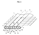
FIG. 3 is a perspective view of an optical fiber ribbon according to an alternative embodiment of the present invention, which shows a cross section in part. - Exemplary embodiments of the present invention will be described hereinafter with reference to
FIGs. 1 through 3 . - Referring to
FIG. 1 , anoptical fiber ribbon 1 in accordance with an embodiment includes a plurality ofoptical fibers 3 running in parallel. Each of theoptical fibers 3 may be either a bare fiber or a fiber cord, and the whole of them is covered with ablanket sheath 5 so as to form a tape. As theoptical fibers 3 form a single layer, theoptical fiber ribbon 1 is relatively thin and therefore preferably applicable to space-saving uses. Of course, theoptical fibers 3 may be made to form a plurality of layers. Further, for the purpose of distinction of theoptical fibers 3, these surfaces or any faces may be colored. - On the
blanket sheath 5, at any one or more intermediates amongoptical fibers 3,concavities 5A are formed. Each of theconcavities 5A is formed over the entire length in its longitudinal direction of theblanket sheath 5. Respectively along theconcavities 5A,slits 7 are formed. Theslits 7 are arranged in series at regular intervals B along the concavities and penetrate theblanket sheath 5 in its thickness direction so as to allow atool 13 to be inserted therein. Each of theconcavities 5A may have a neck portion substantially parallel to its bottom portion. - While the
slits 7 give structural separation betweenpartial ribbons portions 9 which are theconcavities 5A but theslits 7 establish junction between thepartial ribbons - In the embodiment shown in
FIG. 1 , anoptical fiber ribbon 1 contains eightoptical fibers 3. Whennumbers # 1 through #8 are attached to theseoptical fibers 3 one by one from one end thereof, aconcavity 5A is formed in an intermediate between the #4optical fiber 3 and the #5optical fiber 3. By using thisconcavity 5A and theslits 7 formed along theconcavity 5A, theblanket sheath 5 can split so that theoptical fiber ribbon 1 can be divided into apartial ribbon 1A including the #1 through #4optical fibers 3 and apartial ribbon 1B including the #5 through #8optical fibers 3. -
FIG. 1 exemplarily shows that the #4 and #5optical fibers 3 are to some extent apart from each other. Although such a structure is preferable in view of easiness of forming theslits 7 and suppression of curvature of theoptical fibers 3, the #4 and #5optical fibers 3 may be modified to mutually adjoin. Further, the number of theoptical fibers 3, and the position and the number of theconcavities 5A are also not limited to those described above. - The work of separating the
optical fiber ribbon 1 can be executed without any tool, however, anyproper tool 13 may be used for the purpose of preventing theoptical fiber 3 from bending. As thetool 13, any versatile member such as a wire rod having a round, or somehow differently shaped, cross section. Thetool 13 is inserted into any of theslits 7 and then moved along theconcavity 5A, thereby splitting theblanket sheath 5 along asplitting line 11 and then separating theoptical fiber ribbon 1. - When the
tool 13 is inserted into one of theslits 7, the radius of curvature of the relatedoptical fiber 3 decreases (flexure thereof increases). If the radius of curvature falls below an allowable radius of curvature, the transmission loss increases to exceed an allowable limit. Thus theslit 7 is so dimensioned that the radius of curvature of the optical fiber resulting from widening of the slit by thetool 13 is kept larger than the allowable radius of curvature as described hereinafter. More specifically, as exemplarily shown inFIG. 2 , thetool 13 inserted into one of theslit 7 widens theslit 7 so that flexure is induced on one of theoptical fiber 3 adjacent to theslit 7 at issue. As this flexure can be approximated by an arc, when a radius of curvature by this flexure is r, a width of the tool 13 (or a diameter if its cross section is round) is X, and a length of theslit 7 prior to insertion of thetool 13 is A, a relation among them is represented by the following equation.
- Therefore, to prevent the radius of curvature r from falling below the allowable radius of curvature R, the length A of the
slit 7 can be determined on the basis of the following inequality.
- Here, Y represents a lower limit of the length of the
slit 7 so as not to fall below the allowable radius of curvature R. As the allowable radius of curvature R is typically 30mm for instance, the length A of theslit 7 can be determined on the basis of the following inequality. (seeFIG. 2 )
- Then the radius of curvature of the
optical fiber 3 is assured to be larger than 30mm that is the allowable radius of curvature, therefore increase in transmission loss of the optical fiber led from separation of theoptical fiber ribbon 1 can be sufficiently suppressed. - At a time of intermediate branching of an optical fiber cable such as an SZ-type optical fiber cable, it is required to peel off a sheath of the cable over the length of 500mm. The
concavity 5A preferably has at least one junction portion 9 (a portion not aslit 7 in theconcavity 5A). - Taking the aforementioned matters into consideration, provided that a lower limit length of the
list 7 is Y, the length A of theslit 7 preferably satisfies the following inequalities.



- Further, when a thickness of the
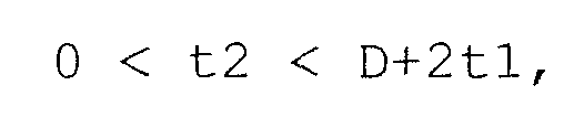
blanket sheath 5 from theoptical fiber 3 to a surface thereof is t1 and a thickness of theconcavity 5A is t2, t2 is preferably within a range of 0 < t2 < D+2t1. As being capable of splitting with a relatively small force, theconcavity 5A structured in this way effectively prevents application of an excessive force to theoptical fiber 3. More specifically, as flexure of theoptical fiber 3 is suppressed, increase in transmission loss is suppressed. - Although in the above arguments a wire rod having a round cross section is exemplified as the
tool 13, of course any tools of various shapes such as a sheet or a square pillar having a width X can be used. - As being understood from the above explanation, the number of optical fibers is arbitrary in the present embodiment of the present invention and a concavity including slits may be formed at any intermediate between any pair of the optical fibers. Further the number of concavities is also arbitrary. Further the shape of the concavity may be formed in a shape having a roughly V-shaped cross section instead of the shape shown in
FIG. 1 . As an example in such a structure, an embodiment shown inFIG. 3 is possible. In the embodiment shown inFIG. 3 , as each gap between adjacent optical fibers having a concavity is made as narrow as possible, the concavity is necessarily roughly V-shaped. Such anoptical fiber ribbon 1 including a plurality ofoptical fibers 3 is made to branch into a plurality ofribbons optical fibers 3. - Further, if the thickness t1 from the
optical fiber 3 to the surface of theblanket sheath 5 is in a range of 0 < t1 ≤ 0.025mm, the plurality ofribbons optical fibers 3 are readily respectively made to branch into ribbons each including a singleoptical fiber 3. Still further, instead of the versatile tool, a tool for shearing disclosed in Japanese - Patent Application Laid-open No.
2006-030684 2006-030684 , may be used for instance. - To demonstrate effects served by the aforementioned embodiments, the following measurements have been carried out. More specifically, an
optical fiber ribbon 1 containing eightoptical fibers 3 shown inFIG. 1 has been produced, separated intooptical fiber ribbons optical fibers 3, and further respectively separated into optical fiber ribbons each including only one of theoptical fibers 3, and then change of transmission loss is measured at each occasion of separation. Aconcavity 5A is formed at an intermediate between a #4 optical fiber and a #5 optical fiber, and slits 7 are formed to be arranged in series at regular intervals B along theconcavity 5A. - Here, a single-mode optical fiber (SMF) regulated in JIS-C6835 or ITUT-G652 and an SR10 optical fiber in conformity to ITUT-G652B are applied to the
optical fiber 3. An optical fiber of an SR10 equivalence is an optical fiber that has transmission of 0.50dB or less in regard to light of 1.550µm in wavelength when the fiber is bent to make 10 turns with a bending diameter Φ of 20mm. - The length A of the
slit 7 is 72mm and the interval B is 8mm. More specifically, A+B is 80mm and A/(A+B) is 0.9. Given that a wire rod of 0.2mm in diameter is used as a tool, the aforementioned condition in which


- Table 1 summarizes measurement results in which transmission loss change in a case where the
optical fiber ribbon 1 is separated into twooptical fiber ribbons [Table 1] Loss change at a time of separation
8 cores -> 4 coresTOOL FOR SEPARATION TYPE OF OPTICAL FIBER APPLIED TO RIBBON TOOL USING WIRE ROD TOOL BY SHEARING SMF ○ ○ SR10 equivalence ○ ○ ○: Loss change at a time of separation is 1dB or less.
△: Loss change at a time of separation is 1dB or larger (separation is possible).
X: separation is impossible. - As being understood from Table 1, in any optical fibers, and in any tools, changes in transmission loss are 1dB or less. Thus degradation of transmission properties is suppressed. Further in any case, the work of intermediate post-branching can be easily carried out.
- Table 2 summarizes measurement results in which transmission loss change in a case where the separated
optical fiber ribbons [Table 2] Loss change at a time of separation
4 cores -> single coreTOOL FOR SEPARATION TYPE OF OPTICAL FIBER APPLIED TO RIBBON TOOL USING WIRE ROD TOOL WITH FILE TOOL USING A PLURALITY OF SMALL PROJECTIONS SMF △ △ △ SR10 equivalence ○ ○ ○ ○: Loss change at a time of separation is 1dB or less.
△: Loss change at a time of separation is 1dB or larger (separation is possible).
X: separation is impossible. - As being understood from Table 2, in a case where the optical fiber of SMF is used, change in transmission loss is 1dB or larger even if any tools are used, but separation is possible. In a case where the optical fiber of the SR equivalence is used, as change in transmission loss is 1dB or less even if any tools are used, degradation of transmission properties induced by bending is sufficiently suppressed and further the work of intermediate post-branching can be very easily carried out.
- The
optical fiber ribbon 1 provides the following effects. More specifically, as it has a concavity including slits having a proper length A, bending of the optical fibers is suppressed when a tool for branching is inserted into any of the slits, thereby suppressing increase in transmission loss. By moving the tool along the concavity, the concavity splits and thus theoptical fiber ribbon 1 easily becomes capable of branching. - The
blanket sheath 5 can be produced only from one layer of a resin. This leads to a possibility for production of a very thinoptical fiber ribbon 1 can be produced. A very thinoptical fiber ribbon 1 is not only space-saving but also does facilitate the work of branching. - Because the
optical fiber ribbon 1 has a structure or shape similar to that of a conventional multi-core optical fiber ribbon, it can be used compatibly with the conventional multi-core optical fiber ribbon, apart from differences in properties such as easiness of branching. - Although the invention has been described above by reference to certain exemplary embodiments of the invention, the invention is not limited to the exemplary embodiments described above. Modifications and variations of the embodiments described above will occur to those skilled in the art, in light of the above teachings.
- An optical fiber ribbon which is readily made to branch by means of versatile tools with suppressing transmission loss by bending and a method for making the optical fiber ribbon branch are provided.
Claims (5)
- An optical fiber ribbon capable of branching by means of a tool having a width (X), the optical fiber ribbon comprising:a plurality of optical fibers running in parallel, each of the optical fibers having an allowable radius of curvature;a blanket sheath totally covering the plurality of the optical fibers;one or more concavities formed at any one or more intermediates among the optical fibers; andslits respectively arranged in series at a regular interval along the concavities, the slits penetrating the blanket sheath and allowing the tool to be inserted and the blanket sheath to split by means of movement of the tool along the concavities, each of the slits having a length prior to insertion of the tool so determined that flexures of the optical fibers induced by the tool widening the slits do not exceed the allowable radius of curvature.
- The optical fiber ribbon of claim 1, wherein each of the optical fibers has an outer diameter (D), the blanket sheath has a thickness (t1) from the respective optical fibers to a surface, each of the concavities has a thickness (t2), and a length (A), the allowable redius of curvature (R), and the intervals (B) satisfy:




wherein Y is a lower limit length of the slits. - The optical fiber ribbon of claim 1, wherein each of the optical fibers has an outer diameter (D), the blanket sheath has a thickness (t1) from the respective optical fibers to a surface, each of the concavities has a thickness (t2), and a length (A), and the intervals (B) satisfy:


- The optical fiber ribbon of claim 2, wherein the thickness (t1) satisfies 0 < t1 ≤ 0.025mm.
- A method for making an optical fiber ribbon branch, the optical fiber ribbon comprising a plurality of optical fibers running in parallel, each of the optical fibers having an allowable radius of curvature; a blanket sheath totally covering the plurality of the optical fibers; one or more concavities formed at any one or more intermediates among the optical fibers; and slits penetrating the blanket sheath, the method comprising:inserting a tool having a width so determined that flexures of the optical fibers induced by the tool widening the slits do not exceed the allowable radius of curvature into one selected from the slits; andmoving the tool along the concavities to split the blanket sheath.
Applications Claiming Priority (2)
| Application Number | Priority Date | Filing Date | Title |
|---|---|---|---|
| JP2008001278A JP2009163045A (en) | 2008-01-08 | 2008-01-08 | Optical fiber ribbon and its dividing method |
| PCT/JP2008/073594 WO2009087911A1 (en) | 2008-01-08 | 2008-12-25 | Optical fiber tape core wire able to be branched and branching method therefor |
Publications (3)
| Publication Number | Publication Date |
|---|---|
| EP2239608A1 true EP2239608A1 (en) | 2010-10-13 |
| EP2239608A4 EP2239608A4 (en) | 2013-05-29 |
| EP2239608B1 EP2239608B1 (en) | 2019-09-25 |
Family
ID=40853035
Family Applications (1)
| Application Number | Title | Priority Date | Filing Date |
|---|---|---|---|
| EP08869892.3A Active EP2239608B1 (en) | 2008-01-08 | 2008-12-25 | System consisting of a tool and an optical fiber ribbon able to be branched by the tool and related method for making fiber ribbon branch |
Country Status (6)
| Country | Link |
|---|---|
| US (1) | US8412014B2 (en) |
| EP (1) | EP2239608B1 (en) |
| JP (1) | JP2009163045A (en) |
| CN (1) | CN101910901A (en) |
| BR (1) | BRPI0821971A2 (en) |
| WO (1) | WO2009087911A1 (en) |
Cited By (2)
| Publication number | Priority date | Publication date | Assignee | Title |
|---|---|---|---|---|
| US9389382B2 (en) | 2014-06-03 | 2016-07-12 | Corning Optical Communications LLC | Fiber optic ribbon cable and ribbon |
| WO2017095541A1 (en) * | 2015-11-30 | 2017-06-08 | Corning Optical Communications LLC | Flexible optical fiber ribbon with ribbon body flexibility recesses |
Families Citing this family (29)
| Publication number | Priority date | Publication date | Assignee | Title |
|---|---|---|---|---|
| JP4748539B2 (en) * | 2008-03-29 | 2011-08-17 | 古河電気工業株式会社 | Apparatus and method for measuring the fusion force between pipes |
| JP5697011B2 (en) * | 2010-02-16 | 2015-04-08 | 古河電気工業株式会社 | Optical fiber cable and method of forming optical fiber cable |
| JP5564026B2 (en) * | 2011-10-18 | 2014-07-30 | 株式会社フジクラ | Optical fiber tape core and optical fiber cable storing the optical fiber core |
| JP5615854B2 (en) * | 2012-01-31 | 2014-10-29 | 日本電信電話株式会社 | Optical fiber tape and optical fiber cable |
| JP2013205501A (en) * | 2012-03-27 | 2013-10-07 | Sumitomo Electric Ind Ltd | Optical fiber ribbon and optical fiber cable including optical fiber ribbon |
| CN103376521B (en) * | 2012-04-24 | 2015-06-03 | 上海裕荣光电科技股份有限公司 | Device optical fiber band and manufacturing method thereof |
| CA3178019A1 (en) | 2012-05-02 | 2013-11-07 | Afl Telecommunications Llc | Round and small diameter optical cables with a ribbon-like optical fiber structure |
| US20150185428A1 (en) * | 2012-08-09 | 2015-07-02 | Fujikura Ltd. | Binder fiber for optical fiber unit |
| JP2015108756A (en) * | 2013-12-05 | 2015-06-11 | 住友電気工業株式会社 | Optical fiber unit, optical fiber cable, and manufacturing method of optical fiber unit |
| JP6132438B2 (en) * | 2014-03-19 | 2017-05-24 | コマツNtc株式会社 | Cutting method with single wire type wire saw and single wire type wire saw |
| JP6639773B2 (en) * | 2014-09-17 | 2020-02-05 | 古河電気工業株式会社 | Loose tube optical fiber unit |
| JP2016075814A (en) * | 2014-10-07 | 2016-05-12 | 住友電気工業株式会社 | Fiber optic cable |
| JP6592909B2 (en) * | 2015-02-03 | 2019-10-23 | 住友電気工業株式会社 | Optical cable and manufacturing method thereof |
| CN104898220A (en) * | 2015-05-06 | 2015-09-09 | 深圳市特发信息股份有限公司 | Multilayer optical fiber ribbon |
| EP3329311A4 (en) * | 2015-07-31 | 2019-03-27 | Corning Optical Communications LLC | FIBER OPTIC ROLLER TAPE |
| JP6106253B1 (en) * | 2015-12-04 | 2017-03-29 | 株式会社フジクラ | OPTICAL FIBER TAPE, OPTICAL FIBER TAPE MANUFACTURING METHOD, AND ULTRAVIOLET-CURABLE RESIN COMPOSITION USED FOR FORMING INTERCONNECTION OF INTERNAL FIXED OPTICAL FIBER TAPE |
| AU2016386157A1 (en) * | 2016-01-13 | 2018-07-19 | Sumitomo Electric Industries, Ltd. | Intermittent-connection-type optical fiber tape core, optical cable, and method for manufacturing intermittent-connection-type optical fiber tape core |
| US10989888B2 (en) * | 2016-02-02 | 2021-04-27 | Ofs Fitel, Llc | Flexible ribbon structure and method for making |
| CN105666787B (en) * | 2016-04-12 | 2018-03-09 | 深圳市特发信息股份有限公司 | A kind of multilayer fibers band mould |
| MX2019004832A (en) * | 2016-12-01 | 2019-06-20 | Commscope Technologies Llc | Fiber ribbonizer. |
| JP7020049B2 (en) * | 2017-10-16 | 2022-02-16 | 住友電気工業株式会社 | Method for manufacturing dies and optical fiber tape core wires |
| US20190219783A1 (en) * | 2018-01-12 | 2019-07-18 | Ofs Fitel, Llc | Multi-fiber unit tube optical fiber microcable incorporating rollable optical fibers ribbons |
| US11209605B2 (en) | 2019-04-12 | 2021-12-28 | Sumitomo Electric Industries, Ltd. | Optical fiber ribbon, die, and method of manufacturing optical fiber ribbon |
| US11579387B2 (en) * | 2019-08-14 | 2023-02-14 | Sterlite Technologies Limited | Arrangement of optical fibre ribbon stack and an optical fibre ribbon thereof |
| WO2022054940A1 (en) * | 2020-09-14 | 2022-03-17 | 住友電気工業株式会社 | Optical fiber ribbon and method for manufacturing optical fiber ribbon |
| WO2022075364A1 (en) * | 2020-10-07 | 2022-04-14 | 住友電気工業株式会社 | Optical fiber ribbon, die, and manufacturing method for optical fiber ribbon |
| US11442238B2 (en) * | 2020-12-22 | 2022-09-13 | Prysmian S.P.A. | Optical-fiber ribbon with spaced optical-fiber units |
| US11780103B2 (en) | 2021-02-11 | 2023-10-10 | Prysmian S.P.A. | Fiber ribbon separation tool |
| JP2022183873A (en) * | 2021-05-31 | 2022-12-13 | 住友電気工業株式会社 | fiber optic ribbon |
Family Cites Families (18)
| Publication number | Priority date | Publication date | Assignee | Title |
|---|---|---|---|---|
| JPS5922404U (en) | 1982-08-04 | 1984-02-10 | 日本電信電話株式会社 | optical fiber unit |
| JP2573632B2 (en) * | 1987-11-26 | 1997-01-22 | 住友電気工業株式会社 | Tape-type optical fiber manufacturing equipment |
| JPH0246411A (en) | 1988-08-08 | 1990-02-15 | Sumitomo Electric Ind Ltd | Method of branching tape-like coated optical fiber |
| JP2932509B2 (en) * | 1989-07-13 | 1999-08-09 | 住友電気工業株式会社 | Optical fiber ribbon splitting tool |
| US4952020A (en) * | 1989-08-09 | 1990-08-28 | Amp Incorporated | Ribbon cable with optical fibers and electrical conductors |
| JPH07306320A (en) * | 1994-05-11 | 1995-11-21 | Sumitomo Electric Ind Ltd | Separator for optical fiber ribbon |
| JP3645625B2 (en) | 1995-09-13 | 2005-05-11 | オリンパス株式会社 | Microscope automatic focus detection method, microscope automatic focus detection device, and microscope using the same |
| JPH11183768A (en) * | 1997-12-22 | 1999-07-09 | Yazaki Corp | Split type optical fiber ribbon and manufacturing method thereof |
| JP2003279756A (en) * | 2002-03-26 | 2003-10-02 | Sumitomo Electric Ind Ltd | How to branch optical fiber ribbon |
| CA2475970A1 (en) * | 2002-05-28 | 2003-12-04 | Sumitomo Electric Industries, Ltd. | Optical fiber tape core |
| JP4055000B2 (en) * | 2003-08-11 | 2008-03-05 | 住友電気工業株式会社 | Optical fiber cable, optical fiber cable manufacturing method, and optical fiber cable manufacturing apparatus |
| JP2005249977A (en) * | 2004-03-02 | 2005-09-15 | Sumitomo Electric Ind Ltd | Fiber optic cable |
| JP2005292518A (en) * | 2004-03-31 | 2005-10-20 | Sumitomo Electric Ind Ltd | Optical fiber tape unit and optical fiber cable |
| US7039282B2 (en) * | 2004-06-30 | 2006-05-02 | Corning Cable Systems Llc | Optical fiber array with an intermittent profile and method for manufacturing the same |
| JP4115433B2 (en) | 2004-07-16 | 2008-07-09 | 古河電気工業株式会社 | Optical fiber ribbon separation method and separation tool |
| JP4084363B2 (en) * | 2005-02-25 | 2008-04-30 | 古河電気工業株式会社 | Separation method of optical fiber ribbon and separation tool set |
| JP2006267275A (en) * | 2005-03-22 | 2006-10-05 | Fujikura Ltd | Optical fiber core separation tool |
| JP2005352510A (en) | 2005-07-29 | 2005-12-22 | Sumitomo Electric Ind Ltd | Optical fiber tape unit and optical fiber cable |
-
2008
- 2008-01-08 JP JP2008001278A patent/JP2009163045A/en active Pending
- 2008-12-25 US US12/811,978 patent/US8412014B2/en active Active
- 2008-12-25 EP EP08869892.3A patent/EP2239608B1/en active Active
- 2008-12-25 WO PCT/JP2008/073594 patent/WO2009087911A1/en not_active Ceased
- 2008-12-25 BR BRPI0821971-0A patent/BRPI0821971A2/en not_active Application Discontinuation
- 2008-12-25 CN CN2008801243573A patent/CN101910901A/en active Pending
Cited By (4)
| Publication number | Priority date | Publication date | Assignee | Title |
|---|---|---|---|---|
| US9389382B2 (en) | 2014-06-03 | 2016-07-12 | Corning Optical Communications LLC | Fiber optic ribbon cable and ribbon |
| WO2017095541A1 (en) * | 2015-11-30 | 2017-06-08 | Corning Optical Communications LLC | Flexible optical fiber ribbon with ribbon body flexibility recesses |
| US10330876B2 (en) | 2015-11-30 | 2019-06-25 | Corning Optical Communications LLC | Flexible optical fiber ribbon with ribbon body flexibility recesses |
| US10725256B2 (en) | 2015-11-30 | 2020-07-28 | Corning Optical Communications LLC | Flexible optical fiber ribbon with ribbon body flexibility recesses |
Also Published As
| Publication number | Publication date |
|---|---|
| WO2009087911A1 (en) | 2009-07-16 |
| EP2239608A4 (en) | 2013-05-29 |
| JP2009163045A (en) | 2009-07-23 |
| US20100296781A1 (en) | 2010-11-25 |
| CN101910901A (en) | 2010-12-08 |
| BRPI0821971A2 (en) | 2015-06-23 |
| EP2239608B1 (en) | 2019-09-25 |
| US8412014B2 (en) | 2013-04-02 |
Similar Documents
| Publication | Publication Date | Title |
|---|---|---|
| EP2239608B1 (en) | System consisting of a tool and an optical fiber ribbon able to be branched by the tool and related method for making fiber ribbon branch | |
| EP3330760B1 (en) | Optical fiber cable | |
| EP2175295A1 (en) | Optical fiber cable and optical cable | |
| US20040247265A1 (en) | Branching method for an optical fiber cable | |
| EP3812815B1 (en) | Optical fiber cable | |
| WO2010106858A1 (en) | Optical fiber cable | |
| US12204141B2 (en) | Optical fiber bundle structure, optical connector, optical fiber connection structure, and method of manufacturing optical fiber bundle structure | |
| JP4974165B2 (en) | Manufacturing method of optical fiber connection structure | |
| JP4980841B2 (en) | Optical fiber ribbon and its dividing method | |
| EP4027180B1 (en) | Optical fiber ribbon, optical fiber cable, and connector-equipped optical fiber cord | |
| EP4414762A1 (en) | Optical fiber ribbon | |
| JP6365459B2 (en) | Optical fiber ribbon, optical fiber cable and optical fiber cord | |
| CA2571041A1 (en) | Optical fiber array with an intermittent profile and method for manufacturing the same | |
| JP4665535B2 (en) | Fiber optic cable | |
| HK1147806A (en) | Optical fiber tape core wire able to be branched and branching method thereof | |
| JP2006153930A (en) | Self-supporting optical fiber cable | |
| JP2005249977A (en) | Fiber optic cable | |
| JP2006154448A (en) | Optical fiber cord | |
| JP4258653B2 (en) | Optical fiber cable slot and optical fiber cable | |
| KR200184180Y1 (en) | Slot type optical cable for guiding ribbon multi-core fiber | |
| JP4252588B2 (en) | Fiber optic cable | |
| JP2003295013A (en) | Single fiber separated type optical fiber tape | |
| JP2012053107A (en) | Optical fiber cable | |
| JP2009265525A (en) | Optical fiber cable | |
| HK1254082B (en) | Optical fiber cable |
Legal Events
| Date | Code | Title | Description |
|---|---|---|---|
| PUAI | Public reference made under article 153(3) epc to a published international application that has entered the european phase |
Free format text: ORIGINAL CODE: 0009012 |
|
| 17P | Request for examination filed |
Effective date: 20100804 |
|
| AK | Designated contracting states |
Kind code of ref document: A1 Designated state(s): AT BE BG CH CY CZ DE DK EE ES FI FR GB GR HR HU IE IS IT LI LT LU LV MC MT NL NO PL PT RO SE SI SK TR |
|
| AX | Request for extension of the european patent |
Extension state: AL BA MK RS |
|
| DAX | Request for extension of the european patent (deleted) | ||
| A4 | Supplementary search report drawn up and despatched |
Effective date: 20130425 |
|
| RIC1 | Information provided on ipc code assigned before grant |
Ipc: G02B 6/44 20060101AFI20130419BHEP |
|
| STAA | Information on the status of an ep patent application or granted ep patent |
Free format text: STATUS: EXAMINATION IS IN PROGRESS |
|
| 17Q | First examination report despatched |
Effective date: 20180307 |
|
| GRAP | Despatch of communication of intention to grant a patent |
Free format text: ORIGINAL CODE: EPIDOSNIGR1 |
|
| STAA | Information on the status of an ep patent application or granted ep patent |
Free format text: STATUS: GRANT OF PATENT IS INTENDED |
|
| INTG | Intention to grant announced |
Effective date: 20190523 |
|
| RIN1 | Information on inventor provided before grant (corrected) |
Inventor name: SATO, YUKIKO Inventor name: OKADA, NAOKI Inventor name: SANO, KEIKO |
|
| GRAS | Grant fee paid |
Free format text: ORIGINAL CODE: EPIDOSNIGR3 |
|
| GRAA | (expected) grant |
Free format text: ORIGINAL CODE: 0009210 |
|
| STAA | Information on the status of an ep patent application or granted ep patent |
Free format text: STATUS: THE PATENT HAS BEEN GRANTED |
|
| AK | Designated contracting states |
Kind code of ref document: B1 Designated state(s): AT BE BG CH CY CZ DE DK EE ES FI FR GB GR HR HU IE IS IT LI LT LU LV MC MT NL NO PL PT RO SE SI SK TR |
|
| REG | Reference to a national code |
Ref country code: GB Ref legal event code: FG4D |
|
| REG | Reference to a national code |
Ref country code: CH Ref legal event code: EP |
|
| REG | Reference to a national code |
Ref country code: AT Ref legal event code: REF Ref document number: 1184370 Country of ref document: AT Kind code of ref document: T Effective date: 20191015 |
|
| REG | Reference to a national code |
Ref country code: IE Ref legal event code: FG4D |
|
| REG | Reference to a national code |
Ref country code: DE Ref legal event code: R096 Ref document number: 602008061295 Country of ref document: DE |
|
| REG | Reference to a national code |
Ref country code: SE Ref legal event code: TRGR |
|
| REG | Reference to a national code |
Ref country code: NL Ref legal event code: FP |
|
| PG25 | Lapsed in a contracting state [announced via postgrant information from national office to epo] |
Ref country code: BG Free format text: LAPSE BECAUSE OF FAILURE TO SUBMIT A TRANSLATION OF THE DESCRIPTION OR TO PAY THE FEE WITHIN THE PRESCRIBED TIME-LIMIT Effective date: 20191225 Ref country code: NO Free format text: LAPSE BECAUSE OF FAILURE TO SUBMIT A TRANSLATION OF THE DESCRIPTION OR TO PAY THE FEE WITHIN THE PRESCRIBED TIME-LIMIT Effective date: 20191225 Ref country code: LT Free format text: LAPSE BECAUSE OF FAILURE TO SUBMIT A TRANSLATION OF THE DESCRIPTION OR TO PAY THE FEE WITHIN THE PRESCRIBED TIME-LIMIT Effective date: 20190925 Ref country code: HR Free format text: LAPSE BECAUSE OF FAILURE TO SUBMIT A TRANSLATION OF THE DESCRIPTION OR TO PAY THE FEE WITHIN THE PRESCRIBED TIME-LIMIT Effective date: 20190925 |
|
| REG | Reference to a national code |
Ref country code: LT Ref legal event code: MG4D |
|
| PG25 | Lapsed in a contracting state [announced via postgrant information from national office to epo] |
Ref country code: LV Free format text: LAPSE BECAUSE OF FAILURE TO SUBMIT A TRANSLATION OF THE DESCRIPTION OR TO PAY THE FEE WITHIN THE PRESCRIBED TIME-LIMIT Effective date: 20190925 Ref country code: GR Free format text: LAPSE BECAUSE OF FAILURE TO SUBMIT A TRANSLATION OF THE DESCRIPTION OR TO PAY THE FEE WITHIN THE PRESCRIBED TIME-LIMIT Effective date: 20191226 |
|
| REG | Reference to a national code |
Ref country code: AT Ref legal event code: MK05 Ref document number: 1184370 Country of ref document: AT Kind code of ref document: T Effective date: 20190925 |
|
| PG25 | Lapsed in a contracting state [announced via postgrant information from national office to epo] |
Ref country code: ES Free format text: LAPSE BECAUSE OF FAILURE TO SUBMIT A TRANSLATION OF THE DESCRIPTION OR TO PAY THE FEE WITHIN THE PRESCRIBED TIME-LIMIT Effective date: 20190925 Ref country code: PT Free format text: LAPSE BECAUSE OF FAILURE TO SUBMIT A TRANSLATION OF THE DESCRIPTION OR TO PAY THE FEE WITHIN THE PRESCRIBED TIME-LIMIT Effective date: 20200127 Ref country code: AT Free format text: LAPSE BECAUSE OF FAILURE TO SUBMIT A TRANSLATION OF THE DESCRIPTION OR TO PAY THE FEE WITHIN THE PRESCRIBED TIME-LIMIT Effective date: 20190925 Ref country code: RO Free format text: LAPSE BECAUSE OF FAILURE TO SUBMIT A TRANSLATION OF THE DESCRIPTION OR TO PAY THE FEE WITHIN THE PRESCRIBED TIME-LIMIT Effective date: 20190925 Ref country code: EE Free format text: LAPSE BECAUSE OF FAILURE TO SUBMIT A TRANSLATION OF THE DESCRIPTION OR TO PAY THE FEE WITHIN THE PRESCRIBED TIME-LIMIT Effective date: 20190925 Ref country code: PL Free format text: LAPSE BECAUSE OF FAILURE TO SUBMIT A TRANSLATION OF THE DESCRIPTION OR TO PAY THE FEE WITHIN THE PRESCRIBED TIME-LIMIT Effective date: 20190925 |
|
| PG25 | Lapsed in a contracting state [announced via postgrant information from national office to epo] |
Ref country code: CZ Free format text: LAPSE BECAUSE OF FAILURE TO SUBMIT A TRANSLATION OF THE DESCRIPTION OR TO PAY THE FEE WITHIN THE PRESCRIBED TIME-LIMIT Effective date: 20190925 Ref country code: SK Free format text: LAPSE BECAUSE OF FAILURE TO SUBMIT A TRANSLATION OF THE DESCRIPTION OR TO PAY THE FEE WITHIN THE PRESCRIBED TIME-LIMIT Effective date: 20190925 Ref country code: IS Free format text: LAPSE BECAUSE OF FAILURE TO SUBMIT A TRANSLATION OF THE DESCRIPTION OR TO PAY THE FEE WITHIN THE PRESCRIBED TIME-LIMIT Effective date: 20200224 |
|
| REG | Reference to a national code |
Ref country code: DE Ref legal event code: R097 Ref document number: 602008061295 Country of ref document: DE |
|
| PG2D | Information on lapse in contracting state deleted |
Ref country code: IS |
|
| PG25 | Lapsed in a contracting state [announced via postgrant information from national office to epo] |
Ref country code: DK Free format text: LAPSE BECAUSE OF FAILURE TO SUBMIT A TRANSLATION OF THE DESCRIPTION OR TO PAY THE FEE WITHIN THE PRESCRIBED TIME-LIMIT Effective date: 20190925 Ref country code: IS Free format text: LAPSE BECAUSE OF FAILURE TO SUBMIT A TRANSLATION OF THE DESCRIPTION OR TO PAY THE FEE WITHIN THE PRESCRIBED TIME-LIMIT Effective date: 20200126 |
|
| PLBE | No opposition filed within time limit |
Free format text: ORIGINAL CODE: 0009261 |
|
| REG | Reference to a national code |
Ref country code: CH Ref legal event code: PL |
|
| STAA | Information on the status of an ep patent application or granted ep patent |
Free format text: STATUS: NO OPPOSITION FILED WITHIN TIME LIMIT |
|
| REG | Reference to a national code |
Ref country code: BE Ref legal event code: MM Effective date: 20191231 |
|
| PG25 | Lapsed in a contracting state [announced via postgrant information from national office to epo] |
Ref country code: MC Free format text: LAPSE BECAUSE OF FAILURE TO SUBMIT A TRANSLATION OF THE DESCRIPTION OR TO PAY THE FEE WITHIN THE PRESCRIBED TIME-LIMIT Effective date: 20190925 |
|
| 26N | No opposition filed |
Effective date: 20200626 |
|
| PG25 | Lapsed in a contracting state [announced via postgrant information from national office to epo] |
Ref country code: IE Free format text: LAPSE BECAUSE OF NON-PAYMENT OF DUE FEES Effective date: 20191225 Ref country code: LU Free format text: LAPSE BECAUSE OF NON-PAYMENT OF DUE FEES Effective date: 20191225 |
|
| PG25 | Lapsed in a contracting state [announced via postgrant information from national office to epo] |
Ref country code: SI Free format text: LAPSE BECAUSE OF FAILURE TO SUBMIT A TRANSLATION OF THE DESCRIPTION OR TO PAY THE FEE WITHIN THE PRESCRIBED TIME-LIMIT Effective date: 20190925 Ref country code: CH Free format text: LAPSE BECAUSE OF NON-PAYMENT OF DUE FEES Effective date: 20191231 Ref country code: LI Free format text: LAPSE BECAUSE OF NON-PAYMENT OF DUE FEES Effective date: 20191231 Ref country code: BE Free format text: LAPSE BECAUSE OF NON-PAYMENT OF DUE FEES Effective date: 20191231 |
|
| PG25 | Lapsed in a contracting state [announced via postgrant information from national office to epo] |
Ref country code: CY Free format text: LAPSE BECAUSE OF FAILURE TO SUBMIT A TRANSLATION OF THE DESCRIPTION OR TO PAY THE FEE WITHIN THE PRESCRIBED TIME-LIMIT Effective date: 20190925 |
|
| PG25 | Lapsed in a contracting state [announced via postgrant information from national office to epo] |
Ref country code: MT Free format text: LAPSE BECAUSE OF FAILURE TO SUBMIT A TRANSLATION OF THE DESCRIPTION OR TO PAY THE FEE WITHIN THE PRESCRIBED TIME-LIMIT Effective date: 20190925 Ref country code: HU Free format text: LAPSE BECAUSE OF FAILURE TO SUBMIT A TRANSLATION OF THE DESCRIPTION OR TO PAY THE FEE WITHIN THE PRESCRIBED TIME-LIMIT; INVALID AB INITIO Effective date: 20081225 |
|
| PG25 | Lapsed in a contracting state [announced via postgrant information from national office to epo] |
Ref country code: TR Free format text: LAPSE BECAUSE OF FAILURE TO SUBMIT A TRANSLATION OF THE DESCRIPTION OR TO PAY THE FEE WITHIN THE PRESCRIBED TIME-LIMIT Effective date: 20190925 |
|
| P01 | Opt-out of the competence of the unified patent court (upc) registered |
Effective date: 20230512 |
|
| PGFP | Annual fee paid to national office [announced via postgrant information from national office to epo] |
Ref country code: NL Payment date: 20251112 Year of fee payment: 18 |
|
| PGFP | Annual fee paid to national office [announced via postgrant information from national office to epo] |
Ref country code: DE Payment date: 20251028 Year of fee payment: 18 |
|
| PGFP | Annual fee paid to national office [announced via postgrant information from national office to epo] |
Ref country code: GB Payment date: 20251114 Year of fee payment: 18 |
|
| PGFP | Annual fee paid to national office [announced via postgrant information from national office to epo] |
Ref country code: IT Payment date: 20251121 Year of fee payment: 18 Ref country code: FI Payment date: 20251211 Year of fee payment: 18 |
|
| PGFP | Annual fee paid to national office [announced via postgrant information from national office to epo] |
Ref country code: FR Payment date: 20251110 Year of fee payment: 18 |
|
| PGFP | Annual fee paid to national office [announced via postgrant information from national office to epo] |
Ref country code: SE Payment date: 20251112 Year of fee payment: 18 |