EP2239466B1 - Pond pump units - Google Patents
Pond pump units Download PDFInfo
- Publication number
- EP2239466B1 EP2239466B1 EP10250035.2A EP10250035A EP2239466B1 EP 2239466 B1 EP2239466 B1 EP 2239466B1 EP 10250035 A EP10250035 A EP 10250035A EP 2239466 B1 EP2239466 B1 EP 2239466B1
- Authority
- EP
- European Patent Office
- Prior art keywords
- container
- pump unit
- pond
- pump
- unit
- Prior art date
- Legal status (The legal status is an assumption and is not a legal conclusion. Google has not performed a legal analysis and makes no representation as to the accuracy of the status listed.)
- Active
Links
Images

Classifications
-
- F—MECHANICAL ENGINEERING; LIGHTING; HEATING; WEAPONS; BLASTING
- F04—POSITIVE - DISPLACEMENT MACHINES FOR LIQUIDS; PUMPS FOR LIQUIDS OR ELASTIC FLUIDS
- F04D—NON-POSITIVE-DISPLACEMENT PUMPS
- F04D29/00—Details, component parts, or accessories
- F04D29/40—Casings; Connections of working fluid
- F04D29/406—Casings; Connections of working fluid especially adapted for liquid pumps
-
- A—HUMAN NECESSITIES
- A01—AGRICULTURE; FORESTRY; ANIMAL HUSBANDRY; HUNTING; TRAPPING; FISHING
- A01K—ANIMAL HUSBANDRY; AVICULTURE; APICULTURE; PISCICULTURE; FISHING; REARING OR BREEDING ANIMALS, NOT OTHERWISE PROVIDED FOR; NEW BREEDS OF ANIMALS
- A01K63/00—Receptacles for live fish, e.g. aquaria; Terraria
- A01K63/04—Arrangements for treating water specially adapted to receptacles for live fish
- A01K63/047—Liquid pumps for aquaria
-
- F—MECHANICAL ENGINEERING; LIGHTING; HEATING; WEAPONS; BLASTING
- F04—POSITIVE - DISPLACEMENT MACHINES FOR LIQUIDS; PUMPS FOR LIQUIDS OR ELASTIC FLUIDS
- F04D—NON-POSITIVE-DISPLACEMENT PUMPS
- F04D13/00—Pumping installations or systems
- F04D13/02—Units comprising pumps and their driving means
- F04D13/06—Units comprising pumps and their driving means the pump being electrically driven
- F04D13/08—Units comprising pumps and their driving means the pump being electrically driven for submerged use
- F04D13/086—Units comprising pumps and their driving means the pump being electrically driven for submerged use the pump and drive motor are both submerged
-
- F—MECHANICAL ENGINEERING; LIGHTING; HEATING; WEAPONS; BLASTING
- F04—POSITIVE - DISPLACEMENT MACHINES FOR LIQUIDS; PUMPS FOR LIQUIDS OR ELASTIC FLUIDS
- F04D—NON-POSITIVE-DISPLACEMENT PUMPS
- F04D29/00—Details, component parts, or accessories
- F04D29/60—Mounting; Assembling; Disassembling
- F04D29/605—Mounting; Assembling; Disassembling specially adapted for liquid pumps
-
- F—MECHANICAL ENGINEERING; LIGHTING; HEATING; WEAPONS; BLASTING
- F04—POSITIVE - DISPLACEMENT MACHINES FOR LIQUIDS; PUMPS FOR LIQUIDS OR ELASTIC FLUIDS
- F04D—NON-POSITIVE-DISPLACEMENT PUMPS
- F04D29/00—Details, component parts, or accessories
- F04D29/70—Suction grids; Strainers; Dust separation; Cleaning
- F04D29/708—Suction grids; Strainers; Dust separation; Cleaning specially for liquid pumps
Definitions
- This invention relates to pond pump units which can be used, for example, in a garden pond for pumping water in order that the water is, for example, fed to a fountain or drawn through or fed to a filter.
- US2007/183905 A1 describes a pond pump comprising a housing and an intake connector, wherein the intake connector is moveable such that the suction volume can be varied.
- US5004535 A describes a reverse osmosis water purification system comprising a support structure and arranged to facilitate manual transportation.
- EP1908961 A2 describes a pump comprising a housing, a pump device and a suction connection that opens out in two separate suction channels.
- a pond pump unit suitable to be disposed in a body of water and comprising a pump for pumping pond water, a container within which the pump is housable in use and a plurality of moveable auxiliary parts which are connected to, or connectable to: a) the pump, when housed in the container, and/or b) the container; the moveable auxiliary parts being moveable between one or more storage locations provided within the container and operative positions in which the moveable auxiliary parts are connected to: a) the pump, when housed in the container, and/or b) the container; such that the pump unit has a storage configuration in which each of the plurality of moveable auxiliary parts is housed within the container and an operational configuration in which each of the plurality of moveable auxiliary parts is in a respective operative position.
- the container can thus act both as an operative part of the pond pump unit when the unit is in use and as a storage container when the unit is not in use.
- the plurality of moveable auxiliary parts may be housed wholly within the container when the pond pump unit is in the storage configuration.
- the pump unit can be considered to have a storage configuration envelope, that is, a boundary defined by all of the outermost portions of the pump unit, when the pump unit is in the storage configuration.
- At least one of the moveable auxiliary parts when in its operative position, may be disposed outside of the container, and/or project outside of the storage configuration envelope of the pump unit.
- At least one of the moveable auxiliary parts may be stored within the container without being attached thereto and may be removable as a completely independent part from the container. Such a part may then be connected to the container and/or pump for use.
- the container may also be used to house other parts that may be used with the pump unit without being connected directly or indirectly to the unit.
- the container may comprise two parts which are moveable relative to one another between a closed position and an open position which allows access to the interior of the container to be obtained.
- the two parts of the container may be hingedly connected to one another.
- the container may be a cage which is arranged as a mechanical filter capable of filtering at least some of the water drawn into the pump unit in use.
- the pond pump unit may comprise a handle.
- the handle may be formed integrally with the container.
- the moveable auxiliary parts may comprise any one of, or any combination of: a power cable; outlet accessories - for example, an outlet hose connector; inlet accessories - for example, an inlet hose connector; a ball joint connector; fountain accessories; and a removable filter.
- the outlet accessories typically will be arranged for connection (directly, or indirectly) to an outlet of the pump.
- the inlet accessories typically will be arranged for connection (directly, or indirectly) to an inlet of the pump.
- the removable filter may be a clip in filter.
- the removable filter may, for example, be a push fit with, a sliding fit with, or just loosely contained within a container.
- the removable filter may be a wildlife protection filter.
- the container is a cage the removable filter may be a finer filter than at least a portion of the mechanical filter formed by the cage.
- the removable filter may be arranged for location adjacent said portion of the mechanical filter formed by the cage, when the unit is in use.
- the unit may be arranged to be operated selectively in one of at least two different orientations.
- the unit thus may be arranged to be stable if stood on one of at least two distinct faces of the container.
- an outlet of the pump unit may be opposite a face of the container on which the unit is stood. This can facilitate use of the pump unit as a fountain pump.
- the outlet of the pump unit may be adjacent a face of the container on which the unit is stood. This can facilitate use of the pump unit as a filter pump.
- the pump may be removable from the container. This can allow the container to be used as a filter unit with a remote pump.
- the remote pump may be the pump of the pump unit.
- the pump in use, may be disposed in a body of water in which the container resides or outside of that body of water.
- a pond filtering system comprising a pond pump unit as defined above wherein the pump is disposed outside of the container and connected thereto by hose, the container operates as a filter and the pump is arranged to draw water from the container, or deliver water to the container, via the hose.
- a packaged product comprising point of sale packaging and a pond pump unit as defined above wherein the pond pump unit is in its storage configuration and the point of sale packaging comprises a sleeve within which the pond pump unit is disposed.
- the point of sale packaging may consist only of said sleeve.
- the point of sale packaging may consist of only said sleeve plus shrink wrapping.
- the handle may be usable as a handle even when the unit is disposed in the point of sale packaging.
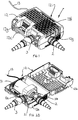
- FIGs 1 , 2A and 2B show a pond pump unit 1.
- the pond pump unit 1 comprises a pump 11 and a containing cage 12 which is shown in a closed and operative position in Figure 1 and in an open position in Figures 2A and 2B .
- Attached to the pump 11 is a power supply lead 13.
- Inlet accessories 2 and outlet accessories 3 are also connected to the pump 11 when it is in the operational configuration as shown in Figure 1 .
- the inlet accessories 2 are connected to an inlet 11b of the pump and the outlet accessories 3 are connected to an outlet 11a of the pump (see Figure 2B ).
- the accessories 2, 3 are arranged to allow a length of hose or tubing to be connected thereto, to carry water towards and away from the pump unit from, for example, another filter unit or a remote intake site and to, for example, a fountain or another remote outlet site.
- These inlet and outlet accessories 2, 3 are also shown connected to the pump 11 in Figure 2 where the cage 12 is open.
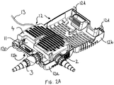
- a removable wildlife protection mechanical filter 4 is provided in the pond pump unit 1 and sits in the cage 12 when the pond pump unit is in the operational configuration. This wildlife protection filter 4 cannot be seen in Figure 1 but is shown in position in Figure 2A where the cage 12 is open. On the other hand the wildlife protection filter 4 is omitted from Figure 2B to allow the other internal components of the unit to be more clearly seen.
- the containing cage 12 has two parts 12a, 12b, which are hingedly mounted to one another to allow the cage to move between the closed position shown in Figure 1 and the open position shown in Figures 2A and 2B .
- the two cage parts 12a, 12b include appropriately moulded parts so that when the cage 12 is in the closed position shown in Figure 1 , an integral handle 12c is provided.
- one part of the cage 12b comprises clips 12d which are arranged to engage with respective engaging portions 12e of the other part 12a of the cage to releasably hold the cage 12 in the closed position shown in Figure 1 .
- the inlet accessory 2 mounted on the pump 11 includes an aperture 21 which provides a fluid flow path from the interior of the cage 12 into the inlet 11b of the pump 11. There is, of course, also a fluid flow path through the inlet accessory 2 into the inlet 11b of the pump 11.
- the cage 12 acts as a mechanical filter for filtering water drawn into the interior of the cage 12 and towards the aperture 21 by the pump 11 during operation.
- the cage 12 is provided with a plurality of apertures through which water can be drawn.
- these apertures are provided in one side face 12f (behind which is located the removable filter 4 when the unit is in its operative configuration and the user chooses to include the filter 4) and three end faces 12g of the cage 12.
- the pump unit 1 has two distinct stable orientations. One is the orientation shown in Figures 1 and 2 , where the unapertured side face 12h is being used as the face in contact with the ground and the other is an orientation where the unapertured edge face 12i is used as the surface to contact the ground. It is not essential but it is desirable for these surfaces 12h, 12i upon which the unit may be stood in use to be unapertured.
- the unit 1 in the orientation shown in Figures 1 and 2 , it is, for example, suitable for use as a filter pump.
- it is suitable for use, for example, as a fountain pump as the outlet 11a and outlet accessories 3 then point upwards.
- the removable filter 4 offers a finer mechanical filter than that provided by the cage 12. It is an optional component which can be used, for example, where it is desired to try to prevent small waterborne pond life from being sucked into the pump unit 1 through the apertured side wall of 12h of the cage 12.
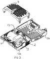
- FIG 3 shows the pump unit shown in Figures 1 and 2 with the cage 12 open and the power lead 13, inlet accessories 3 and outlet accessories 2 disposed in storage locations within the cage 12.
- the removable filter 4 is shown separately from the cage to help illustrate this feature but this component also has a storage location provided within the cage which, in this embodiment, corresponds to its operative position as shown in Figure 2A .
- the inlet and outlet accessories 2, 3 and power lead 13 are neatly housed within the cage 12 and do not project outside of it.
- the inlet and outlet accessories 2, 3 and power lead 13 do project outside of the cage 12 and outside of the storage configuration envelope of the pump unit 1.
- Figure 4 also shows a packaging sleeve 5 which is arranged to be slid over the pump unit 1 whilst in its storage configuration to provide a packaged product 6 as shown in Figure 5 .
- the point of sale packaging 5 thus consists only of a sleeve which wraps around the pump unit 1 when in its storage configuration. It will be appreciated of course that the provision of such a sleeve is optional as the cage itself 12 is doing the job of containing and safely storing all of the component parts of the pump unit 1.
- the unit may be (heat) shrink wrapped either over the sleeve, under the sleeve, or without the sleeve at all.
- This arrangement avoids the need for separate packaging such as a cardboard box which would normally be used to house a pump unit of the current type with the moveable auxiliary parts of the pump unit being stored within the box and not within the cage 1 as in the present arrangement.
- the sleeve 5 has a cut out 5a which allows the handle 12c of the cage 12 to be used even when the sleeve is in place to form the packaged product 6.
- the pump 11 is removable mounted in the cage 12. This means that the user can choose to remove the pump from the cage 12 and use the cage 12 as a filter unit.
- a remote pump which may be the pump 11 of the pump unit 1 may then be connected to the cage by suitable hose to form a filtering system.
- filters units made up using the present type of cage 12 might be used in one filtering system for a large pond.
- the remote pump might be disposed in the pond or outside of the pond in any such system.
Landscapes
- Engineering & Computer Science (AREA)
- Mechanical Engineering (AREA)
- General Engineering & Computer Science (AREA)
- Life Sciences & Earth Sciences (AREA)
- Environmental Sciences (AREA)
- Marine Sciences & Fisheries (AREA)
- Animal Husbandry (AREA)
- Biodiversity & Conservation Biology (AREA)
- Details Of Reciprocating Pumps (AREA)
- Structures Of Non-Positive Displacement Pumps (AREA)
Description
- This invention relates to pond pump units which can be used, for example, in a garden pond for pumping water in order that the water is, for example, fed to a fountain or drawn through or fed to a filter.
- With existing pond pump units there is a concern that excessive amounts of packaging are used for transport and/or sale. Furthermore, in some cases there can be limitations on the types of uses to which any one unit can be put.
- It would be desirable to alleviate one or more of these problems so as to allow more efficient manufacturing and less waste of packaging material.
-
US2007/183905 A1 describes a pond pump comprising a housing and an intake connector, wherein the intake connector is moveable such that the suction volume can be varied.US5004535 A describes a reverse osmosis water purification system comprising a support structure and arranged to facilitate manual transportation.EP1908961 A2 describes a pump comprising a housing, a pump device and a suction connection that opens out in two separate suction channels. - According to one aspect of the present invention there is provided a pond pump unit suitable to be disposed in a body of water and comprising a pump for pumping pond water, a container within which the pump is housable in use and a plurality of moveable auxiliary parts which are connected to, or connectable to: a) the pump, when housed in the container, and/or b) the container; the moveable auxiliary parts being moveable between one or more storage locations provided within the container and operative positions in which the moveable auxiliary parts are connected to: a) the pump, when housed in the container, and/or b) the container; such that the pump unit has a storage configuration in which each of the plurality of moveable auxiliary parts is housed within the container and an operational configuration in which each of the plurality of moveable auxiliary parts is in a respective operative position.
- The container can thus act both as an operative part of the pond pump unit when the unit is in use and as a storage container when the unit is not in use.
- The plurality of moveable auxiliary parts may be housed wholly within the container when the pond pump unit is in the storage configuration.
- The pump unit can be considered to have a storage configuration envelope, that is, a boundary defined by all of the outermost portions of the pump unit, when the pump unit is in the storage configuration.
- At least one of the moveable auxiliary parts, when in its operative position, may be disposed outside of the container, and/or project outside of the storage configuration envelope of the pump unit.
- At least one of the moveable auxiliary parts may be stored within the container without being attached thereto and may be removable as a completely independent part from the container. Such a part may then be connected to the container and/or pump for use.
- It will, of course, be appreciated that the container may also be used to house other parts that may be used with the pump unit without being connected directly or indirectly to the unit.
- The container may comprise two parts which are moveable relative to one another between a closed position and an open position which allows access to the interior of the container to be obtained. The two parts of the container may be hingedly connected to one another.
- The container may be a cage which is arranged as a mechanical filter capable of filtering at least some of the water drawn into the pump unit in use.
- The pond pump unit may comprise a handle. The handle may be formed integrally with the container.
- The moveable auxiliary parts may comprise any one of, or any combination of: a power cable; outlet accessories - for example, an outlet hose connector; inlet accessories - for example, an inlet hose connector; a ball joint connector; fountain accessories; and a removable filter.
- The outlet accessories typically will be arranged for connection (directly, or indirectly) to an outlet of the pump. The inlet accessories typically will be arranged for connection (directly, or indirectly) to an inlet of the pump.
- The removable filter may be a clip in filter. The removable filter may, for example, be a push fit with, a sliding fit with, or just loosely contained within a container. The removable filter may be a wildlife protection filter. Where the container is a cage the removable filter may be a finer filter than at least a portion of the mechanical filter formed by the cage.
- The removable filter may be arranged for location adjacent said portion of the mechanical filter formed by the cage, when the unit is in use.
- The unit may be arranged to be operated selectively in one of at least two different orientations. The unit thus may be arranged to be stable if stood on one of at least two distinct faces of the container. In one orientation an outlet of the pump unit may be opposite a face of the container on which the unit is stood. This can facilitate use of the pump unit as a fountain pump. In another orientation the outlet of the pump unit may be adjacent a face of the container on which the unit is stood. This can facilitate use of the pump unit as a filter pump.
- The pump may be removable from the container. This can allow the container to be used as a filter unit with a remote pump. In such a case the remote pump may be the pump of the pump unit. In such a case, in use, the pump may be disposed in a body of water in which the container resides or outside of that body of water.
- According to another aspect of the invention there is provided a pond filtering system comprising a pond pump unit as defined above wherein the pump is disposed outside of the container and connected thereto by hose, the container operates as a filter and the pump is arranged to draw water from the container, or deliver water to the container, via the hose.
- According to another aspect of the present invention there is provided a packaged product comprising point of sale packaging and a pond pump unit as defined above wherein the pond pump unit is in its storage configuration and the point of sale packaging comprises a sleeve within which the pond pump unit is disposed.
- The point of sale packaging may consist only of said sleeve. The point of sale packaging may consist of only said sleeve plus shrink wrapping.
- Where the pond pump unit comprises a handle the handle may be usable as a handle even when the unit is disposed in the point of sale packaging.
- The present invention will now be described, by way of example only, with reference to the accompanying drawings in which:
-
Figure 1 schematically shows a pond pump unit embodying the present invention in an operational configuration; -
Figure 2A shows the pond pump unit ofFigure 1 with a cage of the pond pump unit open; -
Figure 2B shows the pond pump unit ofFigure 1 with the cage open and a removable filter removed; -
Figure 3 shows the pond pump unit ofFigure 1 whilst internal components of the pond pump unit (besides the removable filter) are in storage locations and the cage of the unit is open; -
Figure 4 shows the pond pump unit ofFigure 1 in a storage configuration and separately shows a point of sale packaging sleeve in which the pond pump unit is arranged to be disposed; and -
Figure 5 shows the pond pump unit ofFigure 1 disposed within the point of sale sleeve shown inFigure 4 so as to form a packaged product. -
Figures 1 ,2A and2B show a pond pump unit 1. The pond pump unit 1 comprises apump 11 and a containingcage 12 which is shown in a closed and operative position inFigure 1 and in an open position inFigures 2A and2B . Attached to thepump 11 is apower supply lead 13.Inlet accessories 2 andoutlet accessories 3 are also connected to thepump 11 when it is in the operational configuration as shown inFigure 1 . Theinlet accessories 2 are connected to an inlet 11b of the pump and theoutlet accessories 3 are connected to an outlet 11a of the pump (seeFigure 2B ). Theaccessories outlet accessories pump 11 inFigure 2 where thecage 12 is open. - A removable wildlife protection
mechanical filter 4 is provided in the pond pump unit 1 and sits in thecage 12 when the pond pump unit is in the operational configuration. Thiswildlife protection filter 4 cannot be seen inFigure 1 but is shown in position inFigure 2A where thecage 12 is open. On the other hand thewildlife protection filter 4 is omitted fromFigure 2B to allow the other internal components of the unit to be more clearly seen. - The containing
cage 12 has twoparts 12a, 12b, which are hingedly mounted to one another to allow the cage to move between the closed position shown inFigure 1 and the open position shown inFigures 2A and2B . The twocage parts 12a, 12b, include appropriately moulded parts so that when thecage 12 is in the closed position shown inFigure 1 , an integral handle 12c is provided. Referring toFigure 2A , one part of the cage 12b comprisesclips 12d which are arranged to engage with respectiveengaging portions 12e of theother part 12a of the cage to releasably hold thecage 12 in the closed position shown inFigure 1 . - The
inlet accessory 2 mounted on thepump 11 includes an aperture 21 which provides a fluid flow path from the interior of thecage 12 into the inlet 11b of thepump 11. There is, of course, also a fluid flow path through theinlet accessory 2 into the inlet 11b of thepump 11. - The
cage 12 acts as a mechanical filter for filtering water drawn into the interior of thecage 12 and towards the aperture 21 by thepump 11 during operation. Thecage 12 is provided with a plurality of apertures through which water can be drawn. In the present embodiment these apertures are provided in oneside face 12f (behind which is located theremovable filter 4 when the unit is in its operative configuration and the user chooses to include the filter 4) and three end faces 12g of thecage 12. This leaves oneside face 12h (what can be termed the bottom of the unit) unapertured and one edge face 12i (what can be termed the back of the unit) unapertured. Whilst thesefaces 12h, 12i, are generally indicated inFigures 1 and2 , they cannot be clearly seen as they are facing downwards and away from the viewer with the unit 1 in the orientation shown inFigures 1 and2 . - These two
faces 12h, 12i, are useful for standing the pump unit on during operation. The pump unit 1 has two distinct stable orientations. One is the orientation shown inFigures 1 and2 , where theunapertured side face 12h is being used as the face in contact with the ground and the other is an orientation where the unapertured edge face 12i is used as the surface to contact the ground. It is not essential but it is desirable for thesesurfaces 12h, 12i upon which the unit may be stood in use to be unapertured. - With the unit 1 in the orientation shown in
Figures 1 and2 , it is, for example, suitable for use as a filter pump. In the alternative orientation where the unit is stood on the unapertured end face 12i, it is suitable for use, for example, as a fountain pump as the outlet 11a andoutlet accessories 3 then point upwards. - The
removable filter 4 offers a finer mechanical filter than that provided by thecage 12. It is an optional component which can be used, for example, where it is desired to try to prevent small waterborne pond life from being sucked into the pump unit 1 through the apertured side wall of 12h of thecage 12. -
Figure 3 shows the pump unit shown inFigures 1 and2 with thecage 12 open and thepower lead 13,inlet accessories 3 andoutlet accessories 2 disposed in storage locations within thecage 12. InFigure 3 theremovable filter 4 is shown separately from the cage to help illustrate this feature but this component also has a storage location provided within the cage which, in this embodiment, corresponds to its operative position as shown inFigure 2A . - Thus, it will be seen that all of the moveable auxiliary parts of the pump unit 1 can be housed within the
cage 12 which allows the pump unit 1 to adopt a storage configuration as shown inFigure 4 , ie the same configuration shown asFigure 3 but with theremovable filter 4 in position and the cage closed. This means that all of the parts required to set up and operate the pump unit 1 are provided within thecage 12 in the storage configuration which allows the pump unit 1 to be stored for sale or otherwise in a particularly compact and robust form where thecage 12 acts as a container or housing for all of the parts required in operation of the pump unit 1. - When the pump unit 1 is in the storage configuration as shown in
Figure 4 , the inlet andoutlet accessories power lead 13, are neatly housed within thecage 12 and do not project outside of it. When the pump unit 1 is in its operational configuration the inlet andoutlet accessories power lead 13, do project outside of thecage 12 and outside of the storage configuration envelope of the pump unit 1. - As well as showing the pump unit 1 in a storage configuration,
Figure 4 also shows apackaging sleeve 5 which is arranged to be slid over the pump unit 1 whilst in its storage configuration to provide a packaged product 6 as shown inFigure 5 . It will be noted that the point ofsale packaging 5 thus consists only of a sleeve which wraps around the pump unit 1 when in its storage configuration. It will be appreciated of course that the provision of such a sleeve is optional as the cage itself 12 is doing the job of containing and safely storing all of the component parts of the pump unit 1. Optionally, the unit may be (heat) shrink wrapped either over the sleeve, under the sleeve, or without the sleeve at all. - This arrangement avoids the need for separate packaging such as a cardboard box which would normally be used to house a pump unit of the current type with the moveable auxiliary parts of the pump unit being stored within the box and not within the cage 1 as in the present arrangement.
- The
sleeve 5 has a cut out 5a which allows the handle 12c of thecage 12 to be used even when the sleeve is in place to form the packaged product 6. - In the present embodiment the
pump 11 is removable mounted in thecage 12. This means that the user can choose to remove the pump from thecage 12 and use thecage 12 as a filter unit. A remote pump, which may be thepump 11 of the pump unit 1 may then be connected to the cage by suitable hose to form a filtering system. In fact several such filter units made up using the present type ofcage 12, might be used in one filtering system for a large pond. The remote pump might be disposed in the pond or outside of the pond in any such system.
Claims (12)
- A pond pump unit (1) suitable to be disposed in a body of water and comprising a pump (11) for pumping pond water, a container (12) within which the pump (11) is housable in use and a plurality of moveable auxiliary parts (2,3) which are connected to, or connectable to:a) the pump (11), when housed in the container (12),
and/orb) the container (12);the moveable auxiliary parts (2,3) being moveable between one or more storage locations provided within the container (12) and operative positions in which the moveable auxiliary parts (2,3) are connected to:a) the pump (11), when housed in the container (12),
and/orb) the container (12);such that the pump unit (1) has a storage configuration in which each of the plurality of moveable auxiliary parts (2,3) is housed within the container (12) and an operational configuration in which each of the plurality of moveable auxiliary parts (2,3) is in a respective operative position. - A pond pump unit (1) according to claim 1, in which the container (12) is a cage which is arranged as a mechanical filter capable of filtering at least some of the water drawn into the pump unit (1) in use.
- A pond pump unit (1) according to claim 2, which comprises a removable filter (4) which is a finer filter than at least a portion of the mechanical filter formed by the cage.
- A pond pump unit (1) according to any one of claims 1 to 3, in which the plurality of moveable auxiliary parts (2,3) is housed wholly within the container (12) when the pond pump unit (1) is in the storage configuration.
- A pond pump unit (1) according to any preceding claim, in which at least one of the moveable auxiliary parts (2,3), when in its operative position, is disposed outside of the container (12), and/or projects outside of the storage configuration envelope of the pump unit (1) that is, a boundary defined by all of the outermost portions of the pump unit, when the pump unit is in the storage configuration.
- A pond pump unit (1) according to any preceding claim, which is arranged to be operated in the operative position selectively in one of at least two different orientations, in one of said orientations an outlet (3) of the pump unit (1) being opposite a face of the container (12) on which the unit (1) is stood and in another of said orientations the outlet (3) of the pump unit (1) being adjacent a face of the container (12) on which the unit (1) is stood.
- A pond pump unit (1) according to any preceding claim, which comprises a handle (12c) which is formed integrally with the container (12).
- A pond pump unit (1) according to any preceding claim in which the container (12) comprises two parts (12a,12b) which are moveable relative to one another between a closed position and an open position which allows access to the interior of the container (12) to be obtained.
- A pond pump unit (1) according to any preceding claim in which the pump (11) is removable from the container (12).
- A packaged product comprising point of sale packaging (5) and a pond pump unit (1) according to any preceding claim, wherein the pond pump unit (1) is in its storage configuration and the point of sale packaging (5) comprises a sleeve within which the pond pump unit (1) is disposed.
- A packaged product according to claim 10, in which the pond pump unit (1) comprises a handle (12c) which is usable as a handle whether or not the unit (1) is disposed in the point of sale packaging (5).
- A pond filtering system comprising a pond pump unit (1) according to claim 9, wherein the pump (11) is disposed outside of the container (12) and connected thereto by hose, the container (12) operates as a filter and the pump (11) is arranged to draw water from the container (12), or deliver water to the container (12), via the hose.
Applications Claiming Priority (1)
| Application Number | Priority Date | Filing Date | Title |
|---|---|---|---|
| GB0905580A GB2469079B (en) | 2009-03-31 | 2009-03-31 | Pond pump units |
Publications (3)
| Publication Number | Publication Date |
|---|---|
| EP2239466A2 EP2239466A2 (en) | 2010-10-13 |
| EP2239466A3 EP2239466A3 (en) | 2017-05-03 |
| EP2239466B1 true EP2239466B1 (en) | 2019-03-06 |
Family
ID=40672069
Family Applications (1)
| Application Number | Title | Priority Date | Filing Date |
|---|---|---|---|
| EP10250035.2A Active EP2239466B1 (en) | 2009-03-31 | 2010-01-11 | Pond pump units |
Country Status (2)
| Country | Link |
|---|---|
| EP (1) | EP2239466B1 (en) |
| GB (1) | GB2469079B (en) |
Families Citing this family (2)
| Publication number | Priority date | Publication date | Assignee | Title |
|---|---|---|---|---|
| WO2017021220A1 (en) * | 2015-08-03 | 2017-02-09 | Husqvarna Ab | Submersible pump with releasable base |
| HUE066209T2 (en) * | 2018-02-01 | 2024-07-28 | Husqvarna Ab | Battery holder detachably fixed for transport to a pump |
Family Cites Families (7)
| Publication number | Priority date | Publication date | Assignee | Title |
|---|---|---|---|---|
| US5004535A (en) * | 1989-04-17 | 1991-04-02 | Aquatec Water Systems Incorporated | Water purification system |
| DE4025498C2 (en) * | 1990-08-11 | 1995-03-09 | Grundfos Int | Suction filter |
| EP1010894B1 (en) * | 1998-12-19 | 2004-03-03 | GARDENA Kress + Kastner GmbH | Pond insert with pump |
| DE20117749U1 (en) * | 2001-11-02 | 2002-05-02 | Oase Wübker GmbH & Co. KG, 48477 Hörstel | Pump with filter housing |
| US7214002B2 (en) * | 2003-01-27 | 2007-05-08 | L&W Stone | Water feature kit |
| DE20313360U1 (en) * | 2003-08-27 | 2003-11-06 | Oase Wübker GmbH & Co. KG, 48477 Hörstel | Pond pump with adjustable suction volume |
| DE202006015137U1 (en) * | 2006-09-29 | 2007-01-04 | Fiap Fischtechnik Gmbh | Pond pump, has suction channels that are arranged opposite to housing and flow distribution device that is provided to divide suction volume of suction connection on two suction channels |
-
2009
- 2009-03-31 GB GB0905580A patent/GB2469079B/en active Active
-
2010
- 2010-01-11 EP EP10250035.2A patent/EP2239466B1/en active Active
Non-Patent Citations (1)
| Title |
|---|
| None * |
Also Published As
| Publication number | Publication date |
|---|---|
| EP2239466A3 (en) | 2017-05-03 |
| EP2239466A2 (en) | 2010-10-13 |
| GB2469079B (en) | 2015-05-13 |
| GB0905580D0 (en) | 2009-05-13 |
| GB2469079A (en) | 2010-10-06 |
Similar Documents
| Publication | Publication Date | Title |
|---|---|---|
| US8141754B2 (en) | Pressurized fluid dispenser | |
| EP2365895B1 (en) | A portable water tank assembly for a dust emitting construction machine | |
| CN203677952U (en) | Bubble generating device | |
| US10888887B2 (en) | Electric pressure washer with folding handle | |
| WO2005003021A3 (en) | Fluid dispenser assembly | |
| CN212489743U (en) | Vacuum cleaner | |
| EP1731226A1 (en) | Sprayer comprising a container with changeable volume | |
| US6447261B1 (en) | Portable bilge pump assembly | |
| CN101657271A (en) | High-pressure cleaning device | |
| US8109364B2 (en) | Portable self-contained fluid system | |
| US20130313171A1 (en) | Portable water filter | |
| EP2239466A2 (en) | Pond pump units | |
| AU2012254972A1 (en) | Rechargeable battery powered utility pump with series centrifugal pump configuration | |
| EP2305595A1 (en) | Portable fuel transfer unit | |
| CA3136933A1 (en) | PORTABLE SPRAYER SYSTEMS AND METHODS OF MAKING AND USING | |
| US20180193854A1 (en) | Pressure Producing Device With A Portable Power Source | |
| CN107850076A (en) | Submersible pump with float switch and float switch cable clamp limiter | |
| US10175011B2 (en) | Air conditioning coil cleaning system | |
| EP1367016A3 (en) | Cable storage device | |
| US20100080715A1 (en) | Portable pumping device | |
| WO2004056628A1 (en) | Portable vehicle washing apparatus | |
| US20220184265A1 (en) | Antibacterial Spray Release Apparatus | |
| CA2842591C (en) | Fuel tank arrangements for self-priming floating pumps | |
| US20250017436A1 (en) | Waste Suctioning And Surface Disinfecting Device And Method Of Use | |
| JP5831898B2 (en) | Portable pump device |
Legal Events
| Date | Code | Title | Description |
|---|---|---|---|
| PUAI | Public reference made under article 153(3) epc to a published international application that has entered the european phase |
Free format text: ORIGINAL CODE: 0009012 |
|
| AK | Designated contracting states |
Kind code of ref document: A2 Designated state(s): AT BE BG CH CY CZ DE DK EE ES FI FR GB GR HR HU IE IS IT LI LT LU LV MC MK MT NL NO PL PT RO SE SI SK SM TR |
|
| AX | Request for extension of the european patent |
Extension state: AL BA RS |
|
| RAP1 | Party data changed (applicant data changed or rights of an application transferred) |
Owner name: EXEL INDUSTRIES S.A. |
|
| PUAL | Search report despatched |
Free format text: ORIGINAL CODE: 0009013 |
|
| AK | Designated contracting states |
Kind code of ref document: A3 Designated state(s): AT BE BG CH CY CZ DE DK EE ES FI FR GB GR HR HU IE IS IT LI LT LU LV MC MK MT NL NO PL PT RO SE SI SK SM TR |
|
| AX | Request for extension of the european patent |
Extension state: AL BA RS |
|
| RIC1 | Information provided on ipc code assigned before grant |
Ipc: F04D 13/08 20060101AFI20170328BHEP Ipc: F04D 29/40 20060101ALI20170328BHEP Ipc: F04D 29/70 20060101ALI20170328BHEP |
|
| STAA | Information on the status of an ep patent application or granted ep patent |
Free format text: STATUS: REQUEST FOR EXAMINATION WAS MADE |
|
| 17P | Request for examination filed |
Effective date: 20171031 |
|
| RBV | Designated contracting states (corrected) |
Designated state(s): AT BE BG CH CY CZ DE DK EE ES FI FR GB GR HR HU IE IS IT LI LT LU LV MC MK MT NL NO PL PT RO SE SI SK SM TR |
|
| GRAP | Despatch of communication of intention to grant a patent |
Free format text: ORIGINAL CODE: EPIDOSNIGR1 |
|
| STAA | Information on the status of an ep patent application or granted ep patent |
Free format text: STATUS: GRANT OF PATENT IS INTENDED |
|
| INTG | Intention to grant announced |
Effective date: 20180824 |
|
| GRAJ | Information related to disapproval of communication of intention to grant by the applicant or resumption of examination proceedings by the epo deleted |
Free format text: ORIGINAL CODE: EPIDOSDIGR1 |
|
| STAA | Information on the status of an ep patent application or granted ep patent |
Free format text: STATUS: REQUEST FOR EXAMINATION WAS MADE |
|
| GRAR | Information related to intention to grant a patent recorded |
Free format text: ORIGINAL CODE: EPIDOSNIGR71 |
|
| GRAS | Grant fee paid |
Free format text: ORIGINAL CODE: EPIDOSNIGR3 |
|
| STAA | Information on the status of an ep patent application or granted ep patent |
Free format text: STATUS: GRANT OF PATENT IS INTENDED |
|
| GRAA | (expected) grant |
Free format text: ORIGINAL CODE: 0009210 |
|
| STAA | Information on the status of an ep patent application or granted ep patent |
Free format text: STATUS: THE PATENT HAS BEEN GRANTED |
|
| INTC | Intention to grant announced (deleted) | ||
| INTG | Intention to grant announced |
Effective date: 20190124 |
|
| AK | Designated contracting states |
Kind code of ref document: B1 Designated state(s): AT BE BG CH CY CZ DE DK EE ES FI FR GB GR HR HU IE IS IT LI LT LU LV MC MK MT NL NO PL PT RO SE SI SK SM TR |
|
| REG | Reference to a national code |
Ref country code: GB Ref legal event code: FG4D |
|
| REG | Reference to a national code |
Ref country code: CH Ref legal event code: EP Ref country code: AT Ref legal event code: REF Ref document number: 1104919 Country of ref document: AT Kind code of ref document: T Effective date: 20190315 |
|
| REG | Reference to a national code |
Ref country code: DE Ref legal event code: R096 Ref document number: 602010057362 Country of ref document: DE |
|
| REG | Reference to a national code |
Ref country code: IE Ref legal event code: FG4D |
|
| REG | Reference to a national code |
Ref country code: NL Ref legal event code: FP |
|
| REG | Reference to a national code |
Ref country code: LT Ref legal event code: MG4D |
|
| PG25 | Lapsed in a contracting state [announced via postgrant information from national office to epo] |
Ref country code: LT Free format text: LAPSE BECAUSE OF FAILURE TO SUBMIT A TRANSLATION OF THE DESCRIPTION OR TO PAY THE FEE WITHIN THE PRESCRIBED TIME-LIMIT Effective date: 20190306 Ref country code: NO Free format text: LAPSE BECAUSE OF FAILURE TO SUBMIT A TRANSLATION OF THE DESCRIPTION OR TO PAY THE FEE WITHIN THE PRESCRIBED TIME-LIMIT Effective date: 20190606 Ref country code: FI Free format text: LAPSE BECAUSE OF FAILURE TO SUBMIT A TRANSLATION OF THE DESCRIPTION OR TO PAY THE FEE WITHIN THE PRESCRIBED TIME-LIMIT Effective date: 20190306 Ref country code: SE Free format text: LAPSE BECAUSE OF FAILURE TO SUBMIT A TRANSLATION OF THE DESCRIPTION OR TO PAY THE FEE WITHIN THE PRESCRIBED TIME-LIMIT Effective date: 20190306 |
|
| PG25 | Lapsed in a contracting state [announced via postgrant information from national office to epo] |
Ref country code: HR Free format text: LAPSE BECAUSE OF FAILURE TO SUBMIT A TRANSLATION OF THE DESCRIPTION OR TO PAY THE FEE WITHIN THE PRESCRIBED TIME-LIMIT Effective date: 20190306 Ref country code: BG Free format text: LAPSE BECAUSE OF FAILURE TO SUBMIT A TRANSLATION OF THE DESCRIPTION OR TO PAY THE FEE WITHIN THE PRESCRIBED TIME-LIMIT Effective date: 20190606 Ref country code: GR Free format text: LAPSE BECAUSE OF FAILURE TO SUBMIT A TRANSLATION OF THE DESCRIPTION OR TO PAY THE FEE WITHIN THE PRESCRIBED TIME-LIMIT Effective date: 20190607 Ref country code: LV Free format text: LAPSE BECAUSE OF FAILURE TO SUBMIT A TRANSLATION OF THE DESCRIPTION OR TO PAY THE FEE WITHIN THE PRESCRIBED TIME-LIMIT Effective date: 20190306 |
|
| REG | Reference to a national code |
Ref country code: AT Ref legal event code: MK05 Ref document number: 1104919 Country of ref document: AT Kind code of ref document: T Effective date: 20190306 |
|
| PG25 | Lapsed in a contracting state [announced via postgrant information from national office to epo] |
Ref country code: ES Free format text: LAPSE BECAUSE OF FAILURE TO SUBMIT A TRANSLATION OF THE DESCRIPTION OR TO PAY THE FEE WITHIN THE PRESCRIBED TIME-LIMIT Effective date: 20190306 Ref country code: PT Free format text: LAPSE BECAUSE OF FAILURE TO SUBMIT A TRANSLATION OF THE DESCRIPTION OR TO PAY THE FEE WITHIN THE PRESCRIBED TIME-LIMIT Effective date: 20190706 Ref country code: CZ Free format text: LAPSE BECAUSE OF FAILURE TO SUBMIT A TRANSLATION OF THE DESCRIPTION OR TO PAY THE FEE WITHIN THE PRESCRIBED TIME-LIMIT Effective date: 20190306 Ref country code: EE Free format text: LAPSE BECAUSE OF FAILURE TO SUBMIT A TRANSLATION OF THE DESCRIPTION OR TO PAY THE FEE WITHIN THE PRESCRIBED TIME-LIMIT Effective date: 20190306 Ref country code: SK Free format text: LAPSE BECAUSE OF FAILURE TO SUBMIT A TRANSLATION OF THE DESCRIPTION OR TO PAY THE FEE WITHIN THE PRESCRIBED TIME-LIMIT Effective date: 20190306 Ref country code: RO Free format text: LAPSE BECAUSE OF FAILURE TO SUBMIT A TRANSLATION OF THE DESCRIPTION OR TO PAY THE FEE WITHIN THE PRESCRIBED TIME-LIMIT Effective date: 20190306 |
|
| PG25 | Lapsed in a contracting state [announced via postgrant information from national office to epo] |
Ref country code: PL Free format text: LAPSE BECAUSE OF FAILURE TO SUBMIT A TRANSLATION OF THE DESCRIPTION OR TO PAY THE FEE WITHIN THE PRESCRIBED TIME-LIMIT Effective date: 20190306 Ref country code: SM Free format text: LAPSE BECAUSE OF FAILURE TO SUBMIT A TRANSLATION OF THE DESCRIPTION OR TO PAY THE FEE WITHIN THE PRESCRIBED TIME-LIMIT Effective date: 20190306 |
|
| REG | Reference to a national code |
Ref country code: DE Ref legal event code: R097 Ref document number: 602010057362 Country of ref document: DE |
|
| PG25 | Lapsed in a contracting state [announced via postgrant information from national office to epo] |
Ref country code: IS Free format text: LAPSE BECAUSE OF FAILURE TO SUBMIT A TRANSLATION OF THE DESCRIPTION OR TO PAY THE FEE WITHIN THE PRESCRIBED TIME-LIMIT Effective date: 20190706 Ref country code: AT Free format text: LAPSE BECAUSE OF FAILURE TO SUBMIT A TRANSLATION OF THE DESCRIPTION OR TO PAY THE FEE WITHIN THE PRESCRIBED TIME-LIMIT Effective date: 20190306 |
|
| PLBE | No opposition filed within time limit |
Free format text: ORIGINAL CODE: 0009261 |
|
| STAA | Information on the status of an ep patent application or granted ep patent |
Free format text: STATUS: NO OPPOSITION FILED WITHIN TIME LIMIT |
|
| PG25 | Lapsed in a contracting state [announced via postgrant information from national office to epo] |
Ref country code: DK Free format text: LAPSE BECAUSE OF FAILURE TO SUBMIT A TRANSLATION OF THE DESCRIPTION OR TO PAY THE FEE WITHIN THE PRESCRIBED TIME-LIMIT Effective date: 20190306 |
|
| 26N | No opposition filed |
Effective date: 20191209 |
|
| PG25 | Lapsed in a contracting state [announced via postgrant information from national office to epo] |
Ref country code: SI Free format text: LAPSE BECAUSE OF FAILURE TO SUBMIT A TRANSLATION OF THE DESCRIPTION OR TO PAY THE FEE WITHIN THE PRESCRIBED TIME-LIMIT Effective date: 20190306 |
|
| PG25 | Lapsed in a contracting state [announced via postgrant information from national office to epo] |
Ref country code: TR Free format text: LAPSE BECAUSE OF FAILURE TO SUBMIT A TRANSLATION OF THE DESCRIPTION OR TO PAY THE FEE WITHIN THE PRESCRIBED TIME-LIMIT Effective date: 20190306 |
|
| PG25 | Lapsed in a contracting state [announced via postgrant information from national office to epo] |
Ref country code: MC Free format text: LAPSE BECAUSE OF FAILURE TO SUBMIT A TRANSLATION OF THE DESCRIPTION OR TO PAY THE FEE WITHIN THE PRESCRIBED TIME-LIMIT Effective date: 20190306 |
|
| REG | Reference to a national code |
Ref country code: CH Ref legal event code: PL |
|
| PG25 | Lapsed in a contracting state [announced via postgrant information from national office to epo] |
Ref country code: LU Free format text: LAPSE BECAUSE OF NON-PAYMENT OF DUE FEES Effective date: 20200111 Ref country code: FR Free format text: LAPSE BECAUSE OF NON-PAYMENT OF DUE FEES Effective date: 20200131 |
|
| PG25 | Lapsed in a contracting state [announced via postgrant information from national office to epo] |
Ref country code: LI Free format text: LAPSE BECAUSE OF NON-PAYMENT OF DUE FEES Effective date: 20200131 Ref country code: CH Free format text: LAPSE BECAUSE OF NON-PAYMENT OF DUE FEES Effective date: 20200131 |
|
| PG25 | Lapsed in a contracting state [announced via postgrant information from national office to epo] |
Ref country code: IE Free format text: LAPSE BECAUSE OF NON-PAYMENT OF DUE FEES Effective date: 20200111 |
|
| PG25 | Lapsed in a contracting state [announced via postgrant information from national office to epo] |
Ref country code: MT Free format text: LAPSE BECAUSE OF FAILURE TO SUBMIT A TRANSLATION OF THE DESCRIPTION OR TO PAY THE FEE WITHIN THE PRESCRIBED TIME-LIMIT Effective date: 20190306 Ref country code: CY Free format text: LAPSE BECAUSE OF FAILURE TO SUBMIT A TRANSLATION OF THE DESCRIPTION OR TO PAY THE FEE WITHIN THE PRESCRIBED TIME-LIMIT Effective date: 20190306 |
|
| PG25 | Lapsed in a contracting state [announced via postgrant information from national office to epo] |
Ref country code: MK Free format text: LAPSE BECAUSE OF FAILURE TO SUBMIT A TRANSLATION OF THE DESCRIPTION OR TO PAY THE FEE WITHIN THE PRESCRIBED TIME-LIMIT Effective date: 20190306 |
|
| PGFP | Annual fee paid to national office [announced via postgrant information from national office to epo] |
Ref country code: NL Payment date: 20251230 Year of fee payment: 17 |
|
| PGFP | Annual fee paid to national office [announced via postgrant information from national office to epo] |
Ref country code: GB Payment date: 20260127 Year of fee payment: 17 |
|
| PGFP | Annual fee paid to national office [announced via postgrant information from national office to epo] |
Ref country code: DE Payment date: 20260114 Year of fee payment: 17 |
|
| PGFP | Annual fee paid to national office [announced via postgrant information from national office to epo] |
Ref country code: BE Payment date: 20260119 Year of fee payment: 17 Ref country code: IT Payment date: 20260108 Year of fee payment: 17 |