EP2239461A2 - Sparcap system for wind turbine rotor blade and method of fabricating wind turbine rotor blade - Google Patents
Sparcap system for wind turbine rotor blade and method of fabricating wind turbine rotor blade Download PDFInfo
- Publication number
- EP2239461A2 EP2239461A2 EP09177436A EP09177436A EP2239461A2 EP 2239461 A2 EP2239461 A2 EP 2239461A2 EP 09177436 A EP09177436 A EP 09177436A EP 09177436 A EP09177436 A EP 09177436A EP 2239461 A2 EP2239461 A2 EP 2239461A2
- Authority
- EP
- European Patent Office
- Prior art keywords
- sparcap
- rotor blade
- blade
- blade section
- wind turbine
- Prior art date
- Legal status (The legal status is an assumption and is not a legal conclusion. Google has not performed a legal analysis and makes no representation as to the accuracy of the status listed.)
- Withdrawn
Links
- 238000004519 manufacturing process Methods 0.000 title description 3
- 239000011521 glass Substances 0.000 claims abstract description 50
- 239000000463 material Substances 0.000 claims abstract description 45
- 239000003575 carbonaceous material Substances 0.000 claims abstract description 36
- 230000008878 coupling Effects 0.000 claims description 16
- 238000010168 coupling process Methods 0.000 claims description 16
- 238000005859 coupling reaction Methods 0.000 claims description 16
- 239000011159 matrix material Substances 0.000 claims description 16
- 229920000049 Carbon (fiber) Polymers 0.000 claims description 13
- 239000004917 carbon fiber Substances 0.000 claims description 13
- 239000003365 glass fiber Substances 0.000 claims description 13
- VNWKTOKETHGBQD-UHFFFAOYSA-N methane Chemical compound C VNWKTOKETHGBQD-UHFFFAOYSA-N 0.000 claims description 10
- OKTJSMMVPCPJKN-UHFFFAOYSA-N Carbon Chemical compound [C] OKTJSMMVPCPJKN-UHFFFAOYSA-N 0.000 description 12
- 229910052799 carbon Inorganic materials 0.000 description 12
- 238000000034 method Methods 0.000 description 9
- 230000002457 bidirectional effect Effects 0.000 description 8
- 239000011347 resin Substances 0.000 description 6
- 229920005989 resin Polymers 0.000 description 6
- 230000003068 static effect Effects 0.000 description 4
- 230000003247 decreasing effect Effects 0.000 description 3
- 239000000835 fiber Substances 0.000 description 3
- 229920002430 Fibre-reinforced plastic Polymers 0.000 description 1
- 239000000853 adhesive Substances 0.000 description 1
- 230000001070 adhesive effect Effects 0.000 description 1
- 239000011151 fibre-reinforced plastic Substances 0.000 description 1
Images



Classifications
-
- F—MECHANICAL ENGINEERING; LIGHTING; HEATING; WEAPONS; BLASTING
- F03—MACHINES OR ENGINES FOR LIQUIDS; WIND, SPRING, OR WEIGHT MOTORS; PRODUCING MECHANICAL POWER OR A REACTIVE PROPULSIVE THRUST, NOT OTHERWISE PROVIDED FOR
- F03D—WIND MOTORS
- F03D1/00—Wind motors with rotation axis substantially parallel to the air flow entering the rotor
- F03D1/06—Rotors
- F03D1/065—Rotors characterised by their construction elements
- F03D1/0675—Rotors characterised by their construction elements of the blades
-
- B—PERFORMING OPERATIONS; TRANSPORTING
- B29—WORKING OF PLASTICS; WORKING OF SUBSTANCES IN A PLASTIC STATE IN GENERAL
- B29L—INDEXING SCHEME ASSOCIATED WITH SUBCLASS B29C, RELATING TO PARTICULAR ARTICLES
- B29L2031/00—Other particular articles
- B29L2031/08—Blades for rotors, stators, fans, turbines or the like, e.g. screw propellers
- B29L2031/082—Blades, e.g. for helicopters
- B29L2031/085—Wind turbine blades
-
- F—MECHANICAL ENGINEERING; LIGHTING; HEATING; WEAPONS; BLASTING
- F05—INDEXING SCHEMES RELATING TO ENGINES OR PUMPS IN VARIOUS SUBCLASSES OF CLASSES F01-F04
- F05B—INDEXING SCHEME RELATING TO WIND, SPRING, WEIGHT, INERTIA OR LIKE MOTORS, TO MACHINES OR ENGINES FOR LIQUIDS COVERED BY SUBCLASSES F03B, F03D AND F03G
- F05B2240/00—Components
- F05B2240/20—Rotors
- F05B2240/30—Characteristics of rotor blades, i.e. of any element transforming dynamic fluid energy to or from rotational energy and being attached to a rotor
- F05B2240/301—Cross-section characteristics
-
- Y—GENERAL TAGGING OF NEW TECHNOLOGICAL DEVELOPMENTS; GENERAL TAGGING OF CROSS-SECTIONAL TECHNOLOGIES SPANNING OVER SEVERAL SECTIONS OF THE IPC; TECHNICAL SUBJECTS COVERED BY FORMER USPC CROSS-REFERENCE ART COLLECTIONS [XRACs] AND DIGESTS
- Y02—TECHNOLOGIES OR APPLICATIONS FOR MITIGATION OR ADAPTATION AGAINST CLIMATE CHANGE
- Y02E—REDUCTION OF GREENHOUSE GAS [GHG] EMISSIONS, RELATED TO ENERGY GENERATION, TRANSMISSION OR DISTRIBUTION
- Y02E10/00—Energy generation through renewable energy sources
- Y02E10/70—Wind energy
- Y02E10/72—Wind turbines with rotation axis in wind direction
-
- Y—GENERAL TAGGING OF NEW TECHNOLOGICAL DEVELOPMENTS; GENERAL TAGGING OF CROSS-SECTIONAL TECHNOLOGIES SPANNING OVER SEVERAL SECTIONS OF THE IPC; TECHNICAL SUBJECTS COVERED BY FORMER USPC CROSS-REFERENCE ART COLLECTIONS [XRACs] AND DIGESTS
- Y02—TECHNOLOGIES OR APPLICATIONS FOR MITIGATION OR ADAPTATION AGAINST CLIMATE CHANGE
- Y02P—CLIMATE CHANGE MITIGATION TECHNOLOGIES IN THE PRODUCTION OR PROCESSING OF GOODS
- Y02P70/00—Climate change mitigation technologies in the production process for final industrial or consumer products
- Y02P70/50—Manufacturing or production processes characterised by the final manufactured product
-
- Y—GENERAL TAGGING OF NEW TECHNOLOGICAL DEVELOPMENTS; GENERAL TAGGING OF CROSS-SECTIONAL TECHNOLOGIES SPANNING OVER SEVERAL SECTIONS OF THE IPC; TECHNICAL SUBJECTS COVERED BY FORMER USPC CROSS-REFERENCE ART COLLECTIONS [XRACs] AND DIGESTS
- Y10—TECHNICAL SUBJECTS COVERED BY FORMER USPC
- Y10T—TECHNICAL SUBJECTS COVERED BY FORMER US CLASSIFICATION
- Y10T29/00—Metal working
- Y10T29/49—Method of mechanical manufacture
- Y10T29/49316—Impeller making
- Y10T29/49336—Blade making
- Y10T29/49337—Composite blade
Definitions
- the embodiments described herein relate generally to a wind turbine rotor blade and, more particularly, to a sparcap system for a wind turbine rotor blade.
- Wind turbine blades typically include two blade shell portions of fiber reinforced polymer. The blade shell portions are molded and then coupled together along cooperating edges using a suitable adhesive material. At least some turbine blades include one or more bracings that are adhesively coupled to an inner surface of a first blade shell portion. A cooperating second blade shell portion is then arranged on top of the bracings and adhesively coupled to the first blade shell portion along its edges.
- the blade shell portions are typically made using suitable evenly distributed fibers, fiber bundles, or mats of fibers layered in a mold part.
- the blade shell portions are relatively light and have only low rigidity. Therefore, a stiffness and a rigidity, as well as a buckling strength, of the blade shell portions may not withstand the loads and forces exerted on the rotor blade during operation.
- the blade shell portions are reinforced by sparcaps laminated to the inner surface of the blade shell portions. Typically, the sparcaps extend substantially along a longitudinal length of the rotor blade.
- Flapwise loads which cause the rotor blade tip to deflect towards the wind turbine tower, are transferred along the rotor blade predominantly through the sparcaps.
- At least some conventional rotor blades include sparcaps fabricated from a suitable glass material or a suitable carbon material.
- the stiffness requirements of the conventional wind turbine rotor blade designs are met by a completely glass sparcap or a completely carbon sparcap, thus tolerating a mass or cost penalty. Due to different stiffness-to-strength ratios for these materials, usage of these materials separately results in either an over-stiffened rotor blade or an over-strengthened rotor blade.
- a rotor blade for a wind turbine includes a first blade section and a second blade section coupled to the first blade section to form the rotor blade.
- Each of the first blade section and the second blade section has a leading edge and a trailing edge.
- a first sparcap including a carbon material is positioned on and coupled to an inner surface of the first blade section.
- a second sparcap including a glass material is positioned on the first blade section. The second sparcap is positioned with respect to the first sparcap in one of a leading edge direction and a trailing edge direction and coupled to the inner surface of the first blade section.
- a rotor blade for a wind turbine includes a first blade section and a second blade section coupled to the first blade section to form the rotor blade. Each of the first blade section and the second blade section has a leading edge and a trailing edge.
- a first sparcap including a glass material is positioned on and coupled to an inner surface of the first blade section.
- a second sparcap is coupled to the first sparcap.
- the second sparcap includes a glass material and is positioned on and coupled to an inner surface of the second blade section.
- a third sparcap including a carbon material is positioned on and coupled to the inner surface of the first blade section.
- the third sparcap is positioned with respect to the first sparcap in one of a leading edge direction and a trailing edge direction.
- a fourth sparcap is coupled to the third sparcap.
- the fourth sparcap includes a carbon material and is positioned on and coupled to the inner surface of the second blade section.
- a method for fabricating a rotor blade for a wind turbine.
- the method includes providing a first blade section and a second blade section. Each of the first blade section and the second blade section has a leading edge and a trailing edge.
- a first sparcap including a carbon material is coupled to an inner surface of the first blade section.
- a second sparcap including a glass material is positioned with respect to the first sparcap in one of a leading edge direction and a trailing edge direction. The second sparcap is coupled to the inner surface of the first blade section.
- the embodiments described herein provide a rotor blade for a wind turbine that includes a sparcap system suitable for providing sufficient strength to the rotor blade while decreasing an overall weight of the rotor blade and/or fabrication cost.
- the sparcap system includes a first sparcap including a carbon material positioned on and coupled to an inner surface of a first blade section of the rotor blade and a second sparcap including a glass material positioned adjacent the first sparcap and coupled to the first blade section, and with respect to the first sparcap in a leading edge direction or a trailing edge direction along a cross-sectional width of the rotor blade.
- first sparcap including a carbon material and a second sparcap adjacent the first sparcap including a glass material allows for fabrication of a longer and/or a larger rotor blade, while reducing sparcap mass and blade static moment, which can be defined as a rotor blade dead weight moment on a wind turbine rotor hub.
- FIG. 1 is a schematic view of a wind turbine 10.
- Wind turbine 10 includes a tower 12 to which a machine nacelle 14 is mounted at a first or top end portion.
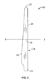
- FIG. 2 is a schematic view of an exemplary configuration of rotor blade 18.
- Rotor blade 18 includes a first end or root section 20 configured to facilitate mounting rotor blade 18 to hub 16 and a second or tip end 22 opposing root section 20.
- a body 24 of rotor blade 18 extends between root section 20 and tip end 22.
- rotor blade 18 includes a first blade section 26, such as a suction side blade section, and an opposing second blade section 28, such as a pressure side blade section, coupled to first blade section 26 to form rotor blade 18.
- a suction side sparcap is provided at an inner surface of the suction side rotor blade shell and/or a pressure side sparcap is provided at an inner surface of the pressure side rotor blade shell.
- the suction side sparcap and/or the pressure side sparcap extend almost the full longitudinal length of rotor blade 18. However, shorter sparcaps are also used in alternative embodiments.
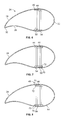
- Figures 3-10 are cross-sectional views of an exemplary body 24 of rotor blade 18 along sectional line 3-3 in Figure 2 .
- first blade section 26 such as a suction side blade section
- second blade section 28 such as a pressure side blade section
- any suitable method may be used to couple second blade section 28 to first blade section 26 to form rotor blade 18.
- first blade section 26 and second blade section 28 are coupled at a leading edge 30 and an opposing trailing edge 32 of rotor blade 18.
- first sparcap 40 is positioned on and coupled to an inner surface 42 of first blade section 26.
- first sparcap 40 includes a carbon material, such as a suitable carbon fiber reinforced matrix, and/or a glass material, such as a suitable glass fiber reinforced matrix.
- Suitable carbon materials include, without limitation, unidirectional or bidirectional carbon roving, unidirectional or bidirectional carbon prepreg, unidirectional or bidirectional carbon tape or mat and any other suitable carbon fiber preforms.
- Carbon prepregs include unidirectional or bidirectional carbon fibers pre-impregnated with a B-stage resin (i.e., carbon fibers enriched with resin prior to lay-up) and carbon fiber preforms are formed by injecting a resin into a dry stack of carbon fibers oriented in a desired orientation, and shaped or formed to a final shape in an external mold or mandrel.
- Suitable glass materials include, without limitation, unidirectional or bidirectional glass roving, unidirectional or bidirectional glass prepreg, unidirectional or bidirectional glass tape or mat and any other suitable glass fiber preforms.
- Glass prepregs include unidirectional or bidirectional glass fibers pre-impregnated with a B-stage resin (i.e., glass fibers enriched with resin prior to lay-up) and glass fiber preforms are formed by injecting a resin into a dry stack of glass fibers oriented in a desired orientation, and shaped or formed to a final shape in an external mold or mandrel.
- a B-stage resin i.e., glass fibers enriched with resin prior to lay-up
- glass fiber preforms are formed by injecting a resin into a dry stack of glass fibers oriented in a desired orientation, and shaped or formed to a final shape in an external mold or mandrel.
- the sparcaps described herein are laminated to an inner surface of the respective blade section.
- a second sparcap 44 including a glass material, such as a suitable glass fiber reinforced matrix, and/or a carbon material, such as a suitable carbon fiber reinforced matrix is positioned on and coupled to inner surface 42 of first blade section 26.
- Second sparcap 44 is positioned with respect to first sparcap 40 in a leading edge direction, i.e., towards leading edge 30, or a trailing edge direction, i.e., towards trailing edge 32, along a cross-sectional width of rotor blade 18.
- first sparcap 40 has a first thickness 46 and second sparcap 44 has a second thickness 48 different from first thickness 46.
- first thickness 46 and/or second thickness 48 varies along a length of rotor blade 18 in certain embodiments.
- First thickness 46 may be different than second thickness 48 at any distance from an end point, such as tip end 22, along a length of rotor blade 18, such as at a distance 49, shown in Figure 2 , from tip end 22.
- First thickness 46 and/or second thickness 48 vary according to design requirements and the configuration selected. However, in one embodiment, first thickness 46 is about 20 mm to about 25 mm and second thickness is about 30 mm to about 35 mm at distance 49.
- Rotor blade 18 also includes a third sparcap 50 positioned on an inner surface 52 of second blade section 28.
- third sparcap 50 includes a carbon material, such as a suitable carbon fiber reinforced matrix, and/or a glass material, such as a suitable glass fiber reinforced matrix.
- Fourth sparcap 54 is positioned with respect to third sparcap 50 in a leading edge direction, i.e., towards leading edge 30, or a trailing edge direction, i.e., towards trailing edge 32, along a cross-sectional width of rotor blade 18.
- a first sparweb 60 couples first sparcap 40 to third sparcap 50 and a second sparweb 62 couples second sparcap 44 to fourth sparcap 54, as shown for example in Figure 3 .
- third sparcap 50 has a third thickness 56 and fourth sparcap 54 has a fourth thickness 58 different from third thickness 56.
- third thickness 56 and/or fourth thickness 58 varies along a length of rotor blade 18 in certain embodiments.
- Third thickness 56 may be different than fourth thickness 58 at any distance from an end point, such as tip end 22, along a length of rotor blade 18, such as at a distance 49, shown in Figure 2 , from tip end 22.
- first sparcap 40 is formed of a carbon material and second sparcap 44 is formed of a glass material. Second sparcap 44 is positioned with respect to first sparcap 40 in the trailing edge direction and coupled to inner surface 42. Further, third sparcap 50 is formed of a carbon material and fourth sparcap 54 is formed of a glass material. Fourth sparcap 54 is positioned with respect to third sparcap 50 in the trailing edge direction and coupled to inner surface 52. First sparcap 40 is coupled to third sparcap 50 by sparweb 60 and second sparcap 44 is coupled to fourth sparcap 54 by sparweb 62.
- first sparcap 40 is formed of a carbon material and second sparcap 44 is formed of a glass material and positioned with respect to first sparcap 40 in the leading edge direction and coupled to inner surface 42, as shown in Figure 4 .
- third sparcap 50 is formed of a carbon material and fourth sparcap 54 is formed of a glass material. Fourth sparcap 54 is positioned with respect to third sparcap 50 in the leading edge direction and coupled to inner surface 52.
- first sparcap 40 is formed of a carbon material and second sparcap 44 is formed of a glass material. As shown in Figure 5 , second sparcap 44 is positioned with respect to first sparcap 40 in the trailing edge direction and coupled to inner surface 42.
- third sparcap 50 is formed of a glass material and fourth sparcap 54 is formed of a carbon material. Fourth sparcap 54 is positioned with respect to third sparcap 50 in the trailing edge direction and coupled to inner surface 52.
- First sparcap 40 is coupled to third sparcap 50 by sparweb 60 and second sparcap 44 is coupled to fourth sparcap 54 by sparweb 62.
- first sparcap 40 is formed of a carbon material and second sparcap 44 is formed of a glass material and positioned with respect to first sparcap 40 in the leading edge direction and coupled to inner surface 42, as shown in Figure 6 .
- third sparcap 50 is formed of a glass material and fourth sparcap 54 is formed of a carbon material. Fourth sparcap 54 is positioned with respect to third sparcap 50 in the leading edge direction and coupled to inner surface 52.
- first sparcap 40 and/or third sparcap 50 include a glass material in addition to a carbon material.
- first sparcap 40 is positioned on and coupled to inner surface 42 of first blade section 26.
- first sparcap 40 includes a carbon material layer 70, such as a suitable carbon fiber reinforced matrix layer, that is coupled directly to inner surface 42 and a glass material layer 72, such as a suitable glass fiber reinforced matrix layer, coupled to carbon material layer 70.
- Second sparcap 44 includes a glass material and is positioned on and coupled to inner surface 42 of first blade section 26. As shown in Figure 7 , second sparcap 44 is positioned with respect to first sparcap 40 in the trailing edge direction, i.e., towards trailing edge 32.
- second sparcap 44 is positioned with respect to first sparcap 40 in the leading edge direction, i.e., towards leading edge 30.
- second sparcap 44 and/or fourth sparcap 54 includes a carbon material (not shown), such as a carbon material layer, in addition to a glass material, such as a glass material layer.
- a rotor blade including alternative sparcap systems including a single glass sparcap (Sample 1), a glass sparcap positioned in a leading edge direction with respect to a carbon sparcap along a cross-sectional width of the rotor blade (Sample 2), a carbon sparcap positioned in a leading edge direction with respect to a glass sparcap along a cross-sectional width of the rotor blade (Sample 3), and a single carbon sparcap (Sample 4) were tested to optimize various parameters.
- Each rotor blade was tested for a sparcap mass, a tip deflection and a blade static moment, as defined above.
- a rotor blade with a two sparcap system including sparcaps made of different materials i.e., a first sparcap made of a suitable carbon material and a second sparcap positioned adjacent first sparcap and made of a suitable glass material, such as Sample 2 and Sample 3, substantially decreased a weight of the rotor blade when compared to a rotor blade including only a glass sparcap (Sample 1) without undesirably decreasing a tip deflection and/or increasing a blade static moment for the rotor blade during operation.
- the two sparcap system allows wind turbine rotor blade designers to make suitable design choices based on design requirements.
- Two sparcap system using different materials effectively utilizes properties of the two different materials to satisfy the stiffness requirements for wind turbine rotor blades.
- the addition of a carbon sparcap contributes to a greater stiffness, thus, reducing an amount of glass material required to meet the stiffness requirements for wind turbine rotor blades.
- dimensions of both sparcaps can be optimized in view of design requirements.
- the sparcap system and the resulting wind turbine rotor blades meet stiffness requirements for a longer rotor blade at a low cost, meet static moment specifications for the rotor blade, enable rotor blade designers to perform a tradeoff study between cost and mass of the rotor blade, and facilitate suppressing buckling issues associated with a longer rotor blade.
Landscapes
- Engineering & Computer Science (AREA)
- Life Sciences & Earth Sciences (AREA)
- Sustainable Development (AREA)
- Sustainable Energy (AREA)
- Chemical & Material Sciences (AREA)
- Combustion & Propulsion (AREA)
- Mechanical Engineering (AREA)
- General Engineering & Computer Science (AREA)
- Wind Motors (AREA)
Abstract
A rotor blade (18) for a wind turbine (10) is provided. The rotor blade (18) includes a first blade section (26) and a second blade section (28) coupled to the first blade section to form the rotor blade, each of the first blade section and the second blade section having a leading edge (30) and a trailing edge (32), a first sparcap (40) including a carbon material (70) and positioned on an inner surface (42) of the first blade section, and a second sparcap (44) including a glass material (72) and positioned on the first blade section, the second sparcap positioned with respect to the first sparcap in one of a leading edge direction and a trailing edge direction.
Description
- The embodiments described herein relate generally to a wind turbine rotor blade and, more particularly, to a sparcap system for a wind turbine rotor blade.
- Wind turbine blades typically include two blade shell portions of fiber reinforced polymer. The blade shell portions are molded and then coupled together along cooperating edges using a suitable adhesive material. At least some turbine blades include one or more bracings that are adhesively coupled to an inner surface of a first blade shell portion. A cooperating second blade shell portion is then arranged on top of the bracings and adhesively coupled to the first blade shell portion along its edges.
- The blade shell portions are typically made using suitable evenly distributed fibers, fiber bundles, or mats of fibers layered in a mold part. However, the blade shell portions are relatively light and have only low rigidity. Therefore, a stiffness and a rigidity, as well as a buckling strength, of the blade shell portions may not withstand the loads and forces exerted on the rotor blade during operation. To increase the strength of the rotor blades, the blade shell portions are reinforced by sparcaps laminated to the inner surface of the blade shell portions. Typically, the sparcaps extend substantially along a longitudinal length of the rotor blade.
- Flapwise loads, which cause the rotor blade tip to deflect towards the wind turbine tower, are transferred along the rotor blade predominantly through the sparcaps. At least some conventional rotor blades include sparcaps fabricated from a suitable glass material or a suitable carbon material. The stiffness requirements of the conventional wind turbine rotor blade designs are met by a completely glass sparcap or a completely carbon sparcap, thus tolerating a mass or cost penalty. Due to different stiffness-to-strength ratios for these materials, usage of these materials separately results in either an over-stiffened rotor blade or an over-strengthened rotor blade.
- Further, with a continuously increasing length of wind turbine rotor blades in recent years, meeting stiffness requirements is a major concern in the structural design of the rotor blade. Stiffness requirements met by glass sparcaps makes the rotor blade heavy and over-strengthened, while carbon sparcaps yield a light, but over-stiffened rotor blade. Carbon sparcaps are advantageous due to high stiffness and low density but, on the other hand, carbon sparcaps are expensive compared to glass sparcaps. As such, conventional blade designs are either over-strengthened resulting in a heavier design or over-stiffened resulting in costly design.
- In one aspect according to the present invention, a rotor blade for a wind turbine is provided. The rotor blade includes a first blade section and a second blade section coupled to the first blade section to form the rotor blade. Each of the first blade section and the second blade section has a leading edge and a trailing edge. A first sparcap including a carbon material is positioned on and coupled to an inner surface of the first blade section. A second sparcap including a glass material is positioned on the first blade section. The second sparcap is positioned with respect to the first sparcap in one of a leading edge direction and a trailing edge direction and coupled to the inner surface of the first blade section.
- In another aspect, a rotor blade for a wind turbine is provided. The rotor blade includes a first blade section and a second blade section coupled to the first blade section to form the rotor blade. Each of the first blade section and the second blade section has a leading edge and a trailing edge. A first sparcap including a glass material is positioned on and coupled to an inner surface of the first blade section. A second sparcap is coupled to the first sparcap. The second sparcap includes a glass material and is positioned on and coupled to an inner surface of the second blade section. A third sparcap including a carbon material is positioned on and coupled to the inner surface of the first blade section. The third sparcap is positioned with respect to the first sparcap in one of a leading edge direction and a trailing edge direction. A fourth sparcap is coupled to the third sparcap. The fourth sparcap includes a carbon material and is positioned on and coupled to the inner surface of the second blade section.
- In yet another aspect, a method is provided for fabricating a rotor blade for a wind turbine. The method includes providing a first blade section and a second blade section. Each of the first blade section and the second blade section has a leading edge and a trailing edge. A first sparcap including a carbon material is coupled to an inner surface of the first blade section. A second sparcap including a glass material is positioned with respect to the first sparcap in one of a leading edge direction and a trailing edge direction. The second sparcap is coupled to the inner surface of the first blade section.
- Various aspects and embodiments of the present invention will now be described in connection with the accompanying drawings; in which:
-
Figure 1 is a schematic view of a wind turbine; -
Figure 2 is a side view of an exemplary wind turbine rotor blade; and -
Figures 3-10 are cross-sectional views of exemplary wind turbine rotor blades. - The embodiments described herein provide a rotor blade for a wind turbine that includes a sparcap system suitable for providing sufficient strength to the rotor blade while decreasing an overall weight of the rotor blade and/or fabrication cost. The sparcap system includes a first sparcap including a carbon material positioned on and coupled to an inner surface of a first blade section of the rotor blade and a second sparcap including a glass material positioned adjacent the first sparcap and coupled to the first blade section, and with respect to the first sparcap in a leading edge direction or a trailing edge direction along a cross-sectional width of the rotor blade. The use of a first sparcap including a carbon material and a second sparcap adjacent the first sparcap including a glass material allows for fabrication of a longer and/or a larger rotor blade, while reducing sparcap mass and blade static moment, which can be defined as a rotor blade dead weight moment on a wind turbine rotor hub.
-
Figure 1 is a schematic view of awind turbine 10.Wind turbine 10 includes atower 12 to which amachine nacelle 14 is mounted at a first or top end portion. Ahub 16 having a plurality ofrotor blades 18, such as threerotor blades 18, is mounted to a first lateral end ofmachine nacelle 14. -
Figure 2 is a schematic view of an exemplary configuration ofrotor blade 18.Rotor blade 18 includes a first end orroot section 20 configured to facilitatemounting rotor blade 18 tohub 16 and a second ortip end 22opposing root section 20. Abody 24 ofrotor blade 18 extends betweenroot section 20 andtip end 22. In one embodiment,rotor blade 18 includes afirst blade section 26, such as a suction side blade section, and an opposingsecond blade section 28, such as a pressure side blade section, coupled tofirst blade section 26 to formrotor blade 18. Further, a suction side sparcap is provided at an inner surface of the suction side rotor blade shell and/or a pressure side sparcap is provided at an inner surface of the pressure side rotor blade shell. Typically, the suction side sparcap and/or the pressure side sparcap extend almost the full longitudinal length ofrotor blade 18. However, shorter sparcaps are also used in alternative embodiments. -
Figures 3-10 are cross-sectional views of anexemplary body 24 ofrotor blade 18 along sectional line 3-3 inFigure 2 . As shown inFigures 3-10 ,first blade section 26, such as a suction side blade section, is coupled tosecond blade section 28, such as a pressure side blade section, to formrotor blade 18 defining a contour ofrotor blade 18 as shown in the cross-sectional views. It should be apparent to those skilled in the art and guided by the teachings herein provided that any suitable method may be used to couplesecond blade section 28 tofirst blade section 26 to formrotor blade 18. In this embodiment,first blade section 26 andsecond blade section 28 are coupled at a leadingedge 30 and an opposingtrailing edge 32 ofrotor blade 18. - Referring further to
Figures 3-10 , afirst sparcap 40 is positioned on and coupled to aninner surface 42 offirst blade section 26. In the embodiments shown inFigures 3-10 ,first sparcap 40 includes a carbon material, such as a suitable carbon fiber reinforced matrix, and/or a glass material, such as a suitable glass fiber reinforced matrix. Suitable carbon materials include, without limitation, unidirectional or bidirectional carbon roving, unidirectional or bidirectional carbon prepreg, unidirectional or bidirectional carbon tape or mat and any other suitable carbon fiber preforms. Carbon prepregs include unidirectional or bidirectional carbon fibers pre-impregnated with a B-stage resin (i.e., carbon fibers enriched with resin prior to lay-up) and carbon fiber preforms are formed by injecting a resin into a dry stack of carbon fibers oriented in a desired orientation, and shaped or formed to a final shape in an external mold or mandrel. Suitable glass materials include, without limitation, unidirectional or bidirectional glass roving, unidirectional or bidirectional glass prepreg, unidirectional or bidirectional glass tape or mat and any other suitable glass fiber preforms. Glass prepregs include unidirectional or bidirectional glass fibers pre-impregnated with a B-stage resin (i.e., glass fibers enriched with resin prior to lay-up) and glass fiber preforms are formed by injecting a resin into a dry stack of glass fibers oriented in a desired orientation, and shaped or formed to a final shape in an external mold or mandrel. - In one embodiment, the sparcaps described herein are laminated to an inner surface of the respective blade section. However, it should be apparent to those skilled in the art and guided by the teachings herein provided that any suitable method may be used to couple the sparcaps to the inner surface of the respective blade section. A
second sparcap 44 including a glass material, such as a suitable glass fiber reinforced matrix, and/or a carbon material, such as a suitable carbon fiber reinforced matrix, is positioned on and coupled toinner surface 42 offirst blade section 26.Second sparcap 44 is positioned with respect tofirst sparcap 40 in a leading edge direction, i.e., towards leadingedge 30, or a trailing edge direction, i.e., towards trailingedge 32, along a cross-sectional width ofrotor blade 18. - In one embodiment,
first sparcap 40 has a first thickness 46 andsecond sparcap 44 has a second thickness 48 different from first thickness 46. In a particular embodiment, first thickness 46 and/or second thickness 48 varies along a length ofrotor blade 18 in certain embodiments. First thickness 46 may be different than second thickness 48 at any distance from an end point, such astip end 22, along a length ofrotor blade 18, such as at adistance 49, shown inFigure 2 , fromtip end 22. First thickness 46 and/or second thickness 48 vary according to design requirements and the configuration selected. However, in one embodiment, first thickness 46 is about 20 mm to about 25 mm and second thickness is about 30 mm to about 35 mm atdistance 49. -
Rotor blade 18 also includes athird sparcap 50 positioned on aninner surface 52 ofsecond blade section 28. In the embodiments shown inFigures 3-10 ,third sparcap 50 includes a carbon material, such as a suitable carbon fiber reinforced matrix, and/or a glass material, such as a suitable glass fiber reinforced matrix. Afourth sparcap 54 including a glass material, such as a suitable glass fiber reinforced matrix, and/or a carbon material, such as a suitable carbon fiber reinforced matrix, is positioned on and coupled toinner surface 52 ofsecond blade section 28.Fourth sparcap 54 is positioned with respect tothird sparcap 50 in a leading edge direction, i.e., towards leadingedge 30, or a trailing edge direction, i.e., towards trailingedge 32, along a cross-sectional width ofrotor blade 18. Afirst sparweb 60 couples first sparcap 40 tothird sparcap 50 and asecond sparweb 62 couples second sparcap 44 tofourth sparcap 54, as shown for example inFigure 3 . - In one embodiment,
third sparcap 50 has a third thickness 56 andfourth sparcap 54 has a fourth thickness 58 different from third thickness 56. In a particular embodiment, third thickness 56 and/or fourth thickness 58 varies along a length ofrotor blade 18 in certain embodiments. Third thickness 56 may be different than fourth thickness 58 at any distance from an end point, such astip end 22, along a length ofrotor blade 18, such as at adistance 49, shown inFigure 2 , fromtip end 22. - Referring further to
Figure 3 , in one embodiment,first sparcap 40 is formed of a carbon material andsecond sparcap 44 is formed of a glass material.Second sparcap 44 is positioned with respect tofirst sparcap 40 in the trailing edge direction and coupled toinner surface 42. Further,third sparcap 50 is formed of a carbon material andfourth sparcap 54 is formed of a glass material.Fourth sparcap 54 is positioned with respect tothird sparcap 50 in the trailing edge direction and coupled toinner surface 52.First sparcap 40 is coupled tothird sparcap 50 bysparweb 60 andsecond sparcap 44 is coupled tofourth sparcap 54 bysparweb 62. Alternatively,first sparcap 40 is formed of a carbon material andsecond sparcap 44 is formed of a glass material and positioned with respect tofirst sparcap 40 in the leading edge direction and coupled toinner surface 42, as shown inFigure 4 . Further,third sparcap 50 is formed of a carbon material andfourth sparcap 54 is formed of a glass material.Fourth sparcap 54 is positioned with respect tothird sparcap 50 in the leading edge direction and coupled toinner surface 52. - Referring to
Figures 5 and6 , in alternative embodiments,first sparcap 40 is formed of a carbon material andsecond sparcap 44 is formed of a glass material. As shown inFigure 5 ,second sparcap 44 is positioned with respect tofirst sparcap 40 in the trailing edge direction and coupled toinner surface 42. However, in this alternative embodiment,third sparcap 50 is formed of a glass material andfourth sparcap 54 is formed of a carbon material.Fourth sparcap 54 is positioned with respect tothird sparcap 50 in the trailing edge direction and coupled toinner surface 52.First sparcap 40 is coupled tothird sparcap 50 bysparweb 60 andsecond sparcap 44 is coupled tofourth sparcap 54 bysparweb 62. Alternatively,first sparcap 40 is formed of a carbon material andsecond sparcap 44 is formed of a glass material and positioned with respect tofirst sparcap 40 in the leading edge direction and coupled toinner surface 42, as shown inFigure 6 . Further,third sparcap 50 is formed of a glass material andfourth sparcap 54 is formed of a carbon material.Fourth sparcap 54 is positioned with respect tothird sparcap 50 in the leading edge direction and coupled toinner surface 52. - As shown in
Figures 7-10 ,first sparcap 40 and/orthird sparcap 50 include a glass material in addition to a carbon material. Referring further toFigures 7 and 8 ,first sparcap 40 is positioned on and coupled toinner surface 42 offirst blade section 26. In one embodiment,first sparcap 40 includes acarbon material layer 70, such as a suitable carbon fiber reinforced matrix layer, that is coupled directly toinner surface 42 and aglass material layer 72, such as a suitable glass fiber reinforced matrix layer, coupled tocarbon material layer 70.Second sparcap 44 includes a glass material and is positioned on and coupled toinner surface 42 offirst blade section 26. As shown inFigure 7 ,second sparcap 44 is positioned with respect tofirst sparcap 40 in the trailing edge direction, i.e., towards trailingedge 32. Alternatively, as shown inFigure 8 ,second sparcap 44 is positioned with respect tofirst sparcap 40 in the leading edge direction, i.e., towards leadingedge 30. In a further alternative embodiment,second sparcap 44 and/orfourth sparcap 54 includes a carbon material (not shown), such as a carbon material layer, in addition to a glass material, such as a glass material layer. - As shown in Table 1, a rotor blade including alternative sparcap systems including a single glass sparcap (Sample 1), a glass sparcap positioned in a leading edge direction with respect to a carbon sparcap along a cross-sectional width of the rotor blade (Sample 2), a carbon sparcap positioned in a leading edge direction with respect to a glass sparcap along a cross-sectional width of the rotor blade (Sample 3), and a single carbon sparcap (Sample 4) were tested to optimize various parameters. Each rotor blade was tested for a sparcap mass, a tip deflection and a blade static moment, as defined above.
Table 1 Parameter Sample 1 Sample 2 Sample 3Sample 4 Sparcap Mass (kg) 4,809 2,904 2,821 1,485 Tip Deflection (mm) 5,800 5,800 5,800 5,267 Moment (kg-m) 221,768 174,834 179,026 144,734 - As shown in Table 1, providing a rotor blade with a two sparcap system including sparcaps made of different materials, i.e., a first sparcap made of a suitable carbon material and a second sparcap positioned adjacent first sparcap and made of a suitable glass material, such as Sample 2 and
Sample 3, substantially decreased a weight of the rotor blade when compared to a rotor blade including only a glass sparcap (Sample 1) without undesirably decreasing a tip deflection and/or increasing a blade static moment for the rotor blade during operation. The two sparcap system allows wind turbine rotor blade designers to make suitable design choices based on design requirements. - Two sparcap system using different materials effectively utilizes properties of the two different materials to satisfy the stiffness requirements for wind turbine rotor blades. The addition of a carbon sparcap contributes to a greater stiffness, thus, reducing an amount of glass material required to meet the stiffness requirements for wind turbine rotor blades. As a result, dimensions of both sparcaps can be optimized in view of design requirements.
- The sparcap system and the resulting wind turbine rotor blades meet stiffness requirements for a longer rotor blade at a low cost, meet static moment specifications for the rotor blade, enable rotor blade designers to perform a tradeoff study between cost and mass of the rotor blade, and facilitate suppressing buckling issues associated with a longer rotor blade.
- This written description uses examples to disclose the invention, including the preferred mode, and also to enable any person skilled in the art to practice the invention, including making and using any devices or systems and performing any incorporated methods. The patentable scope of the invention is defined by the claims, and may include other examples that occur to those skilled in the art. Such other examples are intended to be within the scope of the claims if they have structural elements that do not differ from the literal language of the claims, or if they include equivalent structural elements with insubstantial differences from the literal language of the claims.
- Various aspects and embodiments of the present invention are defined by the following numbered clauses:
- 1. A rotor blade for a wind turbine, said rotor blade comprising:
- a first blade section and a second blade section coupled to said first blade section to form said rotor blade, each of said first blade section and said second blade section having a leading edge and a trailing edge;
- a first sparcap comprising a carbon material and positioned on an inner surface of said first blade section; and
- a second sparcap comprising a glass material and positioned on said first blade section, said second sparcap positioned with respect to said first sparcap in one of a leading edge direction and a trailing edge direction.
- 2. A rotor blade in accordance with Clause 1 further comprising:
- a third sparcap comprising a carbon material and positioned on an inner surface of said second blade section; and
- a fourth sparcap comprising a glass material and positioned on said second blade section, said fourth sparcap positioned with respect to said third sparcap in one of the leading edge direction and the trailing edge direction.
- 3. A rotor blade in accordance with any preceding Clause further comprising:
- a first sparweb coupling said first sparcap to said third sparcap; and
- a second sparweb coupling said second sparcap to said fourth sparcap.
- 4. A rotor blade in accordance with any preceding Clause further comprising:
- a first sparweb coupling said first sparcap to said fourth sparcap; and
- a second sparweb coupling said second sparcap to said third sparcap.
- 5. A rotor blade in accordance with any preceding Clause wherein said first sparcap comprises a carbon fiber reinforced matrix.
- 6. A rotor blade in accordance with any preceding Clause wherein said second sparcap comprises a glass fiber reinforced matrix.
- 7. A rotor blade in accordance with any preceding Clause wherein said first sparcap has a first thickness and said second sparcap has a second thickness.
- 8. A rotor blade in accordance with any preceding Clause wherein at least one of said first thickness and said second thickness varies along a length of said rotor blade.
- 9. A rotor blade in accordance with any preceding Clause wherein said first thickness is different than said second thickness at a first distance from an end point of said rotor blade along a length of said rotor blade.
- 10. A rotor blade in accordance with any preceding Clause wherein said first sparcap further comprises a glass material.
- 11. A rotor blade in accordance with any preceding Clause wherein said second sparcap further comprises a carbon material.
- 12. A rotor blade for a wind turbine, said rotor blade comprising:
- a first blade section and a second blade section coupled to said first blade section to form said rotor blade, each of said first blade section and said second blade section having a leading edge and a trailing edge;
- a first sparcap comprising a glass material, said first sparcap positioned on an inner surface of said first blade section;
- a second sparcap coupled to said first sparcap, said second sparcap comprising a glass material and positioned on an inner surface of said second blade section;
- a third sparcap comprising a carbon material and positioned on the inner surface of said first blade section, said third sparcap positioned with respect to said first sparcap in one of a leading edge direction and a trailing edge direction; and
- a fourth sparcap coupled to said third sparcap, said fourth sparcap comprising a carbon material and positioned on the inner surface of said second blade section.
- 13. A rotor blade in accordance with any preceding Clause wherein at least one of said third sparcap and said fourth sparcap further comprises a glass material.
- 14. A rotor blade in accordance with any preceding Clause further comprising:
- a first sparweb coupling said first sparcap to said second sparcap; and
- a second sparweb coupling said third sparcap to said fourth sparcap.
- 15. A rotor blade in accordance with any preceding Clause wherein at least one of said first sparcap and said second sparcap comprises a glass fiber reinforced matrix.
- 16. A rotor blade in accordance with any preceding Clause wherein at least one of said third sparcap and said fourth sparcap comprises a carbon fiber reinforced matrix.
- 17. A rotor blade in accordance with any preceding Clause wherein said first sparcap has a first thickness and said third sparcap has a second thickness, at least one of said first thickness and said second thickness varies along a length of said rotor blade.
- 18. A method for fabricating a rotor blade for a wind turbine, said method comprising:
- providing a first blade section and a second blade section, each of said first blade section and said second blade section having a leading edge and a trailing edge;
- coupling a first sparcap comprising a carbon material to an inner surface of the first blade section;
- positioning a second sparcap comprising a glass material with respect to the first sparcap in one of a leading edge direction and a trailing edge direction; and
- coupling the second sparcap to the inner surface of the first blade section.
- 19. A method in accordance with
Clause 18 further comprising:- coupling a third sparcap comprising a carbon material to an inner surface of the second blade section;
- positioning a fourth sparcap comprising a glass material with respect to the third sparcap in one of the leading edge direction and the trailing edge direction; and
- coupling the fourth sparcap to the inner surface of the second blade section.
- 20. A method in accordance with
Clause 18 or 19 further comprising coupling the first sparcap to the third sparcap and coupling the second sparcap to the fourth sparcap.
Claims (10)
- A rotor blade (18) for a wind turbine (10), said rotor blade comprising:a first blade section (26) and a second blade section (28) coupled to said first blade section to form said rotor blade, each of said first blade section and said second blade section having a leading edge (30) and a trailing edge (32);a first sparcap (40) comprising a carbon material (70) and positioned on an inner surface (42) of said first blade section; anda second sparcap (44) comprising a glass material (72) and positioned on said first blade section, said second sparcap positioned with respect to said first sparcap in one of a leading edge direction and a trailing edge direction.
- A rotor blade (18) in accordance with Claim 1 further comprising:a third sparcap (50) comprising a carbon material (70) and positioned on an inner surface (42) of said second blade section (28); anda fourth sparcap (54) comprising a glass material and positioned on said second blade section, said fourth sparcap positioned with respect to said third sparcap in one of the leading edge direction and the trailing edge direction.
- A rotor blade (18) in accordance with Claim 2 further comprising:a first sparweb (60) coupling said first sparcap (40) to said third sparcap (50); anda second sparweb (62) coupling said second sparcap (44) to said fourth sparcap (54).
- A rotor blade (18) in accordance with Claim 2 or Claim 3 further comprising:a first sparweb (60) coupling said first sparcap (40) to said fourth sparcap (54); anda second sparweb (62) coupling said second sparcap (44) to said third sparcap (50).
- A rotor blade (18) in accordance with any preceding Claim wherein said first sparcap (40) comprises a carbon fiber reinforced matrix.
- A rotor blade (18) in accordance with any preceding Claim wherein said second sparcap (44) comprises a glass fiber reinforced matrix.
- A rotor blade (18) in accordance with any preceding Claim wherein said first sparcap (40) has a first thickness (46) and said second sparcap (44) has a second thickness (48).
- A rotor blade (18) in accordance with Claim 7 wherein at least one of said first thickness (46) and said second thickness (48) varies along a length of said rotor blade.
- A rotor blade (18) in accordance with Claim 7 or 8 wherein said first thickness (46) is different than said second thickness (48) at a first distance from an end point of said rotor blade along a length of said rotor blade.
- A rotor blade (18) in accordance with any preceding Claim wherein said first sparcap (40) further comprises a glass material.
Applications Claiming Priority (1)
| Application Number | Priority Date | Filing Date | Title |
|---|---|---|---|
| US12/332,729 US20100143142A1 (en) | 2008-12-11 | 2008-12-11 | Sparcap system for wind turbine rotor blade and method of fabricating wind turbine rotor blade |
Publications (1)
| Publication Number | Publication Date |
|---|---|
| EP2239461A2 true EP2239461A2 (en) | 2010-10-13 |
Family
ID=42184115
Family Applications (1)
| Application Number | Title | Priority Date | Filing Date |
|---|---|---|---|
| EP09177436A Withdrawn EP2239461A2 (en) | 2008-12-11 | 2009-11-30 | Sparcap system for wind turbine rotor blade and method of fabricating wind turbine rotor blade |
Country Status (3)
| Country | Link |
|---|---|
| US (1) | US20100143142A1 (en) |
| EP (1) | EP2239461A2 (en) |
| CN (1) | CN101749173A (en) |
Cited By (3)
| Publication number | Priority date | Publication date | Assignee | Title |
|---|---|---|---|---|
| DE102018009338A1 (en) * | 2018-11-28 | 2020-05-28 | Senvion Gmbh | Rotor blade component, process for its manufacture and wind turbine |
| EP4086453A1 (en) * | 2021-05-04 | 2022-11-09 | Doosan Enerbility Co., Ltd. | Wind turbine blade and wind turbine including the same |
| EP4086452A1 (en) * | 2021-05-04 | 2022-11-09 | Doosan Enerbility Co., Ltd. | Method of manufacturing wind turbine blade |
Families Citing this family (14)
| Publication number | Priority date | Publication date | Assignee | Title |
|---|---|---|---|---|
| US7841835B2 (en) * | 2009-02-20 | 2010-11-30 | General Electric Company | Spar cap for wind turbine blades |
| US8075278B2 (en) * | 2009-05-21 | 2011-12-13 | Zuteck Michael D | Shell structure of wind turbine blade having regions of low shear modulus |
| US8079819B2 (en) * | 2009-05-21 | 2011-12-20 | Zuteck Michael D | Optimization of premium fiber material usage in wind turbine spars |
| US8702397B2 (en) * | 2009-12-01 | 2014-04-22 | General Electric Company | Systems and methods of assembling a rotor blade for use in a wind turbine |
| DE102010002432A1 (en) * | 2010-02-26 | 2011-09-01 | Repower Systems Ag | Rotor blade for a wind turbine, wind turbine and method for producing a rotor blade |
| US20110142662A1 (en) * | 2010-10-28 | 2011-06-16 | General Electric Company | Spar Cap Assembly for a Wind Turbine Rotor Blade |
| GB2497578B (en) | 2011-12-16 | 2015-01-14 | Vestas Wind Sys As | Wind turbine blades |
| CN103994031B (en) * | 2014-05-21 | 2016-06-01 | 航天材料及工艺研究所 | A kind of carbon fibre fabric strengthens polymer matrix composites main beam cap and manufacture method thereof |
| US9951750B2 (en) * | 2015-07-30 | 2018-04-24 | General Electric Company | Rotor blade with interior shelf for a flat plate spar cap |
| EP3380721B1 (en) | 2015-11-26 | 2020-01-08 | Vestas Wind Systems A/S | Improvements relating to the manufacture of wind turbine blades |
| DK3712424T3 (en) * | 2019-03-21 | 2023-10-09 | Siemens Gamesa Renewable Energy As | WINDMILL BLADE AND WINDMILL |
| EP3904670A1 (en) * | 2020-04-27 | 2021-11-03 | Siemens Gamesa Renewable Energy A/S | Wind turbine blade |
| CN114347576B (en) * | 2021-12-29 | 2023-06-27 | 江苏金风科技有限公司 | Main beam of blade and blade |
| EP4390111A1 (en) * | 2022-12-22 | 2024-06-26 | Vestas Wind Systems A/S | A wind turbine blade |
Family Cites Families (13)
| Publication number | Priority date | Publication date | Assignee | Title |
|---|---|---|---|---|
| US4081220A (en) * | 1976-12-17 | 1978-03-28 | United Technologies Corporation | Semi-spar wound blade |
| US4264278A (en) * | 1977-10-31 | 1981-04-28 | Oscar Weingart | Blade or spar |
| AT398064B (en) * | 1992-07-01 | 1994-09-26 | Hoac Austria Flugzeugwerk Wr N | PLASTIC COMPOSITE PROFILE, ESPECIALLY WING SLEEVE FOR AIRCRAFT CONSTRUCTION |
| EP0783431B1 (en) * | 1994-08-31 | 2000-01-19 | United Technologies Corporation | Fiber reinforced composite spar for a rotary wing aircraft and method of manufacture thereof |
| DE69839091T2 (en) * | 1998-12-16 | 2009-01-29 | Lantor B.V. | Core material for closed molding systems |
| JP3891092B2 (en) * | 2001-10-23 | 2007-03-07 | ヤマハ株式会社 | Steering wheel |
| DK175275B1 (en) * | 2002-03-19 | 2004-08-02 | Lm Glasfiber As | Transition area in wind turbine blade |
| US20050186081A1 (en) * | 2004-02-24 | 2005-08-25 | Mohamed Mansour H. | Wind blade spar cap and method of making |
| US7153090B2 (en) * | 2004-12-17 | 2006-12-26 | General Electric Company | System and method for passive load attenuation in a wind turbine |
| US20070149084A1 (en) * | 2005-12-22 | 2007-06-28 | Magna International Inc. | Natural fiber as core material in composite sandwich structure |
| US7427189B2 (en) * | 2006-02-13 | 2008-09-23 | General Electric Company | Wind turbine rotor blade |
| JP4699255B2 (en) * | 2006-03-24 | 2011-06-08 | 三菱重工業株式会社 | Windmill wing |
| US7976282B2 (en) * | 2007-01-26 | 2011-07-12 | General Electric Company | Preform spar cap for a wind turbine rotor blade |
-
2008
- 2008-12-11 US US12/332,729 patent/US20100143142A1/en not_active Abandoned
-
2009
- 2009-11-30 EP EP09177436A patent/EP2239461A2/en not_active Withdrawn
- 2009-12-11 CN CN200910258599A patent/CN101749173A/en active Pending
Cited By (6)
| Publication number | Priority date | Publication date | Assignee | Title |
|---|---|---|---|---|
| DE102018009338A1 (en) * | 2018-11-28 | 2020-05-28 | Senvion Gmbh | Rotor blade component, process for its manufacture and wind turbine |
| US12031517B2 (en) | 2018-11-28 | 2024-07-09 | Siemens Gamesa Renewable Energy Service Gmbh | Rotor blade component, method of manufacturing a rotor blade component, and a wind energy installation |
| EP4086453A1 (en) * | 2021-05-04 | 2022-11-09 | Doosan Enerbility Co., Ltd. | Wind turbine blade and wind turbine including the same |
| EP4086452A1 (en) * | 2021-05-04 | 2022-11-09 | Doosan Enerbility Co., Ltd. | Method of manufacturing wind turbine blade |
| US11754038B2 (en) | 2021-05-04 | 2023-09-12 | Doosan Enerbility Co., Ltd. | Wind turbine blade and wind turbine including the same |
| US12240190B2 (en) | 2021-05-04 | 2025-03-04 | Doosan Enerbility Co., Ltd. | Method of manufacturing wind turbine blade |
Also Published As
| Publication number | Publication date |
|---|---|
| CN101749173A (en) | 2010-06-23 |
| US20100143142A1 (en) | 2010-06-10 |
Similar Documents
| Publication | Publication Date | Title |
|---|---|---|
| EP2239461A2 (en) | Sparcap system for wind turbine rotor blade and method of fabricating wind turbine rotor blade | |
| EP2204576A2 (en) | Sparcap for wind turbine rotor blade and method of fabricating wind turbine rotor blade | |
| EP2511477B1 (en) | Wind turbine blade with transition region | |
| US8753092B2 (en) | Rotor blade for a wind turbine and methods of manufacturing the same | |
| CN100376790C (en) | Wind turbine blade with carbon fiber tip | |
| CA2884412C (en) | Composite fiber component and rotor blade | |
| DK2363599T3 (en) | A rotor blade for a wind turbine, wind turbine and method of producing a rotor blade | |
| WO2013010979A2 (en) | Wind turbine blade with transition region | |
| EP3394430B1 (en) | Wind turbine blades and related methods of manufacturing | |
| US20110171038A1 (en) | Wind turbine rotor blade and producing method of wind turbine rotor blade | |
| EP2357358A1 (en) | Rotor blade of a wind turbine | |
| US20070095982A1 (en) | Single piece fuselage barrel | |
| US8480371B2 (en) | Wind turbine rotor blade and wind-generating wind turbine | |
| US20110142662A1 (en) | Spar Cap Assembly for a Wind Turbine Rotor Blade | |
| US20110286853A1 (en) | Blade of a wind turbine | |
| WO2016058325A1 (en) | Large-size wind power blade having multi-beam structure and manufacturing method therefor | |
| US20230175476A1 (en) | Wind turbine blade | |
| CN116601384A (en) | Wind turbine blade with buckling-resistant spar caps | |
| US20240295210A1 (en) | A blade for a wind turbine | |
| WO2026052286A1 (en) | Wind turbine rotor blade and a method of manufacturing a wind turbine rotor blade | |
| CN118234940A (en) | Spar caps for wind turbine blades |
Legal Events
| Date | Code | Title | Description |
|---|---|---|---|
| PUAI | Public reference made under article 153(3) epc to a published international application that has entered the european phase |
Free format text: ORIGINAL CODE: 0009012 |
|
| AK | Designated contracting states |
Kind code of ref document: A2 Designated state(s): AT BE BG CH CY CZ DE DK EE ES FI FR GB GR HR HU IE IS IT LI LT LU LV MC MK MT NL NO PL PT RO SE SI SK SM TR |
|
| AX | Request for extension of the european patent |
Extension state: AL BA RS |
|
| STAA | Information on the status of an ep patent application or granted ep patent |
Free format text: STATUS: THE APPLICATION IS DEEMED TO BE WITHDRAWN |
|
| 18D | Application deemed to be withdrawn |
Effective date: 20130601 |
|
| P01 | Opt-out of the competence of the unified patent court (upc) registered |
Effective date: 20230522 |