EP2239418A2 - Feeding Film Cooling Holes from Seal Slots - Google Patents
Feeding Film Cooling Holes from Seal Slots Download PDFInfo
- Publication number
- EP2239418A2 EP2239418A2 EP10158249A EP10158249A EP2239418A2 EP 2239418 A2 EP2239418 A2 EP 2239418A2 EP 10158249 A EP10158249 A EP 10158249A EP 10158249 A EP10158249 A EP 10158249A EP 2239418 A2 EP2239418 A2 EP 2239418A2
- Authority
- EP
- European Patent Office
- Prior art keywords
- cooling
- component
- seal
- slot
- cavity
- Prior art date
- Legal status (The legal status is an assumption and is not a legal conclusion. Google has not performed a legal analysis and makes no representation as to the accuracy of the status listed.)
- Granted
Links
Images
Classifications
-
- F—MECHANICAL ENGINEERING; LIGHTING; HEATING; WEAPONS; BLASTING
- F01—MACHINES OR ENGINES IN GENERAL; ENGINE PLANTS IN GENERAL; STEAM ENGINES
- F01D—NON-POSITIVE DISPLACEMENT MACHINES OR ENGINES, e.g. STEAM TURBINES
- F01D5/00—Blades; Blade-carrying members; Heating, heat-insulating, cooling or antivibration means on the blades or the members
- F01D5/12—Blades
- F01D5/14—Form or construction
- F01D5/18—Hollow blades, i.e. blades with cooling or heating channels or cavities; Heating, heat-insulating or cooling means on blades
- F01D5/186—Film cooling
-
- F—MECHANICAL ENGINEERING; LIGHTING; HEATING; WEAPONS; BLASTING
- F01—MACHINES OR ENGINES IN GENERAL; ENGINE PLANTS IN GENERAL; STEAM ENGINES
- F01D—NON-POSITIVE DISPLACEMENT MACHINES OR ENGINES, e.g. STEAM TURBINES
- F01D11/00—Preventing or minimising internal leakage of working-fluid, e.g. between stages
- F01D11/005—Sealing means between non relatively rotating elements
- F01D11/006—Sealing the gap between rotor blades or blades and rotor
-
- F—MECHANICAL ENGINEERING; LIGHTING; HEATING; WEAPONS; BLASTING
- F01—MACHINES OR ENGINES IN GENERAL; ENGINE PLANTS IN GENERAL; STEAM ENGINES
- F01D—NON-POSITIVE DISPLACEMENT MACHINES OR ENGINES, e.g. STEAM TURBINES
- F01D9/00—Stators
- F01D9/02—Nozzles; Nozzle boxes; Stator blades; Guide conduits, e.g. individual nozzles
- F01D9/023—Transition ducts between combustor cans and first stage of the turbine in gas-turbine engines; their cooling or sealings
-
- F—MECHANICAL ENGINEERING; LIGHTING; HEATING; WEAPONS; BLASTING
- F05—INDEXING SCHEMES RELATING TO ENGINES OR PUMPS IN VARIOUS SUBCLASSES OF CLASSES F01-F04
- F05D—INDEXING SCHEME FOR ASPECTS RELATING TO NON-POSITIVE-DISPLACEMENT MACHINES OR ENGINES, GAS-TURBINES OR JET-PROPULSION PLANTS
- F05D2260/00—Function
- F05D2260/60—Fluid transfer
- F05D2260/602—Drainage
-
- Y—GENERAL TAGGING OF NEW TECHNOLOGICAL DEVELOPMENTS; GENERAL TAGGING OF CROSS-SECTIONAL TECHNOLOGIES SPANNING OVER SEVERAL SECTIONS OF THE IPC; TECHNICAL SUBJECTS COVERED BY FORMER USPC CROSS-REFERENCE ART COLLECTIONS [XRACs] AND DIGESTS
- Y10—TECHNICAL SUBJECTS COVERED BY FORMER USPC
- Y10T—TECHNICAL SUBJECTS COVERED BY FORMER US CLASSIFICATION
- Y10T29/00—Metal working
- Y10T29/49—Method of mechanical manufacture
- Y10T29/49316—Impeller making
- Y10T29/49336—Blade making
- Y10T29/49339—Hollow blade
- Y10T29/49341—Hollow blade with cooling passage
Definitions
- This invention relates to gas turbine component cooling techniques and, more specifically, to a manner of feeding cooling air to film cooling holes in turbine components with seal slots.
- Gas turbine engines operate at elevated temperatures, and film cooling is widely used to protect components from the harsh high-temperature environment. Maintaining metal temperatures for gas turbine components within material limits has been addressed by many different techniques such as film cooling, impingement cooling, low conductivity coatings and heat augmentation devices such as turbulators, ribs, pin fin banks, etc.
- Film cooling is widely used in connection with gas turbine first-stage components and to a lower extent in subsequent stages. Standard practice among the industry is to feed these film cooling holes from existing cavities built into the component. This severely limits flexibility with respect to drilling holes at locations not aligned with the cavities. As a result, the designer oftentimes cannot place film cooling at locations of high level temperatures, or has to orient the cooling holes at angles that reduce the impact of the film cooling. Competitors have addressed this issue in the past by machining dedicated chambers and serpentine passages into the component. These features are only manufactured for the purpose of feeding these holes, and add extra manufacturing cost to the component.
- the present invention relates to a cooling arrangement for a turbine component having a slot along an edge thereof, the slot having a closed end formed with at least one cooling cavity, and at least one cooling passageway extending between the cavity and an external surface of the turbine component.
- the invention in another aspect, relates to a cooling arrangement for a first component of a turbine having a seal slot formed in a forward face of the component, the seal slot extending about a generally rectangular opening in said forward face and opening in a direction toward a second turbine component and adapted to receive a flange portion of a seal extending between the first component and the second component; the slot having a closed aft end formed with at least one cooling cavity provided with at least one cooling passage extending between the cavity and an external surface of the first component, and wherein said at least one cooling passage extends at an acute angle relative to a rotor axis of the turbine.
- the invention in still another aspect, relates to a method of film cooling a turbine component formed with at least one seal slot adapted to receive a seal element, the method comprising (a) forming one or more cavities at a closed end of the seal slot; (b) forming one or more cooling passages in each of the one or more cavities, the one or more cooling passages extending between the one or more cavities and a surface of the turbine component to be cooled.
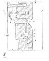
- the interface 10 between a gas turbine transition piece 12 and a first stage nozzle 14 is illustrated in cross-section.
- the transition piece 12 is formed with at least one annular slot 16 that is adapted to receive a forward, substantially vertical leg 20 of a conventional metal seal 18.
- a second leg 22 of the seal 18 extends about the transition piece and an aft, substantially horizontal leg or flange 24 is adapted to be received in an annular seal slot 26.
- An annular shim 28 may be used to provide a closer fit for the leg 24 of the seal within the seal slot 26.
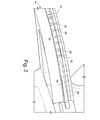
- an aft or rearward wall of the seal slot 26 is formed to provide one or more cooling cavities 29 as best seen in Figure 2 .
- a plurality of discreet cooling cavities 29 may be formed in the back wall 30 of seal slot 26, each cooling cavity feeding a single film cooling hole 32 that extends between an exterior surface 34 of the nozzle 14 and the respective cavity 29 ( Figure 1 ).
- the cooling hole or passages 32 extend at an angle in a range of about 25-30 degrees in the direction of gaspath flow and relative to the turbine rotor axis. The range is believed to provide optimum cooling effectiveness. It will be appreciated, however, that steeper angles (even up to 90 degrees) may be employed to cool other locations at higher temperatures.
- the individual cavities may have a height less than the height of the seal slot. This feature, in combination with the wall portions or partitions between the cavities, i.e., the remaining portions of back wall 30, preclude any possibility that the seal leg 24, with or without shim 28, might move into the cavities 28.
- the rear wall 30 of the seal slot 26 may be machined or otherwise formed to include a substantially continuous, annular cavity or groove 36 of a height less than the height of the back wall 30 of the seal slot 26, with a plurality of film cooling holes 38 communicating with the single annular cavity 36.
- the aft end of the seal is again precluded from entering into the cavity.
- cavity 36 could be segmented, i.e., divided, into two or more arcuate segments.
- one or more radial (or other) grooves 42 may be formed in the forward edge or face of the first stage nozzle 14 to insure cooling air to flow into the seal slot 26 and into the cooling cavities 28 (or 36), noting that there is some clearance between the seal leg 24 itself and the seal slot 26.
- the above-described arrangements provide easy access for drilling the cooling holes or passages and allow the designer to locate those cooling holes or passages at locations where existing cavities otherwise do not provide access.
- the path itself has a greater length, thereby enhancing conduction cooling within the nozzle, while at the same time, enhancing cooling air film formation along the surface of the nozzle.
- the arrangements provide a way to apply more efficient film cooling air so as to reduce flow requirements and leakages, while increasing component life and improving engine performance.
Abstract
Description
- This invention relates to gas turbine component cooling techniques and, more specifically, to a manner of feeding cooling air to film cooling holes in turbine components with seal slots.
- Gas turbine engines operate at elevated temperatures, and film cooling is widely used to protect components from the harsh high-temperature environment. Maintaining metal temperatures for gas turbine components within material limits has been addressed by many different techniques such as film cooling, impingement cooling, low conductivity coatings and heat augmentation devices such as turbulators, ribs, pin fin banks, etc.
- Film cooling is widely used in connection with gas turbine first-stage components and to a lower extent in subsequent stages. Standard practice among the industry is to feed these film cooling holes from existing cavities built into the component. This severely limits flexibility with respect to drilling holes at locations not aligned with the cavities. As a result, the designer oftentimes cannot place film cooling at locations of high level temperatures, or has to orient the cooling holes at angles that reduce the impact of the film cooling. Competitors have addressed this issue in the past by machining dedicated chambers and serpentine passages into the component. These features are only manufactured for the purpose of feeding these holes, and add extra manufacturing cost to the component.
- Specific examples in the prior art include cooling holes fed from cavities cast into the turbine sidewalls as exemplified by
U.S. Patent No. 5,344,283 . Other approaches for casting dedicated chambers into the sidewalls with the intent of feeding film cooling holes are disclosed inU.S. Patent Nos. 6,254,333 and6,210,111 . A cavity formed by seal plates in a cold side of a stage one turbine nozzle is disclosed inU.S. Patent No. 5,417,545 . A concept for machining multiple cooling holes such that they feed from the same aperture in a cold side cavity is disclosed inU.S. Patent No. 5,062,768 . The assignee of this invention presents a concept for pressurizing a seal slot with air from cooling cavities for the purpose of cooling the seal itself inU.S. Patent No. 6,340,285 . - In a first exemplary but non-limiting aspect, the present invention relates to a cooling arrangement for a turbine component having a slot along an edge thereof, the slot having a closed end formed with at least one cooling cavity, and at least one cooling passageway extending between the cavity and an external surface of the turbine component.
- In another aspect, the invention relates to a cooling arrangement for a first component of a turbine having a seal slot formed in a forward face of the component, the seal slot extending about a generally rectangular opening in said forward face and opening in a direction toward a second turbine component and adapted to receive a flange portion of a seal extending between the first component and the second component; the slot having a closed aft end formed with at least one cooling cavity provided with at least one cooling passage extending between the cavity and an external surface of the first component, and wherein said at least one cooling passage extends at an acute angle relative to a rotor axis of the turbine.
- In still another aspect, the invention relates to a method of film cooling a turbine component formed with at least one seal slot adapted to receive a seal element, the method comprising (a) forming one or more cavities at a closed end of the seal slot; (b) forming one or more cooling passages in each of the one or more cavities, the one or more cooling passages extending between the one or more cavities and a surface of the turbine component to be cooled.
- There follows a detailed description of embodiments of the invention by way of example only with reference to the accompanying drawings, in which:
-
Figure 1 is a partial side cross-section showing the interface between a gas turbine transition piece and the first-stage nozzle component, incorporating a film cooling arrangement in accordance with an exemplary but non-limiting embodiment of the invention; and -
Figure 2 is a partial front perspective view of the first-stage nozzle component shown inFigure 1 . - With reference initially to
Figure 1 , theinterface 10 between a gasturbine transition piece 12 and afirst stage nozzle 14 is illustrated in cross-section. Thetransition piece 12 is formed with at least oneannular slot 16 that is adapted to receive a forward, substantiallyvertical leg 20 of aconventional metal seal 18. Asecond leg 22 of theseal 18 extends about the transition piece and an aft, substantially horizontal leg orflange 24 is adapted to be received in anannular seal slot 26. Anannular shim 28 may be used to provide a closer fit for theleg 24 of the seal within theseal slot 26. This arrangement of theseal 18 interposed between the transition piece and first stage nozzle is conventional and needs no further description. - In accordance with a nonlimiting implementation of the invention, an aft or rearward wall of the
seal slot 26 is formed to provide one or more cooling cavities 29 as best seen inFigure 2 . In one exemplary embodiment, a plurality of discreet cooling cavities 29 may be formed in theback wall 30 ofseal slot 26, each cooling cavity feeding a singlefilm cooling hole 32 that extends between anexterior surface 34 of thenozzle 14 and the respective cavity 29 (Figure 1 ). The cooling hole orpassages 32 extend at an angle in a range of about 25-30 degrees in the direction of gaspath flow and relative to the turbine rotor axis. The range is believed to provide optimum cooling effectiveness. It will be appreciated, however, that steeper angles (even up to 90 degrees) may be employed to cool other locations at higher temperatures. Note also that the individual cavities may have a height less than the height of the seal slot. This feature, in combination with the wall portions or partitions between the cavities, i.e., the remaining portions ofback wall 30, preclude any possibility that theseal leg 24, with or withoutshim 28, might move into thecavities 28. - In a second exemplary but non-limiting embodiment, (shown in
Figure 2 ) therear wall 30 of theseal slot 26 may be machined or otherwise formed to include a substantially continuous, annular cavity orgroove 36 of a height less than the height of theback wall 30 of theseal slot 26, with a plurality offilm cooling holes 38 communicating with the singleannular cavity 36. In this embodiment, by limiting the height of the film cooling cavities to less than the height of the seal slot, the aft end of the seal is again precluded from entering into the cavity. It will be appreciated that other cavity arrangements are within the scope of this invention. For example,cavity 36 could be segmented, i.e., divided, into two or more arcuate segments. - As shown in
Figure 1 , the relative positioning of thetransition piece 12 and theseal 18 relative to thefirst stage nozzle 14 is shown under steady state conditions. Here, there is a clear flow path for compressor discharge cooling air to flow into theseal slot 26 and into the film cooling cavities 28 (or 36). It will be appreciated that in transient conditions such as start-up and shut-down, however, there may be relative movement among the components such that theseal leg 24 of theseal 18 moves toward and may actually engage the aft orback wall 30 of theseal slot 26. - If film cooling during such transient conditions is not regarded as critical, it would be of little or no consequence if the
leg 22 of theseal 18 partially or completely blocks the flow of cooling air into thefilm cooling cavities 28. On the other hand, if cooling is viewed as critical even under transient conditions, one or more radial (or other)grooves 42 may be formed in the forward edge or face of thefirst stage nozzle 14 to insure cooling air to flow into theseal slot 26 and into the cooling cavities 28 (or 36), noting that there is some clearance between theseal leg 24 itself and theseal slot 26. - The above-described arrangements provide easy access for drilling the cooling holes or passages and allow the designer to locate those cooling holes or passages at locations where existing cavities otherwise do not provide access. In addition, by angling the
cooling passages 28 as shown, the path itself has a greater length, thereby enhancing conduction cooling within the nozzle, while at the same time, enhancing cooling air film formation along the surface of the nozzle. Thus, the arrangements provide a way to apply more efficient film cooling air so as to reduce flow requirements and leakages, while increasing component life and improving engine performance. - It will also be appreciated that the cooling configurations described above are also readily employed in any stationary seal slots within the hot gas flow path of the turbine.
- While the invention has been described in connection with what is presently considered to be the most practical and preferred embodiment, it is to be understood that the invention is not to be limited to the disclosed embodiment, but on the contrary, is intended to cover various modifications and equivalent arrangements included within the spirit and scope of the appended claims.
- For completeness, various aspects of the invention are now set out in the following numbered clauses:
- 1. A cooling arrangement for a turbine component having a seal slot along an edge thereof, the slot having a closed end formed with at least one cooling cavity, and at least one cooling passageway extending between the cavity and an external surface of said turbine component.
- 2. The cooling arrangement of clause 1 wherein said at least one cooling passageway extends at an angle of between 25° and 90° relative to a direction of flow and to a rotor axis of the turbine.
- 3. The cooling arrangement of
clause 2 wherein said angle lies in a range of from 25° to 30°. - 4. The cooling arrangement of clause 1 wherein said at least one cooling cavity comprises plural discrete cavities.
- 5. The cooling arrangement of clause 1 wherein said turbine component comprises at first stage nozzle, and said seal slot opens in a direction facing a combustor transition piece and adapted to receive a flange portion of a seal extending between the first stage nozzle and the transition piece.
- 6. The cooling arrangement of clause 5 wherein said seal slot extends about a generally rectangular opening in said edge of said first stage nozzle, and wherein said at lease one cooling cavity comprises a plurality of cavities spaced from each other about said seal slot.
- 7. The cooling arrangement of clause 6 wherein some or all of said plurality of cooling cavities are provided with one of said cooling passageways.
- 8. The cooling arrangement of clause 1 wherein said seal slot extends about a generally rectangular opening in said edge of said first stage nozzle, and wherein said at least one cooling cavity comprises a single, continuous annular groove formed in said closed end of said slot.
- 9. A cooling arrangement for a first component of a turbine having a seal slot formed in a forward face of the component, the seal slot extending about a generally rectangular opening in said forward face and opening in a direction toward a second turbine component and adapted to receive a flange portion of a seal extending between the first component and the second component; the slot having a closed aft end formed with at least one cooling cavity provided with at least one cooling passage extending between the cavity and an external surface of the first component, and wherein said at least one cooling passage extends at an acute angle relative to a rotor axis of the turbine.
- 10. The cooling arrangement of clause 9 wherein said at least one cooling passageway is angled in a direction away from the second component.
- 11. The cooling arrangement of clause 9 wherein wherein said acute angle is between about 25° and 30°.
- 12. The cooling arrangement of clause 9 wherein said at least one cooling cavity comprises plural cavities, each cavity provided with one of said cooling passages.
- 13. The cooling arrangement of clause 9 wherein said at least one cooling cavity comprises a single, continuous annular groove formed about said opening.
- 14. The cooling arrangement of clause 9 and further comprising one or more grooves formed in said forward face of said first component for insuring flow of cooling air into said slot.
- 15. A method of film cooling a turbine component formed with at least one seal slot adapted to receive a seal element, the method comprising:
- (a) forming one or more cavities at a closed end of the seal slot;
- (b) forming one or more cooling passages in each of said one or more cavities, said one or more cooling passages extending between said one or more cavities and a surface of said turbine component to be cooled.
- 16. The method of clause 15 wherein said plurality of passages each extend at an angle of between 25° and 90° relative to a rotor axis of the turbine.
- 17. The method of
clause 16 wherein said angle lies in a range of from 25°-30°. - 18. The method of clause 15 wherein said seal slot extends about a forward end of a first stage nozzle, and wherein said seal element is configured to extend between said seal slot and an adjacent combustor transition piece.
- 19. The method of claim 15 wherein said one or more seal cavities comprises a plurality of discrete, circumferentially spaced cavities.
- 20. The method of clause 15 wherein said one or more cavities comprises a single, continuous annular cavity having a height less than a height of said closed end of said seal slot.
Claims (15)
- A cooling arrangement for a turbine component 14 having a seal slot 26 along an edge thereof, the slot having a closed end formed with at least one cooling cavity 29, and at least one cooling passageway 32 extending between the cavity and an external surface 34 of said turbine component 14.
- The cooling arrangement of claim 1, wherein said at least one cooling passageway 32 extends at an angle of between 25° and 90° relative to a direction of flow and to a rotor axis of the turbine.
- The cooling arrangement of claim 2, wherein said angle lies in a range of from 25° to 30°.
- The cooling arrangement of any of the preceding claims, wherein said at least one cooling cavity 29 comprises plural discrete cavities.
- The cooling arrangement of any of the preceding claims, wherein said turbine component 14 comprises at first stage nozzle, and said seal slot 26 opens in a direction facing a combustor transition piece 12 and adapted to receive a flange portion 24 of a seal 18 extending between the first stage nozzle and the transition piece.
- The cooling arrangement of any of the preceding claims, wherein said seal slot 26 extends about a generally rectangular opening in said edge of said first stage nozzle, and wherein said at lease one cooling cavity comprises 29 a plurality of cavities spaced from each other about said seal slot.
- The cooling arrangement of claim 6, wherein some or all of said plurality of cooling cavities 29 are provided with one of said cooling passageways 32.
- The cooling arrangement of any of the preceding claims, wherein said seal slot 26 extends about a generally rectangular opening in said edge of said first stage nozzle, and wherein said at least one cooling cavity comprises a single, continuous annular groove 36 formed in said closed end of said slot.
- A cooling arrangement for a first component 14 of a turbine having a seal slot 26 formed in a forward face of the component, the seal slot 26 extending about a generally rectangular opening in said forward face and opening in a direction toward a second turbine component 12 and adapted to receive a flange portion 24 of a seal 18 extending between the first component 14 and the second component 12; the slot having a closed aft end formed with at least one cooling cavity 29 provided with at least one cooling passage 32 extending between the cavity and an external surface 34 of the first component, and wherein said at least one cooling passage 32 extends at an acute angle relative to a rotor axis of the turbine.
- The cooling arrangement of claim 9, wherein said at least one cooling passage 32 is angled in a direction away from the second component.
- The cooling arrangement of claim 9 or 10, wherein said acute angle is between about 25° and 30°.
- The cooling arrangement of any of claims 9 to 11, wherein said at least one cooling cavity 29 comprises plural cavities, each cavity provided with one of said cooling passages 32.
- The cooling arrangement of any of claims 9 to 11, wherein said at least one cooling cavity comprises a single, continuous annular groove 36 formed about said opening.
- The cooling arrangement of any of claims 9 to 13, and further comprising one or more grooves 42 formed in said forward face of said first component 14 for insuring flow of cooling air into said slot.
- A method of film cooling a turbine component 14 formed with at least one seal slot 26 adapted to receive a seal element, the method comprising:(a) forming one or more cavities 29 at a closed end of the seal slot;(b) forming one or more cooling passages 32 in each of said one or more cavities, said one or more cooling passages extending between said one or more cavities and a surface 34 of said turbine component to be cooled.
Applications Claiming Priority (1)
| Application Number | Priority Date | Filing Date | Title |
|---|---|---|---|
| US12/415,372 US8092159B2 (en) | 2009-03-31 | 2009-03-31 | Feeding film cooling holes from seal slots |
Publications (3)
| Publication Number | Publication Date |
|---|---|
| EP2239418A2 true EP2239418A2 (en) | 2010-10-13 |
| EP2239418A3 EP2239418A3 (en) | 2012-08-15 |
| EP2239418B1 EP2239418B1 (en) | 2014-09-17 |
Family
ID=42236586
Family Applications (1)
| Application Number | Title | Priority Date | Filing Date |
|---|---|---|---|
| EP10158249.2A Not-in-force EP2239418B1 (en) | 2009-03-31 | 2010-03-29 | Feeding Film Cooling Holes from Seal Slots |
Country Status (4)
| Country | Link |
|---|---|
| US (1) | US8092159B2 (en) |
| EP (1) | EP2239418B1 (en) |
| JP (1) | JP5094901B2 (en) |
| CN (1) | CN101922353B (en) |
Cited By (2)
| Publication number | Priority date | Publication date | Assignee | Title |
|---|---|---|---|---|
| EP2365188A1 (en) * | 2010-03-03 | 2011-09-14 | General Electric Company | Cooling gas turbine components with seal slot channels |
| WO2014146954A1 (en) * | 2013-03-21 | 2014-09-25 | Siemens Aktiengesellschaft | Sealing element for sealing a gap |
Families Citing this family (15)
| Publication number | Priority date | Publication date | Assignee | Title |
|---|---|---|---|---|
| US9255484B2 (en) * | 2011-03-16 | 2016-02-09 | General Electric Company | Aft frame and method for cooling aft frame |
| US9879555B2 (en) * | 2011-05-20 | 2018-01-30 | Siemens Energy, Inc. | Turbine combustion system transition seals |
| US9115585B2 (en) * | 2011-06-06 | 2015-08-25 | General Electric Company | Seal assembly for gas turbine |
| FR2986836B1 (en) * | 2012-02-09 | 2016-01-01 | Snecma | ANTI-WEAR ANNULAR TOOL FOR A TURBOMACHINE |
| US9115808B2 (en) * | 2012-02-13 | 2015-08-25 | General Electric Company | Transition piece seal assembly for a turbomachine |
| US9010127B2 (en) * | 2012-03-02 | 2015-04-21 | General Electric Company | Transition piece aft frame assembly having a heat shield |
| JP6016655B2 (en) * | 2013-02-04 | 2016-10-26 | 三菱日立パワーシステムズ株式会社 | Gas turbine tail tube seal and gas turbine |
| CN107075961B (en) * | 2014-10-28 | 2020-01-03 | 西门子公司 | Seal assembly between a transition duct and a first row of vane assemblies for use in a turbine engine |
| US10683766B2 (en) * | 2016-07-29 | 2020-06-16 | Siemens Energy, Inc. | Static wear seals for a combustor transition |
| GB201614711D0 (en) * | 2016-08-31 | 2016-10-12 | Rolls Royce Plc | Axial flow machine |
| CN107143385B (en) * | 2017-06-26 | 2019-02-15 | 中国科学院工程热物理研究所 | A kind of gas turbine guider leading edge installation side structure and the gas turbine with it |
| KR101965502B1 (en) * | 2017-09-29 | 2019-04-03 | 두산중공업 주식회사 | Conjunction assembly and gas turbine comprising the same |
| KR20190101089A (en) * | 2018-02-22 | 2019-08-30 | 현대자동차주식회사 | Piston ring for engine |
| JP6966354B2 (en) * | 2018-02-28 | 2021-11-17 | 三菱パワー株式会社 | Gas turbine combustor |
| US10968762B2 (en) * | 2018-11-19 | 2021-04-06 | General Electric Company | Seal assembly for a turbo machine |
Citations (6)
| Publication number | Priority date | Publication date | Assignee | Title |
|---|---|---|---|---|
| US5062768A (en) | 1988-12-23 | 1991-11-05 | Rolls-Royce Plc | Cooled turbomachinery components |
| US5344283A (en) | 1993-01-21 | 1994-09-06 | United Technologies Corporation | Turbine vane having dedicated inner platform cooling |
| US5417545A (en) | 1993-03-11 | 1995-05-23 | Rolls-Royce Plc | Cooled turbine nozzle assembly and a method of calculating the diameters of cooling holes for use in such an assembly |
| US6210111B1 (en) | 1998-12-21 | 2001-04-03 | United Technologies Corporation | Turbine blade with platform cooling |
| US6254333B1 (en) | 1999-08-02 | 2001-07-03 | United Technologies Corporation | Method for forming a cooling passage and for cooling a turbine section of a rotary machine |
| US6340285B1 (en) | 2000-06-08 | 2002-01-22 | General Electric Company | End rail cooling for combined high and low pressure turbine shroud |
Family Cites Families (20)
| Publication number | Priority date | Publication date | Assignee | Title |
|---|---|---|---|---|
| GB938189A (en) * | 1960-10-29 | 1963-10-02 | Ruston & Hornsby Ltd | Improvements in the construction of turbine and compressor blade elements |
| US4157232A (en) * | 1977-10-31 | 1979-06-05 | General Electric Company | Turbine shroud support |
| US4902198A (en) * | 1988-08-31 | 1990-02-20 | Westinghouse Electric Corp. | Apparatus for film cooling of turbine van shrouds |
| US5503528A (en) * | 1993-12-27 | 1996-04-02 | Solar Turbines Incorporated | Rim seal for turbine wheel |
| JP3285793B2 (en) * | 1997-06-30 | 2002-05-27 | 三菱重工業株式会社 | Gas turbine rotor |
| US6343911B1 (en) * | 2000-04-05 | 2002-02-05 | General Electric Company | Side wall cooling for nozzle segments for a gas turbine |
| US6412268B1 (en) * | 2000-04-06 | 2002-07-02 | General Electric Company | Cooling air recycling for gas turbine transition duct end frame and related method |
| US6547257B2 (en) * | 2001-05-04 | 2003-04-15 | General Electric Company | Combination transition piece floating cloth seal and stage 1 turbine nozzle flexible sealing element |
| GB2378730B (en) * | 2001-08-18 | 2005-03-16 | Rolls Royce Plc | Cooled segments surrounding turbine blades |
| US6860108B2 (en) * | 2003-01-22 | 2005-03-01 | Mitsubishi Heavy Industries, Ltd. | Gas turbine tail tube seal and gas turbine using the same |
| DE10330471A1 (en) * | 2003-07-05 | 2005-02-03 | Alstom Technology Ltd | Device for separating foreign particles from the cooling air that can be fed to the moving blades of a turbine |
| US6942445B2 (en) * | 2003-12-04 | 2005-09-13 | Honeywell International Inc. | Gas turbine cooled shroud assembly with hot gas ingestion suppression |
| US7097417B2 (en) * | 2004-02-09 | 2006-08-29 | Siemens Westinghouse Power Corporation | Cooling system for an airfoil vane |
| US7217081B2 (en) * | 2004-10-15 | 2007-05-15 | Siemens Power Generation, Inc. | Cooling system for a seal for turbine vane shrouds |
| JP4668636B2 (en) * | 2005-02-04 | 2011-04-13 | 株式会社日立製作所 | Gas turbine combustor |
| GB0513468D0 (en) * | 2005-07-01 | 2005-08-10 | Rolls Royce Plc | A mounting arrangement for turbine blades |
| US7784264B2 (en) * | 2006-08-03 | 2010-08-31 | Siemens Energy, Inc. | Slidable spring-loaded transition-to-turbine seal apparatus and heat-shielding system, comprising the seal, at transition/turbine junction of a gas turbine engine |
| US7832986B2 (en) * | 2007-03-07 | 2010-11-16 | Honeywell International Inc. | Multi-alloy turbine rotors and methods of manufacturing the rotors |
| JP4690353B2 (en) * | 2007-03-09 | 2011-06-01 | 株式会社日立製作所 | Gas turbine sealing device |
| US8277177B2 (en) * | 2009-01-19 | 2012-10-02 | Siemens Energy, Inc. | Fluidic rim seal system for turbine engines |
-
2009
- 2009-03-31 US US12/415,372 patent/US8092159B2/en not_active Expired - Fee Related
-
2010
- 2010-03-25 JP JP2010069256A patent/JP5094901B2/en not_active Expired - Fee Related
- 2010-03-29 EP EP10158249.2A patent/EP2239418B1/en not_active Not-in-force
- 2010-03-31 CN CN2010101569416A patent/CN101922353B/en not_active Expired - Fee Related
Patent Citations (6)
| Publication number | Priority date | Publication date | Assignee | Title |
|---|---|---|---|---|
| US5062768A (en) | 1988-12-23 | 1991-11-05 | Rolls-Royce Plc | Cooled turbomachinery components |
| US5344283A (en) | 1993-01-21 | 1994-09-06 | United Technologies Corporation | Turbine vane having dedicated inner platform cooling |
| US5417545A (en) | 1993-03-11 | 1995-05-23 | Rolls-Royce Plc | Cooled turbine nozzle assembly and a method of calculating the diameters of cooling holes for use in such an assembly |
| US6210111B1 (en) | 1998-12-21 | 2001-04-03 | United Technologies Corporation | Turbine blade with platform cooling |
| US6254333B1 (en) | 1999-08-02 | 2001-07-03 | United Technologies Corporation | Method for forming a cooling passage and for cooling a turbine section of a rotary machine |
| US6340285B1 (en) | 2000-06-08 | 2002-01-22 | General Electric Company | End rail cooling for combined high and low pressure turbine shroud |
Cited By (3)
| Publication number | Priority date | Publication date | Assignee | Title |
|---|---|---|---|---|
| EP2365188A1 (en) * | 2010-03-03 | 2011-09-14 | General Electric Company | Cooling gas turbine components with seal slot channels |
| US8371800B2 (en) | 2010-03-03 | 2013-02-12 | General Electric Company | Cooling gas turbine components with seal slot channels |
| WO2014146954A1 (en) * | 2013-03-21 | 2014-09-25 | Siemens Aktiengesellschaft | Sealing element for sealing a gap |
Also Published As
| Publication number | Publication date |
|---|---|
| CN101922353B (en) | 2013-11-20 |
| US8092159B2 (en) | 2012-01-10 |
| JP5094901B2 (en) | 2012-12-12 |
| EP2239418A3 (en) | 2012-08-15 |
| EP2239418B1 (en) | 2014-09-17 |
| CN101922353A (en) | 2010-12-22 |
| JP2010242750A (en) | 2010-10-28 |
| US20100247286A1 (en) | 2010-09-30 |
Similar Documents
| Publication | Publication Date | Title |
|---|---|---|
| EP2239418B1 (en) | Feeding Film Cooling Holes from Seal Slots | |
| US9797261B2 (en) | Internal cooling of engine components | |
| US8727724B2 (en) | Turbine bucket having a radial cooling hole | |
| EP2351908B1 (en) | Turbine blade | |
| EP2863015B1 (en) | Turbine rotor blade and corresponding manufacturing method | |
| CN106609682B (en) | Turbine bucket and corresponding turbine | |
| US20090202339A1 (en) | Platform cooling structure for gas turbine moving blade | |
| EP3163023B1 (en) | Turbine bucket with cooling passage in the shroud | |
| US8511995B1 (en) | Turbine blade with platform cooling | |
| EP2597264B1 (en) | Aerofoil cooling arrangement | |
| US10458291B2 (en) | Cover plate for a component of a gas turbine engine | |
| US8961136B1 (en) | Turbine airfoil with film cooling hole | |
| EP2867502B1 (en) | Gas turbine engine component having platform cooling channel | |
| US8317476B1 (en) | Turbine blade with tip cooling circuit | |
| US20150104327A1 (en) | Turbine rotor blades with tip portion parapet wall cavities | |
| US9562437B2 (en) | Turbine blade airfoils including film cooling systems, and methods for forming an improved film cooled airfoil of a turbine blade | |
| US20180073370A1 (en) | Turbine blade cooling | |
| US8444375B2 (en) | Cooled blade for a gas turbine, method for producing such a blade, and gas turbine having such a blade | |
| EP2584151A2 (en) | Sealing system for a turbine rotor blade and corresponding gas turbine engine | |
| JP2007211618A (en) | Gas turbine | |
| KR20160074423A (en) | Gas turbine vane | |
| US8388304B2 (en) | Turbine airfoil cooling system with high density section of endwall cooling channels | |
| CN114585802A (en) | Turbine blade, method of manufacturing a turbine blade and method of refurbishing a turbine blade | |
| EP3677750B1 (en) | Gas turbine engine component with a trailing edge discharge slot | |
| KR20150130870A (en) | Blade tip cooling structure for gas-turbine |
Legal Events
| Date | Code | Title | Description |
|---|---|---|---|
| PUAI | Public reference made under article 153(3) epc to a published international application that has entered the european phase |
Free format text: ORIGINAL CODE: 0009012 |
|
| AK | Designated contracting states |
Kind code of ref document: A2 Designated state(s): AT BE BG CH CY CZ DE DK EE ES FI FR GB GR HR HU IE IS IT LI LT LU LV MC MK MT NL NO PL PT RO SE SI SK SM TR |
|
| AX | Request for extension of the european patent |
Extension state: AL BA ME RS |
|
| PUAL | Search report despatched |
Free format text: ORIGINAL CODE: 0009013 |
|
| AK | Designated contracting states |
Kind code of ref document: A3 Designated state(s): AT BE BG CH CY CZ DE DK EE ES FI FR GB GR HR HU IE IS IT LI LT LU LV MC MK MT NL NO PL PT RO SE SI SK SM TR |
|
| AX | Request for extension of the european patent |
Extension state: AL BA ME RS |
|
| RIC1 | Information provided on ipc code assigned before grant |
Ipc: F01D 11/00 20060101ALI20120712BHEP Ipc: F01D 9/02 20060101ALI20120712BHEP Ipc: F01D 5/18 20060101AFI20120712BHEP |
|
| 17P | Request for examination filed |
Effective date: 20130215 |
|
| 17Q | First examination report despatched |
Effective date: 20130724 |
|
| GRAP | Despatch of communication of intention to grant a patent |
Free format text: ORIGINAL CODE: EPIDOSNIGR1 |
|
| INTG | Intention to grant announced |
Effective date: 20140612 |
|
| GRAS | Grant fee paid |
Free format text: ORIGINAL CODE: EPIDOSNIGR3 |
|
| GRAA | (expected) grant |
Free format text: ORIGINAL CODE: 0009210 |
|
| AK | Designated contracting states |
Kind code of ref document: B1 Designated state(s): AT BE BG CH CY CZ DE DK EE ES FI FR GB GR HR HU IE IS IT LI LT LU LV MC MK MT NL NO PL PT RO SE SI SK SM TR |
|
| REG | Reference to a national code |
Ref country code: GB Ref legal event code: FG4D |
|
| REG | Reference to a national code |
Ref country code: CH Ref legal event code: EP |
|
| REG | Reference to a national code |
Ref country code: IE Ref legal event code: FG4D |
|
| REG | Reference to a national code |
Ref country code: AT Ref legal event code: REF Ref document number: 687812 Country of ref document: AT Kind code of ref document: T Effective date: 20141015 |
|
| REG | Reference to a national code |
Ref country code: DE Ref legal event code: R096 Ref document number: 602010018968 Country of ref document: DE Effective date: 20141030 |
|
| PG25 | Lapsed in a contracting state [announced via postgrant information from national office to epo] |
Ref country code: SE Free format text: LAPSE BECAUSE OF FAILURE TO SUBMIT A TRANSLATION OF THE DESCRIPTION OR TO PAY THE FEE WITHIN THE PRESCRIBED TIME-LIMIT Effective date: 20140917 Ref country code: LT Free format text: LAPSE BECAUSE OF FAILURE TO SUBMIT A TRANSLATION OF THE DESCRIPTION OR TO PAY THE FEE WITHIN THE PRESCRIBED TIME-LIMIT Effective date: 20140917 Ref country code: NO Free format text: LAPSE BECAUSE OF FAILURE TO SUBMIT A TRANSLATION OF THE DESCRIPTION OR TO PAY THE FEE WITHIN THE PRESCRIBED TIME-LIMIT Effective date: 20141217 Ref country code: FI Free format text: LAPSE BECAUSE OF FAILURE TO SUBMIT A TRANSLATION OF THE DESCRIPTION OR TO PAY THE FEE WITHIN THE PRESCRIBED TIME-LIMIT Effective date: 20140917 Ref country code: GR Free format text: LAPSE BECAUSE OF FAILURE TO SUBMIT A TRANSLATION OF THE DESCRIPTION OR TO PAY THE FEE WITHIN THE PRESCRIBED TIME-LIMIT Effective date: 20141218 |
|
| REG | Reference to a national code |
Ref country code: NL Ref legal event code: VDEP Effective date: 20140917 |
|
| REG | Reference to a national code |
Ref country code: LT Ref legal event code: MG4D |
|
| PG25 | Lapsed in a contracting state [announced via postgrant information from national office to epo] |
Ref country code: LV Free format text: LAPSE BECAUSE OF FAILURE TO SUBMIT A TRANSLATION OF THE DESCRIPTION OR TO PAY THE FEE WITHIN THE PRESCRIBED TIME-LIMIT Effective date: 20140917 Ref country code: CY Free format text: LAPSE BECAUSE OF FAILURE TO SUBMIT A TRANSLATION OF THE DESCRIPTION OR TO PAY THE FEE WITHIN THE PRESCRIBED TIME-LIMIT Effective date: 20140917 Ref country code: HR Free format text: LAPSE BECAUSE OF FAILURE TO SUBMIT A TRANSLATION OF THE DESCRIPTION OR TO PAY THE FEE WITHIN THE PRESCRIBED TIME-LIMIT Effective date: 20140917 |
|
| REG | Reference to a national code |
Ref country code: AT Ref legal event code: MK05 Ref document number: 687812 Country of ref document: AT Kind code of ref document: T Effective date: 20140917 |
|
| PG25 | Lapsed in a contracting state [announced via postgrant information from national office to epo] |
Ref country code: NL Free format text: LAPSE BECAUSE OF FAILURE TO SUBMIT A TRANSLATION OF THE DESCRIPTION OR TO PAY THE FEE WITHIN THE PRESCRIBED TIME-LIMIT Effective date: 20140917 |
|
| PG25 | Lapsed in a contracting state [announced via postgrant information from national office to epo] |
Ref country code: IS Free format text: LAPSE BECAUSE OF FAILURE TO SUBMIT A TRANSLATION OF THE DESCRIPTION OR TO PAY THE FEE WITHIN THE PRESCRIBED TIME-LIMIT Effective date: 20150117 Ref country code: CZ Free format text: LAPSE BECAUSE OF FAILURE TO SUBMIT A TRANSLATION OF THE DESCRIPTION OR TO PAY THE FEE WITHIN THE PRESCRIBED TIME-LIMIT Effective date: 20140917 Ref country code: PT Free format text: LAPSE BECAUSE OF FAILURE TO SUBMIT A TRANSLATION OF THE DESCRIPTION OR TO PAY THE FEE WITHIN THE PRESCRIBED TIME-LIMIT Effective date: 20150119 Ref country code: EE Free format text: LAPSE BECAUSE OF FAILURE TO SUBMIT A TRANSLATION OF THE DESCRIPTION OR TO PAY THE FEE WITHIN THE PRESCRIBED TIME-LIMIT Effective date: 20140917 Ref country code: RO Free format text: LAPSE BECAUSE OF FAILURE TO SUBMIT A TRANSLATION OF THE DESCRIPTION OR TO PAY THE FEE WITHIN THE PRESCRIBED TIME-LIMIT Effective date: 20140917 Ref country code: SK Free format text: LAPSE BECAUSE OF FAILURE TO SUBMIT A TRANSLATION OF THE DESCRIPTION OR TO PAY THE FEE WITHIN THE PRESCRIBED TIME-LIMIT Effective date: 20140917 Ref country code: ES Free format text: LAPSE BECAUSE OF FAILURE TO SUBMIT A TRANSLATION OF THE DESCRIPTION OR TO PAY THE FEE WITHIN THE PRESCRIBED TIME-LIMIT Effective date: 20140917 |
|
| PG25 | Lapsed in a contracting state [announced via postgrant information from national office to epo] |
Ref country code: AT Free format text: LAPSE BECAUSE OF FAILURE TO SUBMIT A TRANSLATION OF THE DESCRIPTION OR TO PAY THE FEE WITHIN THE PRESCRIBED TIME-LIMIT Effective date: 20140917 Ref country code: PL Free format text: LAPSE BECAUSE OF FAILURE TO SUBMIT A TRANSLATION OF THE DESCRIPTION OR TO PAY THE FEE WITHIN THE PRESCRIBED TIME-LIMIT Effective date: 20140917 |
|
| REG | Reference to a national code |
Ref country code: DE Ref legal event code: R097 Ref document number: 602010018968 Country of ref document: DE |
|
| PLBE | No opposition filed within time limit |
Free format text: ORIGINAL CODE: 0009261 |
|
| STAA | Information on the status of an ep patent application or granted ep patent |
Free format text: STATUS: NO OPPOSITION FILED WITHIN TIME LIMIT |
|
| PG25 | Lapsed in a contracting state [announced via postgrant information from national office to epo] |
Ref country code: DK Free format text: LAPSE BECAUSE OF FAILURE TO SUBMIT A TRANSLATION OF THE DESCRIPTION OR TO PAY THE FEE WITHIN THE PRESCRIBED TIME-LIMIT Effective date: 20140917 |
|
| 26N | No opposition filed |
Effective date: 20150618 |
|
| PG25 | Lapsed in a contracting state [announced via postgrant information from national office to epo] |
Ref country code: IT Free format text: LAPSE BECAUSE OF FAILURE TO SUBMIT A TRANSLATION OF THE DESCRIPTION OR TO PAY THE FEE WITHIN THE PRESCRIBED TIME-LIMIT Effective date: 20140917 |
|
| PG25 | Lapsed in a contracting state [announced via postgrant information from national office to epo] |
Ref country code: MC Free format text: LAPSE BECAUSE OF FAILURE TO SUBMIT A TRANSLATION OF THE DESCRIPTION OR TO PAY THE FEE WITHIN THE PRESCRIBED TIME-LIMIT Effective date: 20140917 Ref country code: LU Free format text: LAPSE BECAUSE OF FAILURE TO SUBMIT A TRANSLATION OF THE DESCRIPTION OR TO PAY THE FEE WITHIN THE PRESCRIBED TIME-LIMIT Effective date: 20150329 |
|
| REG | Reference to a national code |
Ref country code: CH Ref legal event code: PL |
|
| GBPC | Gb: european patent ceased through non-payment of renewal fee |
Effective date: 20150329 |
|
| PG25 | Lapsed in a contracting state [announced via postgrant information from national office to epo] |
Ref country code: SI Free format text: LAPSE BECAUSE OF FAILURE TO SUBMIT A TRANSLATION OF THE DESCRIPTION OR TO PAY THE FEE WITHIN THE PRESCRIBED TIME-LIMIT Effective date: 20140917 |
|
| REG | Reference to a national code |
Ref country code: FR Ref legal event code: ST Effective date: 20151130 |
|
| REG | Reference to a national code |
Ref country code: IE Ref legal event code: MM4A |
|
| PG25 | Lapsed in a contracting state [announced via postgrant information from national office to epo] |
Ref country code: CH Free format text: LAPSE BECAUSE OF NON-PAYMENT OF DUE FEES Effective date: 20150331 Ref country code: LI Free format text: LAPSE BECAUSE OF NON-PAYMENT OF DUE FEES Effective date: 20150331 Ref country code: IE Free format text: LAPSE BECAUSE OF NON-PAYMENT OF DUE FEES Effective date: 20150329 Ref country code: GB Free format text: LAPSE BECAUSE OF NON-PAYMENT OF DUE FEES Effective date: 20150329 |
|
| PG25 | Lapsed in a contracting state [announced via postgrant information from national office to epo] |
Ref country code: FR Free format text: LAPSE BECAUSE OF NON-PAYMENT OF DUE FEES Effective date: 20150331 |
|
| PG25 | Lapsed in a contracting state [announced via postgrant information from national office to epo] |
Ref country code: MT Free format text: LAPSE BECAUSE OF FAILURE TO SUBMIT A TRANSLATION OF THE DESCRIPTION OR TO PAY THE FEE WITHIN THE PRESCRIBED TIME-LIMIT Effective date: 20140917 |
|
| PG25 | Lapsed in a contracting state [announced via postgrant information from national office to epo] |
Ref country code: BG Free format text: LAPSE BECAUSE OF FAILURE TO SUBMIT A TRANSLATION OF THE DESCRIPTION OR TO PAY THE FEE WITHIN THE PRESCRIBED TIME-LIMIT Effective date: 20140917 Ref country code: SM Free format text: LAPSE BECAUSE OF FAILURE TO SUBMIT A TRANSLATION OF THE DESCRIPTION OR TO PAY THE FEE WITHIN THE PRESCRIBED TIME-LIMIT Effective date: 20140917 Ref country code: HU Free format text: LAPSE BECAUSE OF FAILURE TO SUBMIT A TRANSLATION OF THE DESCRIPTION OR TO PAY THE FEE WITHIN THE PRESCRIBED TIME-LIMIT; INVALID AB INITIO Effective date: 20100329 |
|
| PGFP | Annual fee paid to national office [announced via postgrant information from national office to epo] |
Ref country code: DE Payment date: 20170329 Year of fee payment: 8 |
|
| PG25 | Lapsed in a contracting state [announced via postgrant information from national office to epo] |
Ref country code: TR Free format text: LAPSE BECAUSE OF FAILURE TO SUBMIT A TRANSLATION OF THE DESCRIPTION OR TO PAY THE FEE WITHIN THE PRESCRIBED TIME-LIMIT Effective date: 20140917 |
|
| PG25 | Lapsed in a contracting state [announced via postgrant information from national office to epo] |
Ref country code: BE Free format text: LAPSE BECAUSE OF FAILURE TO SUBMIT A TRANSLATION OF THE DESCRIPTION OR TO PAY THE FEE WITHIN THE PRESCRIBED TIME-LIMIT Effective date: 20140917 |
|
| PG25 | Lapsed in a contracting state [announced via postgrant information from national office to epo] |
Ref country code: MK Free format text: LAPSE BECAUSE OF FAILURE TO SUBMIT A TRANSLATION OF THE DESCRIPTION OR TO PAY THE FEE WITHIN THE PRESCRIBED TIME-LIMIT Effective date: 20140917 |
|
| REG | Reference to a national code |
Ref country code: DE Ref legal event code: R119 Ref document number: 602010018968 Country of ref document: DE |
|
| PG25 | Lapsed in a contracting state [announced via postgrant information from national office to epo] |
Ref country code: DE Free format text: LAPSE BECAUSE OF NON-PAYMENT OF DUE FEES Effective date: 20181002 |