EP2239411B1 - Bit-run nominal seat protector and method of operating same - Google Patents
Bit-run nominal seat protector and method of operating same Download PDFInfo
- Publication number
- EP2239411B1 EP2239411B1 EP10157124.8A EP10157124A EP2239411B1 EP 2239411 B1 EP2239411 B1 EP 2239411B1 EP 10157124 A EP10157124 A EP 10157124A EP 2239411 B1 EP2239411 B1 EP 2239411B1
- Authority
- EP
- European Patent Office
- Prior art keywords
- nsp
- running tool
- wear bushing
- wear
- wellbore
- Prior art date
- Legal status (The legal status is an assumption and is not a legal conclusion. Google has not performed a legal analysis and makes no representation as to the accuracy of the status listed.)
- Active
Links
Images



Classifications
-
- E—FIXED CONSTRUCTIONS
- E21—EARTH OR ROCK DRILLING; MINING
- E21B—EARTH OR ROCK DRILLING; OBTAINING OIL, GAS, WATER, SOLUBLE OR MELTABLE MATERIALS OR A SLURRY OF MINERALS FROM WELLS
- E21B17/00—Drilling rods or pipes; Flexible drill strings; Kellies; Drill collars; Sucker rods; Cables; Casings; Tubings
- E21B17/10—Wear protectors; Centralising devices, e.g. stabilisers
- E21B17/12—Devices for placing or drawing out wear protectors
-
- E—FIXED CONSTRUCTIONS
- E21—EARTH OR ROCK DRILLING; MINING
- E21B—EARTH OR ROCK DRILLING; OBTAINING OIL, GAS, WATER, SOLUBLE OR MELTABLE MATERIALS OR A SLURRY OF MINERALS FROM WELLS
- E21B17/00—Drilling rods or pipes; Flexible drill strings; Kellies; Drill collars; Sucker rods; Cables; Casings; Tubings
- E21B17/10—Wear protectors; Centralising devices, e.g. stabilisers
- E21B17/1007—Wear protectors; Centralising devices, e.g. stabilisers for the internal surface of a pipe, e.g. wear bushings for underwater well-heads
-
- E—FIXED CONSTRUCTIONS
- E21—EARTH OR ROCK DRILLING; MINING
- E21B—EARTH OR ROCK DRILLING; OBTAINING OIL, GAS, WATER, SOLUBLE OR MELTABLE MATERIALS OR A SLURRY OF MINERALS FROM WELLS
- E21B33/00—Sealing or packing boreholes or wells
- E21B33/02—Surface sealing or packing
- E21B33/03—Well heads; Setting-up thereof
- E21B33/068—Well heads; Setting-up thereof having provision for introducing objects or fluids into, or removing objects from, wells
Definitions
- the present invention relates in general to an improved wear bushing system, and in particular to an improved bit-run wear bushing and tool and method of operation.
- US 4 674 576 A discloses a running tool comprising a stem with a torque ring, a running nut, an engagement sleeve and a lock ring to releasably connect and support a casing hanger, a two piece wear bushing and a packoff assembly thereon.
- US 4 886 121 discloses a wellhead housing structure which utilizes identical units of a wellhead housing each with a flexible bowl hanger support ring.
- a wear bushing or seat protector is used in drilling applications to protect the inner profiles of the various components in the wellhead.
- wear bushings typically have been run or lowered down to the wellhead on a separate trip.
- One type of bit run wear bushing is held to a tool via shear pins.
- This bit run wear bushing has an internal ledge with a reduced inner diameter for retrieval.
- the bit run wear bushing is not suitable to protect all of the seats inside a wellbore. Thus an improved bit run wear bushing would be desirable.
- the present invention provides a wellbore surface protection apparatus as defined in claim 1 and a method for protecting a surface inside a wellbore as defined in claim 10.
- a running tool is attached to a drill string.
- One or more seat protectors are attached to the running tool. When the drill string is lowered into the wellbore to perform drilling operations, the seat protectors detach from the running tool as the tool passes through the surface to be protected. The seat protectors remain in place during the drilling operation, and are then retrieved when the drill string is withdrawn from the wellbore.
- Figure 1 is a sectional view showing the inside of a wellbore prior to installing a wear bushing.
- Figure 2 is a sectional view showing the wellbore of Figure 1 with a lower casing string installed, prior to installing a wear bushing.
- Figure 3 is a sectional view showing the wellbore of Figure 1 with a lower and middle casing string installed, prior to installing a wear bushing.
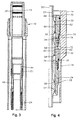
- Figure 4 is a quarter sectional view of a set of seat protectors in the wellhead housing of Figure 1 .
- Figure 5 is a quarter sectional detail view showing a set of seat protectors in the wellhead housing of Figure 1 .
- Figures 6A and 6B are quarter sectional views showing the smart latch device of the seat protectors of Figure 4 .
- Figure 7 is a quarter sectional view of two of the seat protectors of Figure 4 at the intermediate landing sub of Figure 1 .
- Figure 8 is a quarter sectional view of one of the seat protectors of Figure 4 at the lower landing sub of Figure 1 .
- Figure 9 is a side view of the running tool of Figure 4 .
- Figure 10 is a sectional view of the seat protectors of Figure 4 installed in the wellbore of Figure 1 .
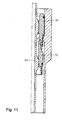
- Figure 11 is a quarter sectional view of an alternative configuration of the seat protectors of Figure 4 .
- a wellhead 10 is presented, and represented generally by reference numeral 10.
- the illustrated wellhead 10 has a tubular outer wellhead housing 12 with an inner bore.
- a string of outer casing or conductor pipe 13 is attached to outer wellhead housing 10.
- the inner bore concentrically accepts an inner wellhead housing 14 that is supported by an inner wellhead housing support 16 on the outer wellhead housing 12.
- the inner wellhead housing support 16 is a shoulder on the outer wellhead housing 12 that slopes downward and inward, and mates with the inner wellhead housing 14.
- a section of casing 18 is suspended from the inner wellhead housing 14 of the wellhead 10.
- the upper casing 18 is a nominal 22" casing that may extend, for example, several thousand feet down to a first landing sub 20.
- a middle casing 22 extends downward to a second landing sub 24.
- a lower casing 26 extends downward from the second landing sub 24.
- a nominal seat protector is a type of wear bushing that may be inserted into a wellhead component to protect the bore of the wellhead component from damage as drill bits, drill pipe, etc., are passed back and forth though the bore of the wellhead component.
- an NSP may be deployed within the inner wellhead housing 14 and landing subs 20, 24 to protect bore surfaces of the inner wellhead housing and/or landing subs.
- a first NSP 30 is illustrated with dashed lines within the inner wellhead housing 14.
- a second NSP 32 is provided to protect bore surfaces of the first landing sub 20.
- a third NSP 34 is presented in the illustrated embodiment to protect bore surfaces of the second landing sub 24.
- the minimum inner diameter of the landing shoulder in wellhead housing 14 is greater than the minimum inner diameter of middle landing sub 20.
- the minimum inner diameter of middle landing sub 20 is greater than the minimum inner diameter of lower landing sub 24.
- the outer diameter of first NSP 30 is greater than the outer diameter of second NSP 32, which is greater than the outer diameter of third NSP 34.
- the NSPs are bit-run NSPs that are deployed by a running tool deployed as part of a drill string having a drill bit at the bottom (not shown in Figure 1 ).
- the running tool is used to install all three NSPs 30, 32, 34 on a single trip of the drill string into the well.
- the NSPs 30, 32, 34 are attached to the running tool and sequentially released as the drill string is lowered down the wellbore.
- the second NSP 32 and the third NSP 34 pass through the wellhead 12.
- the first NSP 30 engages the inner wellhead housing 14 and detaches from the second NSP 32 and the running tool, thereby remaining in the inner wellhead housing 14.
- the portions of the drill string above the inner wellhead housing 14 continue to descend through the center of the first NSP 30.
- the third NSP 34 passes through the first landing sub 20.
- the second NSP 32 engages the first landing sub 20 and detaches from the third NSP 34 and the running tool, remaining in place inside the first landing sub 20.
- the drill string continues to descend through the second NSP 32.
- the third NSP 34 engages the second landing sub 24 and detaches from the running tool, remaining in place to protect the second landing sub as the drill string continues to descend through the third NSP 34.
- the first NSP 30 is a 22" NSP
- the second NSP 32 is a 16" NSP
- the third NSP 34 is an 18" NSP.
- the dimensions 22", 16", and 18" correspond to the nominal size in inches of the pipe which will eventually hang on the inner wellhead housing 14 and the landing subs, respectively.
- NSPs having other diameters may be used.
- Any number of NSPs may be deployed on a single trip, including, for example, two, three, four, or more.
- the NSPs may be sized to fit on any size seat within the wellhead and may be used with any size pipe.
- the lower landing sub 24 is a nominal 18" landing sub, which supports a nominal 18" lower casing hanger 40.
- a medium diameter casing 42 is suspended from the lower casing hanger 40. The medium diameter casing 42 may extend several thousand feet below the lower landing sub 24.
- the first NSP 30 may be used to protect the inner wellhead housing 14 and the second NSP 32 may be used to protect the first landing sub 20 after the casing hanger 40 is installed in the second landing sub 24.
- the operator has drilled deeper through casing 42 and retrieved the running tool and NSPs 32 and 34.
- the operator then installs a string of casing 46 attached to a middle casing hanger 44.
- the middle landing sub 20 supports a middle casing hanger 44.
- the middle landing sub 20 is a nominal 16" landing sub, which supports a nominal 16" middle casing hanger 44.
- a small diameter casing 46 is suspended from the from the middle casing hanger 44.
- the small diameter casing 46 is a nominal 16" casing.
- the small diameter casing 46 may extend several thousand feet below the middle landing sub 20, and extends through the lower landing sub 24.
- the first NSP 30 may be used to protect the inner wellhead housing 14 after the middle casing hanger 44 is installed in the middle landing sub 20 and the well is being drilled deeper. Subsequently, the operator retrieves the drill string and the first NSP 30, then runs a final string of casing which is supported on wellhead housing 14.
- the bit run NSPs 30, 32, 34 are bushings that have a cylindrical shape rotated about an axis 50 with a bore through their centers.
- the outer diameter ("OD") of the first NSP 30 is smaller than the inner diameter ("ID") of the wellhead housing 14, with the exception of the wellhead housing 14 landing surface 76 which will be described in Figure 5 .
- the OD of the second NSP 32 is smaller than the wellhead housing 14 ID and the casing 18, and thus it is also less than the OD of the top NSP 30.
- the OD of the third NSP 34 is smaller than the ID of the wellhead housing 14 and the intermediate landing sub 20, and is also less than the OD of the intermediate NSP 32.
- the bit run NSP running tool 52 supports the NSPs 30, 32, 34 during installation and removal.
- the running tool 52 has a support rib 54 that engages the bottom-most NSP 34.
- a shoulder 56 on the engagement rib 54 contacts a shoulder 58 on the third NSP 34.
- Each of the NSPs 30, 32, 34 has a shoulder to engage the engagement rib 54. Thus any of the NSPs may be placed in the bottom-most position on the running tool 52.
- the running tool 52 also has a centralizer 60.
- the centralizer could be ribs 60, which are a set of raised surfaces around the outside of the running tool 52.
- the outermost portion of the centralizer rib 60 contacts the ID of the intermediate 32 and upper 30 NSP rings.
- the centralizer ribs 60 keep the intermediate 32 and upper 30 NSP rings centered on the running tool 52 during insertion and removal.
- the ID of the first NSP 30 and second NSP 32 each has a running tool reference surface 62.
- This surface 62 may have the smallest diameter of any feature on the NSP 30, 32.
- the centralizer rib 60 contacts the reference surface 62 to align the NSPs 30, 32 on the running tool 52.
- the NSP may have a surface with a smaller ID than the reference surface such as, for example, a spline that extends inward beyond the diameter of the reference surface.
- the top and bottom of the NSP may have chamfers forming a shoulder on the ID 66, 68, the OD 70, 72, or both.
- the chamfers may help align the NSP into mating surfaces.
- the inner chamfer surface 68 at the bottom of the first NSP 30 may help align the NSP with a lower NSP 32 or with the running tool 52.
- the lower support chamfer 74 on the NSP 30 may help align the running tool 52 in the first NSP 30.
- the support chamfer 74 could also support the first NSP 30 on a lower NSP, such as the second NSP 32 and third NSP 34.
- the outer chamfer surface 72 at the bottom of the first NSP 30 may help align the first NSP 30 with the support rib 76 on the high pressure housing 14 during insertion and also facilitate smooth movement through the wellbore.
- the outer chamfer surface 70 of the first NSP 30 may help guide the first NSP 30 through the wellbore during removal.
- the upper support chamfer 78 on the second 32 and third 34 NSPs may be used to support another NSP.
- the upper support chamfer 78 may contact the lower support chamfer 74 on an adjacent NSP.
- the upper support chamfer 78 may also guide and align the third 34 or second NSP 32 when it is not mated with an NSP above it as it moves through the wellbore.
- the running tool 52 supports the third NSP 34 on the bottom of the running tool.
- the third NSP 34 supports the second NSP 32, which in turn supports the first NSP 30.
- the three NSP rings may be attached to each other and loaded onto the running tool 52 on the drilling rig platform (not shown) and then lowered together on a single trip down into the wellbore.
- each of the NSP rings 30, 32, 34 may be independently attached to the running tool rather than nesting with each other.
- first NSP 30 has a retainer to prevent one NSP from disengaging the adjacent NSP, such as, for example, to prevent first NSP 30 from prematurely disengaging second NSP 32.
- the retainer could be, for example, a latch mechanism such as a lock ring 80.
- the lock ring 80 fits in a groove 89 on the first NSP 30 and in a corresponding groove 90 on second NSP 32.
- the lock ring 80 keeps the grooves aligned.
- the lock ring 80 could be, for example, a split or snap ring.
- One or more release pins 82 located behind the lock ring 80 prevent the lock ring 80 from disengaging the second NSP 32. In its natural state, the lock ring 80 expands to release the adjacent NSP 32. The release pins 82 prevent the lock ring from expanding.
- the NSP has a sliding sleeve 84 that contacts a shoulder 86 on the well head housing 14 or landing sub.
- the sliding sleeve 84 blocks the release pins 82 from moving.
- the well head housing 14 could be a landing sub.
- the sliding sleeve 84 contacts the shoulder 86, the sliding sleeve 84 is held stationary while the NSP 30 continues to move down in the wellbore.
- the sliding sleeve 84 has a return spring 87 that normally holds the sliding sleeve 84 in the down position.
- the return spring 87 is illustrated in the expanded position and sliding sleeve 84 in the down position on the second NSP 32 in Figure 5 .
- the first NSP 30 in Figure 5 depicts the return spring 87 in its collapsed state and the sliding sleeve 84 in the up position.
- the sliding sleeve 84 has a hole or notch 88.
- the notch 88 aligns with the release pin 82, the release pin goes into the notch, allowing the lock ring 80 to disengage from the groove 90 in the adjacent NSP 34.
- the notch 88 is not aligned with the release pin 82 and thus the release pin does not allow the lock ring 80 to expand to its natural state.
- the first 30 and second 32 NSPs have lock ring mechanisms.
- the second NSP 32 and third NSP 34 have grooves 90 to receive a lock ring.
- the OD of the first NSP 30 is greater than the ID of the shoulder 86 on the wellhead housing support rib 76.
- the shoulder 86 supports the NSP 30.
- the OD of the second and third NSPs 32, 34 is less than the ID of shoulder 86, thus the second and third NSPs 32, 34 may pass through the shoulder 86.
- a lockdown device may be used to provide resistance to removal of an NSP installed on a landing sub.
- the lockdown device could be, for example, an o-ring 91, a collet, or an elastomer ring on the exterior of the NSP.
- the NSP may have a groove 92 or some other shape to hold the lockdown device in place.
- the interior of the wellhead housing 14 and landing subs 20, 24 may have a mating surface 93 that corresponds to the location of the lockdown device of an installed NSP 30, 32, 34.
- the mating surface 93 could be a groove, a smooth surface, or could be any other shape.
- the mating surface 93 could be on the wellhead housing or landing sub, but could also be on any other surface within the wellbore upon which the NSP could be installed.
- a smart latch device 94 may be used to prevent the sliding sleeve 84 from moving to the up position prematurely.
- a smart latch 94 could be any device that locks the sliding sleeve 84 in place during movement, and unlocks only when the NSP 30, 32 is at a proper location for release, such as at the well head housing 14.
- the smart latch 94 is a series of pins 96 around the circumference of the sliding sleeve 84 carried in a groove 99 ( Figure 5 ).
- the rib 76 on the wellhead housing 14 depresses the pins 96 by, for example, pressing against the pins 96, which in turn compress an expandable ring 98 that is in contact with the pins.
- the expandable ring 98 moves deeper into the groove 99, and thus clear the sliding sleeve 84, allowing the NSP 30 to move downward relative to the sliding sleeve 84.
- the expandable ring 98 could be, for example, a split ring.
- the shoulder 76 ( Figure 5 ) on the well head housing 14 is the only device inside the wellbore that is sized to release the smart latch 94.
- the smart latch 94 may be used on any NSP that has a sliding sleeve and may be located anywhere on the sliding sleeve.
- the well head housing 14 ( Figure 6B ) pushes the first NSP 30 smart latch 98 in to unlock the sliding sleeve 84.
- the shoulder of the landing sub 76 in wellhead housing 14 pushes against the sliding sleeve 84, which allows the release pins 82 to move out, which disengages the locking ring 80.
- the first NSP 30 sits on the wellhead housing 14 and remains in place while the running tool 52 and the second and third NSPs 32, 34 continue down the wellbore.
- the second NSP 32 may have a smart latch mechanism on its sliding sleeve.
- the running tool 52 continues to descend the wellbore until it reaches the next landing sub 20.
- the sliding sleeve 84 including the locking ring 80 and smart latch 94, all operate in the same manner as the similar components on the top NSP 30.
- the second NSP 32 detaches from the third NSP 34 and remains in place to protect the first landing sub 20.
- the OD of the intermediate NSP 32 is greater than the ID of the support rib 102.
- the OD of the bottom NSP 34 is less than the OD of support rib 102, and thus the bottom NSP 34 passes through the landing sub 20.
- the running tool 52 and the bottom NSP 34 continue to descend the wellbore until the third NSP 34 reaches the second landing sub 24.
- the support rib 104 engages the support surface 106 on the third NSP 34 and engages the third NSP 34 as the running tool 52 continues to descend below the landing sub 24.
- the third NSP 34 remains in place to protect the second landing sub 24.
- the OD of the third NSP 34 is greater than the ID of the shoulder 104, thus the shoulder 104 engages the third NSP 34 as the running tool 52 passes through the second landing sub 24.
- the running tool 52 has threaded ends 110 that allow it to be installed as a section of the drill string (not shown).
- the running tool 52 with multiple NSP rings 30, 32, 34 ( Figure 4 ) attached, may be lowered into the wellbore when the drill bit is lowered into the wellbore for the purpose of drilling the well.
- the centralizer ribs 60 that engage the NSP rings comprise blades that are spaced circumferentially about the body of running tool 52.
- the ribs 60 act as a centralizer to center the NSPs on the running tool 52.
- the bottom set of ribs 54 is sized to support the third NSP 34 ( Figure 4 ).
- the OD of the support ribs 54 is greater than the minimum ID of the NSPs 30, 32, 34 ( Figure 4 ) and thus supports the NSPs vertically above it.
- the ribs 60, 54 may be in any location and shape suitable for engaging one or more NSPs.
- the engagement surfaces on the NSPs may vary, and thus the configuration of the running tool 52 may vary accordingly.
- the maximum outer diameter ("OD") of the first NSP 30 is larger than the diameters of the second and third NSPs 32, 34.
- the first NSP 30 is the first of the NSPs to be engaged, and it is engaged by shoulder 76 on well head housing 14.
- the well head housing shoulder 76 engages and supports the first NSP 30.
- the second and third NSPs 32, 34 pass through the top well head housing 14 without engaging it.
- the second NSP 32 has the next largest OD, and engages the next landing sub 20 in the same manner the first NSP 30 engaged the first landing shoulder 76.
- the second NSP 32 has a maximum OD that is larger than the maximum OD of the third NSP 34.
- the second NSP 32 engages the shoulder 102 on the first landing sub 14 and detaches from the third NSP 34.
- the running tool 52 and third NSP 34 continue to descend the wellbore.
- the third NSP 34 engages the second landing sub 24.
- the second landing sub 24 lifts the third NSP 34 off of the running tool 52 as the running tool 52 and the drill string continue down the wellbore.
- the second landing sub 24 has a shoulder 104 that engages and supports the shoulder 106 of the third NSP 34.
- the NSP rings 30, 32, 34 are removed from the landing subs 24, 20, 14.
- the running tool 52 reaches the third NSP 34
- the bottom NSP rests on the engagement rib 54 and the engagement rib supports the third NSP 34 as it lifts the NSP ring off of the second landing sub 24.
- the third NSP 34 reaches the second NSP 32
- the top shoulder 78 on the third NSP 34 contacts the shoulder 74 on the second NSP 32.
- the sliding sleeve 84 is lifted off of the landing sub 20.
- the sliding sleeve return spring 86 is now able to push the sliding sleeve 84 down. This forces the release pins 96 and the lock ring 80 on the second NSP 32 to engage the lock ring receptacle groove 90 on the third NSP 34.
- the top shoulder 78 on the second NSP 32 contacts the shoulder 74 on the first NSP 30.
- the sliding sleeve 84 is lifted off of the shoulder 76.
- the sliding sleeve return spring 86 is now able to push the sliding sleeve 84 down. This forces the release pins 96 and the lock ring 80 on the first NSP 30 to engage the lock ring receptacle 90 on the second NSP 32.
- each size NSP ring may nest together with any of the other size NSP rings.
- the third NSP 34 for example, can nest with the second NSP 32.
- the first NSP ring 30 can nest with the second NSP 32 and the second NSP 32 can directly engage the running tool 52 when the third NSP 34 is not present.
- the third NSP ring 34 is sized to nest directly with the first NSP 30 without the use of second NSP 32.
- any of the NSP rings may engage the running tool 52 directly and thus be used without any of the other NSPs.
- the weight of the NSP ring is sufficient to hold an installed NSP ring in place on the shoulder 76 of inner wellhead 14 housing and landing subs 20, 24, and thus anti-rotation devices are not necessary.
- the bit run NSPs 30, 32, 34 are not required to rotate in place on the landing sub to lock or unlock the NSP in place.
- Some embodiments may employ anti-rotation devices, such as, for example, a latching mechanism that could require, for example, rotation of the running tool to unlatch the NSP.
- the inner diameter of one or more of the NSPs is too small for the drill bit to pass through the NSP.
- the NSP is retrieved when the running tool passes up through it so that the drill bit can pass through the landing sub. All of the NSPs may be inserted when the drill string goes down into the wellbore, and all of the NSPs are retrieved when the drill string is withdrawn from the wellbore.
- the running tool to insert and retrieve the NSP rings is part of the drill string, and thus the NSP ring insertion and removal operations are performed during the ordinary insertion and removal of the drill string and do not require additional time or additional trips down the wellbore.
Landscapes
- Engineering & Computer Science (AREA)
- Life Sciences & Earth Sciences (AREA)
- Geology (AREA)
- Mining & Mineral Resources (AREA)
- Physics & Mathematics (AREA)
- Environmental & Geological Engineering (AREA)
- Fluid Mechanics (AREA)
- General Life Sciences & Earth Sciences (AREA)
- Geochemistry & Mineralogy (AREA)
- Mechanical Engineering (AREA)
- Earth Drilling (AREA)
Description
- The present invention relates in general to an improved wear bushing system, and in particular to an improved bit-run wear bushing and tool and method of operation.
-
US 4 674 576 A discloses a running tool comprising a stem with a torque ring, a running nut, an engagement sleeve and a lock ring to releasably connect and support a casing hanger, a two piece wear bushing and a packoff assembly thereon. -
US 4 886 121 discloses a wellhead housing structure which utilizes identical units of a wellhead housing each with a flexible bowl hanger support ring. - A wear bushing or seat protector is used in drilling applications to protect the inner profiles of the various components in the wellhead. In the prior art, wear bushings typically have been run or lowered down to the wellhead on a separate trip. One type of bit run wear bushing is held to a tool via shear pins. This bit run wear bushing has an internal ledge with a reduced inner diameter for retrieval. However, the bit run wear bushing is not suitable to protect all of the seats inside a wellbore. Thus an improved bit run wear bushing would be desirable.
- The present invention provides a wellbore surface protection apparatus as defined in claim 1 and a method for protecting a surface inside a wellbore as defined in
claim 10. - Various embodiments of this invention provide a way to protect one or more surfaces inside a wellbore. In an exemplary embodiment, a running tool is attached to a drill string. One or more seat protectors are attached to the running tool. When the drill string is lowered into the wellbore to perform drilling operations, the seat protectors detach from the running tool as the tool passes through the surface to be protected. The seat protectors remain in place during the drilling operation, and are then retrieved when the drill string is withdrawn from the wellbore.
- So that the manner in which the features, advantages and objects of the invention, as well as others which will become apparent, are attained and can be understood in more detail, more particular description of the invention briefly summarized above may be had by reference to the embodiment thereof which is illustrated in the appended drawings, which drawings form a part of this specification. It is to be noted, however, that the drawings illustrate only a preferred embodiment of the invention and is therefore not to be considered limiting of its scope as the invention may admit to other equally effective embodiments.
-
Figure 1 is a sectional view showing the inside of a wellbore prior to installing a wear bushing. -
Figure 2 is a sectional view showing the wellbore ofFigure 1 with a lower casing string installed, prior to installing a wear bushing. -
Figure 3 is a sectional view showing the wellbore ofFigure 1 with a lower and middle casing string installed, prior to installing a wear bushing. -
Figure 4 is a quarter sectional view of a set of seat protectors in the wellhead housing ofFigure 1 . -
Figure 5 is a quarter sectional detail view showing a set of seat protectors in the wellhead housing ofFigure 1 . -
Figures 6A and 6B are quarter sectional views showing the smart latch device of the seat protectors ofFigure 4 . -
Figure 7 is a quarter sectional view of two of the seat protectors ofFigure 4 at the intermediate landing sub ofFigure 1 . -
Figure 8 is a quarter sectional view of one of the seat protectors ofFigure 4 at the lower landing sub ofFigure 1 . -
Figure 9 is a side view of the running tool ofFigure 4 . -
Figure 10 is a sectional view of the seat protectors ofFigure 4 installed in the wellbore ofFigure 1 . -
Figure 11 is a quarter sectional view of an alternative configuration of the seat protectors ofFigure 4 . - The present invention will now be described more fully hereinafter with reference to the accompanying drawings which illustrate embodiments of the invention. This invention may, however, be embodied in many different forms and should not be construed as limited to the illustrated embodiments set forth herein. Rather, these embodiments are provided so that this disclosure will be thorough and complete, and will fully convey the scope of the invention to those skilled in the art. Like numbers refer to like elements throughout, and the prime notation, if used, indicates similar elements in alternative embodiments.
- Referring to
Figure 1 , awellhead 10 is presented, and represented generally byreference numeral 10. The illustratedwellhead 10 has a tubularouter wellhead housing 12 with an inner bore. A string of outer casing orconductor pipe 13 is attached toouter wellhead housing 10. The inner bore concentrically accepts aninner wellhead housing 14 that is supported by an innerwellhead housing support 16 on theouter wellhead housing 12. The innerwellhead housing support 16 is a shoulder on theouter wellhead housing 12 that slopes downward and inward, and mates with theinner wellhead housing 14. - A section of
casing 18 is suspended from theinner wellhead housing 14 of thewellhead 10. In an exemplary embodiment, theupper casing 18 is a nominal 22" casing that may extend, for example, several thousand feet down to afirst landing sub 20. Below themiddle landing sub 20, amiddle casing 22 extends downward to asecond landing sub 24. Alower casing 26 extends downward from thesecond landing sub 24. - A nominal seat protector ("NSP") is a type of wear bushing that may be inserted into a wellhead component to protect the bore of the wellhead component from damage as drill bits, drill pipe, etc., are passed back and forth though the bore of the wellhead component. In the illustrated embodiment, an NSP may be deployed within the
inner wellhead housing 14 andlanding subs first NSP 30 is illustrated with dashed lines within theinner wellhead housing 14. In addition, asecond NSP 32 is provided to protect bore surfaces of thefirst landing sub 20. Finally, athird NSP 34 is presented in the illustrated embodiment to protect bore surfaces of thesecond landing sub 24. - The minimum inner diameter of the landing shoulder in
wellhead housing 14 is greater than the minimum inner diameter ofmiddle landing sub 20. In addition, the minimum inner diameter ofmiddle landing sub 20 is greater than the minimum inner diameter oflower landing sub 24. Similarly, the outer diameter offirst NSP 30 is greater than the outer diameter ofsecond NSP 32, which is greater than the outer diameter ofthird NSP 34. - In the illustrated embodiment, the NSPs are bit-run NSPs that are deployed by a running tool deployed as part of a drill string having a drill bit at the bottom (not shown in
Figure 1 ). The running tool is used to install all threeNSPs NSPs - As the drill string is lowered down through the
inner wellhead housing 14, thesecond NSP 32 and thethird NSP 34 pass through thewellhead 12. However, when thefirst NSP 30 reaches theinner wellhead housing 14, thefirst NSP 30 engages theinner wellhead housing 14 and detaches from thesecond NSP 32 and the running tool, thereby remaining in theinner wellhead housing 14. The portions of the drill string above theinner wellhead housing 14 continue to descend through the center of thefirst NSP 30. - When the running tool reaches the
first landing sub 20, the third NSP 34 passes through thefirst landing sub 20. However, the second NSP 32 engages thefirst landing sub 20 and detaches from the third NSP 34 and the running tool, remaining in place inside thefirst landing sub 20. As above, the drill string continues to descend through thesecond NSP 32. Finally, when the running tool reaches thesecond landing sub 24, thethird NSP 34 engages thesecond landing sub 24 and detaches from the running tool, remaining in place to protect the second landing sub as the drill string continues to descend through thethird NSP 34. The design and operation of the running tool and NSP bushings will be discussed in greater detail inFigures 4-11 . - As noted above, in the illustrated embodiment, three NSPs are deployed. In this embodiment, the
first NSP 30 is a 22" NSP, thesecond NSP 32 is a 16" NSP, and thethird NSP 34 is an 18" NSP. Thedimensions 22", 16", and 18" correspond to the nominal size in inches of the pipe which will eventually hang on theinner wellhead housing 14 and the landing subs, respectively. However, NSPs having other diameters may be used. Any number of NSPs may be deployed on a single trip, including, for example, two, three, four, or more. The NSPs may be sized to fit on any size seat within the wellhead and may be used with any size pipe. - Referring generally to
Figure 2 , in the exemplary embodiment, after drilling through the assembly ofFigure 1 , all threeNSPs casing 42 is installed with acasing hanger 40 landing onlower landing sub 24. After cementingcasing 42, the operator re-runs the drill string and running tool and re-deploys anupper NSP 30 and asecond NSP 32 in thewellhead 10. In an exemplary embodiment, thelower landing sub 24 is a nominal 18" landing sub, which supports a nominal 18"lower casing hanger 40. Amedium diameter casing 42 is suspended from thelower casing hanger 40. Themedium diameter casing 42 may extend several thousand feet below thelower landing sub 24. Thefirst NSP 30 may be used to protect theinner wellhead housing 14 and thesecond NSP 32 may be used to protect thefirst landing sub 20 after thecasing hanger 40 is installed in thesecond landing sub 24. - Referring to
Figure 3 , in an exemplary embodiment, the operator has drilled deeper throughcasing 42 and retrieved the running tool andNSPs casing 46 attached to amiddle casing hanger 44. After cementing, the operator runs the drill string down and re-deploys afirst NSP 30 in theinner wellhead housing 14. InFigure 3 , themiddle landing sub 20 supports amiddle casing hanger 44. In an exemplary embodiment, themiddle landing sub 20 is a nominal 16" landing sub, which supports a nominal 16"middle casing hanger 44. Asmall diameter casing 46 is suspended from the from themiddle casing hanger 44. In an exemplary embodiment, thesmall diameter casing 46 is a nominal 16" casing. Thesmall diameter casing 46 may extend several thousand feet below themiddle landing sub 20, and extends through thelower landing sub 24. Thefirst NSP 30 may be used to protect theinner wellhead housing 14 after themiddle casing hanger 44 is installed in themiddle landing sub 20 and the well is being drilled deeper. Subsequently, the operator retrieves the drill string and thefirst NSP 30, then runs a final string of casing which is supported onwellhead housing 14. - Referring to
Figure 4 , in the illustrated embodiment, thebit run NSPs axis 50 with a bore through their centers. The outer diameter ("OD") of thefirst NSP 30 is smaller than the inner diameter ("ID") of thewellhead housing 14, with the exception of thewellhead housing 14landing surface 76 which will be described inFigure 5 . As noted above, the OD of thesecond NSP 32 is smaller than thewellhead housing 14 ID and thecasing 18, and thus it is also less than the OD of thetop NSP 30. The OD of thethird NSP 34 is smaller than the ID of thewellhead housing 14 and theintermediate landing sub 20, and is also less than the OD of theintermediate NSP 32. - The bit run
NSP running tool 52 supports theNSPs tool 52 has asupport rib 54 that engages thebottom-most NSP 34. Ashoulder 56 on theengagement rib 54 contacts ashoulder 58 on thethird NSP 34. Each of theNSPs engagement rib 54. Thus any of the NSPs may be placed in the bottom-most position on the runningtool 52. - The running
tool 52 also has acentralizer 60. The centralizer could beribs 60, which are a set of raised surfaces around the outside of the runningtool 52. The outermost portion of thecentralizer rib 60 contacts the ID of the intermediate 32 and upper 30 NSP rings. Thecentralizer ribs 60 keep the intermediate 32 and upper 30 NSP rings centered on the runningtool 52 during insertion and removal. - The ID of the
first NSP 30 andsecond NSP 32 each has a runningtool reference surface 62. Thissurface 62 may have the smallest diameter of any feature on theNSP centralizer rib 60 contacts thereference surface 62 to align theNSPs tool 52. In some embodiments, the NSP may have a surface with a smaller ID than the reference surface such as, for example, a spline that extends inward beyond the diameter of the reference surface. - The top and bottom of the NSP may have chamfers forming a shoulder on the
ID OD inner chamfer surface 68 at the bottom of thefirst NSP 30 may help align the NSP with alower NSP 32 or with the runningtool 52. Similarly, thelower support chamfer 74 on theNSP 30 may help align the runningtool 52 in thefirst NSP 30. Thesupport chamfer 74 could also support thefirst NSP 30 on a lower NSP, such as thesecond NSP 32 andthird NSP 34. - The
outer chamfer surface 72 at the bottom of thefirst NSP 30 may help align thefirst NSP 30 with thesupport rib 76 on thehigh pressure housing 14 during insertion and also facilitate smooth movement through the wellbore. Theouter chamfer surface 70 of thefirst NSP 30 may help guide thefirst NSP 30 through the wellbore during removal. - The
upper support chamfer 78 on the second 32 and third 34 NSPs may be used to support another NSP. Theupper support chamfer 78 may contact thelower support chamfer 74 on an adjacent NSP. Theupper support chamfer 78 may also guide and align the third 34 orsecond NSP 32 when it is not mated with an NSP above it as it moves through the wellbore. - In this view, the running
tool 52 supports thethird NSP 34 on the bottom of the running tool. Thethird NSP 34 supports thesecond NSP 32, which in turn supports thefirst NSP 30. The three NSP rings may be attached to each other and loaded onto the runningtool 52 on the drilling rig platform (not shown) and then lowered together on a single trip down into the wellbore. In an alternative embodiment, each of the NSP rings 30, 32, 34 may be independently attached to the running tool rather than nesting with each other. - Referring to
Figure 5 , in an exemplary embodiment,first NSP 30 has a retainer to prevent one NSP from disengaging the adjacent NSP, such as, for example, to preventfirst NSP 30 from prematurely disengagingsecond NSP 32. The retainer could be, for example, a latch mechanism such as alock ring 80. Thelock ring 80 fits in agroove 89 on thefirst NSP 30 and in a correspondinggroove 90 onsecond NSP 32. Thelock ring 80 keeps the grooves aligned. Thelock ring 80 could be, for example, a split or snap ring. One or more release pins 82 located behind thelock ring 80 prevent thelock ring 80 from disengaging thesecond NSP 32. In its natural state, thelock ring 80 expands to release theadjacent NSP 32. The release pins 82 prevent the lock ring from expanding. - The NSP has a sliding
sleeve 84 that contacts ashoulder 86 on thewell head housing 14 or landing sub. The slidingsleeve 84 blocks the release pins 82 from moving. Alternatively, thewell head housing 14 could be a landing sub. When the slidingsleeve 84 contacts theshoulder 86, the slidingsleeve 84 is held stationary while theNSP 30 continues to move down in the wellbore. The slidingsleeve 84 has areturn spring 87 that normally holds the slidingsleeve 84 in the down position. Thereturn spring 87 is illustrated in the expanded position and slidingsleeve 84 in the down position on thesecond NSP 32 inFigure 5 . This is the position of the slidingsleeves 84 on theNSPs tool 52 is moving theNSPs first NSP 30 inFigure 5 depicts thereturn spring 87 in its collapsed state and the slidingsleeve 84 in the up position. - The sliding
sleeve 84 has a hole or notch 88. When thenotch 88 aligns with therelease pin 82, the release pin goes into the notch, allowing thelock ring 80 to disengage from thegroove 90 in theadjacent NSP 34. When the slidingsleeve 84 is in the down position, thenotch 88 is not aligned with therelease pin 82 and thus the release pin does not allow thelock ring 80 to expand to its natural state. The first 30 and second 32 NSPs have lock ring mechanisms. Thesecond NSP 32 andthird NSP 34 havegrooves 90 to receive a lock ring. - The OD of the
first NSP 30 is greater than the ID of theshoulder 86 on the wellheadhousing support rib 76. Thus theshoulder 86 supports theNSP 30. The OD of the second andthird NSPs shoulder 86, thus the second andthird NSPs shoulder 86. - Referring to
Figure 5 , in an exemplary embodiment, a lockdown device may be used to provide resistance to removal of an NSP installed on a landing sub. The lockdown device could be, for example, an o-ring 91, a collet, or an elastomer ring on the exterior of the NSP. The NSP may have agroove 92 or some other shape to hold the lockdown device in place. The interior of thewellhead housing 14 andlanding subs mating surface 93 that corresponds to the location of the lockdown device of an installedNSP mating surface 93 could be a groove, a smooth surface, or could be any other shape. Themating surface 93 could be on the wellhead housing or landing sub, but could also be on any other surface within the wellbore upon which the NSP could be installed. - Referring to
Figure 6A and 6B , asmart latch device 94 may be used to prevent the slidingsleeve 84 from moving to the up position prematurely. Asmart latch 94 could be any device that locks the slidingsleeve 84 in place during movement, and unlocks only when theNSP well head housing 14. In an exemplary embodiment, thesmart latch 94 is a series ofpins 96 around the circumference of the slidingsleeve 84 carried in a groove 99 (Figure 5 ). Therib 76 on thewellhead housing 14 depresses thepins 96 by, for example, pressing against thepins 96, which in turn compress anexpandable ring 98 that is in contact with the pins. When the pins are pressed in, theexpandable ring 98 moves deeper into thegroove 99, and thus clear the slidingsleeve 84, allowing theNSP 30 to move downward relative to the slidingsleeve 84. Theexpandable ring 98 could be, for example, a split ring. In an exemplary embodiment, the shoulder 76 (Figure 5 ) on thewell head housing 14 is the only device inside the wellbore that is sized to release thesmart latch 94. Thesmart latch 94 may be used on any NSP that has a sliding sleeve and may be located anywhere on the sliding sleeve. - The well head housing 14 (
Figure 6B ) pushes thefirst NSP 30smart latch 98 in to unlock the slidingsleeve 84. Referring toFigure 5 , The shoulder of thelanding sub 76 inwellhead housing 14 pushes against the slidingsleeve 84, which allows the release pins 82 to move out, which disengages the lockingring 80. Thefirst NSP 30 sits on thewellhead housing 14 and remains in place while the runningtool 52 and the second andthird NSPs second NSP 32 may have a smart latch mechanism on its sliding sleeve. - Referring to
Figure 7 , after the first NSP 30 (not shown) is detached from thesecond NSP 32, the runningtool 52 continues to descend the wellbore until it reaches thenext landing sub 20. Upon contacting thesupport rib 102, the slidingsleeve 84, including the lockingring 80 andsmart latch 94, all operate in the same manner as the similar components on thetop NSP 30. Thesecond NSP 32 detaches from thethird NSP 34 and remains in place to protect thefirst landing sub 20. - The OD of the
intermediate NSP 32 is greater than the ID of thesupport rib 102. Thus thesupport rib 102 engages theintermediate NSP 32 and holds it in place. The OD of thebottom NSP 34 is less than the OD ofsupport rib 102, and thus thebottom NSP 34 passes through thelanding sub 20. - Referring to
Figure 8 , after the second NSP 32 (not shown) is detached from thebottom NSP 34, the runningtool 52 and thebottom NSP 34 continue to descend the wellbore until thethird NSP 34 reaches thesecond landing sub 24. Thesupport rib 104 engages thesupport surface 106 on thethird NSP 34 and engages thethird NSP 34 as the runningtool 52 continues to descend below thelanding sub 24. Thethird NSP 34 remains in place to protect thesecond landing sub 24. - The OD of the
third NSP 34 is greater than the ID of theshoulder 104, thus theshoulder 104 engages thethird NSP 34 as the runningtool 52 passes through thesecond landing sub 24. - Referring to
Figure 9 , the runningtool 52 has threaded ends 110 that allow it to be installed as a section of the drill string (not shown). The runningtool 52, with multiple NSP rings 30, 32, 34 (Figure 4 ) attached, may be lowered into the wellbore when the drill bit is lowered into the wellbore for the purpose of drilling the well. In an exemplary embodiment, thecentralizer ribs 60 that engage the NSP rings (not shown) comprise blades that are spaced circumferentially about the body of runningtool 52. Theribs 60 act as a centralizer to center the NSPs on the runningtool 52. In an exemplary embodiment, the bottom set ofribs 54 is sized to support the third NSP 34 (Figure 4 ). The OD of thesupport ribs 54 is greater than the minimum ID of theNSPs Figure 4 ) and thus supports the NSPs vertically above it. Theribs tool 52 may vary accordingly. - Referring to
figure 10 , the maximum outer diameter ("OD") of thefirst NSP 30 is larger than the diameters of the second andthird NSPs tool 52 is lowered into the wellbore, thefirst NSP 30 is the first of the NSPs to be engaged, and it is engaged byshoulder 76 onwell head housing 14. The wellhead housing shoulder 76 engages and supports thefirst NSP 30. The second andthird NSPs well head housing 14 without engaging it. - The
second NSP 32 has the next largest OD, and engages thenext landing sub 20 in the same manner thefirst NSP 30 engaged thefirst landing shoulder 76. Thesecond NSP 32 has a maximum OD that is larger than the maximum OD of thethird NSP 34. Thesecond NSP 32 engages theshoulder 102 on thefirst landing sub 14 and detaches from thethird NSP 34. The runningtool 52 andthird NSP 34 continue to descend the wellbore. - The
third NSP 34 engages thesecond landing sub 24. Thesecond landing sub 24 lifts thethird NSP 34 off of the runningtool 52 as the runningtool 52 and the drill string continue down the wellbore. Thesecond landing sub 24 has ashoulder 104 that engages and supports theshoulder 106 of thethird NSP 34. - Referring to
Figure 4 , when the drill string is removed from the wellbore, the NSP rings 30, 32, 34 are removed from thelanding subs tool 52 reaches thethird NSP 34, the bottom NSP rests on theengagement rib 54 and the engagement rib supports thethird NSP 34 as it lifts the NSP ring off of thesecond landing sub 24. When thethird NSP 34 reaches thesecond NSP 32, thetop shoulder 78 on thethird NSP 34 contacts theshoulder 74 on thesecond NSP 32. - As the
third NSP 34 lifts thesecond NSP ring 32 off of thefirst landing sub 20, the slidingsleeve 84 is lifted off of thelanding sub 20. The slidingsleeve return spring 86 is now able to push the slidingsleeve 84 down. This forces the release pins 96 and thelock ring 80 on thesecond NSP 32 to engage the lockring receptacle groove 90 on thethird NSP 34. - When the
second NSP 32 reaches thefirst NSP 30, thetop shoulder 78 on thesecond NSP 32 contacts theshoulder 74 on thefirst NSP 30. As thesecond NSP 32 lifts thefirst NSP 30 off ofshoulder 76 inwell head housing 14, the slidingsleeve 84 is lifted off of theshoulder 76. The slidingsleeve return spring 86 is now able to push the slidingsleeve 84 down. This forces the release pins 96 and thelock ring 80 on thefirst NSP 30 to engage thelock ring receptacle 90 on thesecond NSP 32. - In an exemplary embodiment, each size NSP ring may nest together with any of the other size NSP rings. Referring to
Figure 4 , thethird NSP 34, for example, can nest with thesecond NSP 32. Referring toFigure 11 , if thethird NSP ring 34 is not required in an application, thefirst NSP ring 30 can nest with thesecond NSP 32 and thesecond NSP 32 can directly engage the runningtool 52 when thethird NSP 34 is not present. Furthermore, thethird NSP ring 34 is sized to nest directly with thefirst NSP 30 without the use ofsecond NSP 32. In an exemplary embodiment, any of the NSP rings may engage the runningtool 52 directly and thus be used without any of the other NSPs. - In an exemplary embodiment, the weight of the NSP ring is sufficient to hold an installed NSP ring in place on the
shoulder 76 ofinner wellhead 14 housing andlanding subs bit run NSPs - In an exemplary embodiment, the inner diameter of one or more of the NSPs is too small for the drill bit to pass through the NSP. In this case, the NSP is retrieved when the running tool passes up through it so that the drill bit can pass through the landing sub. All of the NSPs may be inserted when the drill string goes down into the wellbore, and all of the NSPs are retrieved when the drill string is withdrawn from the wellbore. The running tool to insert and retrieve the NSP rings is part of the drill string, and thus the NSP ring insertion and removal operations are performed during the ordinary insertion and removal of the drill string and do not require additional time or additional trips down the wellbore.
- While the invention has been shown or described in only some of its forms, it should be apparent to those skilled in the art that it is not so limited, but is susceptible to various changes without departing from the scope of the invention.
Claims (15)
- A well bore surface protection apparatus comprising:a running tool (52) having first and second ends for securing into a drill string; anda first wear bushing (30) being adapted to be disposed on the running tool (52) and to disengage from the running tool (52) upon engaging a first wellbore component (14), the apparatus characterized in that it further comprises a second wear bushing (32) being adapted to be disposed on the running tool and to pass through the first wellbore component (14) as it is lowered and to disengage from the running tool (52) upon engaging a second wellbore component (20), so that first and second wear bushings can be sequentially released as the drill string is lowered down the well bore.
- The assembly of claim 1, wherein the first (30) and second (32) wear bushings nest in engagement with each other while on the running tool (52).
- The assembly of claim 1 or claim 2, wherein the first (30) and second (32) wear bushings are releasably connected to each other while on the running tool (52).
- The assembly of any one of the preceding claims, wherein the running tool (52) further comprises a centralizer (60) and wherein the centralizer (60) closely receives an inner diameter of the first wear bushing (30).
- The assembly of any one of the preceding claims, wherein the running tool (52) is arranged to retrieve the second wear bushing (32) from the second wellbore component (20) by upward movement from below the second wellbore component (20).
- The assembly of any one of the preceding claims, wherein the second wear bushing (32) is arranged to retrieve the first wear bushing (30) from the first wellbore component (14) by upward movement of the second wear bushing (32) and running tool (52) from below the first wellbore component (14).
- The assembly of any one of the preceding claims, further comprising a third wear bushing (34) releasably attached to the running tool (52), the third wear bushing (34) having a smaller maximum outer diameter than a maximum outer diameter of the second wear bushing (32), so that the third wear bushing is arranged to pass through the first and second wellbore components (14, 20), land and release on a third wellbore component (24).
- The assembly of any one of the preceding claims, further comprising a latch mechanism (80) arranged to releasably latch the first (30) and second (32) wear bushings to each other while on the running tool (52) and release the first wear bushing (30) from the second wear bushing (32) when the first wear bushing (30) lands on the first wellbore component (14).
- The assembly of claim 8, wherein the latch mechanism (80) comprises an interlock (80) having a first position and a second position,
wherein the first position prevents axial movement between the first wear bushing (30) and the second wearing bushing (32);
the second position permits axial movement between the first wear bushing (30) and the second wear bushing (32); and wherein
an actuator (82) moves the interlock (80) from the first position to the second position. - A method for protecting a surface inside a wellbore comprising:(a) attaching a first (30) and a second (32) wear bushing to a running tool (52);(b) lowering the running tool (52) on a drill string along with the first (30) and second (32) wear bushings into a wellbore;(c) detaching the first wear bushing (30) from the running tool (52) at a first surface (14) to be protected as the drill string is lowered; and(d) continuing to lower the drill string and detaching the second wear bushing (32) at a second surface to be protected (20).
- The method of claim 10, further comprising, after detaching the first (30) and second (32) wear bushing, continuing to lower the drill string and rotating the drill string to perform drilling.
- The method of claim 10 or claim 11, wherein
the first surface (14) has a larger inner diameter than the second surface (20),
the first wear bushing (30) has a larger outer diameter than the second wear bushing (32), and the inner diameter of the first surface (14) is such that the first wear bushing (30) lands on the first surface (14) while the second wear bushing (32) passes through the first surface (14). - The method of any one of claims 10 to 12, wherein step (a) further comprises locking the first (30) and second (32) wear bushing to each other with a locking mechanism (80).
- The method of any one of claims 10 to 13, wherein step (c) comprises releasing the locking mechanism (80) in response to downward force after the first wear bushing (30) lands on the upper surface (14).
- The method of any one of claims 10 to 14, wherein step (a) comprises: stacking the first (30) and second (32) wear bushings on an upward facing shoulder (56) of the running tool (52).
Applications Claiming Priority (1)
| Application Number | Priority Date | Filing Date | Title |
|---|---|---|---|
| US12/413,054 US8074724B2 (en) | 2009-03-27 | 2009-03-27 | Bit-run nominal seat protector and method of operating same |
Publications (3)
| Publication Number | Publication Date |
|---|---|
| EP2239411A2 EP2239411A2 (en) | 2010-10-13 |
| EP2239411A3 EP2239411A3 (en) | 2012-12-19 |
| EP2239411B1 true EP2239411B1 (en) | 2014-06-11 |
Family
ID=42110151
Family Applications (1)
| Application Number | Title | Priority Date | Filing Date |
|---|---|---|---|
| EP10157124.8A Active EP2239411B1 (en) | 2009-03-27 | 2010-03-19 | Bit-run nominal seat protector and method of operating same |
Country Status (5)
| Country | Link |
|---|---|
| US (1) | US8074724B2 (en) |
| EP (1) | EP2239411B1 (en) |
| BR (1) | BRPI1000941B1 (en) |
| MY (1) | MY151569A (en) |
| SG (1) | SG165251A1 (en) |
Families Citing this family (9)
| Publication number | Priority date | Publication date | Assignee | Title |
|---|---|---|---|---|
| US8074724B2 (en) * | 2009-03-27 | 2011-12-13 | Vetco Gray Inc. | Bit-run nominal seat protector and method of operating same |
| GB2497487B8 (en) * | 2010-10-07 | 2018-06-13 | Dril Quip Inc | Wear bushing for locking to a wellhead |
| NO334106B1 (en) * | 2011-01-11 | 2013-12-09 | Aker Subsea As | Drill protector for a pipe hanger and its use |
| US8561705B2 (en) | 2011-04-13 | 2013-10-22 | Vetvo Gray Inc. | Lead impression wear bushing |
| US20150060048A1 (en) * | 2013-08-28 | 2015-03-05 | FESCO, Ltd. | Wireline guide tool |
| US10018008B2 (en) | 2014-08-06 | 2018-07-10 | Weatherford Technology Holdings, Llc | Composite fracture plug and associated methods |
| CN109594947A (en) * | 2018-11-08 | 2019-04-09 | 中国海洋石油集团有限公司 | A kind of pit shaft protection continuation drilling rig |
| US12234697B2 (en) | 2021-10-12 | 2025-02-25 | Baker Hughes Oilfield Operations Llc | Lock mechanism for bit run tool and replaceable blades |
| US12345100B1 (en) | 2024-07-08 | 2025-07-01 | Baker Hughes Energy Technology UK Limited | Running tool cartridge system and method |
Family Cites Families (28)
| Publication number | Priority date | Publication date | Assignee | Title |
|---|---|---|---|---|
| US4077472A (en) * | 1976-07-26 | 1978-03-07 | Otis Engineering Corporation | Well flow control system and method |
| US4361353A (en) * | 1980-08-26 | 1982-11-30 | Sub-Surface Tools, Inc. | Method and apparatus for retrieving wear bushings of various diameters |
| US4340259A (en) * | 1980-11-24 | 1982-07-20 | Green James R | Wear bushing |
| US4362210A (en) * | 1980-12-04 | 1982-12-07 | Green James R | Friction hold wear bushing |
| US4634152A (en) * | 1985-04-26 | 1987-01-06 | Vetco Offshore Industries, Inc. | Casing hanger running tool |
| US4674576A (en) * | 1985-08-16 | 1987-06-23 | Vetco Gray Inc. | Casing hanger running tool |
| US4886121A (en) * | 1988-02-29 | 1989-12-12 | Seaboard-Arval Corporation | Universal flexbowl wellhead and well completion method |
| US4995458A (en) * | 1989-11-09 | 1991-02-26 | Cooper Industries, Inc. | Wear bushing retrieval tool |
| US5044438A (en) * | 1990-03-16 | 1991-09-03 | Young Joe A | Wellhead bowl protector and retrieving tool |
| US5025864A (en) * | 1990-03-27 | 1991-06-25 | Vetco Gray Inc. | Casing hanger wear bushing |
| US5109923A (en) * | 1991-04-11 | 1992-05-05 | Koleilat Bashir M | Wellhead bowl protector |
| US5199495A (en) * | 1991-12-30 | 1993-04-06 | Abb Vetco Gray Inc. | Split wear bushing for a drilling rig |
| US5762136A (en) * | 1996-12-02 | 1998-06-09 | Vetco Gray Inc. | Wear bushing lockdown and method of inserting |
| US5819851A (en) | 1997-01-16 | 1998-10-13 | Dallas; L. Murray | Blowout preventer protector for use during high pressure oil/gas well stimulation |
| US5975211A (en) | 1998-01-22 | 1999-11-02 | Harris; Monty E. | Wellhead bore isolation tool |
| US6302211B1 (en) * | 1998-08-14 | 2001-10-16 | Abb Vetco Gray Inc. | Apparatus and method for remotely installing shoulder in subsea wellhead |
| US20020100592A1 (en) | 2001-01-26 | 2002-08-01 | Garrett Michael R. | Production flow tree cap |
| US6719044B2 (en) * | 2000-03-28 | 2004-04-13 | Abb Vetco Gray Inc. | Wear bushing running and retrieval tools |
| US6749018B1 (en) * | 2000-11-21 | 2004-06-15 | Abb Vetco Gray Inc. | Bit run and retrieval wear bushing and tool |
| US6945325B2 (en) * | 2000-11-21 | 2005-09-20 | Vetco Gray Inc. | Run and retrieval wear bushing and tool |
| US6516861B2 (en) | 2000-11-29 | 2003-02-11 | Cooper Cameron Corporation | Method and apparatus for injecting a fluid into a well |
| US7040412B2 (en) | 2002-09-30 | 2006-05-09 | Dril-Quip, Inc. | Adjustable hanger system and method |
| US20030205385A1 (en) | 2002-02-19 | 2003-11-06 | Duhn Rex E. | Connections for wellhead equipment |
| US7284616B2 (en) * | 2003-09-22 | 2007-10-23 | Dril-Quip, Inc. | Selectively retrievable wear bushing for subsea or surface applications |
| US7308934B2 (en) | 2005-02-18 | 2007-12-18 | Fmc Technologies, Inc. | Fracturing isolation sleeve |
| CA2608132C (en) * | 2005-05-24 | 2010-02-02 | Aker Kvaerner Subsea, Inc. | Drill cuttings re-injection system |
| US8074724B2 (en) * | 2009-03-27 | 2011-12-13 | Vetco Gray Inc. | Bit-run nominal seat protector and method of operating same |
| US8109333B2 (en) * | 2009-05-07 | 2012-02-07 | Baker Hughes Incorporated | Indicator and method |
-
2009
- 2009-03-27 US US12/413,054 patent/US8074724B2/en active Active
-
2010
- 2010-03-12 SG SG201001766-3A patent/SG165251A1/en unknown
- 2010-03-15 MY MYPI2010001126A patent/MY151569A/en unknown
- 2010-03-19 EP EP10157124.8A patent/EP2239411B1/en active Active
- 2010-03-24 BR BRPI1000941-8A patent/BRPI1000941B1/en active IP Right Grant
Also Published As
| Publication number | Publication date |
|---|---|
| MY151569A (en) | 2014-06-13 |
| BRPI1000941A2 (en) | 2012-01-24 |
| BRPI1000941B1 (en) | 2019-05-14 |
| EP2239411A3 (en) | 2012-12-19 |
| SG165251A1 (en) | 2010-10-28 |
| AU2010201163A1 (en) | 2010-10-14 |
| EP2239411A2 (en) | 2010-10-13 |
| US20100243271A1 (en) | 2010-09-30 |
| US8074724B2 (en) | 2011-12-13 |
Similar Documents
| Publication | Publication Date | Title |
|---|---|---|
| US8074724B2 (en) | Bit-run nominal seat protector and method of operating same | |
| US6719044B2 (en) | Wear bushing running and retrieval tools | |
| US5163514A (en) | Blowout preventer isolation test tool | |
| US7581596B2 (en) | Downhole tool with C-ring closure seat and method | |
| US6848511B1 (en) | Plug and ball seat assembly | |
| US8640777B2 (en) | Expandable anchoring mechanism | |
| US20100126734A1 (en) | Method and Apparatus for Retrieving and Installing a Drill Lock Assembly for Casing Drilling | |
| WO2005045181A1 (en) | A retrievable downhole tool and running tool | |
| US5653289A (en) | Adjustable jackup drilling system hanger | |
| WO2017182549A1 (en) | Apparatus for removing a section of casing or lining from a well-bore, and methods | |
| US5199495A (en) | Split wear bushing for a drilling rig | |
| CA2864129C (en) | Latch assembly | |
| EP0951623B1 (en) | Connector | |
| US9896895B2 (en) | Annulus pressure release running tool | |
| US7284616B2 (en) | Selectively retrievable wear bushing for subsea or surface applications | |
| WO2017079716A1 (en) | Running tool for use with bearing assembly | |
| NO20241235A1 (en) | Biased lug cartridge, wear bushing with biased lug cartridge, and system and method using the same | |
| EP3857018B1 (en) | Running tool system for a hanger | |
| US10689920B1 (en) | Wellhead internal latch ring apparatus, system and method | |
| US11473374B2 (en) | Deployment tool and deployment tool assembly | |
| GB2573314A (en) | Wear bushing and seal assembly retrieval tool | |
| US3684016A (en) | Method and apparatus for installing an insertable hanger shoulder ring in a wellhead | |
| EP3904635B1 (en) | Shifting tool resettable downhole | |
| WO2023244249A1 (en) | Single trip, debris tolerant lock mandrel with equalizing prong | |
| GB2485046A (en) | Expandable anchoring mechanism for bridging hanger |
Legal Events
| Date | Code | Title | Description |
|---|---|---|---|
| PUAI | Public reference made under article 153(3) epc to a published international application that has entered the european phase |
Free format text: ORIGINAL CODE: 0009012 |
|
| AK | Designated contracting states |
Kind code of ref document: A2 Designated state(s): AT BE BG CH CY CZ DE DK EE ES FI FR GB GR HR HU IE IS IT LI LT LU LV MC MK MT NL NO PL PT RO SE SI SK SM TR |
|
| AX | Request for extension of the european patent |
Extension state: AL BA ME RS |
|
| PUAL | Search report despatched |
Free format text: ORIGINAL CODE: 0009013 |
|
| AK | Designated contracting states |
Kind code of ref document: A3 Designated state(s): AT BE BG CH CY CZ DE DK EE ES FI FR GB GR HR HU IE IS IT LI LT LU LV MC MK MT NL NO PL PT RO SE SI SK SM TR |
|
| AX | Request for extension of the european patent |
Extension state: AL BA ME RS |
|
| RIC1 | Information provided on ipc code assigned before grant |
Ipc: E21B 17/12 20060101ALI20121112BHEP Ipc: E21B 33/03 20060101ALI20121112BHEP Ipc: E21B 33/068 20060101ALI20121112BHEP Ipc: E21B 17/10 20060101AFI20121112BHEP |
|
| 17P | Request for examination filed |
Effective date: 20130619 |
|
| RBV | Designated contracting states (corrected) |
Designated state(s): AT BE BG CH CY CZ DE DK EE ES FI FR GB GR HR HU IE IS IT LI LT LU LV MC MK MT NL NO PL PT RO SE SI SK SM TR |
|
| GRAP | Despatch of communication of intention to grant a patent |
Free format text: ORIGINAL CODE: EPIDOSNIGR1 |
|
| INTG | Intention to grant announced |
Effective date: 20140129 |
|
| GRAS | Grant fee paid |
Free format text: ORIGINAL CODE: EPIDOSNIGR3 |
|
| GRAA | (expected) grant |
Free format text: ORIGINAL CODE: 0009210 |
|
| AK | Designated contracting states |
Kind code of ref document: B1 Designated state(s): AT BE BG CH CY CZ DE DK EE ES FI FR GB GR HR HU IE IS IT LI LT LU LV MC MK MT NL NO PL PT RO SE SI SK SM TR |
|
| REG | Reference to a national code |
Ref country code: GB Ref legal event code: FG4D |
|
| REG | Reference to a national code |
Ref country code: CH Ref legal event code: EP |
|
| REG | Reference to a national code |
Ref country code: IE Ref legal event code: FG4D |
|
| REG | Reference to a national code |
Ref country code: AT Ref legal event code: REF Ref document number: 672365 Country of ref document: AT Kind code of ref document: T Effective date: 20140715 |
|
| REG | Reference to a national code |
Ref country code: DE Ref legal event code: R096 Ref document number: 602010016577 Country of ref document: DE Effective date: 20140724 |
|
| REG | Reference to a national code |
Ref country code: NO Ref legal event code: T2 Effective date: 20140611 |
|
| PG25 | Lapsed in a contracting state [announced via postgrant information from national office to epo] |
Ref country code: GR Free format text: LAPSE BECAUSE OF FAILURE TO SUBMIT A TRANSLATION OF THE DESCRIPTION OR TO PAY THE FEE WITHIN THE PRESCRIBED TIME-LIMIT Effective date: 20140912 Ref country code: LT Free format text: LAPSE BECAUSE OF FAILURE TO SUBMIT A TRANSLATION OF THE DESCRIPTION OR TO PAY THE FEE WITHIN THE PRESCRIBED TIME-LIMIT Effective date: 20140611 Ref country code: FI Free format text: LAPSE BECAUSE OF FAILURE TO SUBMIT A TRANSLATION OF THE DESCRIPTION OR TO PAY THE FEE WITHIN THE PRESCRIBED TIME-LIMIT Effective date: 20140611 |
|
| REG | Reference to a national code |
Ref country code: NL Ref legal event code: VDEP Effective date: 20140611 |
|
| REG | Reference to a national code |
Ref country code: AT Ref legal event code: MK05 Ref document number: 672365 Country of ref document: AT Kind code of ref document: T Effective date: 20140611 |
|
| REG | Reference to a national code |
Ref country code: LT Ref legal event code: MG4D |
|
| PG25 | Lapsed in a contracting state [announced via postgrant information from national office to epo] |
Ref country code: HR Free format text: LAPSE BECAUSE OF FAILURE TO SUBMIT A TRANSLATION OF THE DESCRIPTION OR TO PAY THE FEE WITHIN THE PRESCRIBED TIME-LIMIT Effective date: 20140611 Ref country code: SE Free format text: LAPSE BECAUSE OF FAILURE TO SUBMIT A TRANSLATION OF THE DESCRIPTION OR TO PAY THE FEE WITHIN THE PRESCRIBED TIME-LIMIT Effective date: 20140611 Ref country code: LV Free format text: LAPSE BECAUSE OF FAILURE TO SUBMIT A TRANSLATION OF THE DESCRIPTION OR TO PAY THE FEE WITHIN THE PRESCRIBED TIME-LIMIT Effective date: 20140611 |
|
| PG25 | Lapsed in a contracting state [announced via postgrant information from national office to epo] |
Ref country code: CZ Free format text: LAPSE BECAUSE OF FAILURE TO SUBMIT A TRANSLATION OF THE DESCRIPTION OR TO PAY THE FEE WITHIN THE PRESCRIBED TIME-LIMIT Effective date: 20140611 Ref country code: EE Free format text: LAPSE BECAUSE OF FAILURE TO SUBMIT A TRANSLATION OF THE DESCRIPTION OR TO PAY THE FEE WITHIN THE PRESCRIBED TIME-LIMIT Effective date: 20140611 Ref country code: RO Free format text: LAPSE BECAUSE OF FAILURE TO SUBMIT A TRANSLATION OF THE DESCRIPTION OR TO PAY THE FEE WITHIN THE PRESCRIBED TIME-LIMIT Effective date: 20140611 Ref country code: ES Free format text: LAPSE BECAUSE OF FAILURE TO SUBMIT A TRANSLATION OF THE DESCRIPTION OR TO PAY THE FEE WITHIN THE PRESCRIBED TIME-LIMIT Effective date: 20140611 Ref country code: SK Free format text: LAPSE BECAUSE OF FAILURE TO SUBMIT A TRANSLATION OF THE DESCRIPTION OR TO PAY THE FEE WITHIN THE PRESCRIBED TIME-LIMIT Effective date: 20140611 Ref country code: PT Free format text: LAPSE BECAUSE OF FAILURE TO SUBMIT A TRANSLATION OF THE DESCRIPTION OR TO PAY THE FEE WITHIN THE PRESCRIBED TIME-LIMIT Effective date: 20141013 |
|
| PG25 | Lapsed in a contracting state [announced via postgrant information from national office to epo] |
Ref country code: PL Free format text: LAPSE BECAUSE OF FAILURE TO SUBMIT A TRANSLATION OF THE DESCRIPTION OR TO PAY THE FEE WITHIN THE PRESCRIBED TIME-LIMIT Effective date: 20140611 Ref country code: AT Free format text: LAPSE BECAUSE OF FAILURE TO SUBMIT A TRANSLATION OF THE DESCRIPTION OR TO PAY THE FEE WITHIN THE PRESCRIBED TIME-LIMIT Effective date: 20140611 Ref country code: IS Free format text: LAPSE BECAUSE OF FAILURE TO SUBMIT A TRANSLATION OF THE DESCRIPTION OR TO PAY THE FEE WITHIN THE PRESCRIBED TIME-LIMIT Effective date: 20141011 Ref country code: NL Free format text: LAPSE BECAUSE OF FAILURE TO SUBMIT A TRANSLATION OF THE DESCRIPTION OR TO PAY THE FEE WITHIN THE PRESCRIBED TIME-LIMIT Effective date: 20140611 |
|
| REG | Reference to a national code |
Ref country code: DE Ref legal event code: R097 Ref document number: 602010016577 Country of ref document: DE |
|
| PLBE | No opposition filed within time limit |
Free format text: ORIGINAL CODE: 0009261 |
|
| STAA | Information on the status of an ep patent application or granted ep patent |
Free format text: STATUS: NO OPPOSITION FILED WITHIN TIME LIMIT |
|
| PG25 | Lapsed in a contracting state [announced via postgrant information from national office to epo] |
Ref country code: IT Free format text: LAPSE BECAUSE OF FAILURE TO SUBMIT A TRANSLATION OF THE DESCRIPTION OR TO PAY THE FEE WITHIN THE PRESCRIBED TIME-LIMIT Effective date: 20140611 Ref country code: DK Free format text: LAPSE BECAUSE OF FAILURE TO SUBMIT A TRANSLATION OF THE DESCRIPTION OR TO PAY THE FEE WITHIN THE PRESCRIBED TIME-LIMIT Effective date: 20140611 |
|
| 26N | No opposition filed |
Effective date: 20150312 |
|
| REG | Reference to a national code |
Ref country code: DE Ref legal event code: R097 Ref document number: 602010016577 Country of ref document: DE Effective date: 20150312 |
|
| PG25 | Lapsed in a contracting state [announced via postgrant information from national office to epo] |
Ref country code: BE Free format text: LAPSE BECAUSE OF FAILURE TO SUBMIT A TRANSLATION OF THE DESCRIPTION OR TO PAY THE FEE WITHIN THE PRESCRIBED TIME-LIMIT Effective date: 20140611 |
|
| PG25 | Lapsed in a contracting state [announced via postgrant information from national office to epo] |
Ref country code: SI Free format text: LAPSE BECAUSE OF FAILURE TO SUBMIT A TRANSLATION OF THE DESCRIPTION OR TO PAY THE FEE WITHIN THE PRESCRIBED TIME-LIMIT Effective date: 20140611 |
|
| REG | Reference to a national code |
Ref country code: DE Ref legal event code: R119 Ref document number: 602010016577 Country of ref document: DE |
|
| PG25 | Lapsed in a contracting state [announced via postgrant information from national office to epo] |
Ref country code: MC Free format text: LAPSE BECAUSE OF FAILURE TO SUBMIT A TRANSLATION OF THE DESCRIPTION OR TO PAY THE FEE WITHIN THE PRESCRIBED TIME-LIMIT Effective date: 20140611 Ref country code: LU Free format text: LAPSE BECAUSE OF FAILURE TO SUBMIT A TRANSLATION OF THE DESCRIPTION OR TO PAY THE FEE WITHIN THE PRESCRIBED TIME-LIMIT Effective date: 20150319 |
|
| REG | Reference to a national code |
Ref country code: CH Ref legal event code: PL |
|
| REG | Reference to a national code |
Ref country code: FR Ref legal event code: ST Effective date: 20151130 |
|
| REG | Reference to a national code |
Ref country code: IE Ref legal event code: MM4A |
|
| PG25 | Lapsed in a contracting state [announced via postgrant information from national office to epo] |
Ref country code: LI Free format text: LAPSE BECAUSE OF NON-PAYMENT OF DUE FEES Effective date: 20150331 Ref country code: IE Free format text: LAPSE BECAUSE OF NON-PAYMENT OF DUE FEES Effective date: 20150319 Ref country code: DE Free format text: LAPSE BECAUSE OF NON-PAYMENT OF DUE FEES Effective date: 20151001 Ref country code: CH Free format text: LAPSE BECAUSE OF NON-PAYMENT OF DUE FEES Effective date: 20150331 |
|
| PG25 | Lapsed in a contracting state [announced via postgrant information from national office to epo] |
Ref country code: FR Free format text: LAPSE BECAUSE OF NON-PAYMENT OF DUE FEES Effective date: 20150331 |
|
| PG25 | Lapsed in a contracting state [announced via postgrant information from national office to epo] |
Ref country code: MT Free format text: LAPSE BECAUSE OF FAILURE TO SUBMIT A TRANSLATION OF THE DESCRIPTION OR TO PAY THE FEE WITHIN THE PRESCRIBED TIME-LIMIT Effective date: 20140611 |
|
| PG25 | Lapsed in a contracting state [announced via postgrant information from national office to epo] |
Ref country code: SM Free format text: LAPSE BECAUSE OF FAILURE TO SUBMIT A TRANSLATION OF THE DESCRIPTION OR TO PAY THE FEE WITHIN THE PRESCRIBED TIME-LIMIT Effective date: 20140611 Ref country code: HU Free format text: LAPSE BECAUSE OF FAILURE TO SUBMIT A TRANSLATION OF THE DESCRIPTION OR TO PAY THE FEE WITHIN THE PRESCRIBED TIME-LIMIT; INVALID AB INITIO Effective date: 20100319 Ref country code: BG Free format text: LAPSE BECAUSE OF FAILURE TO SUBMIT A TRANSLATION OF THE DESCRIPTION OR TO PAY THE FEE WITHIN THE PRESCRIBED TIME-LIMIT Effective date: 20140611 |
|
| PG25 | Lapsed in a contracting state [announced via postgrant information from national office to epo] |
Ref country code: CY Free format text: LAPSE BECAUSE OF FAILURE TO SUBMIT A TRANSLATION OF THE DESCRIPTION OR TO PAY THE FEE WITHIN THE PRESCRIBED TIME-LIMIT Effective date: 20140611 |
|
| PG25 | Lapsed in a contracting state [announced via postgrant information from national office to epo] |
Ref country code: TR Free format text: LAPSE BECAUSE OF FAILURE TO SUBMIT A TRANSLATION OF THE DESCRIPTION OR TO PAY THE FEE WITHIN THE PRESCRIBED TIME-LIMIT Effective date: 20140611 |
|
| PG25 | Lapsed in a contracting state [announced via postgrant information from national office to epo] |
Ref country code: MK Free format text: LAPSE BECAUSE OF FAILURE TO SUBMIT A TRANSLATION OF THE DESCRIPTION OR TO PAY THE FEE WITHIN THE PRESCRIBED TIME-LIMIT Effective date: 20140611 |
|
| PGFP | Annual fee paid to national office [announced via postgrant information from national office to epo] |
Ref country code: GB Payment date: 20260220 Year of fee payment: 17 |
|
| PGFP | Annual fee paid to national office [announced via postgrant information from national office to epo] |
Ref country code: NO Payment date: 20260223 Year of fee payment: 17 |