EP2239189B1 - Bicycle handlebar lock device and method of the same - Google Patents
Bicycle handlebar lock device and method of the same Download PDFInfo
- Publication number
- EP2239189B1 EP2239189B1 EP20090177581 EP09177581A EP2239189B1 EP 2239189 B1 EP2239189 B1 EP 2239189B1 EP 20090177581 EP20090177581 EP 20090177581 EP 09177581 A EP09177581 A EP 09177581A EP 2239189 B1 EP2239189 B1 EP 2239189B1
- Authority
- EP
- European Patent Office
- Prior art keywords
- stem
- aheadset
- restrain
- ring
- cone
- Prior art date
- Legal status (The legal status is an assumption and is not a legal conclusion. Google has not performed a legal analysis and makes no representation as to the accuracy of the status listed.)
- Active
Links
Images




Classifications
-
- B—PERFORMING OPERATIONS; TRANSPORTING
- B62—LAND VEHICLES FOR TRAVELLING OTHERWISE THAN ON RAILS
- B62K—CYCLES; CYCLE FRAMES; CYCLE STEERING DEVICES; RIDER-OPERATED TERMINAL CONTROLS SPECIALLY ADAPTED FOR CYCLES; CYCLE AXLE SUSPENSIONS; CYCLE SIDECARS, FORECARS, OR THE LIKE
- B62K21/00—Steering devices
- B62K21/06—Bearings specially adapted for steering heads
-
- B—PERFORMING OPERATIONS; TRANSPORTING
- B62—LAND VEHICLES FOR TRAVELLING OTHERWISE THAN ON RAILS
- B62K—CYCLES; CYCLE FRAMES; CYCLE STEERING DEVICES; RIDER-OPERATED TERMINAL CONTROLS SPECIALLY ADAPTED FOR CYCLES; CYCLE AXLE SUSPENSIONS; CYCLE SIDECARS, FORECARS, OR THE LIKE
- B62K21/00—Steering devices
- B62K21/08—Steering dampers
Definitions
- the present disclosure relates to a bicycle steering device. More particular, the present disclosure relates to a bicycle handlebar lock device.
- Bicycle is an important transportation tool.
- the direction control of the bicycle is based on the design of the handlebar stem and the peripheral structure. In order to improve the direction control function of the bicycle, many efforts are invested in the design of the handlebar stem and the peripheral structure.
- the rear wheel of the bicycle is lined with the frame body, and the forward direction of the front wheel and the bicycle can be changed only by controlling the handlebar.
- the handlebar drives the aheadset stem and thus drives the front wheel installed on the aheadset stem. Furthermore, the driver keeps the balance of riding by shifting the handlebar to control the gravity center of his own body and the bicycle.
- the handlebar When concerning the design of the bicycle, the handlebar connects the aheadset stem via a handlebar stem, wherein the handlebar stem is provided as a torque to drive the aheadset stem.
- a handlebar stem When concerning the design of the bicycle, the handlebar connects the aheadset stem via a handlebar stem, wherein the handlebar stem is provided as a torque to drive the aheadset stem.
- a variety of handlebars are provided to satisfy different users.
- the aheadset stem is driven via the handlebar to control the forward direction of the front wheel, and thus to control the forward direction of the bicycle.
- the connecting interface between the head tube and the aheadset stem includes a hoop ring and a set of pressing members.
- the pressing members include a cover located at the top of the aheadset stem, a leaf located inside the aheadset stem, and a bolt pierces through and locked the cover with the leaf.
- the bolt presses and connects the handlebar stem to the bowl of the frame body, and thus to maintain the steadiness of the aheadset stem when the aheadset stem is coaxially rotated inside the head tube of the frame body.
- the design described above enables the handlebar stem to connect with the aheadset stem at a particular angle by operating the bolt and the hoop ring.
- the locking device that locks or directs the aheadset stem prevents the bicycle from fall down when parking, the users often forget to unlock the locking device before riding the bicycle, and thus get hurt when riding the bicycle without unlocking the locking device.
- Document DE 949924 which shows the features of the preamble of claim 1, relates to a steering damper for a motorcycle comprising spreading members passing through holes in a steering column which are configured to be pressed against a head tube for damping a relative rotation between the steering column and the head tube.
- One further aspect of the disclosure is to provide a bicycle handlebar lock device that is able to release the aheadset stem based on the user's riding behavior.
- the bicycle handlebar lock device is arranged between the aheadset stem and the head tube.
- the bicycle handlebar lock device includes a restrain cam set and a cone-shape expanding set.
- the restrain cam set is pivot installed at the head tube, and the cone-shape expanding set female joints the aheadset stem and is located between the restrain cam set and the aheadset stem.
- the cam structure of the restrain cam set can be rotated and shifted to make the slide pieces of itself engage or depart with the headset. Therefore, the aheadset stem is restrained when the slide pieces is engaged with the headset, and the aheadset stem is released when the slide pieces is departed from the headset.
- the cone-shape expanding set enables the aheadset stem to release the aheadset stem while a rotating force larger than the preset static friction force is applied to rotate the aheadset stem.
- the restrain cam set is designed to be cooperated with the headset, the restrain cam set includes a slide piece, an elasticity member, a supporting ring, a knob and a shell.
- the shell is mounted on the top of the headset to make the slide piece, the elasticity member, the supporting ring and the knob to be positioned inside the headset.
- the slide piece is restrained so that it can only be moved along the axial direction of the aheadset stem, and the knob is restrained so that it can only be rotated.
- the cam part is set inside the knob.
- the first slide part on the cam part enables the slide piece to be lifted by the pressing force of the elasticity member when the knob is rotated by the rotation of the aheadset stem.
- the slide piece of the restrain cam set can be moved along the axial direction of the aheadset stem against the pressing force of the elasticity member. And thus the second teeth located below the slide piece can be engaged with or departed from the first teeth located under the headset. Therefore, the cone-shape expanding set can be applied to lock the aheadset stem or release the aheadset stem.
- the aheadset stem When the slide piece is engaged with the headset via their teeth, the aheadset stem is restrained by the restrain cam set and can not be rotated unless the applied force is larger than the preset static friction force of the cone-shape expanding set. Contrary, when the slide piece is departed from the headset, the rotation of the aheadset stem drives the restrain cam set to rotate together, and the balls inside the headset is applied to overcome the friction force of the cone-shape expanding set.
- the cone-shape expanding set includes a restrain ring, and the restrain ring has a first cone surface and a torsion spring opening located on the first cone surface.
- the shell has a second cone surface located at the inner side of itself, and the first cone surface touches the second cone surface.
- the driving behavior of the user makes the user to press the restrain ring.
- the pressing force and the friction force of the restrain ring generate a slide wedge movement.
- the slide wedge movement makes the restrain ring contract, and the torsion spring opening is narrowed. Therefore, the restrain ring presses the aheadset stem tightly.
- Another aspect of the disclosure is to provide a bicycle handlebar lock method that is able to release the aheadset stem while a rotating force that larger than a preset static friction force is applied to rotate the aheadset stem, the method includes steps as following:
- the disclosure uses the slide wedge movement to generate the pressing force, and using the engagement of the restrain cam set and the headset to lock the aheadset stem.
- the existence of the restrain cam set, the headset and the cone-shape expanding set enables the user to provide a rotating force to unlock the aheadset stem and thus prevent user from falling down.
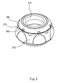
- Fig. 1 is an exploded diagram of one embodiment of the disclosure, depicting the bicycle handlebar lock device.
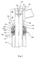
- Fig. 2 is a cutaway view of Fig. 1 .
- Fig. 3 is a part cutaway view of Fig. 1 , depicting the unlock status.
- Fig. 4 is a part cutaway view of Fig. 1 , depicting the lock status.
- the handlebar lock device includes a restrain cam set 200 and a cone-shape expanding set 300.
- the handlebar lock device is installed between an aheadset stem 100 and a head tube 110 of a bicycle.
- the bicycle has a set of pressing members 120.
- the pressing members 120 include a cover 121 mounted on the top of the aheadset stem 100, a leaf 122 arranged inside the aheadset stem 100, and a bolt 123 passed through the cover 121 and the leaf 122.
- the bolt 123 presses and connects the handlebar stem 130 to the bowl of the frame body, and thus to maintain the steadiness of the aheadset stem 100 when the aheadset stem 100 is coaxially rotated inside the head tube 110 of the frame body.
- the detail structure of the handlebar lock device is described as following:
- the restrain cam set 200 includes many ring shape members so that the aheadset stem 100 is passed through.
- the restrain cam set 200 is cooperated with the headset 210.
- the restrain cam set 200 includes a slide piece 240, an elasticity member 250 such as a spring, a supporting ring 260, a knob 270 and a shell 280.
- the headset 210 includes many balls 220 and a ball track 230.
- the headset 210 is fixed at the opening of the head tube110, and the head set 210 has a ball track 230 to position the balls 220.
- the first teeth 211 are located at the top of the headset 210.
- the ball track 230 has a third cone surface 231 located at the inner side of itself, and a packing ring 232 is arranged inside the third cone surface 231 to female joint the aheadset stem 100.
- the slide piece 240, the elasticity member 250, the supporting ring 260 and the knob 270 are positioned between the shell 280 and the headset 210.
- the top edge of the shell 280 has a second cone surface 281, and the lower lateral side of the shell 280 has a positioning part 282.
- the upper lateral edge of the shell 280 has several first marks 283.
- the upper inner edge of the slide piece 240 has a plate surface 241, the plate surface 241 is contacted and limited by the positioning part 282 of the shell 280, and thus can only be moved along the axial direction.
- the upper edge of the slide piece 240 has a cam surface 242 that forms a lumpy loop, and the cam surface 242 has several second slide parts 244.
- the down edge of the slide piece 240 has many second teeth 243 that correspond to the first teeth 211 of the headset 210.
- the top end of the elasticity member 250 presses the slide piece 240.
- the supporting ring 260 supports the lower edge of the slide piece 240, and being pressed by the bottom end of the elasticity member 250.
- the supporting ring 260 presses down the packing ring 232.
- the knob 270 is positioned and pivot mounted below the shell 280, and the knob 270 is rotatable.
- the knob 270 has lumpy shape cam part 271 that corresponds to the cam surface 242 of the slide piece 240.
- the knob 270 When the knob 270 is rotated, the first slide part 272 of the cam part 271 enables the slide piece 240 to move along the axial direction via the elastic force of the elasticity member 250. And then, the second teeth 243 located at the bottom edge of the slide piece 240 engages the first teeth 211 located at the headset 210, and thus the slide piece 240 connects the headset 210. Additionally, the outer surface of the knob 270 has some second marks 273 that correspond to the first marks 283 of the shell 280.
- the knob 270 is limited and pivot mounted below the shell 280, and the knob 270 can be shift rotated.
- the knob 270 has cam part 271 located at the inner side corresponding to the cam surface 242 of the slide piece 240.
- the cone-shape expanding set 300 includes a restrain ring 310 and several handlebar rings 320.
- the restrain ring 310 is located between the shell 280 and the aheadset stem 100, and the restrain ring 310 is limited and can only be moved between the headset stem 130 and the handlebar ring 320.
- the restrain ring 310 has a torsion spring opening 311 axially located at the surface of itself, and the first cone surface 312 located at the restrain ring 310 contacts and presses the second cone surface 281 located at the shell 280.
- the restrain ring 310 together with the friction force trigger the slide piece 240 to perform a slide wedge movement, and thus the torsion spring opening 311 is narrowed or widen thereby, and the aheadset stem 100 is also pressed or released by the restrain ring 310 thereby.
- One terminal of the handlebar ring 320 contacts and presses the handlebar stem 130, and the other terminal of the handlebar ring 320 contacts and presses the top end of the restrain ring 310. Therefore, the restrain ring 310 is pressed down by the handlebar ring 320, and thus generates a preset static friction force toward the aheadset stem 100.
- Fig. 5 is a schematic view of the bicycle handlebar lock device of Fig. 1 , depicting the unlock status.
- Fig. 6 is a schematic view of the bicycle handlebar lock device of Fig. 1 , depicting the lock status.
- the restrain cam set 200 of the bicycle handlebar lock device of the embodiment is pivot mounted on the head tube 110.
- the cone-shape expanding set 300 female joints the aheadset stem 100, and located between the restrain cam set 200 and the aheadset stem 100.
- the knob 270 of the restrain cam set 200 being limited and pivot mounted below the shell 280 is rotatable, and the rotation of the knob 270 makes the slide piece 240 to move axially via the first slide part 272 of the cam part 271 and the elastic force of the elasticity member 270.
- the second teeth 243 located at the bottom edge of the slide piece 240 are engaged with the first teeth 211 located at the top of the head set 210, and therefore the restrain cam set 200 connects the cone-shape expanding set 300, and thus the aheadset stem 100 is locked and positioned by the friction force of the restrain ring 310. As described above, the aheadset stem 100 is locked to prevent from fall down when it is parked.
- the first slide part 272 of the cam part 271 makes the slide piece 240 to move based on the elastic force of the elasticity member 250. Therefore, the second teeth 243 of the slide piece 240 are departed from the first teeth 211 of the headset 210, and thus the aheadset stem is unlocked.
- the restrain cam set 200 does not limit the cone-shape expanding set 300, and the cone-shape expanding set 300 can be rotated together with the aheadset stem 100. Therefore, the embodiment enables the user to operate the bicycle normally while the bicycle handlebar lock device is unlocked.
- the restrain ring 310 has a torsion spring opening 311 so that the cone-shape expanding set 300 can be extended by the slide edge movement.
- the slide edge movement is triggered by the rotate force and the friction force.
- the rotate force is provided though the aheadset stem 100 by the user, and the friction force is generated between the aheadset stem 100 and the cone-shape expanding set 300. Therefore, the aheadset stem 100 can be coaxially rotated inside the head tube 110 against the preset static friction force.
- the device of the embodiment prevents the user from falling down.
- a bicycle handlebar lock method is disclosed.
- the method is able to release the aheadset stem while a rotating force that larger than a preset static friction force is applied to rotate the aheadset stem.
- the method includes steps as following:
- the embodiment uses the slide wedge movement to generate the pressing force.
- the embodiment uses the engagement of the restrain cam set and the headset to lock the aheadset stem.
- the restrain cam set, the headset and the cone-shape expanding set enables the user to provide a rotating force to unlock the aheadset stem and thus prevent user from falling down.
- the disclosure includes at least the following advantages:
Landscapes
- Engineering & Computer Science (AREA)
- Mechanical Engineering (AREA)
- Steering Devices For Bicycles And Motorcycles (AREA)
Description
- The present disclosure relates to a bicycle steering device. More particular, the present disclosure relates to a bicycle handlebar lock device.
- Bicycle is an important transportation tool. The direction control of the bicycle is based on the design of the handlebar stem and the peripheral structure. In order to improve the direction control function of the bicycle, many efforts are invested in the design of the handlebar stem and the peripheral structure.
- Generally, the rear wheel of the bicycle is lined with the frame body, and the forward direction of the front wheel and the bicycle can be changed only by controlling the handlebar. In detail, the handlebar drives the aheadset stem and thus drives the front wheel installed on the aheadset stem. Furthermore, the driver keeps the balance of riding by shifting the handlebar to control the gravity center of his own body and the bicycle.
- When concerning the design of the bicycle, the handlebar connects the aheadset stem via a handlebar stem, wherein the handlebar stem is provided as a torque to drive the aheadset stem. A variety of handlebars are provided to satisfy different users.
- The aheadset stem is driven via the handlebar to control the forward direction of the front wheel, and thus to control the forward direction of the bicycle. The connecting interface between the head tube and the aheadset stem includes a hoop ring and a set of pressing members. The hoop ring female joints the handlebar stem to tie the aheadset stem, and the pressing members are applied to connect the frame body with the aheadset stem. The pressing members include a cover located at the top of the aheadset stem, a leaf located inside the aheadset stem, and a bolt pierces through and locked the cover with the leaf.
- The bolt presses and connects the handlebar stem to the bowl of the frame body, and thus to maintain the steadiness of the aheadset stem when the aheadset stem is coaxially rotated inside the head tube of the frame body. The design described above enables the handlebar stem to connect with the aheadset stem at a particular angle by operating the bolt and the hoop ring.
- However, when the bicycle is parked, the aheadset stem is swayed randomly due to its own weight. And it sometimes makes the bicycle to fall down. To solve the drawback described above, variety kinds of peripheral structure to lock or direct the aheadset stem are provided.
- Although the locking device that locks or directs the aheadset stem prevents the bicycle from fall down when parking, the users often forget to unlock the locking device before riding the bicycle, and thus get hurt when riding the bicycle without unlocking the locking device.
- Document
DE 949924 , which shows the features of the preamble ofclaim 1, relates to a steering damper for a motorcycle comprising spreading members passing through holes in a steering column which are configured to be pressed against a head tube for damping a relative rotation between the steering column and the head tube. - Starting from this state of the art it is the object of the present invention to provide a bicycle handlebar lock device which is easy to install and which does not lead to instability of the stem.
- This object is solved by the bicycle handlebar lock device according to
claim 1 and the bicycle handlebar lock method according to claim 14. Advantageous improvements of the present invention are described by the corresponding dependent claims. - One further aspect of the disclosure is to provide a bicycle handlebar lock device that is able to release the aheadset stem based on the user's riding behavior.
- According to one embodiment of the disclosure, the bicycle handlebar lock device is arranged between the aheadset stem and the head tube. The bicycle handlebar lock device includes a restrain cam set and a cone-shape expanding set. The restrain cam set is pivot installed at the head tube, and the cone-shape expanding set female joints the aheadset stem and is located between the restrain cam set and the aheadset stem.
- The cone-shape expanding set female joints the aheadset stem and thus provides a preset static friction force to the aheadset stem. The cam structure of the restrain cam set can be rotated and shifted to make the slide pieces of itself engage or depart with the headset. Therefore, the aheadset stem is restrained when the slide pieces is engaged with the headset, and the aheadset stem is released when the slide pieces is departed from the headset.
- Furthermore, the cone-shape expanding set enables the aheadset stem to release the aheadset stem while a rotating force larger than the preset static friction force is applied to rotate the aheadset stem.
- The restrain cam set is designed to be cooperated with the headset, the restrain cam set includes a slide piece, an elasticity member, a supporting ring, a knob and a shell.
- The shell is mounted on the top of the headset to make the slide piece, the elasticity member, the supporting ring and the knob to be positioned inside the headset. Wherein, the slide piece is restrained so that it can only be moved along the axial direction of the aheadset stem, and the knob is restrained so that it can only be rotated.
- The cam part is set inside the knob. The first slide part on the cam part enables the slide piece to be lifted by the pressing force of the elasticity member when the knob is rotated by the rotation of the aheadset stem.
- The slide piece of the restrain cam set can be moved along the axial direction of the aheadset stem against the pressing force of the elasticity member. And thus the second teeth located below the slide piece can be engaged with or departed from the first teeth located under the headset. Therefore, the cone-shape expanding set can be applied to lock the aheadset stem or release the aheadset stem.
- When the slide piece is engaged with the headset via their teeth, the aheadset stem is restrained by the restrain cam set and can not be rotated unless the applied force is larger than the preset static friction force of the cone-shape expanding set. Contrary, when the slide piece is departed from the headset, the rotation of the aheadset stem drives the restrain cam set to rotate together, and the balls inside the headset is applied to overcome the friction force of the cone-shape expanding set.
- The cone-shape expanding set includes a restrain ring, and the restrain ring has a first cone surface and a torsion spring opening located on the first cone surface. The shell has a second cone surface located at the inner side of itself, and the first cone surface touches the second cone surface.
- Therefore, the driving behavior of the user makes the user to press the restrain ring. The pressing force and the friction force of the restrain ring generate a slide wedge movement. The slide wedge movement makes the restrain ring contract, and the torsion spring opening is narrowed. Therefore, the restrain ring presses the aheadset stem tightly.
- Another aspect of the disclosure is to provide a bicycle handlebar lock method that is able to release the aheadset stem while a rotating force that larger than a preset static friction force is applied to rotate the aheadset stem, the method includes steps as following:
- First, arranging the bicycle handlebar lock device between the aheadset stem and the head tube, and pressing the aheadset stem by a preset static friction force.
- Second, applying a rotating force to the aheadset stem by the user.
- Third, releasing the aheadset stem by the applied rotating force, and thus enabling the aheadset stem to rotate relative to the head tube.
- In the steps described above, the disclosure uses the slide wedge movement to generate the pressing force, and using the engagement of the restrain cam set and the headset to lock the aheadset stem. The existence of the restrain cam set, the headset and the cone-shape expanding set enables the user to provide a rotating force to unlock the aheadset stem and thus prevent user from falling down.
- The invention can be more fully understood by reading the following detailed description of the embodiments, with reference made to the accompanying drawings as follows:
-
Fig. 1 is an exploded diagram of one embodiment of the disclosure, depicting the bicycle handlebar lock device. -
Fig. 2 is a cutaway view ofFig. 1 . -
Fig. 3 is a part cutaway view ofFig. 1 , depicting the unlock status. -
Fig. 4 is a part cutaway view ofFig. 1 , depicting the lock status. -
Fig. 5 is a schematic view of the bicycle handlebar lock device ofFig. 1 , depicting the unlock status. -
Fig. 6 is a schematic view of the bicycle handlebar lock device ofFig. 1 , depicting the lock status. - Refer to
Fig. 1 - 4 .Fig. 1 is an exploded diagram of one embodiment of the disclosure, depicting the bicycle handlebar lock device.Fig. 2 is a cutaway view ofFig. 1 .Fig. 3 is a part cutaway view ofFig. 1 , depicting the unlock status. AndFig. 4 is a part cutaway view ofFig. 1 , depicting the lock status. - The handlebar lock device includes a restrain
cam set 200 and a cone-shape expanding set 300. The handlebar lock device is installed between anaheadset stem 100 and ahead tube 110 of a bicycle. The bicycle has a set of pressingmembers 120. Thepressing members 120 include acover 121 mounted on the top of theaheadset stem 100, aleaf 122 arranged inside theaheadset stem 100, and abolt 123 passed through thecover 121 and theleaf 122. - The
bolt 123 presses and connects thehandlebar stem 130 to the bowl of the frame body, and thus to maintain the steadiness of the aheadset stem 100 when theaheadset stem 100 is coaxially rotated inside thehead tube 110 of the frame body. The detail structure of the handlebar lock device is described as following: - The restrain cam set 200 includes many ring shape members so that the aheadset stem 100 is passed through. The restrain cam set 200 is cooperated with the
headset 210. In detail, the restrain cam set 200 includes aslide piece 240, anelasticity member 250 such as a spring, a supportingring 260, aknob 270 and ashell 280. - The
headset 210 includesmany balls 220 and aball track 230. Theheadset 210 is fixed at the opening of the head tube110, and the head set 210 has aball track 230 to position theballs 220. Thefirst teeth 211 are located at the top of theheadset 210. Theball track 230 has athird cone surface 231 located at the inner side of itself, and apacking ring 232 is arranged inside thethird cone surface 231 to female joint theaheadset stem 100. - The
slide piece 240, theelasticity member 250, the supportingring 260 and theknob 270 are positioned between theshell 280 and theheadset 210. The top edge of theshell 280 has asecond cone surface 281, and the lower lateral side of theshell 280 has apositioning part 282. The upper lateral edge of theshell 280 has severalfirst marks 283. - The upper inner edge of the
slide piece 240 has aplate surface 241, theplate surface 241 is contacted and limited by thepositioning part 282 of theshell 280, and thus can only be moved along the axial direction. The upper edge of theslide piece 240 has acam surface 242 that forms a lumpy loop, and thecam surface 242 has severalsecond slide parts 244. The down edge of theslide piece 240 has manysecond teeth 243 that correspond to thefirst teeth 211 of theheadset 210. - The top end of the
elasticity member 250 presses theslide piece 240. The supportingring 260 supports the lower edge of theslide piece 240, and being pressed by the bottom end of theelasticity member 250. The supportingring 260 presses down thepacking ring 232. - The
knob 270 is positioned and pivot mounted below theshell 280, and theknob 270 is rotatable. Theknob 270 has lumpyshape cam part 271 that corresponds to thecam surface 242 of theslide piece 240. - When the
knob 270 is rotated, thefirst slide part 272 of thecam part 271 enables theslide piece 240 to move along the axial direction via the elastic force of theelasticity member 250. And then, thesecond teeth 243 located at the bottom edge of theslide piece 240 engages thefirst teeth 211 located at theheadset 210, and thus theslide piece 240 connects theheadset 210. Additionally, the outer surface of theknob 270 has somesecond marks 273 that correspond to thefirst marks 283 of theshell 280. - The
knob 270 is limited and pivot mounted below theshell 280, and theknob 270 can be shift rotated. Theknob 270 hascam part 271 located at the inner side corresponding to thecam surface 242 of theslide piece 240. - The cone-shape expanding set 300 includes a restrain
ring 310 and several handlebar rings 320. The restrainring 310 is located between theshell 280 and theaheadset stem 100, and the restrainring 310 is limited and can only be moved between theheadset stem 130 and thehandlebar ring 320. - The restrain
ring 310 has atorsion spring opening 311 axially located at the surface of itself, and thefirst cone surface 312 located at the restrainring 310 contacts and presses thesecond cone surface 281 located at theshell 280. The restrainring 310 together with the friction force trigger theslide piece 240 to perform a slide wedge movement, and thus thetorsion spring opening 311 is narrowed or widen thereby, and the aheadset stem 100 is also pressed or released by the restrainring 310 thereby. - One terminal of the
handlebar ring 320 contacts and presses thehandlebar stem 130, and the other terminal of thehandlebar ring 320 contacts and presses the top end of the restrainring 310. Therefore, the restrainring 310 is pressed down by thehandlebar ring 320, and thus generates a preset static friction force toward theaheadset stem 100. - Refer to
Fig. 5 andFig. 6 .Fig. 5 is a schematic view of the bicycle handlebar lock device ofFig. 1 , depicting the unlock status.Fig. 6 is a schematic view of the bicycle handlebar lock device ofFig. 1 , depicting the lock status. - The restrain cam set 200 of the bicycle handlebar lock device of the embodiment is pivot mounted on the
head tube 110. The cone-shape expanding set 300 female joints the aheadset stem 100, and located between the restraincam set 200 and theaheadset stem 100. - The
knob 270 of the restrain cam set 200 being limited and pivot mounted below theshell 280 is rotatable, and the rotation of theknob 270 makes theslide piece 240 to move axially via thefirst slide part 272 of thecam part 271 and the elastic force of theelasticity member 270. - In detail, the
second teeth 243 located at the bottom edge of theslide piece 240 are engaged with thefirst teeth 211 located at the top of the head set 210, and therefore the restrain cam set 200 connects the cone-shape expanding set 300, and thus the aheadset stem 100 is locked and positioned by the friction force of the restrainring 310. As described above, the aheadset stem 100 is locked to prevent from fall down when it is parked. - Similarly, once the user rotates the
knob 270, thefirst slide part 272 of thecam part 271 makes theslide piece 240 to move based on the elastic force of theelasticity member 250. Therefore, thesecond teeth 243 of theslide piece 240 are departed from thefirst teeth 211 of theheadset 210, and thus the aheadset stem is unlocked. - Meanwhile, although the restrain
ring 310 still provides friction force to theaheadset stem 100, the restrain cam set 200 does not limit the cone-shape expanding set 300, and the cone-shape expanding set 300 can be rotated together with theaheadset stem 100. Therefore, the embodiment enables the user to operate the bicycle normally while the bicycle handlebar lock device is unlocked. - Furthermore, the restrain
ring 310 has atorsion spring opening 311 so that the cone-shape expanding set 300 can be extended by the slide edge movement. Wherein, the slide edge movement is triggered by the rotate force and the friction force. The rotate force is provided though the aheadset stem 100 by the user, and the friction force is generated between theaheadset stem 100 and the cone-shape expanding set 300. Therefore, the aheadset stem 100 can be coaxially rotated inside thehead tube 110 against the preset static friction force. - Therefore, if the user forgets to rotate the
knob 270 to unlock the device after it has been locked, and the restrainring 310 of the cone-shape expanding set 300 still restrains theaheadset stem 100, the user can still provide a torque force to the aheadset stem 100 to make it coaxially rotate inside thehead tube 110 against the preset static friction force. Therefore, the device of the embodiment prevents the user from falling down. - According to another embodiment of the disclosure, a bicycle handlebar lock method is disclosed. The method is able to release the aheadset stem while a rotating force that larger than a preset static friction force is applied to rotate the aheadset stem. The method includes steps as following:
- First, arranging the bicycle handlebar lock device between the aheadset stem and the head tube, and pressing the aheadset stem by a preset static friction force. Second, applying a rotating force to the aheadset stem. Third, releasing the aheadset stem by the applied rotating force, and thus enabling the aheadset stem to rotate relative to the head tube.
- In the steps described above, the embodiment uses the slide wedge movement to generate the pressing force. The embodiment uses the engagement of the restrain cam set and the headset to lock the aheadset stem. The restrain cam set, the headset and the cone-shape expanding set enables the user to provide a rotating force to unlock the aheadset stem and thus prevent user from falling down.
- As described above, the disclosure includes at least the following advantages:
- First, the bicycle handlebar lock device and method locks the aheadset stem and thus prevents the bicycle from falling down while being parked.
- Second, the bicycle handlebar lock device and method prevents the user from falling down even if the user forgets to unlock the device.
Claims (15)
- A bicycle handlebar lock device comprising:a cone-shaped expanding set (300);a restrain cam set (200); anda headset (210) mounted at a head tube (110) for supporting the cone-shape expanding set (300) and the restrain cam set (200);wherein, the restrain cam set (200) is rotatable to engage the headset for locking the aheadset stem by a preset static friction force,characterized in that the cone-shape expanding set (300) is configured to surround an aheadset stem (100) and the restrain cam set (200) is configured to surround the cone-shape expanding set (300) and to contract the cone-shape expanding set (300) for locking the aheadset stem (100) by the preset static friction force by rotating the restrain cam set (200).
- The bicycle handlebar lock device of claim 1, characterized by further comprising a plurality of balls (220) and a ball track (230) embedded in the headset (210).
- The bicycle handlebar lock device of claim 1, characterized in that wherein the restrain cam set (200) comprises:a slide piece (240) being movable along the axial direction of the head tube (110), the slide piece (240) having a first cam set;an elasticity member (250) being applied to uplift the slide piece (240);a supporting ring (260) being applied to support the elasticity member (250);a knob (270) being rotate and surrounding the head tube (110) and covering the slide piece (240), the knob (270) having a second cam set corresponding to the first cam set; anda shell (280) mounted on the knob (270).
- The bicycle handlebar lock device of claim 3, characterized in that wherein the elasticity member (250) is a spring.
- The bicycle handlebar lock device of claim 3, characterized in that wherein the cone-shape expanding set (300) further comprises a restrain ring (310) located between the upper shell and the aheadset stem (100) for locking the aheadset stem (100).
- The bicycle handlebar lock device of claim 5, characterized in that wherein the restrain ring (310) further comprises:a torsion spring opening (311); anda first cone surface (312) for contacting and supporting a second cone surface (281) of the shell (280).
- The bicycle handlebar lock device of claim 5, characterized by further comprising:at least one handlebar ring (320), one side of the handlebar ring (320) contacting the handlebar stem (130), and the other side of the handlebar ring (320) contacting the restrain ring (310).
- The bicycle handlebar lock device of claim 3, characterized in that wherein the shell (280) has several first marks, and the knob (270) has several second marks corresponding to the first marks.
- A bicycle handlebar lock device of claim 1, which is installed between the aheadset stem (100) and the head tube (110), characterized in that:the cone-shape expanding set (300) joints the aheadset stem (100);the headset (210) is static installed at the top of the head tube (110), the headset (210) having a lower teeth; andthe restrain cam set (200) is located between the cone-shape expanding set (300) and the headset (210), the restrain cam set (200) having an upper teeth corresponding to the lower teeth, and the restrain cam set (200) partly covering the cone-shape expanding set (300);wherein, the restrain cam set (200) can be rotated to engage the headset (210) via the upper teeth and the lower teeth, and therefore to press the cone-shape expanding set (300) to lock the aheadset stem (100) by a preset static friction force, the restrain cam set (200) also can be rotated to depart the upper teeth from the lower teeth, and therefore to eliminate the preset static friction force to unlock the aheadset stem (100).
- The bicycle handlebar lock device of claim 9, characterized in that
wherein
the headset (210) further comprises a plurality of balls (220) and a ball track (230); and
the restrain cam set (200) further comprises a slide piece (240), a elasticity member (250), a supporting ring (260), a knob (270) and a shell (280);
wherein the slide piece (240), the elasticity member (250), the supporting ring (260) and the knob (270) are embedded between the headset (210) and the shell (280), the slide piece is movable along the axial direction of the head tube, the knob (270) can be rotated, two sets of cam parts are alternatively located on the knob (270) and the slide piece (240) correspondingly, the rotating level shift between the knob and the slide piece (240) via the slide parts of the cam parts makes the slide piece (240) to move along the axial direction of the head tube (110) by using the elastic force of the elasticity member (250), and the upper teeth are arranged under the slide piece (240). - The bicycle handlebar lock device of claim 10, characterized in that wherein the cone-shape expanding set (300) further comprises a restrain ring (310), the restrain ring (310) is located between the upper shell and the aheadset stem (100), the restrain ring (310) has a torsion spring opening (311), and the restrain ring (310) has one cone surface to contact and support another cone surface of the shell (280), these two cone surfaces are contacted to each other, and can be driven to move relatively to push the restrain ring (310) to lock the aheadset stem (100).
- The bicycle handlebar lock device of claim 11, characterized by further comprising:at least one handlebar ring (320), one side of the handlebar ring (320) contacting the handlebar stem (130), and the other side of the handlebar ring (320) contacting the restrain ring (310), the restrain ring (310) being able to lock the aheadset stem (100) by the preset static friction force when the restrain ring (310) is pressed down via the handlebar ring (320).
- The bicycle handlebar lock device of claim 10, characterized in that wherein the elasticity member (250) is a spring.
- A bicycle handlebar lock method comprising:installing a bicycle handlebar lock device according to one of the preceding claims between an aheadset stem (100) and a head tube (110), and locking the aheadset stem (100) by a preset static fraction force;applying a torque force to the aheadset stem (100); andusing the torque force to overcome the preset static fraction force, and therefore unlocking the aheadset stem (100).
- The bicycle handlebar lock method of claim 14, characterized by further comprising:locking the aheadset stem (100) by the preset static fraction force via the restrain cam set (200) and the cone-shape expanding set (300) of the bicycle handlebar lock device;applying the torque force to the aheadset stem (100) via the handlebar stem (130); andusing the torque force to overcome the preset static fraction force, and further releasing the cone-shape expanding set (300) to eliminate the preset static fraction force.
Applications Claiming Priority (1)
| Application Number | Priority Date | Filing Date | Title |
|---|---|---|---|
| TW098111553A TWI368588B (en) | 2009-04-07 | 2009-04-07 | A method and a handlebar lock structure for a bicycle |
Publications (3)
| Publication Number | Publication Date |
|---|---|
| EP2239189A2 EP2239189A2 (en) | 2010-10-13 |
| EP2239189A3 EP2239189A3 (en) | 2011-04-27 |
| EP2239189B1 true EP2239189B1 (en) | 2012-09-26 |
Family
ID=42238628
Family Applications (1)
| Application Number | Title | Priority Date | Filing Date |
|---|---|---|---|
| EP20090177581 Active EP2239189B1 (en) | 2009-04-07 | 2009-12-01 | Bicycle handlebar lock device and method of the same |
Country Status (2)
| Country | Link |
|---|---|
| EP (1) | EP2239189B1 (en) |
| TW (1) | TWI368588B (en) |
Families Citing this family (4)
| Publication number | Priority date | Publication date | Assignee | Title |
|---|---|---|---|---|
| CN106828677A (en) * | 2017-03-16 | 2017-06-13 | 宁波巨隆机械股份有限公司 | The steering lock of handle-bar direction positioning can be realized |
| CN112660286A (en) * | 2020-12-31 | 2021-04-16 | 句容志新精密五金零件有限公司 | Integrated bicycle head bowl group based on carbon fiber reinforcement |
| TWI885702B (en) * | 2024-01-16 | 2025-06-01 | 誌慶工業股份有限公司 | Front bowl group of restricted steering |
| TWI913656B (en) | 2024-02-15 | 2026-02-01 | 金盛元興業股份有限公司 | A bike stopping component |
Family Cites Families (3)
| Publication number | Priority date | Publication date | Assignee | Title |
|---|---|---|---|---|
| GB270808A (en) * | 1926-02-13 | 1927-05-13 | William Holder Osborne | An improved frictional damping device for the steering mechanism of motor cycles and the like |
| FR968488A (en) * | 1948-06-29 | 1950-11-28 | Verot Perrin Ets | Steering of bicycles, tandems or the like with spherical bearings |
| DE949924C (en) * | 1951-08-05 | 1956-09-27 | Motorrad Und Fahrradteilefabri | Adjustable steering damper for motorcycles |
-
2009
- 2009-04-07 TW TW098111553A patent/TWI368588B/en active
- 2009-12-01 EP EP20090177581 patent/EP2239189B1/en active Active
Also Published As
| Publication number | Publication date |
|---|---|
| EP2239189A2 (en) | 2010-10-13 |
| TWI368588B (en) | 2012-07-21 |
| EP2239189A3 (en) | 2011-04-27 |
| TW201036863A (en) | 2010-10-16 |
Similar Documents
| Publication | Publication Date | Title |
|---|---|---|
| US8037782B2 (en) | Steering column assembly | |
| EP3666624B1 (en) | Steering column device | |
| EP2239189A2 (en) | Bicycle handlebar lock device and method of the same | |
| JP2006076510A (en) | Bicycle head component | |
| JP2005247296A5 (en) | ||
| JPH111189A (en) | Bicycle with anti-theft device | |
| CN111971223B (en) | Multifunctional foldable handlebar for bicycle (or general wheel-rotating vehicle) | |
| JP5222692B2 (en) | Steering column device | |
| US7625002B2 (en) | Vehicle frame with a rotation limiting mechanism for limiting rotation of a steerer relative to a head tube | |
| TW200524776A (en) | Suspension adjustment actuator apparatus | |
| TWI460095B (en) | Can limit the steering angle of the front bowl assembly | |
| WO2009045260A1 (en) | Quick release stem | |
| US7377526B2 (en) | Wheel-mounting assembly for a stroller | |
| JP2012076736A (en) | Wheel retaining device for bicycle carrier | |
| US8376404B2 (en) | Integrated tooth rake lock for steering column | |
| TWM528275U (en) | Locking device for steering head of car | |
| JP6183833B2 (en) | Bicycle handle lock device | |
| JP2008006840A (en) | Steering column device | |
| CN103507898B (en) | A kind of system for being used to be fastened to accessory on bicycle | |
| JP4248340B2 (en) | Motorcycle | |
| CN101857061B (en) | Bicycle steering safety slipping device and method thereof | |
| JPS6215396B2 (en) | ||
| US8152190B2 (en) | Quick release stem | |
| JP7546495B2 (en) | Stand Device | |
| EP2839992B1 (en) | Carrier apparatus |
Legal Events
| Date | Code | Title | Description |
|---|---|---|---|
| PUAI | Public reference made under article 153(3) epc to a published international application that has entered the european phase |
Free format text: ORIGINAL CODE: 0009012 |
|
| 17P | Request for examination filed |
Effective date: 20091230 |
|
| AK | Designated contracting states |
Kind code of ref document: A2 Designated state(s): AT BE BG CH CY CZ DE DK EE ES FI FR GB GR HR HU IE IS IT LI LT LU LV MC MK MT NL NO PL PT RO SE SI SK SM TR |
|
| AX | Request for extension of the european patent |
Extension state: AL BA RS |
|
| PUAL | Search report despatched |
Free format text: ORIGINAL CODE: 0009013 |
|
| AK | Designated contracting states |
Kind code of ref document: A3 Designated state(s): AT BE BG CH CY CZ DE DK EE ES FI FR GB GR HR HU IE IS IT LI LT LU LV MC MK MT NL NO PL PT RO SE SI SK SM TR |
|
| AX | Request for extension of the european patent |
Extension state: AL BA RS |
|
| RIC1 | Information provided on ipc code assigned before grant |
Ipc: B62H 5/06 20060101ALI20110318BHEP Ipc: B62K 21/06 20060101AFI20100618BHEP Ipc: B62K 21/08 20060101ALI20110318BHEP |
|
| GRAP | Despatch of communication of intention to grant a patent |
Free format text: ORIGINAL CODE: EPIDOSNIGR1 |
|
| GRAS | Grant fee paid |
Free format text: ORIGINAL CODE: EPIDOSNIGR3 |
|
| GRAA | (expected) grant |
Free format text: ORIGINAL CODE: 0009210 |
|
| AK | Designated contracting states |
Kind code of ref document: B1 Designated state(s): AT BE BG CH CY CZ DE DK EE ES FI FR GB GR HR HU IE IS IT LI LT LU LV MC MK MT NL NO PL PT RO SE SI SK SM TR |
|
| REG | Reference to a national code |
Ref country code: GB Ref legal event code: FG4D |
|
| REG | Reference to a national code |
Ref country code: CH Ref legal event code: EP |
|
| REG | Reference to a national code |
Ref country code: AT Ref legal event code: REF Ref document number: 576900 Country of ref document: AT Kind code of ref document: T Effective date: 20121015 |
|
| REG | Reference to a national code |
Ref country code: IE Ref legal event code: FG4D |
|
| REG | Reference to a national code |
Ref country code: NL Ref legal event code: T3 |
|
| REG | Reference to a national code |
Ref country code: DE Ref legal event code: R096 Ref document number: 602009009977 Country of ref document: DE Effective date: 20121122 |
|
| PG25 | Lapsed in a contracting state [announced via postgrant information from national office to epo] |
Ref country code: NO Free format text: LAPSE BECAUSE OF FAILURE TO SUBMIT A TRANSLATION OF THE DESCRIPTION OR TO PAY THE FEE WITHIN THE PRESCRIBED TIME-LIMIT Effective date: 20121226 Ref country code: FI Free format text: LAPSE BECAUSE OF FAILURE TO SUBMIT A TRANSLATION OF THE DESCRIPTION OR TO PAY THE FEE WITHIN THE PRESCRIBED TIME-LIMIT Effective date: 20120926 Ref country code: HR Free format text: LAPSE BECAUSE OF FAILURE TO SUBMIT A TRANSLATION OF THE DESCRIPTION OR TO PAY THE FEE WITHIN THE PRESCRIBED TIME-LIMIT Effective date: 20120926 Ref country code: LT Free format text: LAPSE BECAUSE OF FAILURE TO SUBMIT A TRANSLATION OF THE DESCRIPTION OR TO PAY THE FEE WITHIN THE PRESCRIBED TIME-LIMIT Effective date: 20120926 |
|
| REG | Reference to a national code |
Ref country code: AT Ref legal event code: MK05 Ref document number: 576900 Country of ref document: AT Kind code of ref document: T Effective date: 20120926 |
|
| REG | Reference to a national code |
Ref country code: LT Ref legal event code: MG4D Effective date: 20120926 |
|
| PG25 | Lapsed in a contracting state [announced via postgrant information from national office to epo] |
Ref country code: LV Free format text: LAPSE BECAUSE OF FAILURE TO SUBMIT A TRANSLATION OF THE DESCRIPTION OR TO PAY THE FEE WITHIN THE PRESCRIBED TIME-LIMIT Effective date: 20120926 Ref country code: SI Free format text: LAPSE BECAUSE OF FAILURE TO SUBMIT A TRANSLATION OF THE DESCRIPTION OR TO PAY THE FEE WITHIN THE PRESCRIBED TIME-LIMIT Effective date: 20120926 Ref country code: GR Free format text: LAPSE BECAUSE OF FAILURE TO SUBMIT A TRANSLATION OF THE DESCRIPTION OR TO PAY THE FEE WITHIN THE PRESCRIBED TIME-LIMIT Effective date: 20121227 Ref country code: SE Free format text: LAPSE BECAUSE OF FAILURE TO SUBMIT A TRANSLATION OF THE DESCRIPTION OR TO PAY THE FEE WITHIN THE PRESCRIBED TIME-LIMIT Effective date: 20120926 |
|
| PG25 | Lapsed in a contracting state [announced via postgrant information from national office to epo] |
Ref country code: ES Free format text: LAPSE BECAUSE OF FAILURE TO SUBMIT A TRANSLATION OF THE DESCRIPTION OR TO PAY THE FEE WITHIN THE PRESCRIBED TIME-LIMIT Effective date: 20130106 Ref country code: BE Free format text: LAPSE BECAUSE OF FAILURE TO SUBMIT A TRANSLATION OF THE DESCRIPTION OR TO PAY THE FEE WITHIN THE PRESCRIBED TIME-LIMIT Effective date: 20120926 Ref country code: IS Free format text: LAPSE BECAUSE OF FAILURE TO SUBMIT A TRANSLATION OF THE DESCRIPTION OR TO PAY THE FEE WITHIN THE PRESCRIBED TIME-LIMIT Effective date: 20130126 Ref country code: CZ Free format text: LAPSE BECAUSE OF FAILURE TO SUBMIT A TRANSLATION OF THE DESCRIPTION OR TO PAY THE FEE WITHIN THE PRESCRIBED TIME-LIMIT Effective date: 20120926 Ref country code: RO Free format text: LAPSE BECAUSE OF FAILURE TO SUBMIT A TRANSLATION OF THE DESCRIPTION OR TO PAY THE FEE WITHIN THE PRESCRIBED TIME-LIMIT Effective date: 20120926 Ref country code: EE Free format text: LAPSE BECAUSE OF FAILURE TO SUBMIT A TRANSLATION OF THE DESCRIPTION OR TO PAY THE FEE WITHIN THE PRESCRIBED TIME-LIMIT Effective date: 20120926 |
|
| REG | Reference to a national code |
Ref country code: DE Ref legal event code: R082 Ref document number: 602009009977 Country of ref document: DE Representative=s name: LANGPATENT ANWALTSKANZLEI IP LAW FIRM, DE Ref country code: DE Ref legal event code: R082 Ref document number: 602009009977 Country of ref document: DE Representative=s name: LANGPATENT ANWALTSKANZLEI, DE |
|
| PG25 | Lapsed in a contracting state [announced via postgrant information from national office to epo] |
Ref country code: PL Free format text: LAPSE BECAUSE OF FAILURE TO SUBMIT A TRANSLATION OF THE DESCRIPTION OR TO PAY THE FEE WITHIN THE PRESCRIBED TIME-LIMIT Effective date: 20120926 Ref country code: PT Free format text: LAPSE BECAUSE OF FAILURE TO SUBMIT A TRANSLATION OF THE DESCRIPTION OR TO PAY THE FEE WITHIN THE PRESCRIBED TIME-LIMIT Effective date: 20130128 Ref country code: SK Free format text: LAPSE BECAUSE OF FAILURE TO SUBMIT A TRANSLATION OF THE DESCRIPTION OR TO PAY THE FEE WITHIN THE PRESCRIBED TIME-LIMIT Effective date: 20120926 |
|
| PG25 | Lapsed in a contracting state [announced via postgrant information from national office to epo] |
Ref country code: AT Free format text: LAPSE BECAUSE OF FAILURE TO SUBMIT A TRANSLATION OF THE DESCRIPTION OR TO PAY THE FEE WITHIN THE PRESCRIBED TIME-LIMIT Effective date: 20120926 |
|
| PG25 | Lapsed in a contracting state [announced via postgrant information from national office to epo] |
Ref country code: MC Free format text: LAPSE BECAUSE OF NON-PAYMENT OF DUE FEES Effective date: 20121231 Ref country code: DK Free format text: LAPSE BECAUSE OF FAILURE TO SUBMIT A TRANSLATION OF THE DESCRIPTION OR TO PAY THE FEE WITHIN THE PRESCRIBED TIME-LIMIT Effective date: 20120926 Ref country code: BG Free format text: LAPSE BECAUSE OF FAILURE TO SUBMIT A TRANSLATION OF THE DESCRIPTION OR TO PAY THE FEE WITHIN THE PRESCRIBED TIME-LIMIT Effective date: 20121226 |
|
| PLBE | No opposition filed within time limit |
Free format text: ORIGINAL CODE: 0009261 |
|
| STAA | Information on the status of an ep patent application or granted ep patent |
Free format text: STATUS: NO OPPOSITION FILED WITHIN TIME LIMIT |
|
| PG25 | Lapsed in a contracting state [announced via postgrant information from national office to epo] |
Ref country code: IT Free format text: LAPSE BECAUSE OF FAILURE TO SUBMIT A TRANSLATION OF THE DESCRIPTION OR TO PAY THE FEE WITHIN THE PRESCRIBED TIME-LIMIT Effective date: 20120926 |
|
| 26N | No opposition filed |
Effective date: 20130627 |
|
| REG | Reference to a national code |
Ref country code: IE Ref legal event code: MM4A |
|
| REG | Reference to a national code |
Ref country code: DE Ref legal event code: R097 Ref document number: 602009009977 Country of ref document: DE Effective date: 20130627 |
|
| PG25 | Lapsed in a contracting state [announced via postgrant information from national office to epo] |
Ref country code: IE Free format text: LAPSE BECAUSE OF NON-PAYMENT OF DUE FEES Effective date: 20121201 |
|
| PG25 | Lapsed in a contracting state [announced via postgrant information from national office to epo] |
Ref country code: CY Free format text: LAPSE BECAUSE OF FAILURE TO SUBMIT A TRANSLATION OF THE DESCRIPTION OR TO PAY THE FEE WITHIN THE PRESCRIBED TIME-LIMIT Effective date: 20120926 Ref country code: MT Free format text: LAPSE BECAUSE OF FAILURE TO SUBMIT A TRANSLATION OF THE DESCRIPTION OR TO PAY THE FEE WITHIN THE PRESCRIBED TIME-LIMIT Effective date: 20120926 |
|
| PG25 | Lapsed in a contracting state [announced via postgrant information from national office to epo] |
Ref country code: TR Free format text: LAPSE BECAUSE OF FAILURE TO SUBMIT A TRANSLATION OF THE DESCRIPTION OR TO PAY THE FEE WITHIN THE PRESCRIBED TIME-LIMIT Effective date: 20120926 |
|
| PG25 | Lapsed in a contracting state [announced via postgrant information from national office to epo] |
Ref country code: SM Free format text: LAPSE BECAUSE OF FAILURE TO SUBMIT A TRANSLATION OF THE DESCRIPTION OR TO PAY THE FEE WITHIN THE PRESCRIBED TIME-LIMIT Effective date: 20120926 Ref country code: LU Free format text: LAPSE BECAUSE OF NON-PAYMENT OF DUE FEES Effective date: 20121201 |
|
| PG25 | Lapsed in a contracting state [announced via postgrant information from national office to epo] |
Ref country code: HU Free format text: LAPSE BECAUSE OF FAILURE TO SUBMIT A TRANSLATION OF THE DESCRIPTION OR TO PAY THE FEE WITHIN THE PRESCRIBED TIME-LIMIT Effective date: 20091201 |
|
| REG | Reference to a national code |
Ref country code: CH Ref legal event code: PL |
|
| GBPC | Gb: european patent ceased through non-payment of renewal fee |
Effective date: 20131201 |
|
| PG25 | Lapsed in a contracting state [announced via postgrant information from national office to epo] |
Ref country code: CH Free format text: LAPSE BECAUSE OF NON-PAYMENT OF DUE FEES Effective date: 20131231 Ref country code: LI Free format text: LAPSE BECAUSE OF NON-PAYMENT OF DUE FEES Effective date: 20131231 |
|
| PG25 | Lapsed in a contracting state [announced via postgrant information from national office to epo] |
Ref country code: GB Free format text: LAPSE BECAUSE OF NON-PAYMENT OF DUE FEES Effective date: 20131201 |
|
| PG25 | Lapsed in a contracting state [announced via postgrant information from national office to epo] |
Ref country code: MK Free format text: LAPSE BECAUSE OF FAILURE TO SUBMIT A TRANSLATION OF THE DESCRIPTION OR TO PAY THE FEE WITHIN THE PRESCRIBED TIME-LIMIT Effective date: 20120926 |
|
| REG | Reference to a national code |
Ref country code: FR Ref legal event code: PLFP Year of fee payment: 7 |
|
| REG | Reference to a national code |
Ref country code: FR Ref legal event code: PLFP Year of fee payment: 8 |
|
| REG | Reference to a national code |
Ref country code: FR Ref legal event code: PLFP Year of fee payment: 9 |
|
| PGFP | Annual fee paid to national office [announced via postgrant information from national office to epo] |
Ref country code: NL Payment date: 20251120 Year of fee payment: 17 |
|
| PGFP | Annual fee paid to national office [announced via postgrant information from national office to epo] |
Ref country code: DE Payment date: 20251125 Year of fee payment: 17 |
|
| PGFP | Annual fee paid to national office [announced via postgrant information from national office to epo] |
Ref country code: FR Payment date: 20251201 Year of fee payment: 17 |