EP2239129A1 - Center mechanism of tire vulcanizing machine - Google Patents
Center mechanism of tire vulcanizing machine Download PDFInfo
- Publication number
- EP2239129A1 EP2239129A1 EP09170220A EP09170220A EP2239129A1 EP 2239129 A1 EP2239129 A1 EP 2239129A1 EP 09170220 A EP09170220 A EP 09170220A EP 09170220 A EP09170220 A EP 09170220A EP 2239129 A1 EP2239129 A1 EP 2239129A1
- Authority
- EP
- European Patent Office
- Prior art keywords
- hub
- spacer
- clamp ring
- heating
- bladder
- Prior art date
- Legal status (The legal status is an assumption and is not a legal conclusion. Google has not performed a legal analysis and makes no representation as to the accuracy of the status listed.)
- Granted
Links
Images



Classifications
-
- B—PERFORMING OPERATIONS; TRANSPORTING
- B29—WORKING OF PLASTICS; WORKING OF SUBSTANCES IN A PLASTIC STATE IN GENERAL
- B29D—PRODUCING PARTICULAR ARTICLES FROM PLASTICS OR FROM SUBSTANCES IN A PLASTIC STATE
- B29D30/00—Producing pneumatic or solid tyres or parts thereof
- B29D30/06—Pneumatic tyres or parts thereof (e.g. produced by casting, moulding, compression moulding, injection moulding, centrifugal casting)
- B29D30/0601—Vulcanising tyres; Vulcanising presses for tyres
- B29D30/0645—Devices for inserting vulcanising cores, i.e. bladders, into the tyres; Closing the press in combination herewith
-
- B—PERFORMING OPERATIONS; TRANSPORTING
- B29—WORKING OF PLASTICS; WORKING OF SUBSTANCES IN A PLASTIC STATE IN GENERAL
- B29C—SHAPING OR JOINING OF PLASTICS; SHAPING OF MATERIAL IN A PLASTIC STATE, NOT OTHERWISE PROVIDED FOR; AFTER-TREATMENT OF THE SHAPED PRODUCTS, e.g. REPAIRING
- B29C35/00—Heating, cooling or curing, e.g. crosslinking or vulcanising; Apparatus therefor
- B29C35/02—Heating or curing, e.g. crosslinking or vulcanizing during moulding, e.g. in a mould
-
- B—PERFORMING OPERATIONS; TRANSPORTING
- B29—WORKING OF PLASTICS; WORKING OF SUBSTANCES IN A PLASTIC STATE IN GENERAL
- B29C—SHAPING OR JOINING OF PLASTICS; SHAPING OF MATERIAL IN A PLASTIC STATE, NOT OTHERWISE PROVIDED FOR; AFTER-TREATMENT OF THE SHAPED PRODUCTS, e.g. REPAIRING
- B29C33/00—Moulds or cores; Details thereof or accessories therefor
- B29C33/20—Opening, closing or clamping
-
- B—PERFORMING OPERATIONS; TRANSPORTING
- B29—WORKING OF PLASTICS; WORKING OF SUBSTANCES IN A PLASTIC STATE IN GENERAL
- B29C—SHAPING OR JOINING OF PLASTICS; SHAPING OF MATERIAL IN A PLASTIC STATE, NOT OTHERWISE PROVIDED FOR; AFTER-TREATMENT OF THE SHAPED PRODUCTS, e.g. REPAIRING
- B29C33/00—Moulds or cores; Details thereof or accessories therefor
- B29C33/30—Mounting, exchanging or centering
- B29C33/303—Mounting, exchanging or centering centering mould parts or halves, e.g. during mounting
- B29C33/304—Mounting, exchanging or centering centering mould parts or halves, e.g. during mounting centering cores
-
- B—PERFORMING OPERATIONS; TRANSPORTING
- B29—WORKING OF PLASTICS; WORKING OF SUBSTANCES IN A PLASTIC STATE IN GENERAL
- B29D—PRODUCING PARTICULAR ARTICLES FROM PLASTICS OR FROM SUBSTANCES IN A PLASTIC STATE
- B29D30/00—Producing pneumatic or solid tyres or parts thereof
- B29D30/06—Pneumatic tyres or parts thereof (e.g. produced by casting, moulding, compression moulding, injection moulding, centrifugal casting)
- B29D30/08—Building tyres
-
- B—PERFORMING OPERATIONS; TRANSPORTING
- B29—WORKING OF PLASTICS; WORKING OF SUBSTANCES IN A PLASTIC STATE IN GENERAL
- B29D—PRODUCING PARTICULAR ARTICLES FROM PLASTICS OR FROM SUBSTANCES IN A PLASTIC STATE
- B29D30/00—Producing pneumatic or solid tyres or parts thereof
- B29D30/06—Pneumatic tyres or parts thereof (e.g. produced by casting, moulding, compression moulding, injection moulding, centrifugal casting)
- B29D30/0601—Vulcanising tyres; Vulcanising presses for tyres
- B29D30/0645—Devices for inserting vulcanising cores, i.e. bladders, into the tyres; Closing the press in combination herewith
- B29D2030/0646—Attaching to, or removing the vulcanizing cores or bladders from the center mechanisms
Definitions
- This invention relates to a center mechanism of a tire vulcanizing machine used in a manufacturing process of a pneumatic tire which is mounted on an automobile or the like.
- This type of center mechanism of a tire vulcanizing machine has hitherto been composed of a hub portion (lower ring portion) 100a, which a lower clamp ring for holding a lower part of a bladder (not shown) is screwed into and fixed to; a cylindrical spacer portion 100b connected to the hub portion 100a for raising and lowering the bladder and the lower clamp ring; and a guide tube 103 fixed to an inner peripheral part of a lower heating platen 102 on a base 101, the hub portion 100a and the spacer portion 100b being fitted in the guide tube 103 so as to be ascendable and descendable.
- Heating and pressurizing media passages 104 are formed within the hub portion 100a, and a heating and pressurizing media supply pipe 105a and a heating and pressurizing media discharge pipe 105b are connected to the heating and pressurizing media passages 104 by screwing-in or the like.
- a circulation head 106 is bolted onto the upper surface of the hub portion 100a, and a nozzle hole (not shown) of the circulation head 106 is in communication with one of the above-mentioned heating and pressurizing media passage 104.
- a bottom wall part of the spacer portion 100b is bolted to a flange 107, and a center post cylinder 108 is upwardly passed through and supported by the flange 107.
- a piston rod 108a of the center post cylinder 108 penetrates the above-mentioned hub portion 100a and circulation head 106 to be slidable in a vertical direction, and has a leading end to which an upper clamp ring for holding an upper part of the bladder (not shown) can be secured.
- a piston rod leading end of a bead lift cylinder 109 which has been supported upwardly by a bracket (not shown) on the base 101, is fixed to the flange 107.
- the above-mentioned hub portion 100a and spacer portion 100b are allowed to ascend and descend together with the center post cylinder 108.
- the descending action of the hub portion 100a and the spacer portion 100b by the retracting action of the bead lift cylinder 109 together with the center post cylinder 108 positions the hub portion 100a and the spacer portion 100b onto the lower mold, while the leading end of the piston rod 108a protruding above the hub portion 100a is retracted by the center post cylinder 108, whereby the bladder grasped by lower clamp ring and upper clamp ring is inserted along the inside surface of unvulcanized tire set on a lower mold (not shown).
- a heating and pressurizing media are fed into the bladder from a heating and pressurizing media supply and discharge device (not shown) via the following route, heating and pressurizing media supply pipe 105a ⁇ heating and pressurizing media passage 104 ⁇ nozzle hole of circulation head 106, whereby the tire is vulcanized at a high temperature close to 200°C.
- the hub portion 100a and the spacer portion 100b form an integrated structure, meaning that the hub portion 100a and the spacer portion 100b are formed as separate members, and then welded together.
- a first aspect of the present invention for attaining the above object is a center mechanism of a tire vulcanizing machine, including an upper clamp ring for holding an upper opening end part of a bladder, a lower clamp ring for holding a lower opening end part of the bladder, a hub on a lower mold side for supporting the lower clamp ring, a spacer connected to the hub and supported on the lower mold side to be ascendable and descendable, and a center post supported by the spacer to be extendable and retractable, wherein the hub and the spacer are formed as members separate from each other, and are divisibly bound to each other by bolts.
- a heat insulating material may be interposed between the hub and the spacer.
- whirl-prevention means may be provided between the hub and the spacer.
- the center mechanism of a tire vulcanizing machine concerned with the present invention is of a segmented structure in which the hub and the spacer are formed as the separate members and bound together by the bolts.
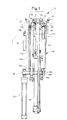
- Fig. 1 is a sectional view of essential parts of the center mechanism of the tire vulcanizing machine, showing an embodiment of the present invention.
- Fig. 2 is a plan view of Fig. 1 .
- Fig. 3 is an enlarged sectional view of a part A in Fig. 1 .
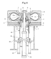
- Fig. 4 is a sectional view of the center mechanism of the tire vulcanizing machine.
- Fig. 4 shows a tire T being vulcanized, and a bladder B.
- a base of a body frame of a tire vulcanizing machine is indicated at 1.
- a lower heating platen 3 is fixed to the base 1 by bolts or the like via a heat insulating plate 2.
- a lower mold 4 is fixed to the lower heating platen 3 by bolts or the like.
- An upper mold 5 is fixed to a bolster plate (not shown), which has been assembled in an ascendable and descendable manner to the body frame, by bolts or the like via a heat insulating plate and an upper heating platen (not shown).
- An upper bead ring 6 is bolted to the upper mold 5.
- An upper clamp ring 8 is adapted to hold an upper opening end part of the bladder B, and a clamp plate 7 is bolted to the upper clamp ring 8, whereby the upper opening end part of the bladder B can be grasped.
- a lock ring 9 is bisected in a circumferential direction, and a center post (a piston rod of a cylinder 19 for extending and retracting of the center post) 10 has an upper end part integrated with the bisected lock ring 9 by bolting together with the upper clamp ring 8 being inserted. In this manner, the upper clamp ring 8 is fixed to the upper end part of the center post 10.
- a sealing member is interposed between the center post 10 and the upper clamp ring 8.
- a lower clamp ring 12 is adapted to hold a lower opening end part of the bladder B, and a lower bead ring 11 is bolted to the lower clamp ring 12, whereby the lower opening end part of the bladder B can be grasped.
- a hub (lower ring) 13 has an outer peripheral part to which the lower clamp ring 12 is fixed by screwing.
- a sealing member is interposed between the hub 13 and the lower clamp ring 12.
- An assembly 16 of a sealing member and a bushing is inserted into an inner peripheral part of the hub 13 via a cylindrical case 13b, and is held in place by a circulation head 15 fastened to the hub 13 by a plurality of (six in the illustrated embodiment) bolts 14.
- a circulation head 15 fastened to the hub 13 by a plurality of (six in the illustrated embodiment) bolts 14.
- the cylindrical case 13b is integrated with the inner peripheral part of the hub 13 by welding.
- An upper end part of a heating and pressurizing media passage 13a provided within the hub 13 opens into the bladder B via a nozzle hole 15a provided in the circulation head 15.
- a lower end part of the heating and pressurizing media passage 13a is connected to a heating and pressurizing media supply and discharge device (not shown) via a heating and pressuring media supply pipe 17a and a heating and pressuring media discharge pipe 17b fixed thereto by screwing-in or the like.
- a cylindrical spacer 18 having a structure to be described later is integrated with the hub 13.
- the center post drive cylinder 19 has a flange 19a provided in a vertically intermediate part of the cylinder 19, and the flange 19a is bolted to a bottom wall portion 18c of the spacer 18.
- the center post drive cylinder 19 is actuated to extend or retract the aforementioned center post (the piston rod of the center post drive cylinder 19) 10, thereby expanding or contracting the bladder B in the vertical direction.
- a guide tube 20 is fastened to an inner peripheral part of the lower heating platen 3 by a plurality of (six in the illustrated embodiment) bolts 21.
- the hub 13 moving integrally with the spacer 18 is fitted, in an ascendable and descendable manner, inwardly of a bushing 22 inserted into and fixed to the inner periphery of the guide tube 20.
- Bead lift cylinders 23 are bolted to brackets 24 fixed to the base 1, and upper end parts of piston rods 23a of the bead lift cylinders 23 are connected to a flange 25 of the above spacer 18.
- the bead lift cylinders 23 are actuated to raise or lower the center post drive cylinder 19, the spacer 18, the hub 13, the lower bead ring 11, and the lower clamp ring 12.
- the aforementioned hub 13 and the cylindrical spacer 18, both made of stainless steel or the like, are bound together by a plurality of (six in the illustrated embodiment) bolts 27 via a heat insulating material 26 in the form of a ring plate.
- the spacer 18 has a cylindrical body portion 18a to whose upper end part an inward flange portion 18b larger in thickness than the cylindrical bodyportion 18a is welded for integration, and the above-mentioned bolts 27 are screwed into the inward flange portion 18b.
- a bottom wall portion 18c larger in thickness than the cylindrical body portion 18a is also integrated with a lower end part of the cylindrical body portion 18a by welding.
- the bottom wall portion 18c is connected to the aforementioned flange 25 and the flange 19a of the center post drive cylinder 19 by bolts 28a and 28b, respectively (see Fig. 1 ).
- two whirl-prevention pins (whirl-prevention means) 29 are interposed at positions in point symmetry while penetrating the heat insulating material 26.
- two slots 13d elongated in the radial direction are formed in the lower surface of the hub 13 around the holes through which the above-mentioned predetermined two bolts 27 are inserted (see Fig. 2 ).
- two shallow holes 30 are formed to be located around the threadedholes, into which the above twobolts 27 are screwed, and concentrically with the threaded holes.
- whirl-prevention pins 29 of a cylindrical shape penetrating the heat insulating material 26 engage both with the slots 13d and the shallow holes 30 while being penetrated by the above-mentioned bolts 27.
- a threaded portion 13c allows the lower clamp ring 12 to be screwed thereon.
- the hub 13 and the spacer 18 descend, together with the center post cylinder 19, by the retracting action of the bead lift cylinder 23, whereby the unvulcanized tire T is positioned in the lower mold 4. Also, the leading end of the center post (piston rod) 10 protruding above the hub 13 is retracted by the center post cylinder 19, so that the bladder B grasped by the lower clamp ring 12 and the upper clamp ring 8 is inserted along the inner surface of the unvulcanized tire T set within the upper and lower molds 5 and 4.
- a heating and pressurizing media are fed from the heating and pressurizing media supply and discharge device (not shown) via the following route, heating and pressurizing media supply pipe 17a ⁇ heating and pressurizing media passage 13a ⁇ nozzle hole 15a of circulation head 15, and supplied into the bladder B, whereby the tire is vulcanized at a high temperature, for example, close to 200°C.
- the heating and pressurizing medium inside of the tire T is discharged, and then the uppermold 5 is raised. Then, the inside of the bladder B is vacuumized, and the center post drive cylinder 19 is operated to be extended, thereby raising the upper clamp ring 8. Thus, the bladder B is collapsed in diameter and extended upward, and is stripped from the tire T. Then, the bead lift cylinder 23 is operated to be extended, thereby raising the lower bead ring 11 to push up and strip the tire T from the lower mold 4. Whereafter the tire T is taken out of the apparatus by a publicly known means. Then, a tire T to be vulcanized next is brought in.
- the brought-in tire T is shaped, and the upper mold 5 is lowered.
- the heating and pressurizing media are fed into the tire T via the bladder B, as described above, to carry out the vulcanization step.
- the center mechanism is of a segmented structure in which the hub 13 and the spacer 18 are formed as the separate members and bound together by the bolts 27.
- the commonality of the components can be achieved (with the vulcanizing machine having two of the molds and two of the center mechanism arranged at the left and right sides, for example, it does not matter which of the right side and the left side the hub 13 and the spacer 18 should be located on).
- the heat insulating material 26 is interposed between the hub 13 and the spacer 18.
- a high temperature for example, close to 200°C is restrained from being transferred from the hub 13 to the spacer 18, whereby the energy loss is curtailed.
- thermal adverse influence on the center post drive cylinder 19 and the bead lift cylinder 23 upon heating is avoided.
- the temperature fall of the lower bead ring 11 screwed to the threaded portion 13c of the hub 13 can be suppressed, and the quality of the tire is improved.
- the hub 13 and the spacer 18 are bound together by the bolts 27.
- the dismounting operation is simplified, and enormous time and labor are unnecessary.
- the mounting operation is simplified, and enormous time and labor are unnecessary.
- the hub 13 and the spacer 18 in the interconnected state have to be disassembled from the base 1 and, in this state, the heating and pressurizing media supply pipe 17a and the heating and pressurizing media discharge pipe 17b have to be detached, whereafter the hub 13 must be helically turned and removed from the spacer 18.
- the hub 13 can be easily pulled out upward, together with the heating and pressurizing media supply pipe 17a and the heating and pressurizing media discharge pipe 17b, with the spacer 18 being assembled to the base 1.
- the whirl-prevention pins 29 engaging both with the hub 13 and the spacer 18 are installed.
- the turning of the hub 13 can be reliably prevented by the whirl-prevention pins 29. Its turning moment acting on the bolts 27 to damage the bolts 27, for example, can also be prevented.
- the present invention is not limited to the above embodiment, and various changes and modifications may be made without departing from the gist of the invention.
- the number of the bolts 27 binding the hub 13 and the spacer 18 can be changed, or the spacer 18 composed of the cylindrical body portion 18a, the inward flange portion 18b and the bottom wall portion 18c can be integrally formed.
- keys may be used instead of the whirl-prevention pins 29.
- the center post 10 may be formed as a member separate from the center post drive cylinder 19, and may be coupled to the piston rod of the cylinder 19.
- the center mechanism of the tire vulcanizing machine according to the present invention ensures commonality of the components. Thus, it is preferred when used in a multiple vulcanizing apparatus comprising a plurality of molds and center mechanisms arranged side by side.
- Patent Document 1 Japanese Patent 3300744
Landscapes
- Engineering & Computer Science (AREA)
- Mechanical Engineering (AREA)
- Physics & Mathematics (AREA)
- Health & Medical Sciences (AREA)
- Oral & Maxillofacial Surgery (AREA)
- Thermal Sciences (AREA)
- Moulds For Moulding Plastics Or The Like (AREA)
- Heating, Cooling, Or Curing Plastics Or The Like In General (AREA)
Abstract
Description
- This invention relates to a center mechanism of a tire vulcanizing machine used in a manufacturing process of a pneumatic tire which is mounted on an automobile or the like.
- This type of center mechanism of a tire vulcanizing machine, as shown, for example, in
Fig. 5 , has hitherto been composed of a hub portion (lower ring portion) 100a, which a lower clamp ring for holding a lower part of a bladder (not shown) is screwed into and fixed to; acylindrical spacer portion 100b connected to thehub portion 100a for raising and lowering the bladder and the lower clamp ring; and aguide tube 103 fixed to an inner peripheral part of alower heating platen 102 on abase 101, thehub portion 100a and thespacer portion 100b being fitted in theguide tube 103 so as to be ascendable and descendable. - Heating and pressurizing
media passages 104 are formed within thehub portion 100a, and a heating and pressurizingmedia supply pipe 105a and a heating and pressurizingmedia discharge pipe 105b are connected to the heating and pressurizingmedia passages 104 by screwing-in or the like. Acirculation head 106 is bolted onto the upper surface of thehub portion 100a, and a nozzle hole (not shown) of thecirculation head 106 is in communication with one of the above-mentioned heating and pressurizingmedia passage 104. - A bottom wall part of the
spacer portion 100b is bolted to aflange 107, and acenter post cylinder 108 is upwardly passed through and supported by theflange 107. Apiston rod 108a of the centerpost cylinder 108 penetrates the above-mentionedhub portion 100a andcirculation head 106 to be slidable in a vertical direction, and has a leading end to which an upper clamp ring for holding an upper part of the bladder (not shown) can be secured. - A piston rod leading end of a
bead lift cylinder 109, which has been supported upwardly by a bracket (not shown) on thebase 101, is fixed to theflange 107. By the extending and contracting action of thebead lift cylinder 109, the above-mentionedhub portion 100a andspacer portion 100b are allowed to ascend and descend together with thecenter post cylinder 108. - Before vulcanization of a tire, therefore, the descending action of the
hub portion 100a and thespacer portion 100b by the retracting action of thebead lift cylinder 109 together with the centerpost cylinder 108 positions thehub portion 100a and thespacer portion 100b onto the lower mold, while the leading end of thepiston rod 108a protruding above thehub portion 100a is retracted by thecenter post cylinder 108, whereby the bladder grasped by lower clamp ring and upper clamp ring is inserted along the inside surface of unvulcanized tire set on a lower mold (not shown). - In this state, a heating and pressurizing media are fed into the bladder from a heating and pressurizing media supply and discharge device (not shown) via the following route, heating and pressurizing
media supply pipe 105a → heating and pressurizingmedia passage 104 → nozzle hole ofcirculation head 106, whereby the tire is vulcanized at a high temperature close to 200°C. - With the above-mentioned center mechanism, the
hub portion 100a and thespacer portion 100b form an integrated structure, meaning that thehub portion 100a and thespacer portion 100b are formed as separate members, and then welded together. This has posed, for example, the following problems: (1) A plurality of steps, ranging from primary machining, welding and to finishing, are needed, and each step requires due care for precision and positioning. (2) Production by manufacturers other than those well-equipped with machining devices and welding machines incurs losses in manufacturing man-hours and transportation costs, and presents a cause for deterioration in quality. (3) If a weld defect is found after welding, it cannot be repaired. (4) Since heat during vulcanization is transmitted to thehub portion 100a, and then to thespacer portion 100b, heat radiation becomes so great that an energy loss occurs. - In recent years, therefore, there has been a center mechanism, as disclosed in
Patent Document 1, in which a hub and a spacer are formed as separate members, and the spacer is screwed into and bound to the hub. With this center mechanism, the problems (1) to (3) mentioned above have been resolved, but the problem (4) of energy loss has remained unsolved, and the following problem has been involved: Because of the structure in which the spacer is screwed into the hub, mounting and dismounting operations for disassembly and repair, replacement, etc. of the hub are complicated, requiring enormous time and labor. - That is, with such a structure that a hub is rotated at the screw thread connection, it is impossible to helically rotate the hub alone, because the lower end parts of the heating and pressurizing media supply pipe and the heating and pressurizing media discharge pipe connected on the hub penetrate the bottom wall part of the spacer, etc. Thus, if the hub is to be dismounted, for example, the hub and the spacer in the interconnected state have to be once disassembled from the base (101) and, in this state, the heating and pressurizing media supply pipe and the heating and pressurizing media discharge pipe have to be detached, whereafter the hub must be helically rotated and removed from the spacer.
- It is an obj ect of the present invention, therefore, to provide a center mechanism of a tire vulcanizing machine, which can achieve a decrease inman-hours and an improvement in quality and easily permits commonality of components, disassembly and repair as well as replacement.
- A first aspect of the present invention for attaining the above object is a center mechanism of a tire vulcanizing machine, including an upper clamp ring for holding an upper opening end part of a bladder, a lower clamp ring for holding a lower opening end part of the bladder, a hub on a lower mold side for supporting the lower clamp ring, a spacer connected to the hub and supported on the lower mold side to be ascendable and descendable, and a center post supported by the spacer to be extendable and retractable,
wherein the hub and the spacer are formed as members separate from each other, and are divisibly bound to each other by bolts. - According to a second aspect of the present invention, a heat insulating material may be interposed between the hub and the spacer.
- According to a third aspect of the present invention, whirl-prevention means may be provided between the hub and the spacer.
- According to the center mechanism of a tire vulcanizing machine concerned with the present invention, the center mechanism is of a segmented structure in which the hub and the spacer are formed as the separate members and bound together by the bolts. Thus, a decrease in the number of the processing steps and an improvement in the quality can be achieved, because of abolition of welding or the like strongly affecting the quality. Also, during the disassembly and repair, replacement, etc. of the hub due to wear or the like of the threaded portion upon mounting and dismounting of the lower clamp ring, when the hub is to be dismounted, for example, it suffices to loosen the bolts and pull out the hub upward. In comparison with the conventional structure requiring rotation of the hub at screw thread system, the dismounting operation is simplified, and enormous time and labor are unnecessary. For the mounting of the hub, only the reverse of the above-mentioned action is sufficient. The mounting operation is simplified, and enormous time and labor are unnecessary.
-
-
Fig. 1 is a sectional view of essential parts of a center mechanism of a tire vulcanizing machine, showing an embodiment of the present invention. -
Fig. 2 is a plan view ofFig. 1 . -
Fig. 3 is an enlarged sectional view of a part A inFig. 1 . -
Fig. 4 is a sectional view of the center mechanism of the tire vulcanizing machine. -
Fig. 5 is a sectional view of essential parts of a center mechanism of a tire vulcanizing machine according an earlier technology. - A center mechanism of a tire vulcanizing machine according to the present invention will now be described in detail by an embodiment with reference to the accompanying drawings.
-
Fig. 1 is a sectional view of essential parts of the center mechanism of the tire vulcanizing machine, showing an embodiment of the present invention.Fig. 2 is a plan view ofFig. 1 .Fig. 3 is an enlarged sectional view of a part A inFig. 1 .Fig. 4 is a sectional view of the center mechanism of the tire vulcanizing machine. -
Fig. 4 shows a tire T being vulcanized, and a bladder B. A base of a body frame of a tire vulcanizing machine is indicated at 1. A lower heating platen 3 is fixed to thebase 1 by bolts or the like via aheat insulating plate 2. A lower mold 4 is fixed to the lower heating platen 3 by bolts or the like. Anupper mold 5 is fixed to a bolster plate (not shown), which has been assembled in an ascendable and descendable manner to the body frame, by bolts or the like via a heat insulating plate and an upper heating platen (not shown). Anupper bead ring 6 is bolted to theupper mold 5. - An
upper clamp ring 8 is adapted to hold an upper opening end part of the bladder B, and aclamp plate 7 is bolted to theupper clamp ring 8, whereby the upper opening end part of the bladder B can be grasped. Alock ring 9 is bisected in a circumferential direction, and a center post (a piston rod of acylinder 19 for extending and retracting of the center post) 10 has an upper end part integrated with the bisectedlock ring 9 by bolting together with theupper clamp ring 8 being inserted. In this manner, theupper clamp ring 8 is fixed to the upper end part of thecenter post 10. A sealing member is interposed between thecenter post 10 and theupper clamp ring 8. - In
Figs. 1 ,2 and4 , alower clamp ring 12 is adapted to hold a lower opening end part of the bladder B, and alower bead ring 11 is bolted to thelower clamp ring 12, whereby the lower opening end part of the bladder B can be grasped. A hub (lower ring) 13 has an outer peripheral part to which thelower clamp ring 12 is fixed by screwing. A sealing member is interposed between thehub 13 and thelower clamp ring 12. - An
assembly 16 of a sealing member and a bushing is inserted into an inner peripheral part of thehub 13 via acylindrical case 13b, and is held in place by acirculation head 15 fastened to thehub 13 by a plurality of (six in the illustrated embodiment)bolts 14. Inwardly of theassembly 16 of the sealing member and the bushing, the above-mentionedcenter post 10 is fitted to be ascendable and descendable. Thecylindrical case 13b is integrated with the inner peripheral part of thehub 13 by welding. An upper end part of a heating and pressurizingmedia passage 13a provided within thehub 13 opens into the bladder B via anozzle hole 15a provided in thecirculation head 15. A lower end part of the heating and pressurizingmedia passage 13a is connected to a heating and pressurizing media supply and discharge device (not shown) via a heating and pressuringmedia supply pipe 17a and a heating and pressuringmedia discharge pipe 17b fixed thereto by screwing-in or the like. - A
cylindrical spacer 18 having a structure to be described later is integrated with thehub 13. The centerpost drive cylinder 19 has aflange 19a provided in a vertically intermediate part of thecylinder 19, and theflange 19a is bolted to abottom wall portion 18c of thespacer 18. The centerpost drive cylinder 19 is actuated to extend or retract the aforementioned center post (the piston rod of the center post drive cylinder 19) 10, thereby expanding or contracting the bladder B in the vertical direction. - A
guide tube 20 is fastened to an inner peripheral part of the lower heating platen 3 by a plurality of (six in the illustrated embodiment)bolts 21. Thehub 13 moving integrally with thespacer 18 is fitted, in an ascendable and descendable manner, inwardly of abushing 22 inserted into and fixed to the inner periphery of theguide tube 20.Bead lift cylinders 23 are bolted tobrackets 24 fixed to thebase 1, and upper end parts of piston rods 23a of thebead lift cylinders 23 are connected to aflange 25 of theabove spacer 18. Thebead lift cylinders 23 are actuated to raise or lower the centerpost drive cylinder 19, thespacer 18, thehub 13, thelower bead ring 11, and thelower clamp ring 12. - As shown in
Fig. 3 , theaforementioned hub 13 and thecylindrical spacer 18, both made of stainless steel or the like, are bound together by a plurality of (six in the illustrated embodiment)bolts 27 via aheat insulating material 26 in the form of a ring plate. - The
spacer 18 has acylindrical body portion 18a to whose upper end part aninward flange portion 18b larger in thickness than thecylindrical bodyportion 18a is welded for integration, and the above-mentionedbolts 27 are screwed into theinward flange portion 18b. Abottom wall portion 18c larger in thickness than thecylindrical body portion 18a is also integrated with a lower end part of thecylindrical body portion 18a by welding. Thebottom wall portion 18c is connected to theaforementioned flange 25 and theflange 19a of the centerpost drive cylinder 19 bybolts Fig. 1 ). - Between the
hub 13 and thespacer 18, two whirl-prevention pins (whirl-prevention means) 29 are interposed at positions in point symmetry while penetrating theheat insulating material 26. In the illustrated embodiment, twoslots 13d elongated in the radial direction are formed in the lower surface of thehub 13 around the holes through which the above-mentioned predetermined twobolts 27 are inserted (seeFig. 2 ). In the upper surface of theinward flange portion 18b as well, twoshallow holes 30 are formed to be located around the threadedholes, into which theabove twobolts 27 are screwed, and concentrically with the threaded holes. The whirl-prevention pins 29 of a cylindrical shape penetrating theheat insulating material 26 engage both with theslots 13d and theshallow holes 30 while being penetrated by the above-mentionedbolts 27. InFig. 3 , a threadedportion 13c allows thelower clamp ring 12 to be screwed thereon. - Before vulcanization of the tire T in the apparatus of the above-described configuration, the
hub 13 and thespacer 18 descend, together with thecenter post cylinder 19, by the retracting action of thebead lift cylinder 23, whereby the unvulcanized tire T is positioned in the lower mold 4. Also, the leading end of the center post (piston rod) 10 protruding above thehub 13 is retracted by thecenter post cylinder 19, so that the bladder B grasped by thelower clamp ring 12 and theupper clamp ring 8 is inserted along the inner surface of the unvulcanized tire T set within the upper andlower molds 5 and 4. - In this state, a heating and pressurizing media are fed from the heating and pressurizing media supply and discharge device (not shown) via the following route, heating and pressurizing
media supply pipe 17a → heating and pressurizingmedia passage 13a →nozzle hole 15a ofcirculation head 15, and supplied into the bladder B, whereby the tire is vulcanized at a high temperature, for example, close to 200°C. - After the vulcanization of the tire T is completed, the heating and pressurizing medium inside of the tire T is discharged, and then the
uppermold 5 is raised. Then, the inside of the bladder B is vacuumized, and the centerpost drive cylinder 19 is operated to be extended, thereby raising theupper clamp ring 8. Thus, the bladder B is collapsed in diameter and extended upward, and is stripped from the tire T. Then, thebead lift cylinder 23 is operated to be extended, thereby raising thelower bead ring 11 to push up and strip the tire T from the lower mold 4. Whereafter the tire T is taken out of the apparatus by a publicly known means. Then, a tire T to be vulcanized next is brought in. - Then, the brought-in tire T is shaped, and the
upper mold 5 is lowered. Upon closure of the mold, the heating and pressurizing media are fed into the tire T via the bladder B, as described above, to carry out the vulcanization step. - In the present embodiment, as stated above, the center mechanism is of a segmented structure in which the
hub 13 and thespacer 18 are formed as the separate members and bound together by thebolts 27. Thus, a decrease in the number of the processing steps and an improvement in the qualitycanbe achieved, because of abolition of welding or the like strongly affecting the quality. Also, the commonality of the components can be achieved (with the vulcanizing machine having two of the molds and two of the center mechanism arranged at the left and right sides, for example, it does not matter which of the right side and the left side thehub 13 and thespacer 18 should be located on). - The
heat insulating material 26 is interposed between thehub 13 and thespacer 18. Thus, the heat during vulcanization at a high temperature, for example, close to 200°C is restrained from being transferred from thehub 13 to thespacer 18, whereby the energy loss is curtailed. Moreover, thermal adverse influence on the centerpost drive cylinder 19 and thebead lift cylinder 23 upon heating is avoided. On the other hand, the temperature fall of thelower bead ring 11 screwed to the threadedportion 13c of thehub 13 can be suppressed, and the quality of the tire is improved. - The
hub 13 and thespacer 18 are bound together by thebolts 27. Thus, during the disassembly and repair, replacement, etc. of thehub 13 due to wear or the like of the threadedportion 13c upon mounting and dismounting of thelower clamp ring 12, when thehub 13 is to be dismounted, for example, it suffices to loosen thebolts 27 and pull out thehub 13 upward. In comparison with the conventional structure requiring turning thehub 13 due to screw thread connection system, the dismounting operation is simplified, and enormous time and labor are unnecessary. For the mounting of thehub 13, only the reverse of the above-mentioned action is sufficient. The mounting operation is simplified, and enormous time and labor are unnecessary. - With the conventional structure requiring turning the
hub 13 due to screw thread connection system, the lower end parts of the heating and pressurizingmedia supply pipe 17a and the heating and pressurizingmedia discharge pipe 17b connected to thehub 13 penetrate thebottom wall portion 18c of thespacer 18 and theflange 25. This makes it impossible to helically turn thehub 13 alone. In dismounting thehub 13, for example, thehub 13 and thespacer 18 in the interconnected state have to be disassembled from thebase 1 and, in this state, the heating and pressurizingmedia supply pipe 17a and the heating and pressurizingmedia discharge pipe 17b have to be detached, whereafter thehub 13 must be helically turned and removed from thespacer 18. In the present embodiment, by contrast, thehub 13 can be easily pulled out upward, together with the heating and pressurizingmedia supply pipe 17a and the heating and pressurizingmedia discharge pipe 17b, with thespacer 18 being assembled to thebase 1. - The whirl-prevention pins 29 engaging both with the
hub 13 and thespacer 18 are installed. Thus, when thelower clamp ring 12 screwed to the threadedportion 13c of thehub 13 is to be mounted or removed by helical turning in order to change the size of the tire T, for example, the turning of thehub 13 can be reliably prevented by the whirl-prevention pins 29. Its turning moment acting on thebolts 27 to damage thebolts 27, for example, can also be prevented. - It goes without saying that the present invention is not limited to the above embodiment, and various changes and modifications may be made without departing from the gist of the invention. For example, the number of the
bolts 27 binding thehub 13 and thespacer 18 can be changed, or thespacer 18 composed of thecylindrical body portion 18a, theinward flange portion 18b and thebottom wall portion 18c can be integrally formed. Furthermore, keys may be used instead of the whirl-prevention pins 29. Besides, thecenter post 10 may be formed as a member separate from the centerpost drive cylinder 19, and may be coupled to the piston rod of thecylinder 19. - The center mechanism of the tire vulcanizing machine according to the present invention ensures commonality of the components. Thus, it is preferred when used in a multiple vulcanizing apparatus comprising a plurality of molds and center mechanisms arranged side by side.
-
- 1
- Base
- 2
- Heat insulating plate
- 3
- Lower heating platen
- 4
- Lower mold
- 5
- Upper mold
- 6
- Upper bead ring
- 7
- Clamp plate
- 8
- Upper clamp ring
- 9
- Lock ring
- 10
- Center post
- 11
- Lower bead ring
- 12
- Lower clamp ring
- 13
- Hub
- 13a
- Heating and pressurizing media passage
- 13b
- Cylindrical case
- 13c
- Threaded portion
- 13d
- Slot
- 14
- Bolt
- 15
- Circulation head
- 15a
- Nozzle hole
- 16
- Assembly of sealing member and bushing
- 17a
- Heating and pressurizing media supply pipe
- 17b
- Heating and pressurizing media discharge pipe
- 18
- Spacer
- 18a
- Cylindrical body portion
- 18b
- Inward flange portion
- 18c
- Bottom wall portion
- 19
- Center post drive cylinder
- 19a
- Flange
- 20
- Guide tube
- 21
- Bolt
- 22
- Bushing
- 23
- Bead lift cylinder
- 23a
- Piston rod
- 24
- Bracket
- 25
- Flange
- 26
- Heat insulating material
- 27
- Bolt
- 28a, 28b
- Bolt
- 29
- Whirl-prevention pin
- 30
- Shallow hole
- B
- Bladder
- T
- Tire
- Patent Document 1: Japanese Patent
3300744
Claims (3)
- A center mechanism of a tire vulcanizing machine, including an upper clamp ring (8) for grasping an upper opening end part of a bladder (B) , a lower clamp ring (12) for grasping a lower opening end part of the bladder, a hub (13) on a side of a lower mold (4) for supporting the lower clamp ring, a spacer (18) connected to the hub and supported on the side of the lower mold to be ascendable and descendable, and a center post (10) supported by the spacer to be extensible and contractible,
characterized in that the hub (13) and the spacer (18) are formed as members separate from each other, and are divisibly bound to each other by bolts (27). - The center mechanism of a tire vulcanizing machine according to claim 1, characterized in that a heat insulating material (26) interposed between the hub (13) and the spacer (18).
- The center mechanism of a tire vulcanizing machine according to claim 1 or 2, characterized in that whirl-prevention means (29) provided between the hub (13) and the spacer (18).
Applications Claiming Priority (1)
| Application Number | Priority Date | Filing Date | Title |
|---|---|---|---|
| JP2009095613A JP5469361B2 (en) | 2009-04-10 | 2009-04-10 | Central mechanism of tire vulcanizer |
Publications (2)
| Publication Number | Publication Date |
|---|---|
| EP2239129A1 true EP2239129A1 (en) | 2010-10-13 |
| EP2239129B1 EP2239129B1 (en) | 2011-12-14 |
Family
ID=42269738
Family Applications (1)
| Application Number | Title | Priority Date | Filing Date |
|---|---|---|---|
| EP09170220A Not-in-force EP2239129B1 (en) | 2009-04-10 | 2009-09-14 | Center mechanism of tire vulcanizing machine |
Country Status (6)
| Country | Link |
|---|---|
| US (1) | US8133046B2 (en) |
| EP (1) | EP2239129B1 (en) |
| JP (1) | JP5469361B2 (en) |
| KR (1) | KR101109981B1 (en) |
| CN (1) | CN101856847B (en) |
| AT (1) | ATE536987T1 (en) |
Families Citing this family (9)
| Publication number | Priority date | Publication date | Assignee | Title |
|---|---|---|---|---|
| US9430286B2 (en) * | 2011-12-12 | 2016-08-30 | International Business Machines Corporation | Authorizing distributed task processing in a distributed storage network |
| JP5748683B2 (en) | 2012-02-03 | 2015-07-15 | 三菱重工マシナリーテクノロジー株式会社 | Tire vulcanizer |
| JP5259007B1 (en) | 2012-11-05 | 2013-08-07 | 三菱重工マシナリーテクノロジー株式会社 | Tire vulcanizer and maintenance method of tire vulcanizer |
| CN103909596B (en) * | 2014-03-19 | 2016-01-27 | 和承汽车配件(太仓)有限公司 | A kind of non-return clip of anti-rubber tube sulfuration distortion |
| JP6735079B2 (en) * | 2015-10-15 | 2020-08-05 | Toyo Tire株式会社 | Bladder fixing unit |
| CN105500560B (en) * | 2016-01-27 | 2017-10-10 | 萨驰华辰机械(苏州)有限公司 | A kind of fast mold change mechanism of tire |
| CN110239125A (en) * | 2018-03-09 | 2019-09-17 | 四川轮胎橡胶(集团)股份有限公司 | Bladder fixture for B-type tire shaping and vulcanizing machine |
| CN112454767B (en) * | 2020-10-23 | 2022-05-03 | 杭州朝阳橡胶有限公司 | Tire hydraulic vulcanizing machine central mechanism and flue gas collecting method thereof |
| US20240042715A1 (en) * | 2022-08-04 | 2024-02-08 | Larsen & Toubro Limited | Bladder control assembly for tire curing press |
Citations (4)
| Publication number | Priority date | Publication date | Assignee | Title |
|---|---|---|---|---|
| DE4024435A1 (en) * | 1989-08-02 | 1991-02-07 | Mitsubishi Heavy Ind Ltd | CENTRAL MECHANISM OF A TIRE VOLCANIZING MACHINE |
| US5149545A (en) * | 1990-03-26 | 1992-09-22 | Mitsubishi Jukogyo Kabushiki Kaisha | Central mechanism of tire vulcanizer |
| WO2001032388A1 (en) * | 1999-10-29 | 2001-05-10 | Ichimaru Giken Co., Ltd. | Automatic clamping device of tire vulcanizing device |
| JP3300744B2 (en) | 1996-09-03 | 2002-07-08 | 三菱重工業株式会社 | Central mechanism of tire vulcanizer |
Family Cites Families (9)
| Publication number | Priority date | Publication date | Assignee | Title |
|---|---|---|---|---|
| JPS5628844A (en) * | 1979-08-17 | 1981-03-23 | Kobe Steel Ltd | Central mechanism of tyre vulcanizing machine |
| JPS57188338A (en) * | 1981-04-21 | 1982-11-19 | Kobe Steel Ltd | Central mechanism for tire vulcanizing machine |
| JPS59192546A (en) * | 1983-04-07 | 1984-10-31 | Kobe Steel Ltd | Center mechanism of tire vulcanizing machine |
| JPH0637058A (en) | 1992-07-17 | 1994-02-10 | Toshiba Corp | Dry etching method |
| US5601850A (en) * | 1993-05-07 | 1997-02-11 | Kabushiki Kaisha Kobe Seiko Sho | Center mechanism of tire vulcanizing press |
| JPH1080920A (en) * | 1996-09-09 | 1998-03-31 | Mitsubishi Heavy Ind Ltd | Central mechanism for tire vulcanizer |
| US6416305B1 (en) * | 1998-10-26 | 2002-07-09 | Mcneil & Nrm, Inc. | Tire curing press center mechanism |
| CN2585743Y (en) * | 2002-12-30 | 2003-11-12 | 福建华橡自控技术股份有限公司 | B-type separating central mechanism of tyre vulcanizer |
| US7513763B1 (en) * | 2007-06-04 | 2009-04-07 | Mcneil & Nrm, Inc. | Tire press center mechanism |
-
2009
- 2009-04-10 JP JP2009095613A patent/JP5469361B2/en not_active Expired - Fee Related
- 2009-09-14 AT AT09170220T patent/ATE536987T1/en active
- 2009-09-14 EP EP09170220A patent/EP2239129B1/en not_active Not-in-force
- 2009-09-15 US US12/559,655 patent/US8133046B2/en not_active Expired - Fee Related
- 2009-09-28 CN CN2009101787225A patent/CN101856847B/en not_active Expired - Fee Related
- 2009-09-29 KR KR1020090092267A patent/KR101109981B1/en not_active Expired - Fee Related
Patent Citations (4)
| Publication number | Priority date | Publication date | Assignee | Title |
|---|---|---|---|---|
| DE4024435A1 (en) * | 1989-08-02 | 1991-02-07 | Mitsubishi Heavy Ind Ltd | CENTRAL MECHANISM OF A TIRE VOLCANIZING MACHINE |
| US5149545A (en) * | 1990-03-26 | 1992-09-22 | Mitsubishi Jukogyo Kabushiki Kaisha | Central mechanism of tire vulcanizer |
| JP3300744B2 (en) | 1996-09-03 | 2002-07-08 | 三菱重工業株式会社 | Central mechanism of tire vulcanizer |
| WO2001032388A1 (en) * | 1999-10-29 | 2001-05-10 | Ichimaru Giken Co., Ltd. | Automatic clamping device of tire vulcanizing device |
Also Published As
| Publication number | Publication date |
|---|---|
| EP2239129B1 (en) | 2011-12-14 |
| ATE536987T1 (en) | 2011-12-15 |
| CN101856847B (en) | 2013-07-24 |
| JP2010241090A (en) | 2010-10-28 |
| CN101856847A (en) | 2010-10-13 |
| JP5469361B2 (en) | 2014-04-16 |
| KR20100113012A (en) | 2010-10-20 |
| US20100260877A1 (en) | 2010-10-14 |
| KR101109981B1 (en) | 2012-02-15 |
| US8133046B2 (en) | 2012-03-13 |
Similar Documents
| Publication | Publication Date | Title |
|---|---|---|
| EP2239129B1 (en) | Center mechanism of tire vulcanizing machine | |
| TWI453131B (en) | After the vulcanization booster pump | |
| EP2915646B1 (en) | Tire vulcanizer and maintenance method of tire vulcanizer | |
| US5409361A (en) | Center mechanism of tire curing press | |
| US9688036B2 (en) | Post cure inflator | |
| EP2441557B1 (en) | Tire production method and device | |
| JP2010017952A (en) | Central mechanism for tire vulcanizer, and mold operating method for tire vulcanizer | |
| US5106280A (en) | Center mechanism of a tire vulcanizing machine | |
| EP0747190A2 (en) | Center mechanism for a tyre vulcanizer | |
| CN213227181U (en) | Quick installation locking mechanism of curing bladder | |
| CN202655741U (en) | Gear ring hobbing clamping tool | |
| EP2329941B1 (en) | Apparatus for cooling a tire, tire building press with such an apparatus and method of manufacturing a tire | |
| US6273698B1 (en) | Tire vulcanizing system | |
| JPH0970833A (en) | Device for replacing rim of post-cure inflator | |
| US4955799A (en) | Metal mold centering and clamping device in a tire vulcanizing machine | |
| WO2015159382A1 (en) | Tire vulcanizing device and tire vulcanizing method | |
| CN224011384U (en) | Clamp for gear shaft hobbing | |
| CN221049404U (en) | Tire replacement workstation | |
| CN204524724U (en) | Large-diameter hydraulic vertical prop is vertical tears cylinder machine open | |
| US20180250900A1 (en) | Method and Device for Manufacturing Tire Vulcanization Bladder Assembly | |
| CN120206697A (en) | Bladder manipulator and vulcanizing machine | |
| KR960009251Y1 (en) | Bladder replacement device for tire vulcanizer | |
| CN119188635A (en) | Reversing device for aircraft engine core | |
| CN120840134A (en) | A tire vulcanizing device with quick bladder replacement | |
| CN114211661A (en) | A kind of translational bladder vulcanizing machine and using method thereof |
Legal Events
| Date | Code | Title | Description |
|---|---|---|---|
| PUAI | Public reference made under article 153(3) epc to a published international application that has entered the european phase |
Free format text: ORIGINAL CODE: 0009012 |
|
| 17P | Request for examination filed |
Effective date: 20090914 |
|
| AK | Designated contracting states |
Kind code of ref document: A1 Designated state(s): AT BE BG CH CY CZ DE DK EE ES FI FR GB GR HR HU IE IS IT LI LT LU LV MC MK MT NL NO PL PT RO SE SI SK SM TR |
|
| AX | Request for extension of the european patent |
Extension state: AL BA RS |
|
| GRAP | Despatch of communication of intention to grant a patent |
Free format text: ORIGINAL CODE: EPIDOSNIGR1 |
|
| RIC1 | Information provided on ipc code assigned before grant |
Ipc: B29D 30/06 20060101AFI20110803BHEP Ipc: B29C 33/30 20060101ALI20110803BHEP |
|
| GRAS | Grant fee paid |
Free format text: ORIGINAL CODE: EPIDOSNIGR3 |
|
| GRAA | (expected) grant |
Free format text: ORIGINAL CODE: 0009210 |
|
| AK | Designated contracting states |
Kind code of ref document: B1 Designated state(s): AT BE BG CH CY CZ DE DK EE ES FI FR GB GR HR HU IE IS IT LI LT LU LV MC MK MT NL NO PL PT RO SE SI SK SM TR |
|
| REG | Reference to a national code |
Ref country code: GB Ref legal event code: FG4D |
|
| REG | Reference to a national code |
Ref country code: CH Ref legal event code: EP |
|
| RIN2 | Information on inventor provided after grant (corrected) |
Inventor name: TOMOTO, KEIICHI Inventor name: MURAKAMI, TOSHIFUMI Inventor name: HINENO, YOSHIKATSU |
|
| REG | Reference to a national code |
Ref country code: IE Ref legal event code: FG4D |
|
| REG | Reference to a national code |
Ref country code: DE Ref legal event code: R083 Ref document number: 602009004151 Country of ref document: DE |
|
| REG | Reference to a national code |
Ref country code: DE Ref legal event code: R096 Ref document number: 602009004151 Country of ref document: DE Effective date: 20120301 |
|
| REG | Reference to a national code |
Ref country code: NL Ref legal event code: VDEP Effective date: 20111214 |
|
| PG25 | Lapsed in a contracting state [announced via postgrant information from national office to epo] |
Ref country code: LT Free format text: LAPSE BECAUSE OF FAILURE TO SUBMIT A TRANSLATION OF THE DESCRIPTION OR TO PAY THE FEE WITHIN THE PRESCRIBED TIME-LIMIT Effective date: 20111214 Ref country code: NO Free format text: LAPSE BECAUSE OF FAILURE TO SUBMIT A TRANSLATION OF THE DESCRIPTION OR TO PAY THE FEE WITHIN THE PRESCRIBED TIME-LIMIT Effective date: 20120314 |
|
| LTIE | Lt: invalidation of european patent or patent extension |
Effective date: 20111214 |
|
| PG25 | Lapsed in a contracting state [announced via postgrant information from national office to epo] |
Ref country code: HR Free format text: LAPSE BECAUSE OF FAILURE TO SUBMIT A TRANSLATION OF THE DESCRIPTION OR TO PAY THE FEE WITHIN THE PRESCRIBED TIME-LIMIT Effective date: 20111214 Ref country code: SE Free format text: LAPSE BECAUSE OF FAILURE TO SUBMIT A TRANSLATION OF THE DESCRIPTION OR TO PAY THE FEE WITHIN THE PRESCRIBED TIME-LIMIT Effective date: 20111214 Ref country code: NL Free format text: LAPSE BECAUSE OF FAILURE TO SUBMIT A TRANSLATION OF THE DESCRIPTION OR TO PAY THE FEE WITHIN THE PRESCRIBED TIME-LIMIT Effective date: 20111214 Ref country code: SI Free format text: LAPSE BECAUSE OF FAILURE TO SUBMIT A TRANSLATION OF THE DESCRIPTION OR TO PAY THE FEE WITHIN THE PRESCRIBED TIME-LIMIT Effective date: 20111214 Ref country code: LV Free format text: LAPSE BECAUSE OF FAILURE TO SUBMIT A TRANSLATION OF THE DESCRIPTION OR TO PAY THE FEE WITHIN THE PRESCRIBED TIME-LIMIT Effective date: 20111214 Ref country code: GR Free format text: LAPSE BECAUSE OF FAILURE TO SUBMIT A TRANSLATION OF THE DESCRIPTION OR TO PAY THE FEE WITHIN THE PRESCRIBED TIME-LIMIT Effective date: 20120315 |
|
| PG25 | Lapsed in a contracting state [announced via postgrant information from national office to epo] |
Ref country code: BE Free format text: LAPSE BECAUSE OF FAILURE TO SUBMIT A TRANSLATION OF THE DESCRIPTION OR TO PAY THE FEE WITHIN THE PRESCRIBED TIME-LIMIT Effective date: 20111214 Ref country code: CY Free format text: LAPSE BECAUSE OF FAILURE TO SUBMIT A TRANSLATION OF THE DESCRIPTION OR TO PAY THE FEE WITHIN THE PRESCRIBED TIME-LIMIT Effective date: 20111214 |
|
| PG25 | Lapsed in a contracting state [announced via postgrant information from national office to epo] |
Ref country code: IS Free format text: LAPSE BECAUSE OF FAILURE TO SUBMIT A TRANSLATION OF THE DESCRIPTION OR TO PAY THE FEE WITHIN THE PRESCRIBED TIME-LIMIT Effective date: 20120414 Ref country code: BG Free format text: LAPSE BECAUSE OF FAILURE TO SUBMIT A TRANSLATION OF THE DESCRIPTION OR TO PAY THE FEE WITHIN THE PRESCRIBED TIME-LIMIT Effective date: 20120314 Ref country code: CZ Free format text: LAPSE BECAUSE OF FAILURE TO SUBMIT A TRANSLATION OF THE DESCRIPTION OR TO PAY THE FEE WITHIN THE PRESCRIBED TIME-LIMIT Effective date: 20111214 Ref country code: SK Free format text: LAPSE BECAUSE OF FAILURE TO SUBMIT A TRANSLATION OF THE DESCRIPTION OR TO PAY THE FEE WITHIN THE PRESCRIBED TIME-LIMIT Effective date: 20111214 Ref country code: EE Free format text: LAPSE BECAUSE OF FAILURE TO SUBMIT A TRANSLATION OF THE DESCRIPTION OR TO PAY THE FEE WITHIN THE PRESCRIBED TIME-LIMIT Effective date: 20111214 |
|
| PG25 | Lapsed in a contracting state [announced via postgrant information from national office to epo] |
Ref country code: PT Free format text: LAPSE BECAUSE OF FAILURE TO SUBMIT A TRANSLATION OF THE DESCRIPTION OR TO PAY THE FEE WITHIN THE PRESCRIBED TIME-LIMIT Effective date: 20120416 Ref country code: RO Free format text: LAPSE BECAUSE OF FAILURE TO SUBMIT A TRANSLATION OF THE DESCRIPTION OR TO PAY THE FEE WITHIN THE PRESCRIBED TIME-LIMIT Effective date: 20111214 Ref country code: PL Free format text: LAPSE BECAUSE OF FAILURE TO SUBMIT A TRANSLATION OF THE DESCRIPTION OR TO PAY THE FEE WITHIN THE PRESCRIBED TIME-LIMIT Effective date: 20111214 |
|
| REG | Reference to a national code |
Ref country code: AT Ref legal event code: MK05 Ref document number: 536987 Country of ref document: AT Kind code of ref document: T Effective date: 20111214 |
|
| PLBE | No opposition filed within time limit |
Free format text: ORIGINAL CODE: 0009261 |
|
| STAA | Information on the status of an ep patent application or granted ep patent |
Free format text: STATUS: NO OPPOSITION FILED WITHIN TIME LIMIT |
|
| PG25 | Lapsed in a contracting state [announced via postgrant information from national office to epo] |
Ref country code: DK Free format text: LAPSE BECAUSE OF FAILURE TO SUBMIT A TRANSLATION OF THE DESCRIPTION OR TO PAY THE FEE WITHIN THE PRESCRIBED TIME-LIMIT Effective date: 20111214 |
|
| 26N | No opposition filed |
Effective date: 20120917 |
|
| PGFP | Annual fee paid to national office [announced via postgrant information from national office to epo] |
Ref country code: IT Payment date: 20120930 Year of fee payment: 4 |
|
| REG | Reference to a national code |
Ref country code: DE Ref legal event code: R097 Ref document number: 602009004151 Country of ref document: DE Effective date: 20120917 |
|
| PG25 | Lapsed in a contracting state [announced via postgrant information from national office to epo] |
Ref country code: AT Free format text: LAPSE BECAUSE OF FAILURE TO SUBMIT A TRANSLATION OF THE DESCRIPTION OR TO PAY THE FEE WITHIN THE PRESCRIBED TIME-LIMIT Effective date: 20111214 |
|
| PG25 | Lapsed in a contracting state [announced via postgrant information from national office to epo] |
Ref country code: MC Free format text: LAPSE BECAUSE OF NON-PAYMENT OF DUE FEES Effective date: 20120930 |
|
| REG | Reference to a national code |
Ref country code: IE Ref legal event code: MM4A |
|
| PG25 | Lapsed in a contracting state [announced via postgrant information from national office to epo] |
Ref country code: FI Free format text: LAPSE BECAUSE OF FAILURE TO SUBMIT A TRANSLATION OF THE DESCRIPTION OR TO PAY THE FEE WITHIN THE PRESCRIBED TIME-LIMIT Effective date: 20111214 |
|
| REG | Reference to a national code |
Ref country code: FR Ref legal event code: ST Effective date: 20130531 |
|
| PG25 | Lapsed in a contracting state [announced via postgrant information from national office to epo] |
Ref country code: IE Free format text: LAPSE BECAUSE OF NON-PAYMENT OF DUE FEES Effective date: 20120914 |
|
| PG25 | Lapsed in a contracting state [announced via postgrant information from national office to epo] |
Ref country code: FR Free format text: LAPSE BECAUSE OF NON-PAYMENT OF DUE FEES Effective date: 20121001 |
|
| PG25 | Lapsed in a contracting state [announced via postgrant information from national office to epo] |
Ref country code: ES Free format text: LAPSE BECAUSE OF FAILURE TO SUBMIT A TRANSLATION OF THE DESCRIPTION OR TO PAY THE FEE WITHIN THE PRESCRIBED TIME-LIMIT Effective date: 20120325 |
|
| PG25 | Lapsed in a contracting state [announced via postgrant information from national office to epo] |
Ref country code: MT Free format text: LAPSE BECAUSE OF FAILURE TO SUBMIT A TRANSLATION OF THE DESCRIPTION OR TO PAY THE FEE WITHIN THE PRESCRIBED TIME-LIMIT Effective date: 20111214 |
|
| PG25 | Lapsed in a contracting state [announced via postgrant information from national office to epo] |
Ref country code: TR Free format text: LAPSE BECAUSE OF FAILURE TO SUBMIT A TRANSLATION OF THE DESCRIPTION OR TO PAY THE FEE WITHIN THE PRESCRIBED TIME-LIMIT Effective date: 20111214 |
|
| REG | Reference to a national code |
Ref country code: CH Ref legal event code: PL |
|
| GBPC | Gb: european patent ceased through non-payment of renewal fee |
Effective date: 20130914 |
|
| PG25 | Lapsed in a contracting state [announced via postgrant information from national office to epo] |
Ref country code: SM Free format text: LAPSE BECAUSE OF FAILURE TO SUBMIT A TRANSLATION OF THE DESCRIPTION OR TO PAY THE FEE WITHIN THE PRESCRIBED TIME-LIMIT Effective date: 20111214 Ref country code: LU Free format text: LAPSE BECAUSE OF NON-PAYMENT OF DUE FEES Effective date: 20120914 |
|
| PG25 | Lapsed in a contracting state [announced via postgrant information from national office to epo] |
Ref country code: LI Free format text: LAPSE BECAUSE OF NON-PAYMENT OF DUE FEES Effective date: 20130930 Ref country code: GB Free format text: LAPSE BECAUSE OF NON-PAYMENT OF DUE FEES Effective date: 20130914 Ref country code: HU Free format text: LAPSE BECAUSE OF FAILURE TO SUBMIT A TRANSLATION OF THE DESCRIPTION OR TO PAY THE FEE WITHIN THE PRESCRIBED TIME-LIMIT Effective date: 20090914 Ref country code: CH Free format text: LAPSE BECAUSE OF NON-PAYMENT OF DUE FEES Effective date: 20130930 |
|
| PG25 | Lapsed in a contracting state [announced via postgrant information from national office to epo] |
Ref country code: IT Free format text: LAPSE BECAUSE OF NON-PAYMENT OF DUE FEES Effective date: 20130914 |
|
| PG25 | Lapsed in a contracting state [announced via postgrant information from national office to epo] |
Ref country code: MK Free format text: LAPSE BECAUSE OF FAILURE TO SUBMIT A TRANSLATION OF THE DESCRIPTION OR TO PAY THE FEE WITHIN THE PRESCRIBED TIME-LIMIT Effective date: 20111214 |
|
| PGFP | Annual fee paid to national office [announced via postgrant information from national office to epo] |
Ref country code: DE Payment date: 20160907 Year of fee payment: 8 |
|
| REG | Reference to a national code |
Ref country code: DE Ref legal event code: R119 Ref document number: 602009004151 Country of ref document: DE |
|
| PG25 | Lapsed in a contracting state [announced via postgrant information from national office to epo] |
Ref country code: DE Free format text: LAPSE BECAUSE OF NON-PAYMENT OF DUE FEES Effective date: 20180404 |