EP2239104A1 - Floatable hand tool - Google Patents
Floatable hand tool Download PDFInfo
- Publication number
- EP2239104A1 EP2239104A1 EP09157783A EP09157783A EP2239104A1 EP 2239104 A1 EP2239104 A1 EP 2239104A1 EP 09157783 A EP09157783 A EP 09157783A EP 09157783 A EP09157783 A EP 09157783A EP 2239104 A1 EP2239104 A1 EP 2239104A1
- Authority
- EP
- European Patent Office
- Prior art keywords
- handle
- tool
- hand tool
- liquid
- hand
- Prior art date
- Legal status (The legal status is an assumption and is not a legal conclusion. Google has not performed a legal analysis and makes no representation as to the accuracy of the status listed.)
- Withdrawn
Links
- 239000007788 liquid Substances 0.000 claims abstract description 88
- 238000000034 method Methods 0.000 claims abstract description 13
- 238000005304 joining Methods 0.000 claims abstract description 6
- 230000005484 gravity Effects 0.000 claims description 38
- 239000000463 material Substances 0.000 claims description 35
- 238000007667 floating Methods 0.000 claims description 33
- 210000003811 finger Anatomy 0.000 claims description 31
- 238000009826 distribution Methods 0.000 claims description 24
- 210000003813 thumb Anatomy 0.000 claims description 16
- 229910000831 Steel Inorganic materials 0.000 claims description 13
- 239000010959 steel Substances 0.000 claims description 13
- 239000004033 plastic Substances 0.000 claims description 10
- 229920003023 plastic Polymers 0.000 claims description 10
- 239000002023 wood Substances 0.000 claims description 7
- 241000870659 Crassula perfoliata var. minor Species 0.000 claims description 6
- 239000006260 foam Substances 0.000 claims description 4
- 239000003292 glue Substances 0.000 claims description 4
- 239000000203 mixture Substances 0.000 claims description 3
- 239000011797 cavity material Substances 0.000 description 43
- 210000003205 muscle Anatomy 0.000 description 12
- 239000007787 solid Substances 0.000 description 11
- 239000004035 construction material Substances 0.000 description 8
- 229910052751 metal Inorganic materials 0.000 description 8
- 239000002184 metal Substances 0.000 description 8
- 238000010422 painting Methods 0.000 description 6
- 229910001220 stainless steel Inorganic materials 0.000 description 6
- 239000010935 stainless steel Substances 0.000 description 6
- XLYOFNOQVPJJNP-UHFFFAOYSA-N water Substances O XLYOFNOQVPJJNP-UHFFFAOYSA-N 0.000 description 6
- 238000013461 design Methods 0.000 description 5
- 238000004140 cleaning Methods 0.000 description 4
- 229920001971 elastomer Polymers 0.000 description 4
- -1 ethanol (0.79 g/I) Chemical compound 0.000 description 4
- 238000002474 experimental method Methods 0.000 description 4
- 230000002829 reductive effect Effects 0.000 description 4
- 210000000707 wrist Anatomy 0.000 description 4
- 239000004593 Epoxy Substances 0.000 description 3
- LFQSCWFLJHTTHZ-UHFFFAOYSA-N Ethanol Chemical compound CCO LFQSCWFLJHTTHZ-UHFFFAOYSA-N 0.000 description 3
- 208000006358 Hand Deformities Diseases 0.000 description 3
- 229920005830 Polyurethane Foam Polymers 0.000 description 3
- 239000004411 aluminium Substances 0.000 description 3
- 229910052782 aluminium Inorganic materials 0.000 description 3
- XAGFODPZIPBFFR-UHFFFAOYSA-N aluminium Chemical compound [Al] XAGFODPZIPBFFR-UHFFFAOYSA-N 0.000 description 3
- 210000000845 cartilage Anatomy 0.000 description 3
- 210000004247 hand Anatomy 0.000 description 3
- 230000007935 neutral effect Effects 0.000 description 3
- 239000003960 organic solvent Substances 0.000 description 3
- 230000010355 oscillation Effects 0.000 description 3
- 239000011496 polyurethane foam Substances 0.000 description 3
- 241000779819 Syncarpia glomulifera Species 0.000 description 2
- 238000013459 approach Methods 0.000 description 2
- 238000000576 coating method Methods 0.000 description 2
- 230000006378 damage Effects 0.000 description 2
- 230000002706 hydrostatic effect Effects 0.000 description 2
- 210000003041 ligament Anatomy 0.000 description 2
- 210000004932 little finger Anatomy 0.000 description 2
- 238000004519 manufacturing process Methods 0.000 description 2
- 230000013011 mating Effects 0.000 description 2
- 239000001739 pinus spp. Substances 0.000 description 2
- 238000003825 pressing Methods 0.000 description 2
- 238000012546 transfer Methods 0.000 description 2
- 229940036248 turpentine Drugs 0.000 description 2
- 239000008207 working material Substances 0.000 description 2
- 208000012514 Cumulative Trauma disease Diseases 0.000 description 1
- 239000004743 Polypropylene Substances 0.000 description 1
- 238000009825 accumulation Methods 0.000 description 1
- XECAHXYUAAWDEL-UHFFFAOYSA-N acrylonitrile butadiene styrene Chemical compound C=CC=C.C=CC#N.C=CC1=CC=CC=C1 XECAHXYUAAWDEL-UHFFFAOYSA-N 0.000 description 1
- 229920000122 acrylonitrile butadiene styrene Polymers 0.000 description 1
- 239000004676 acrylonitrile butadiene styrene Substances 0.000 description 1
- 239000000654 additive Substances 0.000 description 1
- 238000004026 adhesive bonding Methods 0.000 description 1
- 210000000988 bone and bone Anatomy 0.000 description 1
- 238000005266 casting Methods 0.000 description 1
- 238000009500 colour coating Methods 0.000 description 1
- 238000004891 communication Methods 0.000 description 1
- 238000010276 construction Methods 0.000 description 1
- 238000001035 drying Methods 0.000 description 1
- 230000001747 exhibiting effect Effects 0.000 description 1
- 210000001145 finger joint Anatomy 0.000 description 1
- 239000012530 fluid Substances 0.000 description 1
- 210000000245 forearm Anatomy 0.000 description 1
- 210000002478 hand joint Anatomy 0.000 description 1
- 231100001261 hazardous Toxicity 0.000 description 1
- 238000001746 injection moulding Methods 0.000 description 1
- 229910052500 inorganic mineral Inorganic materials 0.000 description 1
- 230000000670 limiting effect Effects 0.000 description 1
- 230000033001 locomotion Effects 0.000 description 1
- 150000002739 metals Chemical class 0.000 description 1
- 239000011707 mineral Substances 0.000 description 1
- 239000000178 monomer Substances 0.000 description 1
- 238000000465 moulding Methods 0.000 description 1
- 201000008482 osteoarthritis Diseases 0.000 description 1
- 239000003208 petroleum Substances 0.000 description 1
- 239000000049 pigment Substances 0.000 description 1
- 229920001155 polypropylene Polymers 0.000 description 1
- 230000001681 protective effect Effects 0.000 description 1
- 230000000284 resting effect Effects 0.000 description 1
- 239000004576 sand Substances 0.000 description 1
- 238000005476 soldering Methods 0.000 description 1
- 230000003019 stabilising effect Effects 0.000 description 1
- 230000000087 stabilizing effect Effects 0.000 description 1
- 230000003068 static effect Effects 0.000 description 1
- 229920001169 thermoplastic Polymers 0.000 description 1
- 239000004416 thermosoftening plastic Substances 0.000 description 1
- 210000001519 tissue Anatomy 0.000 description 1
- 238000005303 weighing Methods 0.000 description 1
Images

Classifications
-
- B—PERFORMING OPERATIONS; TRANSPORTING
- B25—HAND TOOLS; PORTABLE POWER-DRIVEN TOOLS; MANIPULATORS
- B25G—HANDLES FOR HAND IMPLEMENTS
- B25G1/00—Handle constructions
- B25G1/10—Handle constructions characterised by material or shape
-
- E—FIXED CONSTRUCTIONS
- E04—BUILDING
- E04F—FINISHING WORK ON BUILDINGS, e.g. STAIRS, FLOORS
- E04F21/00—Implements for finishing work on buildings
- E04F21/02—Implements for finishing work on buildings for applying plasticised masses to surfaces, e.g. plastering walls
- E04F21/16—Implements for after-treatment of plaster or the like before it has hardened or dried, e.g. smoothing-tools, profile trowels
- E04F21/161—Trowels
-
- E—FIXED CONSTRUCTIONS
- E04—BUILDING
- E04F—FINISHING WORK ON BUILDINGS, e.g. STAIRS, FLOORS
- E04F21/00—Implements for finishing work on buildings
- E04F21/02—Implements for finishing work on buildings for applying plasticised masses to surfaces, e.g. plastering walls
- E04F21/16—Implements for after-treatment of plaster or the like before it has hardened or dried, e.g. smoothing-tools, profile trowels
- E04F21/161—Trowels
- E04F21/163—Trowels with exchangeable blades
Definitions
- the present invention relates to a buoyant hand tool body, a handle, a tool, a floatable hand tool, a hand tool kit, and a method of producing same.
- Conventional hand tools comprise a handle and a tool connected to the handle.
- the handle is formed and adapted for holding and operating the tool by hand.
- the handle of the tool can be gripped directly by a hand, or indirectly through a hand tool extension.
- Handles can be made solid, hollow, or a combination thereof, and they may consist of a suitable material such as wood, plastic, metal e.g. aluminium or steel, etc.
- the tool is formed and adapted for its intended application, e.g. a blade for padding, or a brush for painting.
- Tools can be made solid, hollow, or a combination thereof, and they may consist of a suitable material such as wood, plastic, metal e.g. steel, rubber, brush hair, etc.
- Whether a hand tool floats or sinks in a liquid such as water, organic solvent, or cleaning liquid, etc. depends on the density of the hand tool compared to the density of the liquid.
- a floatable hand tool can be picked up from a liquid, e.g. if accidentally dropped while working above the liquid, e.g. when working on a boat or bridge, or if intentionally been placed therein for cleaning. If picked up by hand, however, the hand might get into contact with the liquid which might be hazardous and undesirable.
- an implement for transferring pigments such as an artist's brush
- an elongated buoyant handle which is connected at one end to pigment-transfer means by holder means, the handle or the holder means having at or adjacent to the end of the handle an increase in density or comprising weighting means where the centre of gravity of the implement is located.
- the buoyant handle can be a hollow handle. The relationship between the buoyancy of the handle and the centre of gravity of the implement is such that the implement is able of floating substantially vertically with the pigment-transfer means submerged in a liquid whereby e.g. brushes of paint brushes can be dipped in liquid and kept from drying out.
- a hand tool comprising a handle, a shank, and a fluorescent layer coated on the outer periphery of the handle.
- the handle has an enclosed chamber, an L-shaped or T-shaped recess in the end thereof wherein an end of the shank is being fixed.
- a hole is defined which hole is being in communication with the chamber and is being sealed with a bolt.
- the chamber can be filled with sand through the hole for increasing its weight so that the hand tool performs like a conventional hand tool.
- the floatability of the hand tool in a liquid is determined by the density of the hand tool compared to the density of the liquid.
- the density of the hand tool is the mass per volume of the hand tool comprising mass of handle, mass of body, mass of tool, and optional mass of residues of working material. If the density of the hand tool is smaller than the density of the liquid, the hand tool floats. If the density of the hand tool is larger than the density of the liquid, the hand tool sinks.
- floatability of the hand tool can be ensured by controlling the density of the hand tool. However, floatability does not ensure an orientation of the hand tool so that the hand tool can be picked up from a liquid by hand without the hand getting into contact with the liquid.
- the hand tool When placed into the liquid, e.g. for cleaning of residues of working material, the hand tool displaces a volume of liquid the weight of which equals the weight of the hand tool (Archimedes principles). Above the emerging portion of the hand tool there is a barometric pressure. Below the submerging portion of the hand tool there is a hydrostatic pressure the value of which depends on the density of the liquid and the depth below the surface. The difference between the barometric pressure on the hand tool and the hydrostatic pressure on the hand tool defines the buoyant force exerted by the liquid on the hand tool. At equilibrium the buoyant force equals the weight of the hand tool, i.e. the gravitational force acting on the mass of the hand tool. The buoyant force has a direction opposite to that of gravitation. Its magnitude equals the weight of the displaced liquid. Its line of action is through the centre of mass of the displaced volume of liquid which has been replaced by the submerged hand tool.
- the weight of volume elements of the hand tool differs.
- the resultant weight of all masses of the different volume elements of the hand tool is the weight acting on the total mass located in the centre of gravity G of the hand tool.
- the centre of gravity corresponds to the centre of mass of the hand tool.
- the centre of gravity remains constant.
- the hand tool looses mass e.g. looses residue material in a cleaning process, the centre of gravity might change.
- the resultant buoyant force exerted on the hand tool by the liquid is the buoyant force acting on the centre of buoyancy B of the volume of liquid which has been replaced by the submerged portion of the hand tool.
- the location of the centre of buoyancy B can be estimated as the centre of mass of the displaced liquid having the shape and volume of the submerged portion of the hand tool.
- the metacentre M is primarily determined by the shape of the submerged hand tool.
- a narrow width of the hand tool provides a low metacentre M.
- a broad width of the hand tool provides a high metacentre M.
- a high metacentre allows a high centre of gravity G, e.g. the mass of the handle can be larger, as for a solid handle, without the hand tool capsizing.
- the distance between the centre of gravity G and the metacentre M, the so-called metacentric height GM is a measure of the stability of the hand tool. It is important because the force righting the inclining tool is proportional to the metacentric height GM times the sine of the angle of inclination. For a negative GM, the hand tool is unstable.
- the position of the centre of gravity G can be either above, below, or coincide with the centre of buoyancy B. If B is higher than G, inclining the hand tool moves B such that the gravitational force and the buoyant force provide a torque which seeks to align the two centres. The greater the distance, the more stable the hand tool. Depending on shape of the body and frictional forces between the submerged hand tool and the liquid, the rotation may be a dampened oscillation about the centre line wherein the torque changes direction and magnitude until the oscillation stops. If G is higher than B, an inclination of the hand tool can still be stable. Depending on the shape, volume and friction of the submerged hand tool, e.g. its length, width, depth, stabilizing fins, etc., the shift of the centre of buoyancy B may catch up with the shift of centre of gravity G. Outside these limits the hand tool will become unstable. If G and B coincide, there is no torque.
- Hand tools may be designed for use that does not overstretch muscles and joints.
- An ergonomic hand tool is adapted and shaped for muscles and joints to operate in their middle position, the so-called neutral position.
- a taping knife including a blade with an elongated handle secured to the blade.
- the handle includes a hollow inner member formed from adjoining member halves which have an inner structural support network of ribs.
- the handle component parts sealably interlock. The watertight seals prevent water to leak into the handle's hollow cavities thereby ensuring the weight advantage of the hollow structure.
- WO 00/37221 A 29-06-2000 there is discloses a tool handle and working portion connected to the handle.
- the handle has an elongated gripping hole and is arranged to be held closed by the hand as well as being held by the thumb only.
- the gripping hole is oblong along the length of the handle for accommodating the thumb when inserted through the hole and directed substantially forward along the handle, the gripping hole providing a pressure area for the inside of the thumb.
- ergonomic working operations for the human body comprise motions of muscles and joints which are not overstretched. This can be accomplished by operating muscles and joints in their middle position, or so-called neutral position.
- the middle position provides the largest thickness of the joint cartilage whereby optimum protection of the joint is achieved. If a joint is frequently brought into its extreme positions in which a force or power is applied, the joint is stretched in a position where it is most vulnerable. The joint cartilage is thin, and it is eventually worn down. Degenerative arthritis can be developed. The cartilage degenerates and looses its elastic properties.
- ergonomic hand tools are designed to avoid or reduce stretching of joints in extreme positions.
- a buoyant hand tool body for joining a handle and a tool of a hand tool, the body comprising a handle part and a tool part, and being adapted so that the body floats in a liquid with the handle part above the tool part, whereby a floatable hand tool can be provided which can be picked up from a liquid by hand without the hand getting into contact with the liquid.
- a floatable hand tool has a density less than the density of the liquid in which it is floating.
- the density of the hand tool can be determined by calculation as the average density of densities of volume elements making up the hand tool.
- the density can be determined by weighing the hand tool and by measuring its volume.
- the volume can be measured by the displaced volume of water when submerged in the liquid.
- Floatability of a hand tool can be determined by experiment, observing whether the hand tool floats or sinks when submerged in the liquid.
- the volume, shape, distribution of mass, and friction of the body is being arranged so that the body floats in the liquid in an upright position, or with an inclination, whereby a given orientation and stability of the hand tool when floating in the liquid is achieved. It is within the skills of a skilled person to select and arrange the parameters of volume, shape, distribution of mass, and friction of the body and experimentally verify whether the hand tool has achieved the desired floatability, orientation, and stability, e.g. as described in the following.
- the volume of the body, or its size is selected to accommodate various means for ensuring its functionality.
- these various means comprises means for ensuring the floatability, orientation, and stability of the hand tool, and means for connecting the body to the handle and to the tool, respectively.
- Means for ensuring the floatability, orientation, and stability of the hand tool comprise cavities and construction materials arranged to ensure strength, form, and mass distribution of the hand tool body.
- Hand tools are usually provided in different sizes depending on their application and physical capabilities of the user, e.g. whether design for handling by one hand, two hands or by an extension tool.
- a filing knife must be able to approach the surface of the object for which it is intended to work on.
- a body having a bulky shape might not be suited for this purpose whereas a narrow body conically tapering towards the tool might be suited.
- a filing knife comprises an elongated body form in order to connect to a blade of suitable size to carrying or padding the material for which it is used, e.g. by one hand or by two hands.
- the shape of the body determines the floating stability of the body and subsequently the floating stability of the hand tool.
- the shape of the body is selected so that the floating hand tool, i.e. the body assembled to the handle and tool, has a metacentre M located high in or above the body when is floating in the liquid. This allows for a high centre of gravity G while G is less that or equal to M. This ensures stability and prevents capsizing of the floating hand tool. That is, more mass can be allocated high in the hand tool, e.g. in the handle, than for a hand tool with low M.
- a high metacentre M can be achieved by selecting a shape exhibiting a suitably large transverse width/height ratio W/H of the longitudinal body.
- a skilled person is able to experiment and select a transverse width/height ratio W/H within wide limits.
- a lower limit of the width/height ratio depends on the minimum dimensions and the mechanical properties of the material used, e.g. a sufficient mechanical strength for the connection means connecting the handle and tool, respectively, to the body. To achieve this, a relatively large minimum width of the body may be required. A skilled person would know how to select, e.g. by experiment, the dimensions of the material he intend to use in order to provide sufficient mechanical strength.
- An upper limit of the width/height ratio depends on the application of the tool, e.g. it ability to approach a surface of an object to be worked on, which requires that the hand tool body is not too bulky. It is within the skills of a skilled person to select a shape within these extremes of lower and upper limits.
- a high metacentre M can provide stability of the floating body
- a floating plate which has a shape comprising large lateral dimensions and a small height.
- Such a floating body has a large width/height ratio W/H and it is very difficult, or even impossible, to capsize it, i.e. turn it over when it is floating in the surface of a liquid.
- the distribution of mass is arranged to provide the location of the centre of gravity G.
- the centre of gravity G is below or equal to the metacentre M when floating in the liquid which ensures stability of a given orientation of the handle of the floating hand tool.
- the handle part comprises a material having a density less than the density of the liquid
- the tool part comprises a material having a density larger than the density of the liquid whereby the body can provide a desired orientation of the handle and tool.
- the mass is arranged so that a relative large mass is located in the handle part of the body.
- high density materials such as metals e.g. steel such as stainless steel, or tempered steel, can be used.
- the mass is arranged so that a relative large mass is located in handle itself. This could be advantageous for an ergonomic hand tool requiring a small torque between the weight on the hand and the weight on the hand tool, whereby an extreme ulnar deviation of the hand joint, which otherwise would be required in order to operate a hand tool with a large torque, can be reduced.
- the distribution of mass allows for alternative designs of the body with respect to the number, size and distribution of cavities and construction materials used. In an embodiment this is achieved by a body wherein the material is contained in at least one cavity.
- the construction materials and cavities are symmetrically arranged around the geometric symmetry line. Therefore, the distribution of mass follows the geometric distribution of the construction materials and cavities whereby the action line of the centre of gravity and the symmetry line of the hand tool coincide.
- the distribution of mass is not symmetrical.
- the construction material and cavities of the hand tool body are arranged so that the distribution of mass provides the desired action line for the centre of gravity G.
- This can be obtained by selecting a distribution of cavity volumes, cavity walls, and construction materials for cavity wall so that the mass distribution provides a desired centre of gravity G. It is within the skills of a skilled person to arrange cavities and cavity materials, e.g. using materials having densities larger and lower than that of the liquid, to provide the desired centre of gravity G, either by calculation, experiment, or both.
- the hand tool e.g. the handle and/or the body
- the hand tool may comprise ballasts that are arranged for providing the distribution of mass that provides a desired centre of gravity G.
- the ballast may comprise an internal keel-like material in form of suitable material, e.g. a plastic, glue such as epoxy, a steel rod or steel balls, contained in cavities.
- a body comprises ballast fixation means for receiving ballasts whereby it is obtained that the same body design can be used for both symmetric handles and ergonomic asymmetric handles.
- the body may comprise ballasts to ensure the desired location of the centre of gravity G. For a symmetric handle ballasts might not be necessary.
- the rotation of the floating body is primarily determined by the torque between the centre of gravity G and the centre of buoyancy B. However, the rotation of the body is further determined by the friction between the body and the liquid. For a low friction, the body might easily rotate compared to a high friction. Friction depends on the shape of the body and the viscosity of the liquid (Stokes law) and it can be modified by modifying the shape of the body by introducing stabilising means such as fins, or similar, e.g. protruding edges of mounting frames for brush hair.
- the micro structure of the surface of the body might also affect the friction and can be modified by applying coatings to the outer body surface. Suitable coatings comprise colour coatings, e.g. applied in a colour code according to the size of the hand tool, and/or its use in organic/inorganic liquids.
- the density of the hand tool including all parts and optional residues must be less than the density of the liquid.
- the density In case of water, e.g. pure water with out additives, the density is close to 1 g/l at room temperature and pressure.
- an organic solvent such as mineral turpentine (petroleum-based turpentine 0.85 g/I), or an alcohol such as ethanol (0.79 g/I)
- the density is less than 1, and the design and materials for the body must be chosen accordingly to ensure floatability.
- the hand tool body can be made solid, hollow, or a combination thereof. It may comprise a suitable material such as a gas, a gas mixture, air; a wood, a plastic, a foam such as polyurethane foam, a glue such as epoxy, metal e.g. aluminium, steel such as stainless steel, etc.
- a handle for a hand tool wherein the handle comprises at least one support ridge; e.g. for supporting the thumb, or supporting the palm area between the thumb and index finger instead of the thumb, whereby extreme ulnar deviation can be avoided or reduced, i.e. an extreme position of the hand in which the wrist bends towards the little finger, and whereby repetitive strain injuries of the joints can be avoided.
- the ridge is being arranged in or at the region where the handle is connecting to the tool body, whereby the index finger (demonstratus) or the middle finger (impudicus) assumes a direction substantially perpendicular to the line of contact with the object on which the hand tool is working, and a direction along a line extending the muscles of the forearm and the wrist, i.e. a position where they can develop the largest force for the work.
- Hand tools having skew handles and comprising a support ridge are particularly preferred.
- a relative high mass can be arranged in the handle part of the hand tool, it being located in the skew handle at the opposite side of the ridge, whereby the same materials can be used for the masses balancing out the weight of the skew handle and the weight of the ridge, and little or no ballast would be needed to ensure the orientation of the floating hand tool.
- the hand tool body comprises at least one through-going finger hole, preferably being located in a region laterally displaced to the side where the handle is inclined.
- the finger hole is being adapted to receive either of the fingers, not the thumb.
- the finger hole is adapted to receive the index finger or the middle finger, whereby a particularly convenient grip can be obtained.
- the finger hole might receive e.g. the ring finger or the little finger as well.
- the hand tool can be carried in a convenient way by using the index finger when resting the hand between working sessions.
- the hand tool can be adapted for being operated with the right hand, the left hand, or both, optionally via a hand tool extension.
- a hand tool extension is used when working with a paint brush, e.g. painting a high wall.
- Handles can be made solid, hollow, or a combination thereof. They may comprise a suitable material such as wood, plastic, foam such as polyurethane foam, metal, e.g. aluminium, steel such as stainless steel, etc.
- this object is fulfilled by provide a method of producing a floatable hand tool comprising a handle and a tool, the method comprising: (i) providing a hand tool body comprising a handle part and a tool part, the volume, shape, distribution of mass, and friction of the body being arranged so that the body floats in a liquid with the handle part above the tool part; (ii) determined the location of the metacentre M; and (iii) optionally modify the volume, shape, distribution of mass and/or friction of the body to provide a centre of gravity G lower than or equal to the metacentre M, whereby it is ensured that a hand tool which can be picked up from a liquid by hand without the hand getting into contact with the liquid can be produced.
- the centre of gravity G is lower than the centre of buoyancy B. In another embodiment, the centre of gravity G is located in the lower part of the body. In still another embodiment, the centre of gravity G is located in the tool part of the hand tool.
- a tool for a floatable hand tool comprising a hand tool body wherein the tool is integrally joining the hand tool body whereby specific hand tools can be produced, e.g. a rubber based tool in which the tool part and the body can be produced in a one-step casting operation.
- the tool can be made solid, hollow, or a combination thereof. It comprises a suitable material for its intended application, such as wood, plastic, metal e.g. steel such as stainless steel, rubber, brush hair, etc.
- the material of the tool is selected from the group consisting of plastics, steel such as stainless steel, tempered steel, rubber, and brush hair, or a combination thereof.
- a preferable hand tool is a filing knife or paint brush.
- a floatable hand tool comprising a handle, a tool, and a buoyant body according to the invention whereby the advantages of the individual parts: handle, tool and body can be utilized alone, or in combination.
- a hand tool kit comprising the handle, the tool, and the body according to the invention where by the individual parts of the kit can be optimized for its specific application, and the user can combined the parts as desired.
- the volume, shape, distribution of mass, and friction of the body being arranged so that the body floats in the liquid in an upright position, or with an inclination whereby it is obtained that a the handle can be arranged so that it has desired orientation which can easily be gripped by a hand.
- the handle part comprises a material having a density less than the density of the liquid
- the tool part comprises a material having a density larger than the density of the liquid whereby the buoyancy of the body is ensured.
- the material is contained in at least one cavity whereby it is obtained that the material of the cavity can be selected according to the density providing a desired distribution of mass. More cavities can be used whereby a sufficient mechanical strength can be obtained for a light hand tool.
- the material comprises a material selected from a gas, a gas mixture such as air; a wood; a plastic such as high density and low density plastics; a foam such as polyurethane foam; and a metal such as steel such as stainless steel whereby materials of low density, high density, or combinations thereof, and materials having different properties, e.g. materials being compatible with organic solvents, can be selected. It is with the skills of a skilled person to select combinations of these materials with respect to the function and intended use of the hand tool.
- the centre of gravity G is below or equal to the metacentre M when floating in the liquid whereby floating stability is ensured.
- the handle part or the handle comprising a support ridge for supporting of a thumb whereby an ergonomic hand tool ensuring a neutral position of muscles and joints in the hand and wrist can be obtained.
- the ergonomic hand tool provides better results in form of more precise work, nicer looking finishes, and longer working sessions without introducing damages to the muscles and joints.
- the body comprises at least one through-going finger hole whereby alternative ergonomic grips can be obtained.
- a handle for a hand tool comprising a hand tool body wherein the handle comprises at least one support ridge, e.g. for supporting of a thumb, or supporting the palm area between the thumb and index finger instead of the thumb, the support ridge preferably being arranged in or at the region where the handle is connectable to the body.
- the handle is integrally connecting to the body whereby a simplified method of manufacture can be obtained, said method comprising preparing two half-parts of the integral handle and body which can be assembled with the tool in a one-step operation.
- the body comprises a through-going finger hole ensuring that a particularly convenient ergonomic hand tool with integral handle and body can be manufacture in two half-parts and assembled in a one-step operation.
- handle part of the body designates a part of the body facing the side of the hand tool from where the handle is gripped.
- the actual connection between the body and handle can be at any suitable location on the body.
- the handle part is the upper part of the floating body.
- tool part of the body designates a part of the body facing the side of the hand tool where the tool is operating.
- the tool part is the lower part of the floating body.
- the actual connection point for the handle can be in the tool part.
- weight designates the physical term force for the gravitational force acting on a mass of an object. Weight should not be confused with the term mass
- Fig. 1 shows a schematic longitudinal view of an embodiment of a hand tool body according to the invention
- Fig. 1A and Fig. 1B show schematic cross sectional views along the line A-A in Fig. 1 for an upright and an inclined position, respectively;
- Fig. 2 shows a schematic longitudinal sectional view of a filing knife according to the invention
- Figs. 3 and 11 show schematic longitudinal sectional assembling view of a painting brush according to the invention
- Fig. 4 shows a schematic longitudinal side view of a filing knife according to the invention floating in a liquid
- FIGs. 5-7 and 10 show schematic longitudinal sectional assembling views of filing knives according to the invention
- Fig. 9 shows a schematic longitudinal sectional view of a filing knife according to the invention balanced to exhibit a vertical orientation of the handle when floating in a liquid;
- Figs. 12A-12D show a schematic longitudinal side views of various hand positions when operating a filing knife with a support ridge according to the invention.
- Figs. 13A-13D show a schematic longitudinal side views of various hand positions when operating a filing knife with a finger hole according to the invention.
- Fig. 1 shows a schematic longitudinal view of an embodiment of a hand tool body O according to the invention floating in a liquid L, said body having a handle part OA with handle fixation means OC and a tool part OB. Further details are shown in Fig. 1A and Fig. 1B .
- Fig. 1A and Fig. 1B show schematic cross-sectional views along the line A-A in Fig. 1 for an upright position and an inclined position, respectively.
- the line B-B indicates the longitudinal view shown in Fig. 1 .
- the body comprises a handle part OA and a tool part OB.
- the handle part OA comprises a body wall 1, a liquid tight cavity 2 (reference shown in Fig. 1B ), and a handle fixation means OC for connecting a handle.
- the tool part OB comprises a portion of the liquid tight cavity 2 and a wall junction 4 which is tapered towards to lower part.
- the lower part can be adapted for mounting a tool such as a blade of a filing knife.
- a measure of the shape of the body can be obtained by the ratio W/H of the width W divided the height H of the body. This is a coarse form parameter of the body form. It can be calibrated experimentally for various forms of the body.
- the transverse distribution of the mass of the cavity 2 and the wall junction 4 ensures a low centre of gravity G.
- G is shown below the centre of buoyancy B1 of the displaced liquid for the upright position of the body. In the inclined position, the centre of buoyancy B2 is above the centre of gravity G. It turns out that for a relative narrow body compared to a broad one, e.g. a W/H ratio smaller than 0.6 depending on the cavity and material used, the transverse metacentre M is low.
- the transverse stability measured by the distance GM is therefore lower than for a broad body, e.g. a W/H ratio larger than 0.6.
- the distance GM is relative large, the transverse stability is relative high in spite of M being low.
- the metacentre M of the transverse stability can be determined experimentally by measuring the righting lever, i.e. the torque of gravitational force acting on G and the buoyant forces acting in opposite direction on B, versus the angle of inclination.
- M and M' generally differ for a longitudinal ly shaped body. They may coincide for a symmetrically shaped body, e.g. a spherically shaped body.
- Fig. 2 shows a schematic longitudinal sectional view of a paint brush according to the invention, similar to the longitudinal view of the body shown in Fig. 1 , showing the body having a longitudinally extending liquid tight cavity 2 in the handle part OA thereof and a handle fixation means OC, here a through-going tubular channel 6D for receiving a handle 5.
- the handle, here a solid handle, 5 comprises a fixation means at its distal end, here a distal lateral protrusion 5A for connecting the handle 5 to the body via the tool part OB of the body.
- the wall junction of the tool part OB of the body comprises handle fixation means, here comprising an extension of the tubular through-going channel 6D in both the handle part and the tool part of the body.
- the lateral protrusions of the distal handle end 5A are fixed to the tool part OB comprising a frame 6C for carrying hair brushes 6B.
- the cavity 2 may comprises more chambers, e.g. air-filled chambers, with walls in a grid pattern for increasing the strength of the body.
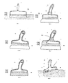
- Fig. 3 shows a schematic longitudinal sectional assembling view of a painting brush according to the invention, similar to the longitudinal view as shown in Fig. 1 , showing the body with a body wall 1 and a longitudinally extending liquid tight cavity 2 in the handle part OA thereof.
- the handle part OA further comprises a handle connection mean, here a threaded protrusion 3 for connection with a mating threading 5B of a handle 5.
- the handle here in form of a solid handle 5, has a through-going hole 7 for receiving e.g. a strap to hang the hand tool from a hook when not in use.
- the wall junction 4 in the tool part OB of the body comprises fastening means 8, e.g. a click/groove locking system, or glue such as epoxy, (not shown) for fastening a tool frame 6C comprising a hair brush 6B.
- Fig. 4 shows a schematic longitudinal side view of a filing knife according to the invention floating in a liquid.
- the handle 5 and a part of the body O merge out of the liquid.
- a part of the body, i.e. the handle part OA and the tool part OB, and the tool, here a blade 6A, are submerged below the surface of the liquid.
- the handle, here a solid handle 5 has a through-going hole 7 for hanging the hand tool from a hook when not in use.
- Fig. 5 shows a schematic longitudinal sectional assembling view of a filing knife according to the invention, similar to the longitudinal view shown in Fig. 1 , showing the body O with a body wall 1 and a longitudinally extending liquid tight cavity 2 in the handle part OA thereof.
- the handle part comprises a snap protrusion 3 for connection with a handle 5 with a mating snap 5B.
- the handle 5 is hollow and has a through-going hole 7 for hanging the hand tool from a hook when not in use.
- the wall junction in the tool part of the body comprises fastening means (not shown) for connecting the body to a blade 6A of a filing knife.
- the handle cavity 5C is preferably liquid tight in order to prevent accumulation of liquid, and thereby avoiding introduction of an unbalanced weight if the handle is submerged into the liquid and liquid penetrates into the cavity. If water has entered into the handle, the handle 5 would not be in an upright position as for the filing knife shown in Fig. 4 , but it would be inclined in skew manner.
- a skew orientation of the floating hand tool can provide a more convenient handling of the hand tool for specific working operations by the hand.
- a skew orientation affects the distribution of mass of the hand tool and shifts the centre of gravity compared to that off the filing knife shown in Fig. 4 .
- the balancing masses can be incorporated into the body's wall and cavit ies, e.g. the volume and/or mass of the cavity can be slightly reduced and the volume and /or mass of the wall junction 4 can be slightly increased in the part of the body opposite to the skew handle. This is illustrated in fig. 7 .
- Fig. 6 shows a schematic longitudinal sectional assembling view of a filing knife according to the invention, similar to the longitudinal view shown in Fig. 1 , showing the body with a longitudinally extending liquid tight cavity 2 in the handle part OA of the body which is integrally connected with the handle 5.
- the handle 5 is hollow and has a through-going hole 7 for receiving e.g. a strap for hanging the hand tool from a hook when not in use.
- This integrated body and handle may comprise compensation of unbalanced mass in form of matched volume of body wall 1, cavity 2, and wall junction, or alternatively using ballasts (not shown).
- the hand tool comprises a tool 6A in form of a blade.
- Fig. 7 shows, in an embodiment, in a similar longitudinal view as shown in Fig. 6 , how the compensation for unbalance of weights on the hand tool around the centre line can be accomplished by reducing the left-hand side 9 volume of the cavity 2 of the body and increasing the left-hand side volume and/or mass 10 of the body wall 1, both in the opposite direction of the skew handle.
- ballast means such as metal objects of suitable shape and sizes could be incorporated into the wall junction of the tool part OB of the body.
- the compensation would be larger, as a solid skew handle introduces a larger inclination of the floating hand tool. It would be within the skills of a person skilled in the art to experimentally arrange masses of the hand tool, e.g. volumes of construction material and cavities, or ballasts to provide the desired orientation of the handle of the floating hand tool.
- Fig. 8 shows a schematic longitudinal sectional assembling view of a filing knife according to the invention, similar to the longitudinal view shown in Fig. 1 , showing the body with a longitudinally extending liquid tight cavity 2 in the handle part OA which body wall 1 is integrally connected with the handle 5 and the wall junction of the tool part OB which is integrally connected with the tool, here a blade 6A.
- the handle here a hollow handle 5, has a through-going hole 7 for hanging the hand tool from a hook when not in use.
- Fig. 9 shows a schematic longitudinal sectional view of a filing knife according to the invention, similar to the longitudinal view shown in Fig. 1 , showing the body with a longitudinally extending liquid tight cavity 2 in the handle part OA which is integrally connected with a cavity 5C in the handle 5.
- the handle here a hollow handle 5, has a through-going hole 7 for hanging the hand tool from a hook when not in use.
- the skew position of the handle is compensated for by ballasts means 11 which establishes an upright position of the handle with respect to the surface of the liquid.
- This hand tool has a tool in form of a blade 6A.
- Fig. 10 shows a schematic longitudinal sectional assembling view of a filing knife according to the invention, similar to the longitudinal view shown in Fig. 1 , showing the body with a longitudinally extending liquid tight cavity in the handle part OA which is integrally connected with a cavity 5C of the handle 5.
- the integrated body and handle is produced in two halves which are joined by a suitable joining technique such as gluing, screwing, soldering by friction, infrared or ultrasonic sound.
- Each of the two halves can be produced by a suitable moulding technique such as injection moulding in a thermo plastic such as polypropylene or acrylonitrile butadiene styrene monomer.
- the tool part OB of the body comprises fixture means and guiding protrusions 13B for facilitating assembling fixture of the blade 6A which may comprise holes 13A for receiving the fixture means.
- Fig. 11 shows a schematic longitudinal sectional assembling view of a painting brush according to the invention, similar to the longitudinal view shown in Fig. 1 , showing the body with a body wall 1 and a longitudinally extending liquid tight cavity 2 integrally connected to a handle with cavity 5C, and a fastening means 8 in the tool part OB for fastening a brush head with hair brush 6B to the body.
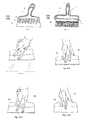
- Fig. 12A-12D shows a schematic longitudinal side view of a filing knife according to the invention, indicating an integrated handle having a skew inclination.
- Fig. 12A shows the index finger and middle finger pointing in a skew direction with respect to the working line of the blade.
- the arrow indicates no presence of a support ridge for this embodiment.
- This skew direction allows an extreme ulnar deviation in the wrist which causes strain to the finger joints and muscles that are stressed. Working over a long time in this position might be inconvenient and might cause damage to hand muscles and joints.
- Fig. 12B shows a schematic longitudinal side view of a filing knife according to the invention, indicating an integrated skew handle with a support ridge 14 to support the thumb while the index finger and middle finger points in a direction substantially perpendicular to the working line of the blade pressing against the body and blade. This position is more convenient because neither muscles nor joints are strained.
- the filing knife further exhibits a finger hole 15.
- Fig. 12C shows a schematic longitudinal side view of a filing knife according to the invention similar to that shown in Fig. 12B but supporting the palm area between the thumb and index finger instead of the thumb. This provides a similar substantial perpendicular direction of the pointing finger to the working line of the blade while pressing against the body and blade.
- Fig. 12D shows a schematic longitudinal side view of a filing knife according to the invention similar to that shown in Fig. 12B supporting the thumb and only the pointing finger. This provides a similar substantial perpendicular direction of the pointing finger to the working line of the blade.
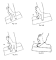
- Figs. 13A-13D show a schematic longitudinal side view of a filing knife according to the invention similar to that shown in Fig. 12A . Different position of the hand and fingers with respect to the finger hole 15 are shown. These alternative positions of the hand and fingers are convenient because different working position can be used during a working session. This changes the load on different individual muscles and joints.
Landscapes
- Engineering & Computer Science (AREA)
- Architecture (AREA)
- Civil Engineering (AREA)
- Structural Engineering (AREA)
- Mechanical Engineering (AREA)
- Prostheses (AREA)
- Food-Manufacturing Devices (AREA)
- Brushes (AREA)
Abstract
A buoyant hand tool body for joining a handle (5) and a tool (6) of a hand tool, the body (O) comprising a handle part (OA) and a tool part (OB), and being adapted so that the body floats in a liquid with the handle part above the tool part; a handle; a tool; a hand tool, a tool kit; and a method of producing a floatable hand tool.
Description
- The present invention relates to a buoyant hand tool body, a handle, a tool, a floatable hand tool, a hand tool kit, and a method of producing same.
- Conventional hand tools comprise a handle and a tool connected to the handle.
- The handle is formed and adapted for holding and operating the tool by hand. The handle of the tool can be gripped directly by a hand, or indirectly through a hand tool extension. Handles can be made solid, hollow, or a combination thereof, and they may consist of a suitable material such as wood, plastic, metal e.g. aluminium or steel, etc.
- The tool is formed and adapted for its intended application, e.g. a blade for padding, or a brush for painting. Tools can be made solid, hollow, or a combination thereof, and they may consist of a suitable material such as wood, plastic, metal e.g. steel, rubber, brush hair, etc.
- Whether a hand tool floats or sinks in a liquid such as water, organic solvent, or cleaning liquid, etc. depends on the density of the hand tool compared to the density of the liquid.
- A floatable hand tool can be picked up from a liquid, e.g. if accidentally dropped while working above the liquid, e.g. when working on a boat or bridge, or if intentionally been placed therein for cleaning. If picked up by hand, however, the hand might get into contact with the liquid which might be hazardous and undesirable.
- In
GB 1,118,905 - In
US 7,475,620 (CHEN) 13-01-2009 there is disclosed a hand tool comprising a handle, a shank, and a fluorescent layer coated on the outer periphery of the handle. The handle has an enclosed chamber, an L-shaped or T-shaped recess in the end thereof wherein an end of the shank is being fixed. In the other end of the handle, a hole is defined which hole is being in communication with the chamber and is being sealed with a bolt. The chamber can be filled with sand through the hole for increasing its weight so that the hand tool performs like a conventional hand tool. - Without being bound by theory (see e.g. "Fluid Mechanics" in MSN Encarta 2009-03-25) the floatability of the hand tool in a liquid is determined by the density of the hand tool compared to the density of the liquid. The density of the hand tool is the mass per volume of the hand tool comprising mass of handle, mass of body, mass of tool, and optional mass of residues of working material. If the density of the hand tool is smaller than the density of the liquid, the hand tool floats. If the density of the hand tool is larger than the density of the liquid, the hand tool sinks. Thus, floatability of the hand tool can be ensured by controlling the density of the hand tool. However, floatability does not ensure an orientation of the hand tool so that the hand tool can be picked up from a liquid by hand without the hand getting into contact with the liquid.
- When placed into the liquid, e.g. for cleaning of residues of working material, the hand tool displaces a volume of liquid the weight of which equals the weight of the hand tool (Archimedes principles). Above the emerging portion of the hand tool there is a barometric pressure. Below the submerging portion of the hand tool there is a hydrostatic pressure the value of which depends on the density of the liquid and the depth below the surface. The difference between the barometric pressure on the hand tool and the hydrostatic pressure on the hand tool defines the buoyant force exerted by the liquid on the hand tool. At equilibrium the buoyant force equals the weight of the hand tool, i.e. the gravitational force acting on the mass of the hand tool. The buoyant force has a direction opposite to that of gravitation. Its magnitude equals the weight of the displaced liquid. Its line of action is through the centre of mass of the displaced volume of liquid which has been replaced by the submerged hand tool.
- Depending on the distribution of the mass through out the hand tool, the weight of volume elements of the hand tool differs. To a first approximation assuming parallel gravitational forces and a rigid hand tool, the resultant weight of all masses of the different volume elements of the hand tool is the weight acting on the total mass located in the centre of gravity G of the hand tool. For a small hand tool the centre of gravity corresponds to the centre of mass of the hand tool. For a constant distribution of masses in the hand tool over time, the centre of gravity remains constant. However, if the hand tool looses mass, e.g. looses residue material in a cleaning process, the centre of gravity might change.
- Similarly, to a first approximation, the resultant buoyant force exerted on the hand tool by the liquid is the buoyant force acting on the centre of buoyancy B of the volume of liquid which has been replaced by the submerged portion of the hand tool. The location of the centre of buoyancy B can be estimated as the centre of mass of the displaced liquid having the shape and volume of the submerged portion of the hand tool.
- In equilibrium, when a clean hand tool is floating in a liquid, the centre of gravity G and the centre of buoyancy B are aligned on a common line of action. However, if the hand tool gets an extra mass e.g. residues placed off the common line of action, the centre of mass of the hand tool is shifted. There is no common line of action for the gravitational force and the buoyant force. As the shape and volume of the displaced liquid is unchanged, the centre of buoyancy B is unchanged while the centre of gravity G is shifted off the common line of action. Because the gravitational force and the buoyant force act on different centres there is a torque on the hand tool. In order to establish equilibrium the hand tool rotates. Depending on the shape and volume of the hand tool and the friction against the liquid of the submerged part of the hand tool, this rotation might cause the centre of buoyancy to shift. Consequently the torque is reduced. The rotation continues, optionally through dampened oscillation, until a common line of action for the gravitation and the buoyant forces is obtained and the floating hand tool assumes an inclined stable orientation with respect to an upright position.
- A similar description can be given for a hand tool floating stably with a given inclination in a liquid which hand tool is tilted by an external force e.g. a push. Consequently, the hand tool experiences a torque which makes the hand tool rotate until equilibrium is reached. During this rotation, however, the tool handle may become whole or partially wetted by the liquid depending on the positions of G and B.
- By analogy to vessel construction (see e.g. Maritime Dictionary 2009-03-25), there is an angle from the upright position of the hand tool at which the maximum inclination can occur before the hand tool becomes unstable and might capsize by an external force, the so-called angle of loll. This occurs when the so-called metacentre M and the centre of gravity G coincide and the righting lever is zero. The metacentre M is the intersection of the action line of the centre of buoyancy B for an inclined hand tool with respect to the action line of a non-inclined hand tool. At the angle of loll, the lever arm of the torque is zero, or close to zero. However, the centre of gravity G is on the same line of action as the centre of buoyancy B but located above it. If the centre of gravity G gets above the metacentre M, the hand tool is unstable and the hand tool might capsize.
- The metacentre M is primarily determined by the shape of the submerged hand tool. A narrow width of the hand tool provides a low metacentre M. A broad width of the hand tool provides a high metacentre M. A high metacentre allows a high centre of gravity G, e.g. the mass of the handle can be larger, as for a solid handle, without the hand tool capsizing. The distance between the centre of gravity G and the metacentre M, the so-called metacentric height GM, is a measure of the stability of the hand tool. It is important because the force righting the inclining tool is proportional to the metacentric height GM times the sine of the angle of inclination. For a negative GM, the hand tool is unstable.
- The position of the centre of gravity G can be either above, below, or coincide with the centre of buoyancy B. If B is higher than G, inclining the hand tool moves B such that the gravitational force and the buoyant force provide a torque which seeks to align the two centres. The greater the distance, the more stable the hand tool. Depending on shape of the body and frictional forces between the submerged hand tool and the liquid, the rotation may be a dampened oscillation about the centre line wherein the torque changes direction and magnitude until the oscillation stops. If G is higher than B, an inclination of the hand tool can still be stable. Depending on the shape, volume and friction of the submerged hand tool, e.g. its length, width, depth, stabilizing fins, etc., the shift of the centre of buoyancy B may catch up with the shift of centre of gravity G. Outside these limits the hand tool will become unstable. If G and B coincide, there is no torque.
- It turns out that by controlling the location of the centre of gravity G, the centre of buoyancy B, the metacentre M, the orientation and stability of the floating hand tool can be controlled.
- Hand tools may be designed for use that does not overstretch muscles and joints. An ergonomic hand tool is adapted and shaped for muscles and joints to operate in their middle position, the so-called neutral position.
- In
US 5,615,445 (KELSAY ET AL.) 01-04-1997 there is disclosed a taping knife including a blade with an elongated handle secured to the blade. The handle includes a hollow inner member formed from adjoining member halves which have an inner structural support network of ribs. The handle component parts sealably interlock. The watertight seals prevent water to leak into the handle's hollow cavities thereby ensuring the weight advantage of the hollow structure. - In
WO 00/37221 A (ANZA AB) 29-06-2000 - Without being bound by theory, ergonomic working operations for the human body comprise motions of muscles and joints which are not overstretched. This can be accomplished by operating muscles and joints in their middle position, or so-called neutral position.
- For muscles, this position provides the optimum opportunity to develop power without being overstretched.
- For joints, the middle position provides the largest thickness of the joint cartilage whereby optimum protection of the joint is achieved. If a joint is frequently brought into its extreme positions in which a force or power is applied, the joint is stretched in a position where it is most vulnerable. The joint cartilage is thin, and it is eventually worn down. Degenerative arthritis can be developed. The cartilage degenerates and looses its elastic properties.
- Moreover, repeated stretching in extreme positions can develop less elastic ligaments that links two bones together at a joint so that the ligaments no longer provides a protective tissue for an otherwise stable joint.
- Consequently, ergonomic hand tools are designed to avoid or reduce stretching of joints in extreme positions.
- In an aspect, it is the object of the present invention to provide a hand tool which can be picked up from a liquid by hand without the hand getting into contact with the liquid.
- In another aspect, it is the object the present invention to provide a hand tool which allows an improved ergonomic working position.
- In still another aspect, it is the object the present invention to provide a method of providing such a hand tool.
- Further aspects of the present invention appear elsewhere.
- In an aspect, these objects are fulfilled according to the invention by providing a buoyant hand tool body for joining a handle and a tool of a hand tool, the body comprising a handle part and a tool part, and being adapted so that the body floats in a liquid with the handle part above the tool part, whereby a floatable hand tool can be provided which can be picked up from a liquid by hand without the hand getting into contact with the liquid.
- A floatable hand tool has a density less than the density of the liquid in which it is floating. The density of the hand tool can be determined by calculation as the average density of densities of volume elements making up the hand tool. The density can be determined by weighing the hand tool and by measuring its volume. The volume can be measured by the displaced volume of water when submerged in the liquid. Floatability of a hand tool can be determined by experiment, observing whether the hand tool floats or sinks when submerged in the liquid.
- For a buoyant hand tool body to float in a liquid with the handle part above the tool part, the volume, shape, distribution of mass, and friction of the body is being arranged so that the body floats in the liquid in an upright position, or with an inclination, whereby a given orientation and stability of the hand tool when floating in the liquid is achieved. It is within the skills of a skilled person to select and arrange the parameters of volume, shape, distribution of mass, and friction of the body and experimentally verify whether the hand tool has achieved the desired floatability, orientation, and stability, e.g. as described in the following.
- Generally, the volume of the body, or its size, is selected to accommodate various means for ensuring its functionality. These various means comprises means for ensuring the floatability, orientation, and stability of the hand tool, and means for connecting the body to the handle and to the tool, respectively. Means for ensuring the floatability, orientation, and stability of the hand tool comprise cavities and construction materials arranged to ensure strength, form, and mass distribution of the hand tool body. Hand tools are usually provided in different sizes depending on their application and physical capabilities of the user, e.g. whether design for handling by one hand, two hands or by an extension tool.
- The shape of the body is selected to ensure its functionality. For example, a filing knife must be able to approach the surface of the object for which it is intended to work on. A body having a bulky shape might not be suited for this purpose whereas a narrow body conically tapering towards the tool might be suited. Also, a filing knife comprises an elongated body form in order to connect to a blade of suitable size to carrying or padding the material for which it is used, e.g. by one hand or by two hands.
- Moreover, the shape of the body, which is submerged in the liquid, determines the floating stability of the body and subsequently the floating stability of the hand tool. Generally, subject to constrain on its functionality, the shape of the body is selected so that the floating hand tool, i.e. the body assembled to the handle and tool, has a metacentre M located high in or above the body when is floating in the liquid. This allows for a high centre of gravity G while G is less that or equal to M. This ensures stability and prevents capsizing of the floating hand tool. That is, more mass can be allocated high in the hand tool, e.g. in the handle, than for a hand tool with low M.
- For a longitudinally extended body, like a conventional filing knife or broad paint brush, a high metacentre M can be achieved by selecting a shape exhibiting a suitably large transverse width/height ratio W/H of the longitudinal body. A skilled person is able to experiment and select a transverse width/height ratio W/H within wide limits.
- A lower limit of the width/height ratio depends on the minimum dimensions and the mechanical properties of the material used, e.g. a sufficient mechanical strength for the connection means connecting the handle and tool, respectively, to the body. To achieve this, a relatively large minimum width of the body may be required. A skilled person would know how to select, e.g. by experiment, the dimensions of the material he intend to use in order to provide sufficient mechanical strength.
- An upper limit of the width/height ratio depends on the application of the tool, e.g. it ability to approach a surface of an object to be worked on, which requires that the hand tool body is not too bulky. It is within the skills of a skilled person to select a shape within these extremes of lower and upper limits.
- For a non-limiting intuitive explanation of how a high metacentre M can provide stability of the floating body, one can imagine the stability of a floating plate which has a shape comprising large lateral dimensions and a small height. Such a floating body has a large width/height ratio W/H and it is very difficult, or even impossible, to capsize it, i.e. turn it over when it is floating in the surface of a liquid.
- The distribution of mass is arranged to provide the location of the centre of gravity G. In an embodiment the centre of gravity G is below or equal to the metacentre M when floating in the liquid which ensures stability of a given orientation of the handle of the floating hand tool. Thus, selecting a shape providing a high metacentre M allows for a high centre of gravity G while maintaining a high stability.
- In an embodiment the handle part comprises a material having a density less than the density of the liquid, and the tool part comprises a material having a density larger than the density of the liquid whereby the body can provide a desired orientation of the handle and tool.
- In an embodiment having a high M, the mass is arranged so that a relative large mass is located in the handle part of the body. This is advantageous for hand tool designs that require a strong connection between the handle and the hand tool body and for which purpose high density materials such as metals e.g. steel such as stainless steel, or tempered steel, can be used.
- In another embodiment, the mass is arranged so that a relative large mass is located in handle itself. This could be advantageous for an ergonomic hand tool requiring a small torque between the weight on the hand and the weight on the hand tool, whereby an extreme ulnar deviation of the hand joint, which otherwise would be required in order to operate a hand tool with a large torque, can be reduced.
- Generally, the distribution of mass allows for alternative designs of the body with respect to the number, size and distribution of cavities and construction materials used. In an embodiment this is achieved by a body wherein the material is contained in at least one cavity. For a symmetric hand tool, the construction materials and cavities are symmetrically arranged around the geometric symmetry line. Therefore, the distribution of mass follows the geometric distribution of the construction materials and cavities whereby the action line of the centre of gravity and the symmetry line of the hand tool coincide. For an asymmetric hand tool having non-symmetrically arranged construction material and cavities, however, such as ergonomic hand tools having a skew handle, the distribution of mass is not symmetrical. To ensure a given orientation of the handle, the construction material and cavities of the hand tool body are arranged so that the distribution of mass provides the desired action line for the centre of gravity G. This can be obtained by selecting a distribution of cavity volumes, cavity walls, and construction materials for cavity wall so that the mass distribution provides a desired centre of gravity G. It is within the skills of a skilled person to arrange cavities and cavity materials, e.g. using materials having densities larger and lower than that of the liquid, to provide the desired centre of gravity G, either by calculation, experiment, or both.
- Alternatively, or additionally, the hand tool, e.g. the handle and/or the body, may comprise ballasts that are arranged for providing the distribution of mass that provides a desired centre of gravity G. Particularly for painting brushes, the ballast may comprise an internal keel-like material in form of suitable material, e.g. a plastic, glue such as epoxy, a steel rod or steel balls, contained in cavities.
- In an embodiment, a body comprises ballast fixation means for receiving ballasts whereby it is obtained that the same body design can be used for both symmetric handles and ergonomic asymmetric handles. In case of an ergonomic asymmetric handle, the body may comprise ballasts to ensure the desired location of the centre of gravity G. For a symmetric handle ballasts might not be necessary.
- The rotation of the floating body is primarily determined by the torque between the centre of gravity G and the centre of buoyancy B. However, the rotation of the body is further determined by the friction between the body and the liquid. For a low friction, the body might easily rotate compared to a high friction. Friction depends on the shape of the body and the viscosity of the liquid (Stokes law) and it can be modified by modifying the shape of the body by introducing stabilising means such as fins, or similar, e.g. protruding edges of mounting frames for brush hair. The micro structure of the surface of the body might also affect the friction and can be modified by applying coatings to the outer body surface. Suitable coatings comprise colour coatings, e.g. applied in a colour code according to the size of the hand tool, and/or its use in organic/inorganic liquids.
- To ensure floating, the density of the hand tool including all parts and optional residues must be less than the density of the liquid. In case of water, e.g. pure water with out additives, the density is close to 1 g/l at room temperature and pressure. In case of an organic solvent such as mineral turpentine (petroleum-based turpentine 0.85 g/I), or an alcohol such as ethanol (0.79 g/I), the density is less than 1, and the design and materials for the body must be chosen accordingly to ensure floatability. The hand tool body can be made solid, hollow, or a combination thereof. It may comprise a suitable material such as a gas, a gas mixture, air; a wood, a plastic, a foam such as polyurethane foam, a glue such as epoxy, metal e.g. aluminium, steel such as stainless steel, etc.
- Preferred embodiments are defined in the subclaims.
- In another aspect, these objects are fulfilled according to the invention by providing a handle for a hand tool wherein the handle comprises at least one support ridge; e.g. for supporting the thumb, or supporting the palm area between the thumb and index finger instead of the thumb, whereby extreme ulnar deviation can be avoided or reduced, i.e. an extreme position of the hand in which the wrist bends towards the little finger, and whereby repetitive strain injuries of the joints can be avoided.
- In an embodiment, the ridge is being arranged in or at the region where the handle is connecting to the tool body, whereby the index finger (demonstratus) or the middle finger (impudicus) assumes a direction substantially perpendicular to the line of contact with the object on which the hand tool is working, and a direction along a line extending the muscles of the forearm and the wrist, i.e. a position where they can develop the largest force for the work.
- Hand tools having skew handles and comprising a support ridge are particularly preferred. A relative high mass can be arranged in the handle part of the hand tool, it being located in the skew handle at the opposite side of the ridge, whereby the same materials can be used for the masses balancing out the weight of the skew handle and the weight of the ridge, and little or no ballast would be needed to ensure the orientation of the floating hand tool.
- When working with hand tools, it is an advantage to change position of the hand and avoid applying a static grip of the hand tool in the same working position over a longer period of time.
- In an embodiment, the hand tool body comprises at least one through-going finger hole, preferably being located in a region laterally displaced to the side where the handle is inclined. Preferably the finger hole is being adapted to receive either of the fingers, not the thumb. Preferably the finger hole is adapted to receive the index finger or the middle finger, whereby a particularly convenient grip can be obtained. However, the finger hole might receive e.g. the ring finger or the little finger as well. The hand tool can be carried in a convenient way by using the index finger when resting the hand between working sessions.
- The hand tool can be adapted for being operated with the right hand, the left hand, or both, optionally via a hand tool extension. Typically, two hands are used when working with a broad filing knife, e.g. padding a larger wall area. Typically, a hand tool extension is used when working with a paint brush, e.g. painting a high wall. Handles can be made solid, hollow, or a combination thereof. They may comprise a suitable material such as wood, plastic, foam such as polyurethane foam, metal, e.g. aluminium, steel such as stainless steel, etc.
- In still another aspect, this object is fulfilled by provide a method of producing a floatable hand tool comprising a handle and a tool, the method comprising: (i) providing a hand tool body comprising a handle part and a tool part, the volume, shape, distribution of mass, and friction of the body being arranged so that the body floats in a liquid with the handle part above the tool part; (ii) determined the location of the metacentre M; and (iii) optionally modify the volume, shape, distribution of mass and/or friction of the body to provide a centre of gravity G lower than or equal to the metacentre M, whereby it is ensured that a hand tool which can be picked up from a liquid by hand without the hand getting into contact with the liquid can be produced.
- In an embodiment, the centre of gravity G is lower than the centre of buoyancy B. In another embodiment, the centre of gravity G is located in the lower part of the body. In still another embodiment, the centre of gravity G is located in the tool part of the hand tool.
- In a further aspect, these objects are fulfilled by providing a tool for a floatable hand tool according to the invention comprising a hand tool body wherein the tool is integrally joining the hand tool body whereby specific hand tools can be produced, e.g. a rubber based tool in which the tool part and the body can be produced in a one-step casting operation. Generally, the tool can be made solid, hollow, or a combination thereof. It comprises a suitable material for its intended application, such as wood, plastic, metal e.g. steel such as stainless steel, rubber, brush hair, etc. In a preferred embodiment, the material of the tool is selected from the group consisting of plastics, steel such as stainless steel, tempered steel, rubber, and brush hair, or a combination thereof. A preferable hand tool is a filing knife or paint brush.
- In still a further aspect, these objects are fulfilled by providing a floatable hand tool comprising a handle, a tool, and a buoyant body according to the invention whereby the advantages of the individual parts: handle, tool and body can be utilized alone, or in combination.
- In still a further aspect, these objects are fulfilled by providing a hand tool kit comprising the handle, the tool, and the body according to the invention where by the individual parts of the kit can be optimized for its specific application, and the user can combined the parts as desired.
- In an embodiment, the volume, shape, distribution of mass, and friction of the body being arranged so that the body floats in the liquid in an upright position, or with an inclination whereby it is obtained that a the handle can be arranged so that it has desired orientation which can easily be gripped by a hand.
- In an embodiment, the handle part comprises a material having a density less than the density of the liquid, and the tool part comprises a material having a density larger than the density of the liquid whereby the buoyancy of the body is ensured.
- In an embodiment, the material is contained in at least one cavity whereby it is obtained that the material of the cavity can be selected according to the density providing a desired distribution of mass. More cavities can be used whereby a sufficient mechanical strength can be obtained for a light hand tool.
- In an embodiment, the material comprises a material selected from a gas, a gas mixture such as air; a wood; a plastic such as high density and low density plastics; a foam such as polyurethane foam; and a metal such as steel such as stainless steel whereby materials of low density, high density, or combinations thereof, and materials having different properties, e.g. materials being compatible with organic solvents, can be selected. It is with the skills of a skilled person to select combinations of these materials with respect to the function and intended use of the hand tool.
- In an embodiment, the centre of gravity G is below or equal to the metacentre M when floating in the liquid whereby floating stability is ensured.
- In an embodiment, the handle part or the handle comprising a support ridge for supporting of a thumb whereby an ergonomic hand tool ensuring a neutral position of muscles and joints in the hand and wrist can be obtained. The ergonomic hand tool provides better results in form of more precise work, nicer looking finishes, and longer working sessions without introducing damages to the muscles and joints.
- In an embodiment, the body comprises at least one through-going finger hole whereby alternative ergonomic grips can be obtained.
- A handle for a hand tool comprising a hand tool body wherein the handle comprises at least one support ridge, e.g. for supporting of a thumb, or supporting the palm area between the thumb and index finger instead of the thumb, the support ridge preferably being arranged in or at the region where the handle is connectable to the body.
- In an embodiment, the handle is integrally connecting to the body whereby a simplified method of manufacture can be obtained, said method comprising preparing two half-parts of the integral handle and body which can be assembled with the tool in a one-step operation.
- In an embodiment, the body comprises a through-going finger hole ensuring that a particularly convenient ergonomic hand tool with integral handle and body can be manufacture in two half-parts and assembled in a one-step operation.
- In the present context, it is intended that the term handle part of the body designates a part of the body facing the side of the hand tool from where the handle is gripped. The actual connection between the body and handle can be at any suitable location on the body. In use, the handle part is the upper part of the floating body. Similarly the term tool part of the body designates a part of the body facing the side of the hand tool where the tool is operating. In use, the tool part is the lower part of the floating body. In an embodiment, the actual connection point for the handle can be in the tool part. In the present context, it is intended that the term weight designates the physical term force for the gravitational force acting on a mass of an object. Weight should not be confused with the term mass
-
Fig. 1 shows a schematic longitudinal view of an embodiment of a hand tool body according to the invention; -
Fig. 1A and Fig. 1B show schematic cross sectional views along the line A-A inFig. 1 for an upright and an inclined position, respectively; -
Fig. 2 shows a schematic longitudinal sectional view of a filing knife according to the invention; -
Figs. 3 and11 show schematic longitudinal sectional assembling view of a painting brush according to the invention; -
Fig. 4 shows a schematic longitudinal side view of a filing knife according to the invention floating in a liquid; -
Figs. 5-7 and10 show schematic longitudinal sectional assembling views of filing knives according to the invention; -
Fig. 9 shows a schematic longitudinal sectional view of a filing knife according to the invention balanced to exhibit a vertical orientation of the handle when floating in a liquid; -
Figs. 12A-12D show a schematic longitudinal side views of various hand positions when operating a filing knife with a support ridge according to the invention; and -
Figs. 13A-13D show a schematic longitudinal side views of various hand positions when operating a filing knife with a finger hole according to the invention. - In Table 1 there is presented element references used on the figures.
Table 1 Element
reference signElement O body OA handle part OB tool part OC handle fixation means L liquid line w body width H body height G centre of gravity B centre of buoyancy B1 centre of buoyancy for upright body B2 centre of buoyancy for inclined body M metacentre - transverse M□ metacentre - longitudinal 1 body wall 2 cavity 3 threaded protrusion 4 wall junction 4A ballast 5 handle 5A lateral protrusion 5B thread 5C cavity 6 tool 6A blade 6B hair brush 6C frame 6D tubular through-going channel in body 7 through-going hole in handle 8 fastening means 9 left-hand side of cavity 10 left-hand side of body wall 11 ballast 12 fixture projections 13A fixture hole 13B fixture hole projection 14 support ridge 15 finger hole -
Fig. 1 shows a schematic longitudinal view of an embodiment of a hand tool body O according to the invention floating in a liquid L, said body having a handle part OA with handle fixation means OC and a tool part OB. Further details are shown inFig. 1A and Fig. 1B . -
Fig. 1A and Fig. 1B show schematic cross-sectional views along the line A-A inFig. 1 for an upright position and an inclined position, respectively. The line B-B indicates the longitudinal view shown inFig. 1 . The body comprises a handle part OA and a tool part OB. The handle part OA comprises abody wall 1, a liquid tight cavity 2 (reference shown inFig. 1B ), and a handle fixation means OC for connecting a handle. The tool part OB comprises a portion of the liquidtight cavity 2 and awall junction 4 which is tapered towards to lower part. The lower part can be adapted for mounting a tool such as a blade of a filing knife. A measure of the shape of the body can be obtained by the ratio W/H of the width W divided the height H of the body. This is a coarse form parameter of the body form. It can be calibrated experimentally for various forms of the body. The transverse distribution of the mass of thecavity 2 and thewall junction 4 ensures a low centre of gravity G. Here, G is shown below the centre of buoyancy B1 of the displaced liquid for the upright position of the body. In the inclined position, the centre of buoyancy B2 is above the centre of gravity G. It turns out that for a relative narrow body compared to a broad one, e.g. a W/H ratio smaller than 0.6 depending on the cavity and material used, the transverse metacentre M is low. The transverse stability measured by the distance GM is therefore lower than for a broad body, e.g. a W/H ratio larger than 0.6. However, since the distance GM is relative large, the transverse stability is relative high in spite of M being low. Once assembled with handle and tool the metacentre M of the transverse stability can be determined experimentally by measuring the righting lever, i.e. the torque of gravitational force acting on G and the buoyant forces acting in opposite direction on B, versus the angle of inclination. - Once assembled with handle and tool the metacentre M' not shown) of the longitudinal stability can be determined. It turns out that for a relative long body compared to a narrow one, the metacentre M' is high. The longitudinal stability measured by the distance GM' is therefore high. It should be noted that M and M' generally differ for a longitudinal ly shaped body. They may coincide for a symmetrically shaped body, e.g. a spherically shaped body.
-
Fig. 2 shows a schematic longitudinal sectional view of a paint brush according to the invention, similar to the longitudinal view of the body shown inFig. 1 , showing the body having a longitudinally extending liquidtight cavity 2 in the handle part OA thereof and a handle fixation means OC, here a through-goingtubular channel 6D for receiving ahandle 5. The handle, here a solid handle, 5 comprises a fixation means at its distal end, here a distallateral protrusion 5A for connecting thehandle 5 to the body via the tool part OB of the body. The wall junction of the tool part OB of the body comprises handle fixation means, here comprising an extension of the tubular through-goingchannel 6D in both the handle part and the tool part of the body. The lateral protrusions of thedistal handle end 5A are fixed to the tool part OB comprising aframe 6C for carrying hair brushes 6B. Thecavity 2 may comprises more chambers, e.g. air-filled chambers, with walls in a grid pattern for increasing the strength of the body. -
Fig. 3 shows a schematic longitudinal sectional assembling view of a painting brush according to the invention, similar to the longitudinal view as shown inFig. 1 , showing the body with abody wall 1 and a longitudinally extending liquidtight cavity 2 in the handle part OA thereof. The handle part OA further comprises a handle connection mean, here a threadedprotrusion 3 for connection with a mating threading 5B of ahandle 5. The handle, here in form of asolid handle 5, has a through-goinghole 7 for receiving e.g. a strap to hang the hand tool from a hook when not in use. Thewall junction 4 in the tool part OB of the body comprises fastening means 8, e.g. a click/groove locking system, or glue such as epoxy, (not shown) for fastening atool frame 6C comprising a hair brush 6B. -
Fig. 4 shows a schematic longitudinal side view of a filing knife according to the invention floating in a liquid. Thehandle 5 and a part of the body O merge out of the liquid. A part of the body, i.e. the handle part OA and the tool part OB, and the tool, here ablade 6A, are submerged below the surface of the liquid. The handle, here asolid handle 5, has a through-goinghole 7 for hanging the hand tool from a hook when not in use. -
Fig. 5 shows a schematic longitudinal sectional assembling view of a filing knife according to the invention, similar to the longitudinal view shown inFig. 1 , showing the body O with abody wall 1 and a longitudinally extending liquidtight cavity 2 in the handle part OA thereof. The handle part comprises asnap protrusion 3 for connection with ahandle 5 with amating snap 5B. Thehandle 5 is hollow and has a through-goinghole 7 for hanging the hand tool from a hook when not in use. The wall junction in the tool part of the body comprises fastening means (not shown) for connecting the body to ablade 6A of a filing knife. Thehandle cavity 5C is preferably liquid tight in order to prevent accumulation of liquid, and thereby avoiding introduction of an unbalanced weight if the handle is submerged into the liquid and liquid penetrates into the cavity. If water has entered into the handle, thehandle 5 would not be in an upright position as for the filing knife shown inFig. 4 , but it would be inclined in skew manner. - Generally, a skew orientation of the floating hand tool can provide a more convenient handling of the hand tool for specific working operations by the hand. However, a skew orientation affects the distribution of mass of the hand tool and shifts the centre of gravity compared to that off the filing knife shown in
Fig. 4 . To compensate for this unbalance of weights on the hand tool around the centre line, the balancing masses can be incorporated into the body's wall and cavit ies, e.g. the volume and/or mass of the cavity can be slightly reduced and the volume and /or mass of thewall junction 4 can be slightly increased in the part of the body opposite to the skew handle. This is illustrated infig. 7 . -
Fig. 6 shows a schematic longitudinal sectional assembling view of a filing knife according to the invention, similar to the longitudinal view shown inFig. 1 , showing the body with a longitudinally extending liquidtight cavity 2 in the handle part OA of the body which is integrally connected with thehandle 5. Thehandle 5 is hollow and has a through-goinghole 7 for receiving e.g. a strap for hanging the hand tool from a hook when not in use. This integrated body and handle may comprise compensation of unbalanced mass in form of matched volume ofbody wall 1,cavity 2, and wall junction, or alternatively using ballasts (not shown). The hand tool comprises atool 6A in form of a blade. -
Fig. 7 shows, in an embodiment, in a similar longitudinal view as shown inFig. 6 , how the compensation for unbalance of weights on the hand tool around the centre line can be accomplished by reducing the left-hand side 9 volume of thecavity 2 of the body and increasing the left-hand side volume and/or mass 10 of thebody wall 1, both in the opposite direction of the skew handle. Alternatively, ballast means such as metal objects of suitable shape and sizes could be incorporated into the wall junction of the tool part OB of the body. For a solid handle (not shown) instead of thehollow handle 5C, the compensation would be larger, as a solid skew handle introduces a larger inclination of the floating hand tool. It would be within the skills of a person skilled in the art to experimentally arrange masses of the hand tool, e.g. volumes of construction material and cavities, or ballasts to provide the desired orientation of the handle of the floating hand tool. -
Fig. 8 shows a schematic longitudinal sectional assembling view of a filing knife according to the invention, similar to the longitudinal view shown inFig. 1 , showing the body with a longitudinally extending liquidtight cavity 2 in the handle part OA whichbody wall 1 is integrally connected with thehandle 5 and the wall junction of the tool part OB which is integrally connected with the tool, here ablade 6A. The handle, here ahollow handle 5, has a through-goinghole 7 for hanging the hand tool from a hook when not in use. -
Fig. 9 shows a schematic longitudinal sectional view of a filing knife according to the invention, similar to the longitudinal view shown inFig. 1 , showing the body with a longitudinally extending liquidtight cavity 2 in the handle part OA which is integrally connected with acavity 5C in thehandle 5. The handle, here ahollow handle 5, has a through-goinghole 7 for hanging the hand tool from a hook when not in use. The skew position of the handle is compensated for by ballasts means 11 which establishes an upright position of the handle with respect to the surface of the liquid. This hand tool has a tool in form of ablade 6A. -
Fig. 10 shows a schematic longitudinal sectional assembling view of a filing knife according to the invention, similar to the longitudinal view shown inFig. 1 , showing the body with a longitudinally extending liquid tight cavity in the handle part OA which is integrally connected with acavity 5C of thehandle 5. The integrated body and handle is produced in two halves which are joined by a suitable joining technique such as gluing, screwing, soldering by friction, infrared or ultrasonic sound. Each of the two halves can be produced by a suitable moulding technique such as injection moulding in a thermo plastic such as polypropylene or acrylonitrile butadiene styrene monomer. The tool part OB of the body comprises fixture means and guidingprotrusions 13B for facilitating assembling fixture of theblade 6A which may comprise holes 13A for receiving the fixture means. -
Fig. 11 shows a schematic longitudinal sectional assembling view of a painting brush according to the invention, similar to the longitudinal view shown inFig. 1 , showing the body with abody wall 1 and a longitudinally extending liquidtight cavity 2 integrally connected to a handle withcavity 5C, and a fastening means 8 in the tool part OB for fastening a brush head with hair brush 6B to the body. -
Fig. 12A-12D shows a schematic longitudinal side view of a filing knife according to the invention, indicating an integrated handle having a skew inclination. -
Fig. 12A shows the index finger and middle finger pointing in a skew direction with respect to the working line of the blade. The arrow indicates no presence of a support ridge for this embodiment. This skew direction allows an extreme ulnar deviation in the wrist which causes strain to the finger joints and muscles that are stressed. Working over a long time in this position might be inconvenient and might cause damage to hand muscles and joints. -
Fig. 12B shows a schematic longitudinal side view of a filing knife according to the invention, indicating an integrated skew handle with asupport ridge 14 to support the thumb while the index finger and middle finger points in a direction substantially perpendicular to the working line of the blade pressing against the body and blade. This position is more convenient because neither muscles nor joints are strained. The filing knife further exhibits afinger hole 15. -
Fig. 12C shows a schematic longitudinal side view of a filing knife according to the invention similar to that shown inFig. 12B but supporting the palm area between the thumb and index finger instead of the thumb. This provides a similar substantial perpendicular direction of the pointing finger to the working line of the blade while pressing against the body and blade. -
Fig. 12D shows a schematic longitudinal side view of a filing knife according to the invention similar to that shown inFig. 12B supporting the thumb and only the pointing finger. This provides a similar substantial perpendicular direction of the pointing finger to the working line of the blade. -
Figs. 13A-13D show a schematic longitudinal side view of a filing knife according to the invention similar to that shown inFig. 12A . Different position of the hand and fingers with respect to thefinger hole 15 are shown. These alternative positions of the hand and fingers are convenient because different working position can be used during a working session. This changes the load on different individual muscles and joints.
Claims (15)
- A buoyant hand tool body for joining a handle and a tool of a hand tool, the body (O) comprising a handle part (OA) and a tool part (OB), and being adapted so that the body floats in a liquid with the handle part above the tool part.
- The body according to claim 1 wherein the volume, shape, distribution of mass, and friction of the body being arranged so that the body floats in the liquid in an upright position, or with an inclination.
- The body according to claims 1-2 wherein handle part (OA) comprises a material having a density less than the density of the liquid, and the tool part (OB) comprises a material having a density larger than the density of the liquid.
- The body according to claims 1-3 wherein the material is contained in at least one cavity (2).
- The body according to claims 1-4 wherein the material comprises a material selected from a gas, a gas mixture, air; a wood; a plastic; a foam; a glue; or a steel.
- The body according to claims 1-5 wherein the centre of gravity G is below or equal to the metacentre M when floating in the liquid.
- The body according to claims 1-6 wherein the handle part (OA) or the handle (5) comprising at least one support ridge (14).
- The body according to claims 1-7 wherein the body comprises at least one through-going finger hole (15).
- A handle for a hand tool comprising a hand tool body wherein the handle comprises at least one support ridge (14) for supporting of a thumb, the support ridge being arranged in or at the region where the handle is connectable to the body.
- The handle according to claim 9 wherein the handle is integrally connecting to the body.
- The handle according to claims 9 and 10 wherein the body comprises a through-going finger hole (15).
- A tool for a hand tool comprising a hand tool body according to anyone of claims 1-8 wherein the tool is integrally joining the hand tool body.
- A floatable hand tool comprising a handle, a tool, and a buoyant body according to anyone of claims 1-8, in form of a filing knife or a paint brush.
- A hand tool kit comprising the handle, the tool and the body according to claims 1-13.
- A method of producing a floatable hand tool comprising a handle and a tool, the method comprising:(i) providing a hand tool body (O) comprising a handle part (OA) and a tool part (OB), the volume, shape, distribution of mass, and friction of the body being arranged so that the body floats in a liquid with the handle part above the tool part;(ii) determined the location of the metacentre M; and(iii) optionally modify the volume, shape, distribution of mass and/or friction of the body to provide a centre of gravity G lower than or equal to the metacentre M.
Priority Applications (3)
| Application Number | Priority Date | Filing Date | Title |
|---|---|---|---|
| EP09157783A EP2239104A1 (en) | 2009-04-09 | 2009-04-09 | Floatable hand tool |
| EP10716462A EP2416930A2 (en) | 2009-04-09 | 2010-04-09 | Ergonomic hand tool |
| PCT/DK2010/000042 WO2010115428A2 (en) | 2009-04-09 | 2010-04-09 | Ergonomic hand tool |
Applications Claiming Priority (1)
| Application Number | Priority Date | Filing Date | Title |
|---|---|---|---|
| EP09157783A EP2239104A1 (en) | 2009-04-09 | 2009-04-09 | Floatable hand tool |
Publications (1)
| Publication Number | Publication Date |
|---|---|
| EP2239104A1 true EP2239104A1 (en) | 2010-10-13 |
Family
ID=41112159
Family Applications (2)
| Application Number | Title | Priority Date | Filing Date |
|---|---|---|---|
| EP09157783A Withdrawn EP2239104A1 (en) | 2009-04-09 | 2009-04-09 | Floatable hand tool |
| EP10716462A Withdrawn EP2416930A2 (en) | 2009-04-09 | 2010-04-09 | Ergonomic hand tool |
Family Applications After (1)
| Application Number | Title | Priority Date | Filing Date |
|---|---|---|---|
| EP10716462A Withdrawn EP2416930A2 (en) | 2009-04-09 | 2010-04-09 | Ergonomic hand tool |
Country Status (2)
| Country | Link |
|---|---|
| EP (2) | EP2239104A1 (en) |
| WO (1) | WO2010115428A2 (en) |
Cited By (3)
| Publication number | Priority date | Publication date | Assignee | Title |
|---|---|---|---|---|
| US20170151662A1 (en) * | 2014-12-21 | 2017-06-01 | Chris Urbanek | Floating hand tool |
| USD991767S1 (en) | 2021-08-17 | 2023-07-11 | Aqua Craft Tools, Llc | Hand tool with flange |
| USD1030428S1 (en) | 2021-08-17 | 2024-06-11 | Aqua Craft Tools, Llc | Hand tool |
Families Citing this family (4)
| Publication number | Priority date | Publication date | Assignee | Title |
|---|---|---|---|---|
| US9155381B2 (en) | 2012-09-19 | 2015-10-13 | Easy Pro Products, Llc | Guides for painting |
| CN104912307A (en) * | 2015-06-09 | 2015-09-16 | 朱彩玲 | Putty trimming knife |
| SE544483C2 (en) * | 2020-11-10 | 2022-06-14 | Orkla House Care Ab | A painting tool handle and a method of manufacturing a painting tool handle |
| US20230046557A1 (en) * | 2021-08-12 | 2023-02-16 | John Guinan | Ergonomic Paint Brush Device |
Citations (6)
| Publication number | Priority date | Publication date | Assignee | Title |
|---|---|---|---|---|
| GB1118905A (en) | 1965-09-30 | 1968-07-03 | Pelikan Werke Wagner Guenther | An implement such as an artist's brush for transferring pigments or the like |
| US5615445A (en) | 1994-12-27 | 1997-04-01 | Marshalltown Trowel Company | Taping knife handle |
| WO2000037221A1 (en) | 1998-12-22 | 2000-06-29 | Anza Ab | Tool handle |
| US7272997B1 (en) * | 2006-04-24 | 2007-09-25 | Yu-Jyun Lee | Floatable hand tool |
| US20080209658A1 (en) * | 2007-03-02 | 2008-09-04 | Aaron Charles Rosso | Offset taping knife |
| US7475620B2 (en) | 2004-09-15 | 2009-01-13 | Chine-Te Chen | Floatable handle having an enclosed chamber |
Family Cites Families (2)
| Publication number | Priority date | Publication date | Assignee | Title |
|---|---|---|---|---|
| US2914785A (en) * | 1955-10-07 | 1959-12-01 | Chipman P Ela | Handle for paint brushes and the like |
| US6742215B2 (en) * | 2001-02-06 | 2004-06-01 | A. Richard S.E.N.C. | Ergonomic drywall knife |
-
2009
- 2009-04-09 EP EP09157783A patent/EP2239104A1/en not_active Withdrawn
-
2010
- 2010-04-09 EP EP10716462A patent/EP2416930A2/en not_active Withdrawn
- 2010-04-09 WO PCT/DK2010/000042 patent/WO2010115428A2/en not_active Ceased
Patent Citations (6)
| Publication number | Priority date | Publication date | Assignee | Title |
|---|---|---|---|---|
| GB1118905A (en) | 1965-09-30 | 1968-07-03 | Pelikan Werke Wagner Guenther | An implement such as an artist's brush for transferring pigments or the like |
| US5615445A (en) | 1994-12-27 | 1997-04-01 | Marshalltown Trowel Company | Taping knife handle |
| WO2000037221A1 (en) | 1998-12-22 | 2000-06-29 | Anza Ab | Tool handle |
| US7475620B2 (en) | 2004-09-15 | 2009-01-13 | Chine-Te Chen | Floatable handle having an enclosed chamber |
| US7272997B1 (en) * | 2006-04-24 | 2007-09-25 | Yu-Jyun Lee | Floatable hand tool |
| US20080209658A1 (en) * | 2007-03-02 | 2008-09-04 | Aaron Charles Rosso | Offset taping knife |
Non-Patent Citations (1)
| Title |
|---|
| "Maritime Dictionary", 25 March 2009 |
Cited By (3)
| Publication number | Priority date | Publication date | Assignee | Title |
|---|---|---|---|---|
| US20170151662A1 (en) * | 2014-12-21 | 2017-06-01 | Chris Urbanek | Floating hand tool |
| USD991767S1 (en) | 2021-08-17 | 2023-07-11 | Aqua Craft Tools, Llc | Hand tool with flange |
| USD1030428S1 (en) | 2021-08-17 | 2024-06-11 | Aqua Craft Tools, Llc | Hand tool |
Also Published As
| Publication number | Publication date |
|---|---|
| EP2416930A2 (en) | 2012-02-15 |
| WO2010115428A2 (en) | 2010-10-14 |
| WO2010115428A3 (en) | 2010-12-29 |
Similar Documents
| Publication | Publication Date | Title |
|---|---|---|
| WO2010115428A2 (en) | Ergonomic hand tool | |
| CN1270877C (en) | Controlling system for hand-held tool | |
| US6726516B2 (en) | Method and apparatus for enabling hand tools to float | |
| US8434188B1 (en) | Apparatus and methods for ergonomic building tools | |
| RU2426605C2 (en) | Film filling spattle with offset handle | |
| CA1093901A (en) | Paddles for boats | |
| US20130337980A1 (en) | Collapsible kettlebell | |
| US6419429B1 (en) | Router with ergonomic handles | |
| US7673770B2 (en) | Gripping sleeve | |
| US4328761A (en) | Suction cup mounted holder for watercraft | |
| WO2022160230A1 (en) | Handle for a razor | |
| US20170282001A1 (en) | Barbell Drinking Fluid Container | |
| CA2561115A1 (en) | Grip for beverage container | |
| WO1999064304A1 (en) | Dual bucket assembly | |
| US20140374425A1 (en) | Paint bucket with a bottom hold | |
| CA2320460A1 (en) | Sanding block | |
| WO2006081349A1 (en) | Combination wedge and notch trowel with reversible grip handle | |
| US20070212989A1 (en) | Sander tool with pivoting handle and attachable pole | |
| CA2713730A1 (en) | Wall scraper | |
| US20150360818A1 (en) | Utility bucket | |
| CN109313022A (en) | Spirit level with outer body protected by metal frame support | |
| US9677289B2 (en) | Mud pan | |
| US10287060B1 (en) | Wall material pan holder | |
| US10730666B1 (en) | Handle assembly for movable container | |
| US11118400B1 (en) | Method of using a carrying device |
Legal Events
| Date | Code | Title | Description |
|---|---|---|---|
| PUAI | Public reference made under article 153(3) epc to a published international application that has entered the european phase |
Free format text: ORIGINAL CODE: 0009012 |
|
| AK | Designated contracting states |
Kind code of ref document: A1 Designated state(s): AT BE BG CH CY CZ DE DK EE ES FI FR GB GR HR HU IE IS IT LI LT LU LV MC MK MT NL NO PL PT RO SE SI SK TR |
|
| AX | Request for extension of the european patent |
Extension state: AL BA RS |
|
| 17P | Request for examination filed |
Effective date: 20110406 |
|
| 17Q | First examination report despatched |
Effective date: 20150414 |
|
| STAA | Information on the status of an ep patent application or granted ep patent |
Free format text: STATUS: THE APPLICATION IS DEEMED TO BE WITHDRAWN |
|
| 18D | Application deemed to be withdrawn |
Effective date: 20150825 |