EP2238867A2 - Lockable shelf - Google Patents
Lockable shelf Download PDFInfo
- Publication number
- EP2238867A2 EP2238867A2 EP10159172A EP10159172A EP2238867A2 EP 2238867 A2 EP2238867 A2 EP 2238867A2 EP 10159172 A EP10159172 A EP 10159172A EP 10159172 A EP10159172 A EP 10159172A EP 2238867 A2 EP2238867 A2 EP 2238867A2
- Authority
- EP
- European Patent Office
- Prior art keywords
- shelf
- rear face
- profile
- base unit
- opening
- Prior art date
- Legal status (The legal status is an assumption and is not a legal conclusion. Google has not performed a legal analysis and makes no representation as to the accuracy of the status listed.)
- Granted
Links
- 239000000463 material Substances 0.000 description 7
- 238000000034 method Methods 0.000 description 3
- 229910000831 Steel Inorganic materials 0.000 description 2
- 230000000694 effects Effects 0.000 description 2
- 238000004519 manufacturing process Methods 0.000 description 2
- 230000000717 retained effect Effects 0.000 description 2
- 239000010959 steel Substances 0.000 description 2
- 241000755266 Kathetostoma giganteum Species 0.000 description 1
- HCHKCACWOHOZIP-UHFFFAOYSA-N Zinc Chemical compound [Zn] HCHKCACWOHOZIP-UHFFFAOYSA-N 0.000 description 1
- XAGFODPZIPBFFR-UHFFFAOYSA-N aluminium Chemical compound [Al] XAGFODPZIPBFFR-UHFFFAOYSA-N 0.000 description 1
- 229910052782 aluminium Inorganic materials 0.000 description 1
- 239000004411 aluminium Substances 0.000 description 1
- 238000005553 drilling Methods 0.000 description 1
- 238000009434 installation Methods 0.000 description 1
- 238000012986 modification Methods 0.000 description 1
- 230000004048 modification Effects 0.000 description 1
- 229920003023 plastic Polymers 0.000 description 1
- 239000004033 plastic Substances 0.000 description 1
- 239000000126 substance Substances 0.000 description 1
- 239000011701 zinc Substances 0.000 description 1
- 229910052725 zinc Inorganic materials 0.000 description 1
Images


Classifications
-
- A—HUMAN NECESSITIES
- A47—FURNITURE; DOMESTIC ARTICLES OR APPLIANCES; COFFEE MILLS; SPICE MILLS; SUCTION CLEANERS IN GENERAL
- A47B—TABLES; DESKS; OFFICE FURNITURE; CABINETS; DRAWERS; GENERAL DETAILS OF FURNITURE
- A47B96/00—Details of cabinets, racks or shelf units not covered by a single one of groups A47B43/00 - A47B95/00; General details of furniture
- A47B96/02—Shelves
- A47B96/021—Structural features of shelf bases
-
- A—HUMAN NECESSITIES
- A47—FURNITURE; DOMESTIC ARTICLES OR APPLIANCES; COFFEE MILLS; SPICE MILLS; SUCTION CLEANERS IN GENERAL
- A47B—TABLES; DESKS; OFFICE FURNITURE; CABINETS; DRAWERS; GENERAL DETAILS OF FURNITURE
- A47B96/00—Details of cabinets, racks or shelf units not covered by a single one of groups A47B43/00 - A47B95/00; General details of furniture
- A47B96/02—Shelves
- A47B96/027—Cantilever shelves
Definitions
- the invention relates to shelving systems. More particularly, the invention relates to a shelf comprising a deformable portion adapted to lock the position of the shelf relative to a profile member.
- Shelving systems are as plentiful and diverse as the objects to be placed upon them. Some basic characteristics shared by many are a base unit secured to and generally parallel with a wall, and a plurality of horizontal shelves provided on or in the base unit.
- WO 94/02050 describes commercial or retail shelving which can be easily and repeatedly re-configured depending upon the objects for display.
- a steel base unit provides a plurality of profiles into which shelves can be fitted.
- Another shelving application is the organisation and storage of routed cables.
- Advanced systems for power, data, or telephony transmittal can depend upon extensive cable systems.
- the various cables can be supported and separated on a plurality of cable shelves provided inside a base unit, also called a trunking base.
- US 4,765,575 describes a shelf and support combination.
- the support has profiles which engage the shelf. When the user forces or presses the shelf into place in relation to the profiles, a deformable region of a profile lockingly engages the shelf in a stationary position. Accordingly, the user must ensure the shelf is in the desired final position relative to the support before pushing the shelf into place.
- a goal of the present invention is to provide an improved shelf for use with a base unit, which shelf can engage a base unit and be moved about into a desired position. At this time, the shelf may be easily lockingly engaged with the base unit thus solving the problems inherent in the prior art.
- a shelf of the invention which comprises a support surface extending from a rear face, the rear face being locatable between a first profile and a second profile, wherein the first profile fixes the rear face in two directions at right angles to one another and the second profile fixes the rear face in a first of the two directions, the shelf comprising a deformable region, deformation of which locks the rear face and thus the shelf relative to the second profile in the second of said two directions.
- a shelf according to the invention may further comprise a rear face opening which is engageable with a tool and having a deformable region proximate to the rear face opening, wherein manipulation of a tool engaged in the rear face opening deforms the deformable region locking the rear face and thus the shelf relative to the second profile in the second of said two directions.
- the support surface may comprise a support surface opening.
- the rear face opening and support surface opening may comprise a gap or a slit.
- Manipulation could comprise rotation.
- a shelf system which comprises a base unit having a first profile and a second profile and a shelf having a rear face, the rear face of the shelf being arranged between the first profile and the second profile and being fixed in two directions at right angles to one another by the first profile, and fixed in a first of the two directions by second profile, where the shelf comprises a deformable region capable of being deformed such that the shelf is fixed by the second profile in the second of the two directions.
- Such a shelf system could comprise a base unit which is mounted on a wall.
- the terms “lock,” “locking,” and “lockingly” as well as “fix” and “fixedly” refer to a relative state of immobilisation. It will be evident to a skilled person that a shelf described as being in one of these states could nonetheless be moved and/or removed provided a sufficient amount of force is employed. Thus, these terms relate to a state in which ordinary forces experienced by the shelf are generally insufficient to move the shelf.
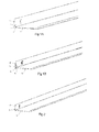
- FIG. 1a depicts a shelf (1) according to the invention.
- Shelf (1) comprises a rear face (2) provided with an opening (3) and a deformable region (4) at least in rear face (2) and potentially also extending into a support surface (5) portion of shelf (1).
- support surface (5) is configured as desired based on the demands of the objects to be held on shelf (1), and can compose an optional support surface opening (6).
- rear face opening (3) and support surface opening (6) are shown as slit-like openings. Any suitable shape for an opening is applicable to this invention, and further configurations will be described in detail below. Furthermore, some embodiments of the invention have no opening, as will also be detailed below, in particular with regard to Figure 2 .
- Figure 2 shows an alternate embodiment of a shelf (1) having a rear face (2) with a deformable region (4) in the form of a tab or extension protruding therefrom. Neither rear face (2) nor support surface (5) have been provided with openings in this embodiment.
- shelves are possible. For example, in some cases it may be desirable to provide a lip or upwardly-extending portion along the support surface to prevent items on the shelf from failing off. Materials used for the shelf will also be dictated on usage requirements. For example, where shelves are visible during use the outward appearance of the chosen material may be a factor to consider. Generally, ease of manufacture and use and strength, particularly as a factor of weight and cost, are aspects taken into account by the skilled person. Some examples of materials useful with the invention include zinc coated steel and extruded aluminium.
- FIG. 3 depicts a base unit (7).
- Base unit (7) comprises a first profile (8) and a second profile (9).
- First and second profiles (8,9) are connected to a base unit rear face (10). While a particular configuration for base unit (7) and first and second profiles (8,9) is shown, it will be apparent to a skilled worker that innumerable configurations will be possible of different base units and profiles, all of which can be suitably adapted to cooperate with a shelf of the invention.
- FIGs 4a and 4b show a sequence by which a user can place a shelf in a base unit.
- rear face (2) of shelf (1) is inserted between first and second profiles (8,9) of base unit (7).
- Shelf rear face (2) is dimensioned to allow movement through the opening created between first and second profiles (8,9).
- a user has pressed shelf (1) downward and rearward such that rear face (2) of shelf (1) is parallel and adjacent to rear face (10) of base unit (7).
- the dimensions of shelf rear face (2) ensure that shelf (1) is able to rest on second profile (9) while being retained and resisting movement away from base unit rear face (10) by first profile (8).
- shelf (1) is limited in both upward and outward movement by first profile (8). Shelf (1) is also limited in downward movement by second profile (9). However, shelf can slide laterally along second profile (9) and, by lifting shelf (1) slightly, it can be removed in a reverse fashion as compared to the placement. In some situations, this ability to remove shelf (1) and/or position shelf (1) vertically along base unit (7) at this stage of assembly is highly desirable. Once shelf (1) is in the desired position, it can be locked into place to prevent undesired removal of shelf (1) from base unit (7), which locking may also serve to prevent or slow sliding of shelf (1) along the length of base unit (7).
- Figures 5a-e depict a simulated sequence whereby a cable shelf employing the inventive features is inserted and locked in a trunking base.
- shelf (1) is provided with rear face openings (3) at each terminal end.
- Fig 5c shows the locking procedure with respect to a first end
- Figure 5e shows the locking procedure with respect to the second end.
- a shelf having at least one deformable portion either at an end or located along the length of the shelf will fulfil the criteria of the present invention.
- shelf (1) is located in the desired position along base unit (7).
- a first profile is not shown.
- Support surface (5) of shelf (1) rests on second profile (9).
- Figure 6a to 6b one sees how a user has manipulated opening (3) to force deformable region (4) into a gap between second profile (9) and rear face (10) of base unit (7).
- opening (3) can preferably be manipulated using a standard flat-head screwdriver. This is a common tool available in a wide range of sizes, which could therefore be used with a wide range of shelf and opening sizes.
- the opening shown in this embodiment also has the distinct advantage of being very easily manipulated. Assuming materials with a suitable deformability are chosen a user can simply insert a screwdriver in the opening and perform a slight rotational movement to cause the deformation shown in Figure 6b . This may be particularly advantageous in situations where a single user is performing the steps shown in the figures. They can use one hand to hold the shelf in place while using the other hand to effect the manipulation. At the stage shown in Figure 6b , the shelf is locked in place and items such as cables can be placed upon the shelf without worry that the shelf will move unexpectedly.
- an opening is provided in the rear face of the shelf, any configuration can be used. If it is desirable to limit the locking procedure an opening which can only be manipulated by a specially-designed tool could be used. Not only the shape but also the size of the opening in the rear face of the shelf can be variable. This helps to accommodate various materials, the relative physical proposes of which may call for more or less manipulation or torque to cause the deformation.
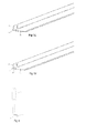
- Figures 7a-f depict a few possible configurations. Note in Figure 7a there is a triangular opening (3) in rear face (2) of shelf (1) but no opening in support surface (5) of shelf (1). This may result in a lesser degree of deformation and thus a lesser degree of locking.
- Figure 7b shows curved openings (3, 6) which may offer ease of manufacture where pre-drilling of other circular or semi-circular shapes is being made.
- Figure 7c again shows slot-shaped openings (3, 6) however these are at an angle relative to an edge of shelf (1).
- Such a configuration may be desirable where shelf (1) is eventually to be removed, the deformable portion (4) being more easily torn away from shelf and retained by the base unit (not shown) in such an application.
- Figure 7d shows a plurality of openings (3) in rear face (2) of shelf (1). It also depicts how openings (3) need not necessarily be provided flush with an edge of shelf (1).
- oversized shelving components are provided or purchased in bulk and cut to size during installation. By pre-forming a plurality of openings in such a shelf component, users may be more likely to have at least one opening in a shelf which can facilitate deformation of a deformable part and thus locking of the shelf in position.
- Figures 7e and 7f show an embodiment where a deformable portion extends from shelf (1) as opposed to being an inherent part of shelf (1).
- the Figure 7e embodiment can be located as desired, then using a tool such as a screwdriver or pliers the deformable region (4), in this embodiment a tab, can be bent or pushed into position such that the shelf is locked in place.
- the Figure 7f embodiment has a laterally-extending deformable region (4) similar to Figure 7e and also depicts an opening (3) in the form of a hole.
- a tool having a first portion designed to engage opening (3) hole could be inserted into opening (3) and rotated such that a second portion of such a tool could deform the deformable portion (4).
- a schematic cross-sectional view of such a tool (11) is shown in Figure 8 , where a first, opening-engaging portion (12) and a second, deforming portion (13) are depicted.
- the present figures also depict the base unit as having two T-shaped profiles. Any number and configuration of profiles could of course be used. When choosing an alternate profile a skilled person would reflect on such things as shape of the profile and deformability of the shelf when optimising the shape, size, and placement of profiles and deformable regions.
- FIG. 1 While the figures generally show a base unit and shelf which find use in cable bundling applications, skilled persons will recognize the wide applicability of the present invention. Furthermore, the embodiments shown and described relate to shelves which are to be placed in a horizontal orientation. The invention nonetheless could be used in applications where the shelf is not in a horizontal position, and thus serves more as a divider than a supporting member.
Landscapes
- Assembled Shelves (AREA)
Abstract
Description
- The invention relates to shelving systems. More particularly, the invention relates to a shelf comprising a deformable portion adapted to lock the position of the shelf relative to a profile member.
- Shelving systems are as plentiful and diverse as the objects to be placed upon them. Some basic characteristics shared by many are a base unit secured to and generally parallel with a wall, and a plurality of horizontal shelves provided on or in the base unit.
- In certain applications, it can be desirable to provide shelves which can be inserted at a desired location then later moved to a new location. For example,
WO 94/02050 - Another shelving application is the organisation and storage of routed cables. Advanced systems for power, data, or telephony transmittal can depend upon extensive cable systems. For this purpose, the various cables can be supported and separated on a plurality of cable shelves provided inside a base unit, also called a trunking base.
- However, when shelves are loosely seated relative to the base unit, undesired dislodgement or movement of the shelf can result.
-
US 4,765,575 describes a shelf and support combination. The support has profiles which engage the shelf. When the user forces or presses the shelf into place in relation to the profiles, a deformable region of a profile lockingly engages the shelf in a stationary position. Accordingly, the user must ensure the shelf is in the desired final position relative to the support before pushing the shelf into place. - Thus, while there are available shelving systems and known means to lock a shelf into place relative to a support, there nonetheless remains a need in the art for improved shelves and shelving systems.
- Therefore, a goal of the present invention is to provide an improved shelf for use with a base unit, which shelf can engage a base unit and be moved about into a desired position. At this time, the shelf may be easily lockingly engaged with the base unit thus solving the problems inherent in the prior art.
- These and other goals are achieved by a shelf of the invention which comprises a support surface extending from a rear face, the rear face being locatable between a first profile and a second profile, wherein the first profile fixes the rear face in two directions at right angles to one another and the second profile fixes the rear face in a first of the two directions, the shelf comprising a deformable region, deformation of which locks the rear face and thus the shelf relative to the second profile in the second of said two directions.
- A shelf according to the invention may further comprise a rear face opening which is engageable with a tool and having a deformable region proximate to the rear face opening, wherein manipulation of a tool engaged in the rear face opening deforms the deformable region locking the rear face and thus the shelf relative to the second profile in the second of said two directions.
- In a shelf according to the invention the support surface may comprise a support surface opening. The rear face opening and support surface opening may comprise a gap or a slit. Manipulation could comprise rotation.
- According to another embodiment of the invention there is provided a shelf system which comprises a base unit having a first profile and a second profile and a shelf having a rear face, the rear face of the shelf being arranged between the first profile and the second profile and being fixed in two directions at right angles to one another by the first profile, and fixed in a first of the two directions by second profile, where the shelf comprises a deformable region capable of being deformed such that the shelf is fixed by the second profile in the second of the two directions.
- Such a shelf system could comprise a base unit which is mounted on a wall.
- As used herein, the terms "lock," "locking," and "lockingly" as well as "fix" and "fixedly" refer to a relative state of immobilisation. It will be evident to a skilled person that a shelf described as being in one of these states could nonetheless be moved and/or removed provided a sufficient amount of force is employed. Thus, these terms relate to a state in which ordinary forces experienced by the shelf are generally insufficient to move the shelf.
- In order that the present invention may be clearly understood and readily carried into effect, reference will now be made, by way of example only, to the accompanying drawings in which:
-
Figure 1a shows a diagrammatic perspective view of a shelf in a non-deformed state; -
Figure 1b shows a diagrammatic perspective view of a shelf in a deformed state; -
Figure 2 shows a diagrammatic perspective view of a shelf in a non-deformed state; -
Figure 3 shows a diagrammatic end elevation of a base unit; -
Figure 4a shows a diagrammatic end elevation of a base unit with a shelf partially in position in the base unit; -
Figure 4b shows a diagrammatic end elevation of a base unit with a shelf completely in position in the base unit; -
Figures 5a-e schematically show a sequence of steps in which a shelf is locked in a base unit; -
Figure 6a shows a diagrammatic perspective view of a base unit with a non-deformed shelf in the base unit; -
Figure 6b shows a diagrammatic perspective view of a base unit with a deformed shelf in the base unit; -
Figures 7a through 7f show diagrammatic perspective views of a portion of further embodiments of a shelf, all in a non-deformed state; and -
Figure 8 shows a cross section of a tool which could be of use with an embodiment according tofigure 7f . - Features in common to more than one figure will be denoted by the same reference numeral.
-
Figure 1a depicts a shelf (1) according to the invention. Shelf (1) comprises a rear face (2) provided with an opening (3) and a deformable region (4) at least in rear face (2) and potentially also extending into a support surface (5) portion of shelf (1). Just as rear face (2) is proportioned based on usage demands, support surface (5) is configured as desired based on the demands of the objects to be held on shelf (1), and can compose an optional support surface opening (6). - In this embodiment rear face opening (3) and support surface opening (6) are shown as slit-like openings. Any suitable shape for an opening is applicable to this invention, and further configurations will be described in detail below. Furthermore, some embodiments of the invention have no opening, as will also be detailed below, in particular with regard to
Figure 2 . - In
Figure 1b the shelf (1) ofFigure 1 a has been manipulated such that deformable region (4) is deformed. The shape of rear face opening (3) and support surface opening (6) have changed as a result of the movement of deformable region (4). -
Figure 2 shows an alternate embodiment of a shelf (1) having a rear face (2) with a deformable region (4) in the form of a tab or extension protruding therefrom. Neither rear face (2) nor support surface (5) have been provided with openings in this embodiment. - A skilled person will appreciate that various sizes and shapes of shelves are possible. For example, in some cases it may be desirable to provide a lip or upwardly-extending portion along the support surface to prevent items on the shelf from failing off. Materials used for the shelf will also be dictated on usage requirements. For example, where shelves are visible during use the outward appearance of the chosen material may be a factor to consider. Generally, ease of manufacture and use and strength, particularly as a factor of weight and cost, are aspects taken into account by the skilled person. Some examples of materials useful with the invention include zinc coated steel and extruded aluminium.
- Further materials could also be employed such as PVC and other plastics. However, in cases where the desired material for the shelf is not deformable or not suitably deformable, a deformable region must be added or otherwise provided with or in a shelf.
-
Figure 3 depicts a base unit (7). Base unit (7) comprises a first profile (8) and a second profile (9). First and second profiles (8,9) are connected to a base unit rear face (10). While a particular configuration for base unit (7) and first and second profiles (8,9) is shown, it will be apparent to a skilled worker that innumerable configurations will be possible of different base units and profiles, all of which can be suitably adapted to cooperate with a shelf of the invention. - In many applications it is desired to affix a base unit to an object such as a panel or a wall either by direct mounting or using brackets. Any conventional fasteners could be used for this purpose, depending on factors such as the overall weight and stresses of the objects concerned, as well as the environment to which they are exposed. For ease of illustration such fasteners are not depicted.
-
Figures 4a and 4b show a sequence by which a user can place a shelf in a base unit. InFigure 4a , rear face (2) of shelf (1) is inserted between first and second profiles (8,9) of base unit (7). Shelf rear face (2) is dimensioned to allow movement through the opening created between first and second profiles (8,9). Referring now toFigure 4B , a user has pressed shelf (1) downward and rearward such that rear face (2) of shelf (1) is parallel and adjacent to rear face (10) of base unit (7). The dimensions of shelf rear face (2) ensure that shelf (1) is able to rest on second profile (9) while being retained and resisting movement away from base unit rear face (10) by first profile (8). - At this stage, a user has successfully placed shelf (1) in base unit (7) and shelf is limited in both upward and outward movement by first profile (8). Shelf (1) is also limited in downward movement by second profile (9). However, shelf can slide laterally along second profile (9) and, by lifting shelf (1) slightly, it can be removed in a reverse fashion as compared to the placement. In some situations, this ability to remove shelf (1) and/or position shelf (1) vertically along base unit (7) at this stage of assembly is highly desirable. Once shelf (1) is in the desired position, it can be locked into place to prevent undesired removal of shelf (1) from base unit (7), which locking may also serve to prevent or slow sliding of shelf (1) along the length of base unit (7).
-
Figures 5a-e depict a simulated sequence whereby a cable shelf employing the inventive features is inserted and locked in a trunking base. In this particular configuration, shelf (1) is provided with rear face openings (3) at each terminal end.Fig 5c shows the locking procedure with respect to a first end, andFigure 5e shows the locking procedure with respect to the second end. As will be apparent to a skilled worker, a shelf having at least one deformable portion either at an end or located along the length of the shelf will fulfil the criteria of the present invention. - As shown in
Figures 6a and 6b , shelf (1) is located in the desired position along base unit (7). For ease of illustration a first profile is not shown. Support surface (5) of shelf (1) rests on second profile (9). Moving fromFigure 6a to 6b one sees how a user has manipulated opening (3) to force deformable region (4) into a gap between second profile (9) and rear face (10) of base unit (7). - When configured as a slot, as shown in the
Figure 6a and 6b embodiment, opening (3) can preferably be manipulated using a standard flat-head screwdriver. This is a common tool available in a wide range of sizes, which could therefore be used with a wide range of shelf and opening sizes. The opening shown in this embodiment also has the distinct advantage of being very easily manipulated. Assuming materials with a suitable deformability are chosen a user can simply insert a screwdriver in the opening and perform a slight rotational movement to cause the deformation shown inFigure 6b . This may be particularly advantageous in situations where a single user is performing the steps shown in the figures. They can use one hand to hold the shelf in place while using the other hand to effect the manipulation. At the stage shown inFigure 6b , the shelf is locked in place and items such as cables can be placed upon the shelf without worry that the shelf will move unexpectedly. - As previously noted, if an opening is provided in the rear face of the shelf, any configuration can be used. If it is desirable to limit the locking procedure an opening which can only be manipulated by a specially-designed tool could be used. Not only the shape but also the size of the opening in the rear face of the shelf can be variable. This helps to accommodate various materials, the relative physical proposes of which may call for more or less manipulation or torque to cause the deformation.
-
Figures 7a-f depict a few possible configurations. Note inFigure 7a there is a triangular opening (3) in rear face (2) of shelf (1) but no opening in support surface (5) of shelf (1). This may result in a lesser degree of deformation and thus a lesser degree of locking.Figure 7b shows curved openings (3, 6) which may offer ease of manufacture where pre-drilling of other circular or semi-circular shapes is being made.Figure 7c again shows slot-shaped openings (3, 6) however these are at an angle relative to an edge of shelf (1). Such a configuration may be desirable where shelf (1) is eventually to be removed, the deformable portion (4) being more easily torn away from shelf and retained by the base unit (not shown) in such an application. - The embodiment of
Figure 7d shows a plurality of openings (3) in rear face (2) of shelf (1). It also depicts how openings (3) need not necessarily be provided flush with an edge of shelf (1). In many applications oversized shelving components are provided or purchased in bulk and cut to size during installation. By pre-forming a plurality of openings in such a shelf component, users may be more likely to have at least one opening in a shelf which can facilitate deformation of a deformable part and thus locking of the shelf in position. -
Figures 7e and 7f show an embodiment where a deformable portion extends from shelf (1) as opposed to being an inherent part of shelf (1). TheFigure 7e embodiment can be located as desired, then using a tool such as a screwdriver or pliers the deformable region (4), in this embodiment a tab, can be bent or pushed into position such that the shelf is locked in place. - The
Figure 7f embodiment has a laterally-extending deformable region (4) similar toFigure 7e and also depicts an opening (3) in the form of a hole. In such an embodiment, a tool having a first portion designed to engage opening (3) hole could be inserted into opening (3) and rotated such that a second portion of such a tool could deform the deformable portion (4). A schematic cross-sectional view of such a tool (11) is shown inFigure 8 , where a first, opening-engaging portion (12) and a second, deforming portion (13) are depicted. - In addition to the generalisations used for representing shelves according to the invention, the present figures also depict the base unit as having two T-shaped profiles. Any number and configuration of profiles could of course be used. When choosing an alternate profile a skilled person would reflect on such things as shape of the profile and deformability of the shelf when optimising the shape, size, and placement of profiles and deformable regions.
- While the figures generally show a base unit and shelf which find use in cable bundling applications, skilled persons will recognize the wide applicability of the present invention. Furthermore, the embodiments shown and described relate to shelves which are to be placed in a horizontal orientation. The invention nonetheless could be used in applications where the shelf is not in a horizontal position, and thus serves more as a divider than a supporting member.
- The description, examples, and figures have been set forth merely to illustrate the invention and are not intended to be limiting. Since modifications of the described embodiments incorporating the spirit and substance of the invention may occur to persons skilled in the art, the invention should be construed broadly to include all variations within the scope of the appended claims and equivalents thereof.
Claims (7)
- A shelf (1) comprising a rear face (2) locatable between a first profile (8) and a second profile (9) and a support surface (5) extending from the rear face (2), wherein the first profile (8) fixes the rear face (2) in two directions at right angles to one another and the second profile (9) fixes the rear face (2) in a first of the two directions characterised in that the shelf (1) comprises at least one rear face deformable region (4) wherein deformation of the rear face deformable region (4) locks the rear face (2) and thus the shelf (1) relative to the second profile (9) in the second of said two directions.
- A shelf (1) according to claim 1, wherein the shelf (1) comprises a rear face opening (3) engageable with a tool and a rear face deformable region (4) located proximate to the rear face opening (3) wherein manipulation of a tool engaged in the rear face opening (3) deforms the rear face deformable region (4) locking the rear face (2) and thus the shelf (1) relative to the second profile (9) in the second of said two directions.
- A shelf (1) according to either claim 1 or claim 2, wherein the support surface (5) comprises a support surface opening (6).
- A shelf (1) according to claim 3, wherein rear face opening (3) and support surface opening (6) comprise a gap or a slit.
- A shelf according to any of claims 2 through 4, wherein manipulation comprises rotation.
- A shelf system comprising a base unit (7) having a first profile (8) and a second profile (9) and a shelf (1) having a rear face (2) and a support surface (5) extending from the rear face (2), the rear face (2) of the shelf (1) being arranged between the first profile (8) and the second profile (9) and being fixed in two directions at right angles to one another by the first profile (8), and fixed in a first of the two directions by second profile (9) characterised in that the rear face (2) of the shelf (1) comprises at least one deformable region (4) capable of being deformed such that the rear face (2) of the shelf (1) is fixed by the second profile (9) in the second of said two directions.
- A shelf system according to claim 6, wherein the base unit (7) is mounted on a wall.
Applications Claiming Priority (1)
| Application Number | Priority Date | Filing Date | Title |
|---|---|---|---|
| SE0950237A SE534098C2 (en) | 2009-04-09 | 2009-04-09 | Lockable shelf and shelf system |
Publications (3)
| Publication Number | Publication Date |
|---|---|
| EP2238867A2 true EP2238867A2 (en) | 2010-10-13 |
| EP2238867A3 EP2238867A3 (en) | 2014-05-21 |
| EP2238867B1 EP2238867B1 (en) | 2017-08-23 |
Family
ID=42371534
Family Applications (1)
| Application Number | Title | Priority Date | Filing Date |
|---|---|---|---|
| EP10159172.5A Not-in-force EP2238867B1 (en) | 2009-04-09 | 2010-04-06 | Shelf system |
Country Status (2)
| Country | Link |
|---|---|
| EP (1) | EP2238867B1 (en) |
| SE (1) | SE534098C2 (en) |
Cited By (1)
| Publication number | Priority date | Publication date | Assignee | Title |
|---|---|---|---|---|
| US20210131117A1 (en) * | 2019-08-30 | 2021-05-06 | Nine O, Llc | Wall system with fulcrum release and replaceable units |
Citations (2)
| Publication number | Priority date | Publication date | Assignee | Title |
|---|---|---|---|---|
| US4765575A (en) | 1987-03-18 | 1988-08-23 | Modulus, Inc. | Cantilever shelf support |
| WO1994002050A1 (en) | 1992-07-22 | 1994-02-03 | Crooymans Rene Wilhelm | Shelving support system |
Family Cites Families (3)
| Publication number | Priority date | Publication date | Assignee | Title |
|---|---|---|---|---|
| SE500193C2 (en) * | 1991-12-04 | 1994-05-02 | Erik Jelbring | Cable Channel |
| DE4327203C2 (en) * | 1993-08-13 | 1995-06-14 | Wittner Gmbh & Co Rudolf | Device for archiving cartridges |
| FR2904459B1 (en) * | 2006-07-27 | 2008-10-24 | Joalpe Ind De Expositores Sa | PROFILE LABEL HOLDER OR PROFILE HOLDER FOR FASTENING REMOVABLE LABEL HOLDER. |
-
2009
- 2009-04-09 SE SE0950237A patent/SE534098C2/en unknown
-
2010
- 2010-04-06 EP EP10159172.5A patent/EP2238867B1/en not_active Not-in-force
Patent Citations (2)
| Publication number | Priority date | Publication date | Assignee | Title |
|---|---|---|---|---|
| US4765575A (en) | 1987-03-18 | 1988-08-23 | Modulus, Inc. | Cantilever shelf support |
| WO1994002050A1 (en) | 1992-07-22 | 1994-02-03 | Crooymans Rene Wilhelm | Shelving support system |
Cited By (2)
| Publication number | Priority date | Publication date | Assignee | Title |
|---|---|---|---|---|
| US20210131117A1 (en) * | 2019-08-30 | 2021-05-06 | Nine O, Llc | Wall system with fulcrum release and replaceable units |
| US11891811B2 (en) * | 2019-08-30 | 2024-02-06 | Nine O, Llc | Wall system with fulcrum release and replaceable units |
Also Published As
| Publication number | Publication date |
|---|---|
| SE0950237A1 (en) | 2010-10-10 |
| EP2238867A3 (en) | 2014-05-21 |
| EP2238867B1 (en) | 2017-08-23 |
| SE534098C2 (en) | 2011-04-26 |
Similar Documents
| Publication | Publication Date | Title |
|---|---|---|
| EP1752072B1 (en) | Display mounting system | |
| CA2672127C (en) | Storage systems and methods of use of the same | |
| EP2416679B1 (en) | An assembly system for connecting furniture elements | |
| US6220461B1 (en) | Slant shelf system | |
| US6036149A (en) | Hanger for gypsum board by compression | |
| CA1051830A (en) | Device for lockably securing appurtenances to a decorative wall | |
| US20120298819A1 (en) | Wall storage mounting arrangements | |
| US20100327134A1 (en) | Mount with separate device interface | |
| EP3267848B1 (en) | Support means | |
| US6749161B1 (en) | Slatwall mounting bracket | |
| US9591932B2 (en) | Bracket and wall standard assembly | |
| US20110303798A1 (en) | Wall storage mounting system | |
| CN108348077A (en) | Buckle cross bar | |
| US7261213B2 (en) | Closet partition system | |
| AU2020338407B2 (en) | Wall anchors and assemblies for heavyweight objects | |
| US12049758B1 (en) | Apparatus and method for hanging architectural panels with concealed attachment points | |
| US11589688B2 (en) | System to support cantilevered members from a vertical panel | |
| US4821892A (en) | Shelving system | |
| EP2238867B1 (en) | Shelf system | |
| AU2010306403A1 (en) | Wall mountable storage | |
| US20060266901A1 (en) | Slotwall mounting bracket | |
| CN115120075A (en) | Flexible shelving unit | |
| US20070199222A1 (en) | Display support device | |
| US20070181759A1 (en) | Shelving system | |
| AU2024259842A1 (en) | Expandable blanking panel assembly for aisles in data centers and similar facilities |
Legal Events
| Date | Code | Title | Description |
|---|---|---|---|
| PUAI | Public reference made under article 153(3) epc to a published international application that has entered the european phase |
Free format text: ORIGINAL CODE: 0009012 |
|
| AK | Designated contracting states |
Kind code of ref document: A2 Designated state(s): AT BE BG CH CY CZ DE DK EE ES FI FR GB GR HR HU IE IS IT LI LT LU LV MC MK MT NL NO PL PT RO SE SI SK SM TR |
|
| AX | Request for extension of the european patent |
Extension state: AL BA ME RS |
|
| PUAL | Search report despatched |
Free format text: ORIGINAL CODE: 0009013 |
|
| AK | Designated contracting states |
Kind code of ref document: A3 Designated state(s): AT BE BG CH CY CZ DE DK EE ES FI FR GB GR HR HU IE IS IT LI LT LU LV MC MK MT NL NO PL PT RO SE SI SK SM TR |
|
| AX | Request for extension of the european patent |
Extension state: AL BA ME RS |
|
| RIC1 | Information provided on ipc code assigned before grant |
Ipc: A47B 96/02 20060101AFI20140414BHEP |
|
| 17P | Request for examination filed |
Effective date: 20141121 |
|
| RBV | Designated contracting states (corrected) |
Designated state(s): AT BE BG CH CY CZ DE DK EE ES FI FR GB GR HR HU IE IS IT LI LT LU LV MC MK MT NL NO PL PT RO SE SI SK SM TR |
|
| 17Q | First examination report despatched |
Effective date: 20170217 |
|
| GRAP | Despatch of communication of intention to grant a patent |
Free format text: ORIGINAL CODE: EPIDOSNIGR1 |
|
| INTG | Intention to grant announced |
Effective date: 20170509 |
|
| GRAS | Grant fee paid |
Free format text: ORIGINAL CODE: EPIDOSNIGR3 |
|
| GRAA | (expected) grant |
Free format text: ORIGINAL CODE: 0009210 |
|
| RIN1 | Information on inventor provided before grant (corrected) |
Inventor name: WESTLIN, STEFAN |
|
| AK | Designated contracting states |
Kind code of ref document: B1 Designated state(s): AT BE BG CH CY CZ DE DK EE ES FI FR GB GR HR HU IE IS IT LI LT LU LV MC MK MT NL NO PL PT RO SE SI SK SM TR |
|
| REG | Reference to a national code |
Ref country code: GB Ref legal event code: FG4D |
|
| REG | Reference to a national code |
Ref country code: CH Ref legal event code: EP |
|
| REG | Reference to a national code |
Ref country code: AT Ref legal event code: REF Ref document number: 920357 Country of ref document: AT Kind code of ref document: T Effective date: 20170915 |
|
| REG | Reference to a national code |
Ref country code: IE Ref legal event code: FG4D |
|
| REG | Reference to a national code |
Ref country code: DE Ref legal event code: R096 Ref document number: 602010044555 Country of ref document: DE |
|
| REG | Reference to a national code |
Ref country code: NL Ref legal event code: MP Effective date: 20170823 |
|
| REG | Reference to a national code |
Ref country code: LT Ref legal event code: MG4D |
|
| REG | Reference to a national code |
Ref country code: AT Ref legal event code: MK05 Ref document number: 920357 Country of ref document: AT Kind code of ref document: T Effective date: 20170823 |
|
| PG25 | Lapsed in a contracting state [announced via postgrant information from national office to epo] |
Ref country code: SE Free format text: LAPSE BECAUSE OF FAILURE TO SUBMIT A TRANSLATION OF THE DESCRIPTION OR TO PAY THE FEE WITHIN THE PRESCRIBED TIME-LIMIT Effective date: 20170823 Ref country code: AT Free format text: LAPSE BECAUSE OF FAILURE TO SUBMIT A TRANSLATION OF THE DESCRIPTION OR TO PAY THE FEE WITHIN THE PRESCRIBED TIME-LIMIT Effective date: 20170823 Ref country code: LT Free format text: LAPSE BECAUSE OF FAILURE TO SUBMIT A TRANSLATION OF THE DESCRIPTION OR TO PAY THE FEE WITHIN THE PRESCRIBED TIME-LIMIT Effective date: 20170823 Ref country code: NO Free format text: LAPSE BECAUSE OF FAILURE TO SUBMIT A TRANSLATION OF THE DESCRIPTION OR TO PAY THE FEE WITHIN THE PRESCRIBED TIME-LIMIT Effective date: 20171123 Ref country code: HR Free format text: LAPSE BECAUSE OF FAILURE TO SUBMIT A TRANSLATION OF THE DESCRIPTION OR TO PAY THE FEE WITHIN THE PRESCRIBED TIME-LIMIT Effective date: 20170823 Ref country code: FI Free format text: LAPSE BECAUSE OF FAILURE TO SUBMIT A TRANSLATION OF THE DESCRIPTION OR TO PAY THE FEE WITHIN THE PRESCRIBED TIME-LIMIT Effective date: 20170823 Ref country code: NL Free format text: LAPSE BECAUSE OF FAILURE TO SUBMIT A TRANSLATION OF THE DESCRIPTION OR TO PAY THE FEE WITHIN THE PRESCRIBED TIME-LIMIT Effective date: 20170823 |
|
| PG25 | Lapsed in a contracting state [announced via postgrant information from national office to epo] |
Ref country code: ES Free format text: LAPSE BECAUSE OF FAILURE TO SUBMIT A TRANSLATION OF THE DESCRIPTION OR TO PAY THE FEE WITHIN THE PRESCRIBED TIME-LIMIT Effective date: 20170823 Ref country code: PL Free format text: LAPSE BECAUSE OF FAILURE TO SUBMIT A TRANSLATION OF THE DESCRIPTION OR TO PAY THE FEE WITHIN THE PRESCRIBED TIME-LIMIT Effective date: 20170823 Ref country code: LV Free format text: LAPSE BECAUSE OF FAILURE TO SUBMIT A TRANSLATION OF THE DESCRIPTION OR TO PAY THE FEE WITHIN THE PRESCRIBED TIME-LIMIT Effective date: 20170823 Ref country code: GR Free format text: LAPSE BECAUSE OF FAILURE TO SUBMIT A TRANSLATION OF THE DESCRIPTION OR TO PAY THE FEE WITHIN THE PRESCRIBED TIME-LIMIT Effective date: 20171124 Ref country code: BG Free format text: LAPSE BECAUSE OF FAILURE TO SUBMIT A TRANSLATION OF THE DESCRIPTION OR TO PAY THE FEE WITHIN THE PRESCRIBED TIME-LIMIT Effective date: 20171123 Ref country code: IS Free format text: LAPSE BECAUSE OF FAILURE TO SUBMIT A TRANSLATION OF THE DESCRIPTION OR TO PAY THE FEE WITHIN THE PRESCRIBED TIME-LIMIT Effective date: 20171223 |
|
| PG25 | Lapsed in a contracting state [announced via postgrant information from national office to epo] |
Ref country code: DK Free format text: LAPSE BECAUSE OF FAILURE TO SUBMIT A TRANSLATION OF THE DESCRIPTION OR TO PAY THE FEE WITHIN THE PRESCRIBED TIME-LIMIT Effective date: 20170823 Ref country code: CZ Free format text: LAPSE BECAUSE OF FAILURE TO SUBMIT A TRANSLATION OF THE DESCRIPTION OR TO PAY THE FEE WITHIN THE PRESCRIBED TIME-LIMIT Effective date: 20170823 Ref country code: RO Free format text: LAPSE BECAUSE OF FAILURE TO SUBMIT A TRANSLATION OF THE DESCRIPTION OR TO PAY THE FEE WITHIN THE PRESCRIBED TIME-LIMIT Effective date: 20170823 |
|
| REG | Reference to a national code |
Ref country code: DE Ref legal event code: R097 Ref document number: 602010044555 Country of ref document: DE |
|
| PG25 | Lapsed in a contracting state [announced via postgrant information from national office to epo] |
Ref country code: IT Free format text: LAPSE BECAUSE OF FAILURE TO SUBMIT A TRANSLATION OF THE DESCRIPTION OR TO PAY THE FEE WITHIN THE PRESCRIBED TIME-LIMIT Effective date: 20170823 Ref country code: SK Free format text: LAPSE BECAUSE OF FAILURE TO SUBMIT A TRANSLATION OF THE DESCRIPTION OR TO PAY THE FEE WITHIN THE PRESCRIBED TIME-LIMIT Effective date: 20170823 Ref country code: EE Free format text: LAPSE BECAUSE OF FAILURE TO SUBMIT A TRANSLATION OF THE DESCRIPTION OR TO PAY THE FEE WITHIN THE PRESCRIBED TIME-LIMIT Effective date: 20170823 Ref country code: SM Free format text: LAPSE BECAUSE OF FAILURE TO SUBMIT A TRANSLATION OF THE DESCRIPTION OR TO PAY THE FEE WITHIN THE PRESCRIBED TIME-LIMIT Effective date: 20170823 |
|
| PLBE | No opposition filed within time limit |
Free format text: ORIGINAL CODE: 0009261 |
|
| STAA | Information on the status of an ep patent application or granted ep patent |
Free format text: STATUS: NO OPPOSITION FILED WITHIN TIME LIMIT |
|
| 26N | No opposition filed |
Effective date: 20180524 |
|
| PG25 | Lapsed in a contracting state [announced via postgrant information from national office to epo] |
Ref country code: SI Free format text: LAPSE BECAUSE OF FAILURE TO SUBMIT A TRANSLATION OF THE DESCRIPTION OR TO PAY THE FEE WITHIN THE PRESCRIBED TIME-LIMIT Effective date: 20170823 |
|
| REG | Reference to a national code |
Ref country code: DE Ref legal event code: R119 Ref document number: 602010044555 Country of ref document: DE |
|
| PG25 | Lapsed in a contracting state [announced via postgrant information from national office to epo] |
Ref country code: MC Free format text: LAPSE BECAUSE OF FAILURE TO SUBMIT A TRANSLATION OF THE DESCRIPTION OR TO PAY THE FEE WITHIN THE PRESCRIBED TIME-LIMIT Effective date: 20170823 |
|
| REG | Reference to a national code |
Ref country code: CH Ref legal event code: PL |
|
| REG | Reference to a national code |
Ref country code: BE Ref legal event code: MM Effective date: 20180430 |
|
| GBPC | Gb: european patent ceased through non-payment of renewal fee |
Effective date: 20180406 |
|
| REG | Reference to a national code |
Ref country code: IE Ref legal event code: MM4A |
|
| PG25 | Lapsed in a contracting state [announced via postgrant information from national office to epo] |
Ref country code: LU Free format text: LAPSE BECAUSE OF NON-PAYMENT OF DUE FEES Effective date: 20180406 Ref country code: DE Free format text: LAPSE BECAUSE OF NON-PAYMENT OF DUE FEES Effective date: 20181101 |
|
| PG25 | Lapsed in a contracting state [announced via postgrant information from national office to epo] |
Ref country code: BE Free format text: LAPSE BECAUSE OF NON-PAYMENT OF DUE FEES Effective date: 20180430 Ref country code: LI Free format text: LAPSE BECAUSE OF NON-PAYMENT OF DUE FEES Effective date: 20180430 Ref country code: GB Free format text: LAPSE BECAUSE OF NON-PAYMENT OF DUE FEES Effective date: 20180406 Ref country code: CH Free format text: LAPSE BECAUSE OF NON-PAYMENT OF DUE FEES Effective date: 20180430 |
|
| PG25 | Lapsed in a contracting state [announced via postgrant information from national office to epo] |
Ref country code: FR Free format text: LAPSE BECAUSE OF NON-PAYMENT OF DUE FEES Effective date: 20180430 Ref country code: IE Free format text: LAPSE BECAUSE OF NON-PAYMENT OF DUE FEES Effective date: 20180406 |
|
| PG25 | Lapsed in a contracting state [announced via postgrant information from national office to epo] |
Ref country code: MT Free format text: LAPSE BECAUSE OF NON-PAYMENT OF DUE FEES Effective date: 20180406 |
|
| PG25 | Lapsed in a contracting state [announced via postgrant information from national office to epo] |
Ref country code: TR Free format text: LAPSE BECAUSE OF FAILURE TO SUBMIT A TRANSLATION OF THE DESCRIPTION OR TO PAY THE FEE WITHIN THE PRESCRIBED TIME-LIMIT Effective date: 20170823 |
|
| PG25 | Lapsed in a contracting state [announced via postgrant information from national office to epo] |
Ref country code: HU Free format text: LAPSE BECAUSE OF FAILURE TO SUBMIT A TRANSLATION OF THE DESCRIPTION OR TO PAY THE FEE WITHIN THE PRESCRIBED TIME-LIMIT; INVALID AB INITIO Effective date: 20100406 Ref country code: PT Free format text: LAPSE BECAUSE OF FAILURE TO SUBMIT A TRANSLATION OF THE DESCRIPTION OR TO PAY THE FEE WITHIN THE PRESCRIBED TIME-LIMIT Effective date: 20170823 |
|
| PG25 | Lapsed in a contracting state [announced via postgrant information from national office to epo] |
Ref country code: MK Free format text: LAPSE BECAUSE OF NON-PAYMENT OF DUE FEES Effective date: 20170823 Ref country code: CY Free format text: LAPSE BECAUSE OF FAILURE TO SUBMIT A TRANSLATION OF THE DESCRIPTION OR TO PAY THE FEE WITHIN THE PRESCRIBED TIME-LIMIT Effective date: 20170823 |