EP2237609A2 - Relocation in a cellular communication system - Google Patents
Relocation in a cellular communication system Download PDFInfo
- Publication number
- EP2237609A2 EP2237609A2 EP10170344A EP10170344A EP2237609A2 EP 2237609 A2 EP2237609 A2 EP 2237609A2 EP 10170344 A EP10170344 A EP 10170344A EP 10170344 A EP10170344 A EP 10170344A EP 2237609 A2 EP2237609 A2 EP 2237609A2
- Authority
- EP
- European Patent Office
- Prior art keywords
- protocol
- termination point
- initialization unit
- network
- network element
- Prior art date
- Legal status (The legal status is an assumption and is not a legal conclusion. Google has not performed a legal analysis and makes no representation as to the accuracy of the status listed.)
- Withdrawn
Links
- 230000010267 cellular communication Effects 0.000 title claims description 3
- 238000000034 method Methods 0.000 claims abstract description 22
- 238000005457 optimization Methods 0.000 claims abstract description 7
- 230000006872 improvement Effects 0.000 claims abstract description 6
- 238000004891 communication Methods 0.000 claims description 33
- 230000005540 biological transmission Effects 0.000 claims description 7
- 230000004044 response Effects 0.000 claims description 3
- 230000001413 cellular effect Effects 0.000 description 6
- 230000011664 signaling Effects 0.000 description 4
- 230000008901 benefit Effects 0.000 description 3
- 230000008859 change Effects 0.000 description 3
- 238000010586 diagram Methods 0.000 description 2
- 108700026140 MAC combination Proteins 0.000 description 1
- 230000002457 bidirectional effect Effects 0.000 description 1
- 230000001419 dependent effect Effects 0.000 description 1
- 238000005538 encapsulation Methods 0.000 description 1
- 238000005286 illumination Methods 0.000 description 1
- 230000000977 initiatory effect Effects 0.000 description 1
- 238000012423 maintenance Methods 0.000 description 1
- 238000005259 measurement Methods 0.000 description 1
- 238000012986 modification Methods 0.000 description 1
- 230000004048 modification Effects 0.000 description 1
- 230000008569 process Effects 0.000 description 1
- 230000001960 triggered effect Effects 0.000 description 1
Images

Classifications
-
- H—ELECTRICITY
- H04—ELECTRIC COMMUNICATION TECHNIQUE
- H04W—WIRELESS COMMUNICATION NETWORKS
- H04W36/00—Hand-off or reselection arrangements
- H04W36/16—Performing reselection for specific purposes
- H04W36/22—Performing reselection for specific purposes for handling the traffic
-
- H—ELECTRICITY
- H04—ELECTRIC COMMUNICATION TECHNIQUE
- H04W—WIRELESS COMMUNICATION NETWORKS
- H04W36/00—Hand-off or reselection arrangements
- H04W36/12—Reselecting a serving backbone network switching or routing node
- H04W36/125—Reselecting a serving backbone network switching or routing node involving different types of service backbones
Definitions
- the present invention relates to relocation in a communication system and in particular, but not exclusively, to relocation of a protocol termination point.
- Communication networks typically operate in accordance with a given standard which sets out what the elements of the network are permitted to do and how that should be achieved.
- the communication in the networks follows predefined rules which are referred to in the following as protocols.
- the protocols to be used are defined in the associated standard.
- the protocols can be used for controlling various events and functionalities in a connection provided through the communications network.
- Several protocols may be simultaneously in an active state for providing control of a connection.
- a protocol is having a termination point in the network element controlling the connection.
- a protocol may have termination points in a telephone terminal and in a network controller controlling the connection.
- a communication network is a cellular radio network consisting of cells.
- the cell can be defined as a certain area covered by one or several base transceiver stations (BTS) serving mobile stations (MS) via a radio interface and connected to a base station subsystem (BSS).
- BTS base transceiver stations
- MS mobile stations
- BSS base station subsystem
- Several cells cover a larger area, and form the coverage area of a cellular radio network.
- the cell (or group of cells) and thus the mobile station (MS) or similar user equipment (UE) within one of the cells of the system can be controlled by a node providing controller functionality, for example by a radio network controller (RNC) or a mobile switching center (MSC).
- RNC radio network controller
- MSC mobile switching center
- the controller can be connected further to a gateway or linking node, for example a gateway GPRS support node (GGSN) or gateway mobile switching center (GSMC), linking the cell to the other parts of the communication system and/or other communication networks, such as to a PSTN (Public Switched Telecommunications Network) or to a data network, such as to a X.25 based network or to a TCP/IP (Transmission Control Protocol/Internet Protocol) based network.
- GGSN gateway GPRS support node
- GSMC gateway mobile switching center
- the mobile station MS may be controlled by only one controller at time. However, the MS may also be simultaneously controlled by several controller nodes. This may occur e.g. when the cells overlap or in so called soft handoff mode, where the MS may be in communication with two base stations and those base stations may be connected to different controllers, or when one controller is controlling another controller controlling the MS.
- One controller of the plurality of controllers in the system can be defined as a serving (main) controller whereas the others may act as secondary controllers.
- the responsibility of controlling a connection between the mobile station and the network may change during an ongoing connection. It is therefore necessary to relocate at least part of functionalities associated with the connection such that the connection will not become disconnected and/or that the quality of the connection remains in an acceptable level. It is to be appreciated that in addition or as an alternative to relocating functionalities of the controller node, the functionality to be relocated may also be located in any other of the network elements, for example in the base station, base station subsystem, in the gateway and so on.
- the serving controller or another node of the communication system may initiate the necessary proceeding for replacing one or several of the network nodes with a new corresponding node or nodes.
- one of the features that should to be relocated is the state of a protocol termination point.
- the status of the protocol termination point at the new "replacing" network element or node should be such that it may take over the functions of the old "replaced” network node.
- the parameters which need to be transferred have to be defined also in the protocols which are used to convey the information from the old termination point to the new termination point.
- RRC Radio Resource Control
- MAC Medium Access Control
- RLC Radio Link Control
- a method in a communication system for relocating a protocol termination point comprising:
- a communication system comprising:
- a network element for use in a communication network comprising:
- a network element for use in a communication network comprising:
- the protocol initialization unit may contain state information of the first protocol termination point.
- the first termination point may also be located at a first network element of the communication system and the second termination point may be located at a second network element of the communication system.
- the second network element may, upon receiving the protocol information unit, generate and transmit a response to the first network element by means of the second protocol.
- the protocol initialization unit may be encapsulated in a message transmitted between the first termination point and the second termination point.
- the protocol initialization unit may also be transparent for the second protocol.
- the protocol initialization unit may be transmitted via a network element of a core network of the communication system. This may be accomplished by means of a radio access network application part (RANAP) protocol. According to an embodiment, the protocol initialization unit may be transmitted directly between the termination points. This may be accomplished by means of a radio network subsystem application part (RNSAP) protocol.
- RANAP radio access network application part
- RNSAP radio network subsystem application part
- the protocol initialization unit may contain information of at least one further protocol. According to an embodiment at least one further protocol initialization unit may be defined containing predefined information of a further protocol by the further protocol, whereafter the further protocol initialization unit is transferred from the first termination point to the second termination point. The further protocol initialization unit may be transferred between the termination points by a protocol that is different to the second protocol.
- the parameters of the second termination point may be set into a state that is relatively similar to the state of parameters of the first termination point before or at the time the relocation procedure was initiated during the initialization procedure.
- the embodiments of the invention provide several advantages.
- One of the benefits is that a need for defining a great number of parameters of one protocol in another protocol is avoided. This provides clear benefits in updating and maintenance of the protocols.
- FIG. 1 In which three cells 1,2,3 of a cellular telecommunications network are shown.
- Each cell 1,2,3 is served by a respective base transceiver station (BTS) 4',4,5.
- Each base transceiver station (BTS) is arranged to transmit signals to and receive signals from the mobile stations (MS) 6 located in the cell associated with the given base transceiver station.
- MS mobile stations
- each mobile station 6 is able to transmit signals to and receive signals from the respective base transceiver station 4',4,5, and also able to move from the coverage area of one cell to the coverage area of another cell, e.g. from cell 2 to cell 3.
- UMTS Universal Mobile Telecommunications System
- CDMA code division multiple access
- TDMA time division multiple access
- FDMA frequency division multiple access
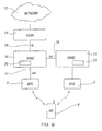
- FIG. 2 shows the hierarchy of a cellular communication system.
- the mobile station 6 is in wireless communication with one of the base stations.
- a first base station 4 is connected to a first network controller, which in Figure 2 is a serving radio network controller SRNC 10.
- SRNC 10 serving radio network controller
- more than one base station is usually connected to each controller 10 although only one is shown for clarity.
- more than one controller is also provided in a network.
- the SRNC 10 is connected to other elements of the network 12 via a suitable linking or gateway apparatus, such as a serving GPRS (General Packet radio Service) Support Node (SGSN) 14.
- GPRS General Packet radio Service
- SGSN Serving GPRS
- the SRNC 10 is arranged to control the base station, either directly or through an intermediate node (not shown).
- the controller 10 passes on data to be transmitted to the mobile station by the base station.
- the controller 10 will also receive from the base station data which the base station has received from the mobile station.
- the interface may comprise channels in both uplink and downlink directions.
- the data may be sent between the mobile station and the controller in any suitable format.
- the messages sent from the mobile stations may include information identifying the mobile station (for instance, MS ID and/or IMSI (Mobile Station Identity and/or International Mobile Subscriber Identity, respectively)).
- the cellular telecommunications system of Figure 2 includes another controller RNC 11 controlling the base station 5 of cell 3 of Figure 2 . It is, again, noted that the second controller may also control more than one base station. The second controller may also sometimes be referred to as a drift controller (DRNC).
- DRNC drift controller
- the SNRC 10 and DRNC 11 may communicate with each other over an open Iur interface 18 established between them.
- Figure 2 illustrates one possible relocation situation wherein the mobile station MS 6 or similar user equipment communicates firstly via the BTS 4 over a radio interface designated by a solid line and then switches to communicate via a new BTS 5, as designated by the dashed radio interface.
- the change from one base station to another may occur after the mobile station 6 has moved into the service or illumination area of the second base station 5.
- network optimization load balancing, hardware congestion, connection quality improvement, fault in the system or base station and so on.
- At least some of the functionalities of the network elements have to be relocated for the connection. For example, when a SRNC functionality is to be located from a first RNC to a second RNC some protocol termination points of an ongoing connection (such as RRC, RCL and/or MAC protocols) need to be changed from the first RNC to the second RNC.
- some protocol termination points of an ongoing connection such as RRC, RCL and/or MAC protocols
- the exemplifying protocol termination point is illustrated to comprise a radio resource control (RRC) protocol.
- RRC radio resource control
- MAC medium access control
- RLC radio link control
- PDCP packet data convergence protocol
- the SRNC 10 and DRNC 11 each are provided with a Radio Resource Controller functionality RRC 24 and 26, respectively.
- RRC Radio Resource Controller functionality
- the MS 6 is communication with the controller 10
- the RRC protocol has its other termination point correspondingly at the controller 10, while the other termination point is at the mobile station.
- the termination point of the RRC protocol should also be changed correspondingly.
- the new controller 11 should be provided with a similar termination point functionality using similar parameters as the previous controller had.
- Figure 3 shows further an Iur interface 18 between the DRNC 10 and the SRNC 11.
- a RNSAP Radio Network Subsystem Application Part
- a RANAP Radio Access Network Application Part; in the control plane
- L3 Layer 3
- the core network element 14 can be e.g. a mobile switching center or a serving GPRS support node.
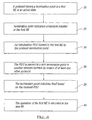
- the protocol termination point is to be moved between the termination points during an active state of the protocol between the servicing network controller and the mobile station.
- the "old" protocol termination point in the source network element produces at step 34 a special protocol data unit (PDU) containing predefined necessary protocol parameters for initialization of the second termination point before relocation of the connection.
- PDU is passed at step 36 to the new termination point with help of a second protocol.
- the second protocol is used for signaling between the different network elements or nodes.
- the passed information can be transparent to the second protocol used for the transmission of the PDU. Examples of the protocols which may be used for the transmission of the PDU will be discussed in more detail later in this specification.
- the new termination point receives the PDU and it is initialized at step 38 based on the information received from the old termination point. After the initialization procedure the termination point will be relocated at step 40 to the new network element and the operation of the system continues as before except that the protocol termination point of the active protocol is now situated in the new network element.
- an explicit protocol message will be passed between the old termination point and the new termination point of a protocol in case of relocation of the protocol termination point.
- the specified PDU (or message) is used within a protocol peer between the old and the new termination point of the protocol.
- a single protocol defines the information to be transferred between the protocol peers and the information to be transmitted within one peer. By means of this it is possible to avoid a need for defining a great number of parameters of one protocol in another protocol. For example, by the embodiment described in the following about 100 RRC parameters in the RANAP protocol are avoided.
- a radio interface L3 protocol i.e. a radio resource control; RRC
- RRC radio resource control
- the exemplifying RRC protocol is known, and is not described in more detail. It is sufficient to note that the RRC provides common controlling and signaling over the air interface between the serving RNC and the mobile station and that the RRC can be shared with circuit switched traffic and packet switched traffic.
- the control unit 20 of the first (source) RNC 10 produces the special protocol initialization unit which in this instance will be referred to as a RRC PDU.
- the RRC PDU contains all such predefined RRC parameters that have to be known by the new termination point in order to receive and continue the connection. These parameters may include information concerning e.g. one or several of the following: radio bearer(s), transport channel(s), radio link(s) and their physical channels, capability information as well as user equipment capabilities and measurements being reported by the user equipment and so on.
- the RRC PDU contains all such RRC parameters that are required by the termination point at the target RNC to start the RRC protocol in a relatively similar state and conditions that existed in the old termination point.
- the generated RRC PDU can be transferred from the first RNC to the second RNC by means of a RNSAP (Radio Network Subsystem Application Part) over an open interface Iur 18 provided between the first controller 10 and the second controller 11.
- the termination point at the second RNC receives the RRC PDU and subsequently decodes the received RRC PDU.
- the termination point 26 is initialized based on the received and decoded information. The initialization procedure can be controlled by the control unit 21.
- the PDU is firstly moved from the source RNC 10 to the core network (CN) 14 over an Iu interface 19 by a RANAP (Radio Access Network Application Part) message 'RELOCATION REQUIRED' and subsequently from the core network to the target RNC 11 by an Iu RANAP message 'RELOCATION REQUEST'.
- RANAP Radio Access Network Application Part
- the RRC PDU can be encapsulated within a message in the second protocol as there is no need for the contents of the RRC PDU to be visible for the functionality of the second protocol, such as to the RANAP or the RNSAP.
- the encapsulation of protocol messages transparently to a message of another protocol is a known technique and will thus not be discussed in more detail herein
- a protocol may "collect" required information for several protocols and generate a PDU containing required information for all or at least more than one of the protocols to be relocated.
- a separate or further protocol initialization unit PDU is used for each of the protocols to be relocated or at least some of the protocols to be relocated.
- the different protocol initialization units can be transferred between the termination point by protocols that are different to each other.
- protocol initialization unit is such that that the functionalities of the communication system may continue without disconnecting the user equipment from the communication system.
- the termination point is not relocated from a network element or node to another node but within the node.
- the relocation of some or all functionalities may also be triggered even in such conditions where the communication could continue without any relocation proceedings, e.g. in order to optimize the operation of the system or balance the load distribution in the system.
- the mobile station 6 of Figure 2 may be in communication with both controllers 10 and 11.
- a user plane communication may be enabled via the Iur interface 18 of Figure 2 , whereby the mobile station 6 within the service area of the controller 11 could still be controlled by the old servicing controller 10 via the controller 11.
- the initialization is a bidirectional process.
- the new network element may send a respond to the first element or accomplish a transmission to a further network element.
- the respond may include a message such as "unable to initialize”, “overload”, “all parameters not received” and so on.
- the first network element may modify its state and/or take some other actions towards the new termination point. For example, transmit modified parameter or parameters, or use different transmission route, or try to relocate the connection to another network element.
- the network element in question may become overloaded or a failure in the system of the network element itself may force the system to relocate at least a part of the functionalities, network optimization, load balancing and so on.
Landscapes
- Engineering & Computer Science (AREA)
- Computer Networks & Wireless Communication (AREA)
- Signal Processing (AREA)
- Mobile Radio Communication Systems (AREA)
- Communication Control (AREA)
- Burglar Alarm Systems (AREA)
- Radio Relay Systems (AREA)
- Input Circuits Of Receivers And Coupling Of Receivers And Audio Equipment (AREA)
- Data Exchanges In Wide-Area Networks (AREA)
- Stored Programmes (AREA)
- Small-Scale Networks (AREA)
Abstract
Description
- The present invention relates to relocation in a communication system and in particular, but not exclusively, to relocation of a protocol termination point.
- Communication networks typically operate in accordance with a given standard which sets out what the elements of the network are permitted to do and how that should be achieved. The communication in the networks follows predefined rules which are referred to in the following as protocols. The protocols to be used are defined in the associated standard. The protocols can be used for controlling various events and functionalities in a connection provided through the communications network. Several protocols may be simultaneously in an active state for providing control of a connection. During an ongoing i.e. active connection a protocol is having a termination point in the network element controlling the connection. For example, a protocol may have termination points in a telephone terminal and in a network controller controlling the connection.
- A communication network is a cellular radio network consisting of cells. In most cases the cell can be defined as a certain area covered by one or several base transceiver stations (BTS) serving mobile stations (MS) via a radio interface and connected to a base station subsystem (BSS). Several cells cover a larger area, and form the coverage area of a cellular radio network. The cell (or group of cells) and thus the mobile station (MS) or similar user equipment (UE) within one of the cells of the system can be controlled by a node providing controller functionality, for example by a radio network controller (RNC) or a mobile switching center (MSC). The controller can be connected further to a gateway or linking node, for example a gateway GPRS support node (GGSN) or gateway mobile switching center (GSMC), linking the cell to the other parts of the communication system and/or other communication networks, such as to a PSTN (Public Switched Telecommunications Network) or to a data network, such as to a X.25 based network or to a TCP/IP (Transmission Control Protocol/Internet Protocol) based network.
- The mobile station MS may be controlled by only one controller at time. However, the MS may also be simultaneously controlled by several controller nodes. This may occur e.g. when the cells overlap or in so called soft handoff mode, where the MS may be in communication with two base stations and those base stations may be connected to different controllers, or when one controller is controlling another controller controlling the MS. One controller of the plurality of controllers in the system can be defined as a serving (main) controller whereas the others may act as secondary controllers. The responsibility of controlling a connection between the mobile station and the network may change during an ongoing connection. It is therefore necessary to relocate at least part of functionalities associated with the connection such that the connection will not become disconnected and/or that the quality of the connection remains in an acceptable level. It is to be appreciated that in addition or as an alternative to relocating functionalities of the controller node, the functionality to be relocated may also be located in any other of the network elements, for example in the base station, base station subsystem, in the gateway and so on.
- When relocation is decided to be performed, the serving controller or another node of the communication system may initiate the necessary proceeding for replacing one or several of the network nodes with a new corresponding node or nodes.
- In case of an active i.e. ongoing connection, one of the features that should to be relocated is the state of a protocol termination point. Although it is not always necessary, in a usual case the status of the protocol termination point at the new "replacing" network element or node should be such that it may take over the functions of the old "replaced" network node. At the present the parameters which need to be transferred have to be defined also in the protocols which are used to convey the information from the old termination point to the new termination point. For example, if parameters of a Radio Resource Control (RRC) or Medium Access Control (MAC) or Radio Link Control (RLC) protocols are to be relocated in a system that would use radio network subsystem application part (RNSAP) for communication between the network controller nodes, this would mean that a lot of "external" parameters would have to be defined for the RNSAP. This would increase the complexity of the RNSAP. In addition, if several additional parameters of a protocol are to be defined for the another protocol, it makes these two different protocols very dependent on each other. The independent evolution of them would thus become more difficult to manage.
- It is an aim of the embodiments of the present invention to address one or several of the above problems.
- According to one aspect of the present invention, there is provided a method in a communication system for relocating a protocol termination point, comprising:
- defining a protocol initialization unit containing predefined information of a first termination point of a first protocol by the first protocol;
- transferring the protocol initialization unit from the first termination point to a second termination point by a second protocol; and
- initializing the second termination point based on the protocol initialization unit.
- According to another aspect of the present invention there is provided a communication system, comprising:
- a first protocol termination point;
- a second protocol termination point;
- control means for relocating a first protocol from the first protocol termination point to the second protocol termination point, said control means being arranged to form a protocol initialization unit containing predefined information of the first protocol at the first protocol termination point;
- communication path based on a second protocol between the first and the second termination points for transferring the protocol initialization unit; and
- control means for initializing the second protocol termination point based on the protocol initialization unit.
- According to a still another aspect of the present invention there is provided a network element for use in a communication network, comprising:
- a protocol termination point;
- control means for relocating a first protocol from the protocol termination point to another protocol termination point, said control means being arranged to form a protocol initialization unit containing predefined information of the first protocol at the protocol termination point; and
- interface to said other protocol termination point based on a second protocol for transferring the protocol initialization unit from the first termination point by means of the second protocol.
- According to a still another aspect of the present invention there is provided a network element for use in a communication network, comprising:
- a protocol termination point of a first protocol;
- interface to another protocol termination point for receiving a protocol initialization unit containing predefined information of the first protocol at said other termination point, wherein the interface is based on a second protocol; and
- control means for initializing the protocol termination point based on the received protocol initialization unit.
- According to a more specific embodiment, the protocol initialization unit may contain state information of the first protocol termination point.
- The first termination point may also be located at a first network element of the communication system and the second termination point may be located at a second network element of the communication system. The second network element may, upon receiving the protocol information unit, generate and transmit a response to the first network element by means of the second protocol.
- The protocol initialization unit may be encapsulated in a message transmitted between the first termination point and the second termination point. The protocol initialization unit may also be transparent for the second protocol.
- The protocol initialization unit may be transmitted via a network element of a core network of the communication system. This may be accomplished by means of a radio access network application part (RANAP) protocol. According to an embodiment, the protocol initialization unit may be transmitted directly between the termination points. This may be accomplished by means of a radio network subsystem application part (RNSAP) protocol.
- The protocol initialization unit may contain information of at least one further protocol. According to an embodiment at least one further protocol initialization unit may be defined containing predefined information of a further protocol by the further protocol, whereafter the further protocol initialization unit is transferred from the first termination point to the second termination point. The further protocol initialization unit may be transferred between the termination points by a protocol that is different to the second protocol.
- The parameters of the second termination point may be set into a state that is relatively similar to the state of parameters of the first termination point before or at the time the relocation procedure was initiated during the initialization procedure.
- The embodiments of the invention provide several advantages. One of the benefits is that a need for defining a great number of parameters of one protocol in another protocol is avoided. This provides clear benefits in updating and maintenance of the protocols.
- For better understanding of the present invention, reference will now be made by way of example to the accompanying drawings in which:
-
Figure 1 shows a schematic diagram of a cellular radio network system in which embodiments of the invention can be implemented; -
Figure 2 shows the hierarchy of various elements of the network ofFigure 1 ; -
Figure 3 shows two possible interfaces between network nodes; and -
Figure 4 is a flow chart for operation in accordance with one embodiment. - Reference will be first made to
Figure 1 in which threecells cell mobile station 6 is able to transmit signals to and receive signals from the respectivebase transceiver station cell 2 tocell 3. - The exemplifying cellular telecommunications network will be described in more detail in the following by using the terminology of a proposed Universal Mobile Telecommunications System (UMTS) standard. However, it is to be appreciated that the invention is not restricted to UMTS but can be implemented in any standard. Examples of these include, without any intention to restrict the possible communication systems to these, any of the code division multiple access (CDMA) based systems or any of the time division multiple access (TDMA) based systems or any of the frequency division multiple access (FDMA) based systems or any hybrids thereof.
- Reference is now made to
Figure 2 which shows the hierarchy of a cellular communication system. As can be seen, themobile station 6 is in wireless communication with one of the base stations. Typically a number of mobile stations will be in communication with each base station although only one mobile station is shown inFigure 2 for clarity. Afirst base station 4 is connected to a first network controller, which inFigure 2 is a serving radionetwork controller SRNC 10. Again, more than one base station is usually connected to eachcontroller 10 although only one is shown for clarity. Typically more than one controller is also provided in a network. TheSRNC 10 is connected to other elements of thenetwork 12 via a suitable linking or gateway apparatus, such as a serving GPRS (General Packet radio Service) Support Node (SGSN) 14. - The
SRNC 10 is arranged to control the base station, either directly or through an intermediate node (not shown). Thecontroller 10 passes on data to be transmitted to the mobile station by the base station. Thecontroller 10 will also receive from the base station data which the base station has received from the mobile station. The implementation of the communication between the base station, the mobile station and the controller is known, and will thus not be discussed in detail herein. It is sufficient to note that the interface may comprise channels in both uplink and downlink directions. The data may be sent between the mobile station and the controller in any suitable format. The messages sent from the mobile stations may include information identifying the mobile station (for instance, MS ID and/or IMSI (Mobile Station Identity and/or International Mobile Subscriber Identity, respectively)). - In addition to the serving controller (RNC 10), the cellular telecommunications system of
Figure 2 includes anothercontroller RNC 11 controlling thebase station 5 ofcell 3 ofFigure 2 . It is, again, noted that the second controller may also control more than one base station. The second controller may also sometimes be referred to as a drift controller (DRNC). TheSNRC 10 andDRNC 11 may communicate with each other over anopen Iur interface 18 established between them. -
Figure 2 illustrates one possible relocation situation wherein themobile station MS 6 or similar user equipment communicates firstly via theBTS 4 over a radio interface designated by a solid line and then switches to communicate via anew BTS 5, as designated by the dashed radio interface. According to one possibility the change from one base station to another may occur after themobile station 6 has moved into the service or illumination area of thesecond base station 5. However, it is to be appreciated that in addition to the movement of the mobile station, there are also other possible reasons for triggering the relocation of the connection to another base station or to another network element, such as network optimization, load balancing, hardware congestion, connection quality improvement, fault in the system or base station and so on. - In order to ensure a proper operation of the system and to avoid disconnecting a possibly ongoing call, at least some of the functionalities of the network elements have to be relocated for the connection. For example, when a SRNC functionality is to be located from a first RNC to a second RNC some protocol termination points of an ongoing connection (such as RRC, RCL and/or MAC protocols) need to be changed from the first RNC to the second RNC.
- Before explaining an embodiment for the relocation in more detail, a brief explanation will given of the protocol termination point with reference to
Figure 3 showing a block diagram of thesource RNC 10 and thetarget RNC 11. The exemplifying protocol termination point is illustrated to comprise a radio resource control (RRC) protocol. However, it is to be appreciated that the described RRC protocol is only an example, and that the embodiments can be implemented for any other protocol used for a connection in a communication system as well. These other protocols include, without any restriction to these, medium access control (MAC) protocol, radio link control (RLC) protocol and packet data convergence protocol (PDCP). - The
SRNC 10 andDRNC 11 each are provided with a Radio ResourceController functionality RRC MS 6 is communication with thecontroller 10, the RRC protocol has its other termination point correspondingly at thecontroller 10, while the other termination point is at the mobile station. However, should the controller change, the termination point of the RRC protocol should also be changed correspondingly. More precisely, thenew controller 11 should be provided with a similar termination point functionality using similar parameters as the previous controller had. These functionalities will be controlled by acontrol unit 20 at thesource controller 10 and by acontrol unit 21 at thetarget controller 11. -
Figure 3 shows further anIur interface 18 between theDRNC 10 and theSRNC 11. For example, a RNSAP (Radio Network Subsystem Application Part) protocol can be used for the direct signalling between the two RNCs. A RANAP (Radio Access Network Application Part; in the control plane) protocol can used for L3 (Layer 3) signalling over the Iu interface between the RNCs and anappropriate element 14 of thecore network 14. Thecore network element 14 can be e.g. a mobile switching center or a serving GPRS support node. - A reference will now be made to the flow chart of
Figure 4 showing in more detail an embodiment for moving the required state information of a protocol termination point from one termination point at a first network element (NE) to another termination point in a second network element. As illustrated bystep 30, the protocol termination point is to be moved between the termination points during an active state of the protocol between the servicing network controller and the mobile station. After the relocation procedures are initiated atstep 32, the "old" protocol termination point in the source network element produces at step 34 a special protocol data unit (PDU) containing predefined necessary protocol parameters for initialization of the second termination point before relocation of the connection. The PDU is passed atstep 36 to the new termination point with help of a second protocol. The second protocol is used for signaling between the different network elements or nodes. The passed information can be transparent to the second protocol used for the transmission of the PDU. Examples of the protocols which may be used for the transmission of the PDU will be discussed in more detail later in this specification. The new termination point receives the PDU and it is initialized atstep 38 based on the information received from the old termination point. After the initialization procedure the termination point will be relocated atstep 40 to the new network element and the operation of the system continues as before except that the protocol termination point of the active protocol is now situated in the new network element. - In other words, an explicit protocol message will be passed between the old termination point and the new termination point of a protocol in case of relocation of the protocol termination point. The specified PDU (or message) is used within a protocol peer between the old and the new termination point of the protocol. In a preferred embodiment a single protocol defines the information to be transferred between the protocol peers and the information to be transmitted within one peer. By means of this it is possible to avoid a need for defining a great number of parameters of one protocol in another protocol. For example, by the embodiment described in the following about 100 RRC parameters in the RANAP protocol are avoided.
- Referring again to
Figure 3 , a more detailed example of the relocation procedure will now be given in context of relocating a radio interface L3 protocol (i.e. a radio resource control; RRC) protocol from a first or source controller (e.g.RNC 10 ofFigure 3 ) to a second or target controller (e.g.RNC 11 ofFigure 3 ). The exemplifying RRC protocol is known, and is not described in more detail. It is sufficient to note that the RRC provides common controlling and signaling over the air interface between the serving RNC and the mobile station and that the RRC can be shared with circuit switched traffic and packet switched traffic. - The
control unit 20 of the first (source)RNC 10 produces the special protocol initialization unit which in this instance will be referred to as a RRC PDU. The RRC PDU contains all such predefined RRC parameters that have to be known by the new termination point in order to receive and continue the connection. These parameters may include information concerning e.g. one or several of the following: radio bearer(s), transport channel(s), radio link(s) and their physical channels, capability information as well as user equipment capabilities and measurements being reported by the user equipment and so on. According to a preferred embodiment the RRC PDU contains all such RRC parameters that are required by the termination point at the target RNC to start the RRC protocol in a relatively similar state and conditions that existed in the old termination point. - According to an embodiment the generated RRC PDU can be transferred from the first RNC to the second RNC by means of a RNSAP (Radio Network Subsystem Application Part) over an
open interface Iur 18 provided between thefirst controller 10 and thesecond controller 11. The termination point at the second RNC receives the RRC PDU and subsequently decodes the received RRC PDU. Thetermination point 26 is initialized based on the received and decoded information. The initialization procedure can be controlled by thecontrol unit 21. - According to another embodiment the PDU is firstly moved from the
source RNC 10 to the core network (CN) 14 over anIu interface 19 by a RANAP (Radio Access Network Application Part) message 'RELOCATION REQUIRED' and subsequently from the core network to thetarget RNC 11 by an Iu RANAP message 'RELOCATION REQUEST'. - The RRC PDU can be encapsulated within a message in the second protocol as there is no need for the contents of the RRC PDU to be visible for the functionality of the second protocol, such as to the RANAP or the RNSAP. The encapsulation of protocol messages transparently to a message of another protocol is a known technique and will thus not be discussed in more detail herein
- It should be appreciated that the status of any other protocol, such as the MAC protocol or RLC protocol referred to above, could also be conveyed by the RRC protocol. In more general terms, a protocol may "collect" required information for several protocols and generate a PDU containing required information for all or at least more than one of the protocols to be relocated. According to an embodiment a separate or further protocol initialization unit PDU is used for each of the protocols to be relocated or at least some of the protocols to be relocated. The different protocol initialization units can be transferred between the termination point by protocols that are different to each other.
- It should also be appreciated that some embodiments do not require an identical or relatively similar protocol termination point at the old and the new network element. However, it is preferred that the information included in the protocol initialization unit is such that that the functionalities of the communication system may continue without disconnecting the user equipment from the communication system.
- According to one possibility the termination point is not relocated from a network element or node to another node but within the node.
- It is noted that in some embodiments of the invention, the relocation of some or all functionalities may also be triggered even in such conditions where the communication could continue without any relocation proceedings, e.g. in order to optimize the operation of the system or balance the load distribution in the system. In addition, the
mobile station 6 ofFigure 2 may be in communication with bothcontrollers Iur interface 18 ofFigure 2 , whereby themobile station 6 within the service area of thecontroller 11 could still be controlled by theold servicing controller 10 via thecontroller 11. - According to a further embodiment the initialization is a bidirectional process. In other words, instead of only transmitting information from the first network element (node) to the second element, the new network element may send a respond to the first element or accomplish a transmission to a further network element. The respond may include a message such as "unable to initialize", "overload", "all parameters not received" and so on. Upon receiving the response, the first network element may modify its state and/or take some other actions towards the new termination point. For example, transmit modified parameter or parameters, or use different transmission route, or try to relocate the connection to another network element.
- It should also be appreciated that whilst embodiments of the present invention have been described in relation to a connection between the network nodes and a mobile station, embodiments of the present invention are applicable to any other suitable type of connections terminating to one node. It should also be appreciated that base stations can sometimes be referred to as node B.
- There are also other possible reasons for initiating the relocation procedure that movement of the mobile station into a new service area. For example, the network element in question may become overloaded or a failure in the system of the network element itself may force the system to relocate at least a part of the functionalities, network optimization, load balancing and so on.
- The exemplifying embodiments of the invention have discussed protocols terminated to a network controller. Embodiments of the present invention can be applicable to other network elements as well where applicable.
- It is also noted herein that while the above describes one exemplifying embodiment of the invention, there are several variations and modifications which may be made to the disclosed solution without departing from the scope of the present invention as defined in the appended claims.
Claims (15)
- A method comprising:using a first protocol to define a protocol initialization unit (20) at a first termination point of a first protocol (34), said protocol initialization unit containing predefined information pertaining to initialization of a second termination point (36) of said first protocol;transferring the protocol initialization unit from the first termination point to a second termination point by a second protocol for relocating the first protocol; wherein the first protocol is relocated due to one or more of the following: handoff of a mobile station from one service area to another service area, network optimization, load balancing, hardware congestion, connection quality improvement and network element failure.
- A method according to claim 1, wherein the protocol initialization unit (20) contains state information of the first protocol termination point.
- A method according to claim 1 or 2, wherein the first termination point is located at a first network element (10) of a communication system and the second termination point is located at a second network (11) element of the communication system.
- A method according to claim 3, wherein the second network element (11), upon receiving the protocol information unit (20), generates and transmits a response to the first network element by means of the second protocol.
- A method according to any of the preceding claims, wherein the protocol initialization unit (20) is encapsulated in a message transmitted between the first termination point and the second termination point by the second protocol.
- A method according to any of the preceding claims, wherein the protocol initialization unit is transmitted via a third network element between the termination points.
- A method according to claim 6, wherein the transmission is based on a radio access network application part (RANAP) protocol.
- A method according to any of claims 1 to 7, wherein the transmission is based on a radio network subsystem application part (RNSAP) protocol.
- A method according to any of the preceding claims, wherein the predefined information of the first protocol comprise one or several parameters of a radio resource control protocol (RRC), medium access control protocol (MAC), radio link control protocol (RLC), and/or packet data convergence protocol (PDCP).
- A network element for use in a communication network, comprising:a protocol termination point;control means for relocating a first protocol from the protocol termination point to another protocol termination point, characterized in said control means being arranged to form a protocol initialization unit (20) containing predefined information of the first protocol at the protocol termination point; andinterface to said other protocol termination point based on a second protocol for transferring the protocol initialization unit from the first termination point by means of the second protocol;wherein the first protocol is relocated due to one or more of the following: handoff of a mobile station from one service area to another service area, network optimization, load balancing, hardware congestion, connection quality improvement and network element failure.
- A network element according to claim 10, wherein the control means for relocating are arranged to encapsulate the protocol initialization unit into a message to be transmitted from the first termination point by means of the second protocol.
- A network element according to any of claims 10 to 11, wherein the protocol initialization unit contains information of at least one further protocol.
- A network element for use in a communication network, comprising:a protocol termination point of a first protocol; andan interface to another protocol termination point; characterised in being adapted to receive a protocol initialization unit containing predefined information of the first protocol at said other termination point, the protocol initialization unit being for relocating the first protocol,wherein the interface is based on a second protocol; andcontrol means for initializing the protocol termination point based on the received protocol initialization unitwherein the first protocol is relocated due to one or more of the following: handoff of a mobile station from one service area to another service area, network optimization, load balancing, hardware congestion, connection quality improvement and network element failure.
- A network element according to claim 13, wherein the network element comprises a controller of a cellular communication network.
- A method comprising:receiving at a protocol termination point from another protocol termination point by a second protocol a protocol initialization unit containing predefined information of the first protocol at said other termination point, the protocol initialization unit being for relocating the first protocol; andinitializing the protocol termination point based on the received protocol initialization unit;wherein the first protocol is relocated due to one or more of the following: handoff of a mobile station from one service area to another service area, network optimization, load balancing, hardware congestion, connection quality improvement and network element failure.
Applications Claiming Priority (2)
| Application Number | Priority Date | Filing Date | Title |
|---|---|---|---|
| GBGB9921706.9A GB9921706D0 (en) | 1999-09-14 | 1999-09-14 | Relocation in a communication system |
| EP00966045A EP1212919B1 (en) | 1999-09-14 | 2000-09-13 | Relocation in a communication system |
Related Parent Applications (1)
| Application Number | Title | Priority Date | Filing Date |
|---|---|---|---|
| EP00966045.7 Division | 2000-09-13 |
Publications (2)
| Publication Number | Publication Date |
|---|---|
| EP2237609A2 true EP2237609A2 (en) | 2010-10-06 |
| EP2237609A3 EP2237609A3 (en) | 2010-10-27 |
Family
ID=10860889
Family Applications (2)
| Application Number | Title | Priority Date | Filing Date |
|---|---|---|---|
| EP00966045A Expired - Lifetime EP1212919B1 (en) | 1999-09-14 | 2000-09-13 | Relocation in a communication system |
| EP10170344A Withdrawn EP2237609A3 (en) | 1999-09-14 | 2000-09-13 | Relocation in a cellular communication system |
Family Applications Before (1)
| Application Number | Title | Priority Date | Filing Date |
|---|---|---|---|
| EP00966045A Expired - Lifetime EP1212919B1 (en) | 1999-09-14 | 2000-09-13 | Relocation in a communication system |
Country Status (13)
| Country | Link |
|---|---|
| US (1) | US7242933B1 (en) |
| EP (2) | EP1212919B1 (en) |
| JP (1) | JP3602501B2 (en) |
| KR (1) | KR100531144B1 (en) |
| CN (1) | CN1178547C (en) |
| AT (1) | ATE480970T1 (en) |
| AU (1) | AU7657700A (en) |
| BR (1) | BR0013975B1 (en) |
| CA (1) | CA2384290C (en) |
| DE (1) | DE60044939D1 (en) |
| ES (1) | ES2348709T3 (en) |
| GB (1) | GB9921706D0 (en) |
| WO (1) | WO2001020938A1 (en) |
Families Citing this family (28)
| Publication number | Priority date | Publication date | Assignee | Title |
|---|---|---|---|---|
| JP3419386B2 (en) | 1999-09-08 | 2003-06-23 | 日本電気株式会社 | Paging system and paging method |
| DE10017062B4 (en) * | 1999-11-22 | 2015-03-05 | Ipcom Gmbh & Co. Kg | Method for operating a mobile radio network |
| US6968190B1 (en) | 1999-11-29 | 2005-11-22 | Nokia Mobile Phones, Ltd. | Transfer of optimization algorithm parameters during handover of a mobile station between radio network subsystems |
| EP1236363B1 (en) * | 1999-11-29 | 2009-08-19 | Nokia Corporation | Transfer of algorithm parameters during handover of a mobile station between radio network subsystems |
| FR2818864B1 (en) * | 2000-12-21 | 2003-04-04 | Cit Alcatel | METHOD FOR REPORTING RADIO ACCESS CAPACITY INFORMATION FROM A MOBILE STATION TO A MOBILE RADIO COMMUNICATION NETWORK IN PACKET MODE |
| SE0100475D0 (en) * | 2001-02-09 | 2001-02-09 | Ericsson Telefon Ab L M | Method and system of retransmission |
| EP1374619A1 (en) * | 2001-03-28 | 2004-01-02 | Nokia Corporation | Method for providing parameters during a change of access, cellular communications system, user equipment and network element |
| RU2242092C2 (en) | 2001-07-06 | 2004-12-10 | Самсунг Электроникс Ко., Лтд. | Method for resetting object of medium access control layer in broadband code-division multiple access communication system using high-speed downlink burst access |
| US9635540B2 (en) | 2002-03-25 | 2017-04-25 | Jeffrey D. Mullen | Systems and methods for locating cellular phones and security measures for the same |
| US7133385B2 (en) | 2002-03-29 | 2006-11-07 | Nortel Networks Limited | Network directed intersystem handoff for 1xEVD0 |
| US7177658B2 (en) | 2002-05-06 | 2007-02-13 | Qualcomm, Incorporated | Multi-media broadcast and multicast service (MBMS) in a wireless communications system |
| US6990342B2 (en) * | 2002-08-29 | 2006-01-24 | Motorola, Inx. | Method and apparatus for cell reselection within a communications system |
| JP4448036B2 (en) * | 2003-04-03 | 2010-04-07 | ユーティーシダカン(ジョングオ)ヨウシャンゴンシ | Mobility management method for user equipment and communication system therefor |
| US8804761B2 (en) * | 2003-08-21 | 2014-08-12 | Qualcomm Incorporated | Methods for seamless delivery of broadcast and multicast content across cell borders and/or between different transmission schemes and related apparatus |
| US7318187B2 (en) * | 2003-08-21 | 2008-01-08 | Qualcomm Incorporated | Outer coding methods for broadcast/multicast content and related apparatus |
| US8694869B2 (en) * | 2003-08-21 | 2014-04-08 | QUALCIMM Incorporated | Methods for forward error correction coding above a radio link control layer and related apparatus |
| WO2005027560A1 (en) | 2003-09-12 | 2005-03-24 | Ntt Docomo, Inc. | Secure intra- and inter-domain handover |
| DE60323274D1 (en) * | 2003-09-12 | 2008-10-09 | Ntt Docomo Inc | CONTEXT TRANSMISSION FOR SEAMLESS HANDOVER |
| EP1519519B1 (en) * | 2003-09-23 | 2011-04-20 | Panasonic Corporation | Protocol context transfer in a mobile communication system |
| GB0400081D0 (en) * | 2004-01-05 | 2004-02-04 | Nokia Corp | Radio network relocation |
| GB2414361B (en) * | 2004-05-17 | 2008-10-01 | Ipwireless Inc | Arrangement and method for radio network relocation |
| US7848749B2 (en) * | 2004-11-08 | 2010-12-07 | Alcatel-Lucent Usa Inc. | Method and apparatus for activating a dormant mobile unit in a distributed network |
| US20060099950A1 (en) * | 2004-11-08 | 2006-05-11 | Klein Thierry E | Method and apparatus for activating an inactive mobile unit in a distributed network |
| KR100670876B1 (en) * | 2005-05-09 | 2007-01-19 | 엘지노텔 주식회사 | How to relocate / handle RNS in WPC system |
| US7317707B2 (en) | 2005-06-02 | 2008-01-08 | Lucent Technologies Inc. | Method for seamless session transfer of a mobile station |
| US7920866B2 (en) * | 2005-07-07 | 2011-04-05 | Alcatel-Lucent Usa Inc. | Method of hard handover in a wireless communication system |
| CN101352093A (en) * | 2007-01-08 | 2009-01-21 | 华为技术有限公司 | Forward the learned state information to the moving target node |
| JP4510117B2 (en) * | 2008-06-23 | 2010-07-21 | 株式会社エヌ・ティ・ティ・ドコモ | Mobile communication method and mobile station |
Family Cites Families (22)
| Publication number | Priority date | Publication date | Assignee | Title |
|---|---|---|---|---|
| JPH0266316A (en) | 1988-07-29 | 1990-03-06 | General Electric Co <Ge> | Thrust-bearing lubricating device |
| US5189734A (en) * | 1988-11-16 | 1993-02-23 | U.S. Philips Corporation | Cellular radio system |
| US5557745A (en) * | 1990-09-04 | 1996-09-17 | Digital Equipment Corporation | Method for supporting foreign protocols across backbone network by combining and transmitting list of destinations that support second protocol in first and second areas to the third area |
| CH682867A5 (en) * | 1991-09-24 | 1993-11-30 | Ascom Tech Ag | DECT radio hand-over for cellular mobile network - reserving free second protocol control unit and data interface, simultaneously transmitting data over the paths and breaking first path protocol |
| US5917811A (en) * | 1996-05-22 | 1999-06-29 | Qualcomm Incorporated | Method and apparatus for measurement directed hard handoff in a CDMA system |
| JP3529621B2 (en) * | 1997-05-12 | 2004-05-24 | 株式会社東芝 | Router device, datagram transfer method, and communication system |
| FI105993B (en) * | 1997-08-20 | 2000-10-31 | Nokia Mobile Phones Ltd | Procedures and systems for controlling radio communication systems and radio network controllers |
| JPH11205842A (en) | 1998-01-12 | 1999-07-30 | Hitachi Ltd | Handover method between different mobile communication carrier networks, and gateway exchange |
| FI108772B (en) * | 1998-03-31 | 2002-03-15 | Nokia Corp | Procedure for controlling the connections to a mobile station |
| CA2326750C (en) * | 1998-04-03 | 2010-03-16 | Telefonaktiebolaget Lm Ericsson | Flexible radio access and resource allocation in a universal mobile telephone system (umts) |
| FI108103B (en) * | 1998-04-15 | 2001-11-15 | Nokia Mobile Phones Ltd | Mediation plan to implement protocol adaptations in a digital wireless transmission system |
| US6674765B1 (en) * | 1998-05-22 | 2004-01-06 | Lucent Technologies Inc. | Methods and apparatus for random chip delay access priority in a communications system |
| US6201969B1 (en) * | 1998-06-02 | 2001-03-13 | Lucent Technologies Inc. | Control of handoff in CDMA cellular systems |
| US6304556B1 (en) * | 1998-08-24 | 2001-10-16 | Cornell Research Foundation, Inc. | Routing and mobility management protocols for ad-hoc networks |
| US6687249B1 (en) * | 1998-08-25 | 2004-02-03 | Telefonaktiebolaget Lm Ericsson | Reconfiguring diversity legs during CN-RNC interface streamlining |
| US6725038B1 (en) * | 1999-01-26 | 2004-04-20 | Nokia Corporation | Method and apparatus for speeding up AAL2 connection setup during handover in advanced cellular networks |
| US6912230B1 (en) * | 1999-02-05 | 2005-06-28 | Tecore | Multi-protocol wireless communication apparatus and method |
| FI108326B (en) * | 1999-04-19 | 2001-12-31 | Nokia Corp | Use of the Wireless Application Protocol protocol in a packet-switched radio telecommunication system |
| US6301479B1 (en) * | 1999-07-08 | 2001-10-09 | Telefonaktiebolaget Lm Ericsson | Technique for providing a secure link in a mobile communication system |
| US6628632B1 (en) * | 1999-07-19 | 2003-09-30 | Lucent Technologies Inc. | Method and apparatus for permitting direct handoff between base stations in a wireless network |
| US6542743B1 (en) * | 1999-08-31 | 2003-04-01 | Qualcomm, Incorporated | Method and apparatus for reducing pilot search times utilizing mobile station location information |
| US6587680B1 (en) * | 1999-11-23 | 2003-07-01 | Nokia Corporation | Transfer of security association during a mobile terminal handover |
-
1999
- 1999-09-14 GB GBGB9921706.9A patent/GB9921706D0/en not_active Ceased
-
2000
- 2000-09-13 AT AT00966045T patent/ATE480970T1/en not_active IP Right Cessation
- 2000-09-13 AU AU76577/00A patent/AU7657700A/en not_active Abandoned
- 2000-09-13 DE DE60044939T patent/DE60044939D1/en not_active Expired - Lifetime
- 2000-09-13 EP EP00966045A patent/EP1212919B1/en not_active Expired - Lifetime
- 2000-09-13 CA CA002384290A patent/CA2384290C/en not_active Expired - Lifetime
- 2000-09-13 ES ES00966045T patent/ES2348709T3/en not_active Expired - Lifetime
- 2000-09-13 BR BRPI0013975-0B1A patent/BR0013975B1/en active IP Right Grant
- 2000-09-13 EP EP10170344A patent/EP2237609A3/en not_active Withdrawn
- 2000-09-13 CN CNB008128766A patent/CN1178547C/en not_active Ceased
- 2000-09-13 JP JP2001524385A patent/JP3602501B2/en not_active Expired - Lifetime
- 2000-09-13 US US10/088,452 patent/US7242933B1/en not_active Expired - Lifetime
- 2000-09-13 KR KR10-2002-7003438A patent/KR100531144B1/en not_active Expired - Lifetime
- 2000-09-13 WO PCT/EP2000/009100 patent/WO2001020938A1/en not_active Ceased
Non-Patent Citations (1)
| Title |
|---|
| None |
Also Published As
| Publication number | Publication date |
|---|---|
| KR20020040803A (en) | 2002-05-30 |
| ES2348709T3 (en) | 2010-12-13 |
| GB9921706D0 (en) | 1999-11-17 |
| AU7657700A (en) | 2001-04-17 |
| EP2237609A3 (en) | 2010-10-27 |
| US7242933B1 (en) | 2007-07-10 |
| CA2384290A1 (en) | 2001-03-22 |
| WO2001020938A1 (en) | 2001-03-22 |
| JP3602501B2 (en) | 2004-12-15 |
| ATE480970T1 (en) | 2010-09-15 |
| CN1178547C (en) | 2004-12-01 |
| EP1212919A1 (en) | 2002-06-12 |
| BR0013975B1 (en) | 2013-08-27 |
| DE60044939D1 (en) | 2010-10-21 |
| JP2003509981A (en) | 2003-03-11 |
| CN1373979A (en) | 2002-10-09 |
| KR100531144B1 (en) | 2005-11-28 |
| BR0013975A (en) | 2002-07-02 |
| EP1212919B1 (en) | 2010-09-08 |
| CA2384290C (en) | 2005-11-15 |
Similar Documents
| Publication | Publication Date | Title |
|---|---|---|
| EP1212919B1 (en) | Relocation in a communication system | |
| EP1360864B1 (en) | Paging method and system for a radio access network | |
| EP1657862B1 (en) | Centralized dynamical resource reservation method based on the exchange of service specific capacity settings in a multi-RAT network | |
| EP1362496B1 (en) | A communication system comprising a plurality of communication networks | |
| JP4268634B2 (en) | Method and system for integrating resource allocation between TDD and FDD in a wireless communication system | |
| US6721566B2 (en) | Cell update in a cellular communications system | |
| EP1679912A2 (en) | Radio access network apparatus and mobile communication system using the same | |
| US7664265B2 (en) | Controlling communications between stations | |
| KR100378895B1 (en) | RAU optimisation in standby state | |
| US6765890B1 (en) | RAU optimization for UMTS URA connected state | |
| EP2064906B1 (en) | Method for recovering connectivity in the event of a failure in a radio communications system and controlling node thereof | |
| KR20010073045A (en) | Cdma transmission of packet-switched data | |
| KR20020003824A (en) | A method for providing multiple points of connectivity to subscribers of wireless communication networks | |
| EP1410664A1 (en) | Ip-based gsm and umts system | |
| EP1705935A2 (en) | Improved OpenRAN architecture for Radio Network Controller, Mobile Communication System and method of controlling Radio Base Station device | |
| GB2371179A (en) | Cell updates in a UMTS terrestrial radio access network | |
| EP1702490B1 (en) | Radio network relocation | |
| US20060023660A1 (en) | Location structure configuration training method for use in a cellular mobile communication system | |
| US20060080387A1 (en) | Communications network | |
| GB2382273A (en) | Abnormal release recovery in a UTRAN of a UMTS network |
Legal Events
| Date | Code | Title | Description |
|---|---|---|---|
| PUAI | Public reference made under article 153(3) epc to a published international application that has entered the european phase |
Free format text: ORIGINAL CODE: 0009012 |
|
| PUAL | Search report despatched |
Free format text: ORIGINAL CODE: 0009013 |
|
| AC | Divisional application: reference to earlier application |
Ref document number: 1212919 Country of ref document: EP Kind code of ref document: P |
|
| AK | Designated contracting states |
Kind code of ref document: A2 Designated state(s): AT BE CH CY DE DK ES FI FR GB GR IE IT LI LU MC NL PT SE |
|
| RTI1 | Title (correction) |
Free format text: RELOCATION IN A CELLULAR COMMUNICATION SYSTEM |
|
| AK | Designated contracting states |
Kind code of ref document: A3 Designated state(s): AT BE CH CY DE DK ES FI FR GB GR IE IT LI LU MC NL PT SE |
|
| RTI1 | Title (correction) |
Free format text: RELOCATION IN A CELLULAR COMMUNICATION SYSTEM |
|
| RIN1 | Information on inventor provided before grant (corrected) |
Inventor name: AHMAVAARA, KALLE |
|
| STAA | Information on the status of an ep patent application or granted ep patent |
Free format text: STATUS: THE APPLICATION IS DEEMED TO BE WITHDRAWN |
|
| 18D | Application deemed to be withdrawn |
Effective date: 20110428 |