EP2237482A1 - Method for preparing a data frame for checking continuity defaults in a Passive Optical Network (PON) - Google Patents
Method for preparing a data frame for checking continuity defaults in a Passive Optical Network (PON) Download PDFInfo
- Publication number
- EP2237482A1 EP2237482A1 EP09305278A EP09305278A EP2237482A1 EP 2237482 A1 EP2237482 A1 EP 2237482A1 EP 09305278 A EP09305278 A EP 09305278A EP 09305278 A EP09305278 A EP 09305278A EP 2237482 A1 EP2237482 A1 EP 2237482A1
- Authority
- EP
- European Patent Office
- Prior art keywords
- quality
- service
- emitter
- marker
- receiver
- Prior art date
- Legal status (The legal status is an assumption and is not a legal conclusion. Google has not performed a legal analysis and makes no representation as to the accuracy of the status listed.)
- Granted
Links
Images




Classifications
-
- H—ELECTRICITY
- H04—ELECTRIC COMMUNICATION TECHNIQUE
- H04L—TRANSMISSION OF DIGITAL INFORMATION, e.g. TELEGRAPHIC COMMUNICATION
- H04L43/00—Arrangements for monitoring or testing data switching networks
- H04L43/08—Monitoring or testing based on specific metrics, e.g. QoS, energy consumption or environmental parameters
- H04L43/0823—Errors, e.g. transmission errors
- H04L43/0829—Packet loss
Definitions
- the present invention relates to a method for checking continuity defaults in a transmission network, in particular a Passive Optical Network (PON), and a transmission network wherein the method is implemented.
- PON Passive Optical Network
- Passive Optical Networks are well known as being one among the two architectures of the access part of optical networks. This architecture is also called Point to Multipoint architecture.
- Protection mechanisms for protecting a Passive Optical Network are necessary to ensure a high quality of service, in particular a good availability of services for some users who subscribed such a quality of service with protection.
- One approach is to implement protection mechanisms as defined by International Telecommunication Union - Telecommunication (ITU-T) recommendations which are defined at a rather low level by embedding specific data frames inside the Passive Optical Network protocol.
- This protection mechanism well suited to protect Passive Optical Networks requires that the Passive Optical Network equipments, for example Optical Network Units (ONUs) and Optical Line Terminations (OLTs), incorporate specific electronic parts. It will be needed to develop either two lines of products for unprotected equipments and protected equipments, or a single line of products wherein all equipments contain the implemented protection mechanism. In both cases this leads to increase hardware complexity of the equipments (ONUs and OLTs) and accordingly the cost of the Passive Optical Network.
- ITU-T International Telecommunication Union - Telecommunication
- a second approach is to implement the protection function outside the PON equipments by using an Ethernet mechanism built at the second level and installed only for the protected equipments.
- This Ethernet mechanism is defined in the ITU-T recommendation G.8031/Y. 1342 (Ethernet Protection Switching) and in the ITU-T recommendation Y 1731 (OAM Functions and Mechanisms for Ethernet base Network).
- CCM data entities CCM standing for Continuity Check Message
- the number of user data entities received is checked against a reference count contained in the CCM data entities.
- Passive Optical Network systems have some Quality of Service (QoS) management mechanism which can reorder the sequencing of the user data entities.
- QoS Quality of Service
- the Ethernet mechanism is not applicable. Because of the reordering, some or all user data entities previously embedded within two CCM data entities can arrive before or after their embedding CCM data entities.
- the technical problem is to determine a method for checking continuity of a Passive Optical Network implemented outside the conventional Passive Optical Network equipments (Optical Network Units and Optical Line Terminations) that operates regardless of the reordering performed on user data entities by the Quality of Service management mechanism.
- the invention accordingly relates to a method for preparing and transmitting a data frame in a transmission network comprising an emitter, a transmission line and a receiver connected in series, characterized in that the method comprises the following steps consisting of subsequently:
- the method for preparing and transmitting a data frame comprises one or more of the following characteristics:
- the invention also relates to a method for checking continuity in a transmission network comprising an emitter, a transmission line and a receiver connected in series and a receiving user counter (UCR), characterized in that it comprises the steps consisting of :
- the method for checking continuity comprises one or more of the following characteristics :
- the invention also relates to a transmission network comprising an emitter protection unit, an emitter, a transmission line and a receiver connected in series, characterized in that the protection emitter unit is able to provide at least one set of subsequent data packets cut amongst data packets serially arranged (Q(i)), each set being empty or formed by at least one packet (Q(i, g)) and each packet (Q(i, g)) of a same set being associated to a Quality of Service (QoS(i)) among a set of at least two Quality of Service (QoS), the emitter protection unit is able, for each predetermined set, to provide a counting marker for determining the number of data packets of the set (159)and at least two Quality of Service markers corresponding respectively to a different Quality of Service (QoS), and the emitter is able to transmit the packets Q(i, g, QoS) of the set if any having a same quality of service (QoS) followed by the corresponding quality of service marker and to transmit
- the transmission network comprises one or more of the following characteristics :
- the invention also relates also to a computer program product comprising all the necessary code instructions to carry out the steps of the method as defined here above when the instructions are executed by a processor.
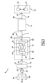
- a transmission system 2 comprises at least one emitter 4, only one emitter 4 being here shown, and at least one receiver 6, only one receiver 6 being here shown, the emitter 4 and the receiver 6 being connected between each other by a physical link 8 or transmission line.
- the transmission system 2 also comprises a protection emitter unit 10 and a protection receiver unit 12 connected respectively to the emitter 4 and the receiver 6 through respective data links 14 and 16.
- the protection emitter unit 10 has an output terminal port 18 connected to the emitter 4 and an input terminal port 20.
- the input terminal port 20 of the protection emitter unit 10 is for example connected to the single output of a switching unit 22 connected at input to three communication data user terminals 24, 26, 28.
- the protection emitter unit 10 is able to receive, here from the switching unit 22, a stream of user data packets Q(i) arranged in series, i being an integer for identifying one user data packet.
- the protection emitter 10 is able to cut the stream of user data packets Q(i) into several sets S(g) of user data packets Q(i,g), each set S(g) being identified by a different group identifier g.
- the cutting depends either on a predetermined volume of data received at its input terminal 20 or on a predetermined period of time or both.
- the protection emitter unit 10 is also able to add signalling data before, after or between the user data packets Q(i,g) of a same set S(g) and to send to the emitter 4 these user data packets Q(i, g) forming a set S(g) with signalling data added therefore.
- Each set S(g) of user data packets Q(i,g) comprises user data packets Q(i,g, QoS), each user data packet being associated to a level of Quality of Service identified by QoS.
- Each user data packet refers to a service such as for example a video service, a phone call service, or an interactive data exchange service.
- a type of service is related to a specific Quality of Service (QoS), and more specifically due to real time transmission requirements, some services as video data packets, phone data packets have a higher level of priority for transmission than in the case of a simple file data transfer which can afford greater variations of time delay between subsequent packets.
- QoS Quality of Service
- the quality of service is limited to a level of priority but the concept of quality of service is broader in general case.
- a set S(g) of user data packets is either empty or comprises at least one user data Q(i,g,p) packet subsequently transmitted with one or several different priority levels p.
- the protection emitter unit 10 is able to transmit to the emitter 4 the cut set S(g) of user data packets with their corresponding added signalling data.
- the protection receiver unit 12 has an input terminal 30 connected to the receiver 6 and is able to receive the user data packets Q(i) and the signalling data transmitted by the protection emitter unit 10 through the emitter 4 and the receiver 6.
- the protection receiver unit 12 comprises processing means, for example a microprocessor 32, with a memory 34, for processing the data packets Q(i) and the signalling data.
- processing means for example a microprocessor 32, with a memory 34, for processing the data packets Q(i) and the signalling data.
- the receiver 6 has a first terminal 36 connected to the emitter 4 through the transmission line 8 and a second terminal 38 connected to the terminal 30 of the protection receiver unit 12.
- the emitter 4 has a first terminal 40 connected to the terminal 18 of the protection emitter unit 10 and a second terminal 42 connected to the first terminal 36 of the receiver 6.
- the emitter 4 comprises a data order rearrangement unit 44 connected by an input 46 to the first terminal 40 of the emitter and by an output 48 to second terminal 42 of the emitter.
- the data order rearrangement unit 44 is able to receive from the protection emitter unit 10 the user data packets Q(i,g,p) cut into sets S(g) with the corresponding added signalling data and to rearrange the data order according to their associated quality of service QoS.
- the data order rearrangement unit 44 in this example is limited to rearrange the data according levels of priority and is therefore a priority management unit.
- the data order rearrangement unit 44 comprises a de-multiplexing unit 50, connected to the first terminal 46 and able to de-multiplex received data from the emitter protection unit 10 into a set of buffers 52, 54, 56, here three buffers, that constitute different queuing files with a First in First out data structure and a level of priority p assigned here amongst three levels of priority ranging from 1 to 3.
- the first queuing file buffer 52 shown at a bottom level in the Figure 1 is assigned to the lower level of priority equal to 1.
- the second queuing file buffer 54 shown at an intermediate level in the Figure 1 is assigned to an intermediate level of priority equal to 2.
- the third queuing file buffer 56 shown at a top level in the Figure 1 is assigned to a high level of priority equal to 3.
- the level of priority 3 is the highest level of priority and is the maximum number among all the priority level integers.
- the maximum number is designated in the general case by pmax.
- the data order rearrangement unit 44 also comprises a multiplexing unit 58 connected at its input to each respective output of the queuing file buffers 52, 54, 56 and at its output to the second terminal 48 of the data order rearrangement unit 44.
- the multiplexing unit 58 is able to rearrange according a decreasing order of priority level the data by outputting all the data contained in one buffer, the buffer having a higher level of priority being unloaded first.
- the third queuing file buffer 56 is emptied first followed by the second queuing file buffer 54 and lastly the first queuing file buffer 52 is emptied.
- the data order rearrangement unit 44 is able to carry out more complex rearrangement algorithm based on different parameters than the priority levels, and is different from a server with queuing files in parallel.
- the data order rearrangement unit is a server with queuing files in parallel, a different priority level being assigned to each queuing file, each file being unloaded at a respective different rate proportional to its assigned priority level, the number of packets involved depending on the throughput at the output.
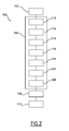
- the method for checking continuity comprises a set 100 of steps.
- the set 100 of steps comprises an initialization step 102, a set 104 of subsequent steps for preparing a data frame outputted at the output 42 of the emitter 4, a checking continuity step 108 comprising at least one reporting step of continuity default status on a regularly time basis, a step 110 for activating a switch over to a redundant transmission path in case of a detected continuity default.
- the set 104 comprises the subsequent steps 112, 114, 116, 118, 122, 124, 126.
- a first predetermined reference number contained is set in an emitting user counter UCE and a second predetermined reference number is set in receiving user counter UCR.
- the emitting user counter UCE and the receiving user counter UCR are set at a same value, for example zero,
- the emitter protection unit 10 cuts on a periodic time basis or a data volume basis the received user data packets Q(i) if any into sets S(g) of subsequent data packets Q(i,g), each cut set S(g) being empty or formed by at least one packet Q(i, g) and each packet Q(i, g) of a same set S(g) is associated to a priority level p amongst a set of at least two priority levels.
- the emitter protection unit 10 provides a counting marker C(g) containing the total number of user data packets of the set S(g) counted by the emitting user counter UCE.
- the emitter protection unit 10 forms a group G(g) of signalling elements associated to the current set S(g) and comprising the counting marker C(g) followed by at least two priority level markers M(g, p), each priority level marker M(g, p) containing the same group identifier g and a respective associated priority level p, the highest priority level being equal to the integer pmax.
- the emitter protection unit 10 transmits the set S(g) of user data packets Q(i, g, p) with its following signalling data G(g) to the emitter 4.
- the data order rearrangement unit 44 For each set S(g) followed by its corresponding group G(g), the data order rearrangement unit 44 carries out the following set of steps.
- the de-multiplexing unit 50 inputs into the queuing file buffer F(pmax) with highest priority level pmax, firstly the counting marker C(g) and lastly the level priority marker M(g, pmax) corresponding to the set S(g) and to the highest level of priority.
- the de-multiplexing unit 50 inputs into the respective queuing file buffer F(p) corresponding to the priority level p, firstly the packets Q(i,g, p) of the set S(g)) if any with priority p without changing their sequencing order exhibited at the input of the de-multiplexing unit 50 and lastly the level priority marker M(g, p).
- the multiplexing unit 58 multiplexes the serially arranged data contained in the queuing files buffer F(p) according to the decreasing order of the priority levels p.
- the data from the buffer with the highest priority level are outputted firstly, followed by the data from the buffers ranged according decreasing order of the related priority levels and transmitted into the transmission line 8.
- an outputted frame Fr(g) is obtained.
- an example of the processing of a set S(g) is shown at three stages 152, 154, 156 corresponding for a first stage 152 to the data observed at the output 18 of the protection emitter unit 10 after the step 118, for a second stage 154 to the data observed at the queuing file buffers level after the step 124, for a third stage 156 to the data observed at the output terminal 42 of the emitter 4 after the step 126.
- the group identifier g is the identifier assigned to the current set group 159, G(g) corresponding to the current set S(g).
- a first data frame 158 of data arranged in series comprises a current set 159, or S(g) of three subsequent user data packets 160, 162,164 preceded by a previous group 166, G(g-1), corresponding to a previous set S(g-1) partially shown in the figure 3 , and followed by a group 168, G(g) corresponding to the current set 159 or S(g).
- the first data frame 158 also comprises as an example two extra user data packets 170, 172 that do not belong to the current set 159, the first one 170 located before the previous group 166 possibly belonging to the previous set S(g-1))and the second one 172 located after the current group 168 possibly belonging to a following set S(g+1).
- the current set 159 of data exhibits in this example the user data packet 164 associated to an intermediate priority level equal to 2 and the two user data packets 160, 162 associated to a lowest priority level equal to 1.
- the previous group 166, G(g-1) comprises a counting marker 174 preceded by three priority level markers 176, 178, 180, the first priority level marker 176 corresponding to the priority level equal to 1, the second priority level marker 178 corresponding to the priority level equal to 2, the third priority level marker 180 corresponding to the priority level equal to 3.
- the current group 168, or G(g) comprises a counting marker 182 or C(g) followed by three priority level markers 184, 186, 188, the first priority level marker 184 or M(g, 1) corresponding to the priority level equal to 1, the second priority level marker 186 or M(g, 2) corresponding to the priority level equal to 2, the third priority level marker 188 M(g, 3) corresponding to the priority level equal to 3.
- the counting marker 174 and each priority level marker 176, 178, 180 contain the same group identifier g-1 and the emitter identifier e of the emitter 4.
- the counting marker 182 and each priority level marker 184, 186, 188 contain the same group identifier g and the emitter identifier e of the emitter 4.
- a second data frame 190 corresponding to the first data frame 158 is distributed in parallel into three queuing files data frames 192, 194, 196, the queuing file data frames 192, 194, 196 being respectively contained within the queuing file buffers 52, 54, 56 of Figure 1 .
- the extra user data packet 170, the following first priority level marker 176, the following two user data packets 160, 162 of the group 159, the following first priority level marker 184, the following extra user data packet 172 are arranged in series.
- the following priority level marker 178 corresponding to the previous set S(g-1), the following user data packet 164 of the group 159 or G(g) with a level priority equal to 2, the following priority level marker 186 corresponding to the group 159 are arranged in series.
- the third queuing file data frame 196 corresponding to the highest priority level 3 no user data packet are contained in this example.
- the third queuing file data frame may contain user data packets.
- the third queuing file data frame contains only the counting marker 174, C(g-1) corresponding to the previous set S(g-1) followed by the third priority level marker 180, M(g-1, 3) corresponding to the set S(g-1) and then the counting marker 182, C(g) followed by the third priority level marker 188, M(g, 3) corresponding to the current set 159.
- the third data frame 198 comprises the data of the second data frame 190 arranged in series at the output 42 of the emitter 4.
- the third data frame 198 comprises arranged in series, the counting marker 174, C(g-1), the following third priority level marker 180 or M(3, g-1), the following counting marker 182, C(g), the following third priority level marker 188, M(3,g), the following second priority level marker 178, M(2,g-1), the following user data packet 164 with intermediate priority level equal to 2, the following second priority level marker 186, M(2,g), the following first extra user data packet 170, the following first priority level marker 176, M(1,g-1), the following two user data packets 162, 160 of the set 159 with the lowest priority level 1, the following first priority level marker 184, M(1, g) and the following second extra user data packet 172.
- the method described in Figure 2 and Figure 3 is carried out in a transmission system comprising at least two emitters, each emitter being identified by its own emitter identifier e .
- the checking continuity step 108 comprises a set of steps arranged in five loops 202, 204, 206, 208, 210.
- the step 108 is carried out for at least one emitter 4, each emitter being identified by its own different identifier e .
- the protection receiver unit 12 measures for each emitter 4 identified by e , the elapsed time since the last corresponding group G(g-1, e) reception and compares the measured elapsed time with a predetermined timeout value Tout.
- a transmission problem related to a continuity default between the emitter 4 identified by e and the receiver is indicated to a protection switch over control unit for further action namely a switch to a backup link.
- the protection receiver unit 12 checks whether new available data have been received.
- step 108 continues by a jumping to the step 214.
- the first loop comprises the steps 214 and 218.
- the received data are stored in the memory 34 and classified amongst the user data packets and the elements, the elements comprising the respective counting marker and the priority level markers related to each emitter identified by e .
- the protection receiver unit 12 searches for each emitter 4 identified by e whether the last available data received is a last element of the group G(g, e), namely one marker among the priority level markers M(p, g, e) or the counting marker C(g, e) related to the group G(g, e) containing the corresponding identifier g and related to the emitter identifier e .
- step 108 continues to a following step 224 of the second loop 204, wherein the receiver protection unit 12 checks whether the last received available data is an element of a group G(g, e).
- the protection receiver unit 12 determines the group identifier g of the element and stores the element in a group class corresponding to the identifier g and the emitter identifier e . Then the method jumps to the step 214.
- the second loop 204 comprises the steps 214, 218, 220, 222, 224 and 226.
- the protection receiver unit 12 checks whether the last received available data is a user data packet.
- step 108 continues to the step 214.
- the third loop comprises the steps 214, 218, 220, 222, 224, 226 and 228.
- the receiving user counter UCR is incremented by one unity.
- the step 108 continues to a second continuity testing step 232 of the fifth loop 210 embedding the fourth loop 208.
- the protection receiver unit 12 determines the total number of user data packets belonging to the set S(g, e) associated to the emitter identified by e from the counting marker C(g, e). Then, In the same step 232, the protection receiver unit 12 calculates the difference between the current value of the receiving user data counter UCR and the total number of user data packets belonging to the set S(g, e). In the same step 232, a test is performed on the sign of this difference.
- the receiving user counter UCR is updated by inputting the calculated difference at step 232 as the updated value.
- step 108 continues by jumping to step 214.
- the fifth loop 210 comprises the steps 214, 218, 220, 222, 232, 236.
- each priority level marker namely a posterior position
- a posterior position enables to track the actual transmission of the user data packets belonging to a same group and emitted by a same emitter regardless of a priority rearrangement of the packets and to count these packets as correctly transmitted through the line to the receiver upon the corresponding counter regardless of its position in the flow of data received.
- continuity checking is performed not only regardless of any priority rearrangement performed by the emitter but also regardless of any extra data packets inserted during transmission.
- the checking continuity process does not need the stringent and complex requirements of a data or data packet integrity monitoring but is rather a fuzzy-like control of the flow of data expected to be transmitted through the physical link or transmission line.
- the transmission system 302 comprises at least one emitter 304, only one emitter 304 being here shown and at least one receiver 306, only one receiver 306 being here shown, the emitter 304 and the receiver 306 being connected between each other by a physical link 308.
- the transmission system 302 also comprises a protection emitter unit 310 and a protection receiver unit 312 connected respectively to the emitter 304 and the receiver 306 through one bidirectional data link 314 and tree bidirectional links 316, 317, 318.
- the emitter 304 has the same structure as the emitter 4 of Figure 1 .
- the receiver 306 is based on the receiver 6 of Figure 1 and further comprises within a single unit 320 a receiver forward link de-multiplexer unit and a receiver return link multiplexer unit.
- the receiver 306 has a receiver input terminal 322 used both for a forward link and a return link and three receiver output terminals 324, 326, 328, each received output terminals 324, 326, 328 being respectively used for a different bidirectional link 316, 317, 318.
- Each receiver output terminal 324, 326, 328 is associated to a different parameter ⁇ 1, ⁇ 2, ⁇ 3.
- the output terminals 324, 326, 328 correspond respectively to the parameters ⁇ 1, ⁇ 2, ⁇ 3.
- the parameters ⁇ 1, ⁇ 2, ⁇ 3 are for example different services, or different qualities of service or destination addresses of different data terminals.
- the protection emitter unit 310 and the emitter 304 are able to carry out the same steps 112, 114, 116, 118, 120, 122, 124, 126 of Figure 2 .
- the protection emitter unit 310 comprises a processing unit for example a microprocessor 330 with a memory 332 able to perform the same tasks as ones performed by the receiver protection unit 12 of Figure 1 .
- the protection receiver unit 312 comprises three separate protection receiver subunits 334, 336, 338 not interconnected having one respective terminal port 340, 342, 344 used respectively for one bidirectional link 316, 317, 318 and respectively connected to one receiver output terminal 324, 326, 328.
- Each terminal port 340, 342, 344 of the protection receiver unit 312 is able to receive separately the data, such as user data packets, quality of service markers and counting markers, corresponding to a same respective parameter ⁇ 1, ⁇ 2, ⁇ 3.
- the protection receiver unit 312 is able to send back to the protection emitter 310 through a set of return links all the markers and user data packets sent previously from the protection emitter unit 310.
- the protection receiver unit 312 is able to, after receiving at each subunit 334, 336, 338 the user data packets and markers associated to one respective different parameter ⁇ 1, ⁇ 2, ⁇ 3, to determine separately the values of different user data partial counters UCR( ⁇ 1), UCR( ⁇ 2), UCR( ⁇ 2) by counting and updating for each partial receiving user counter UCR( ⁇ 1), UCR( ⁇ 2), UCR( ⁇ 2) the number of user data packets received by the protection receiver unit 312 and related to a same parameter ⁇ 1, ⁇ 2, ⁇ 3.
- Each subunit 334, 336, 338 of the protection receiver unit 312 is also able to send back to the emitter protection unit 310 the values of all the receiving user partial counter UCR( ⁇ 1), UCR( ⁇ 2), UCR( ⁇ 2).
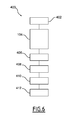
- the method carried out by the second embodiment of the transmission system of Figure 5 comprises a set 400 of subsequent steps.
- the emitting user counter UCE and the receiving user counter UCR implemented within the emitter protection unit 310 are set at a same value equal here to zero.
- the emitting user counter UCE is the same counter as one implemented in the emitter protection unit 10 of Figure 1 .
- the emitting user counter counts for one associated emitter 304 the data of a same cut set S(g, e) and is set again to zero at the start of a following set S(g, e).
- the receiving user counter UCR is the same counter as one implemented in the receiver protection unit 12 of Figure 1 .
- the receiving user counter UCR counts the user data packets sent back from the protection receiver unit 12 through the receiver 306 and the emitter 304.
- the received data at the input terminal 322 of the receiver 306 are de-multiplexed into different data streams related to a different parameter ⁇ 1, ⁇ 2, ⁇ 3.
- the respective data streams are outputted at the output terminals 324, 326, 328 of the receiver 306 and transmitted to the protection receiver unit 312.
- a subsequent step 408 all the data, including markers and user data packets received by the protection receiver unit 312 are sent back to the protection emitter unit 310 through the receiver 306 and the emitter 304 regardless of their receiving subunits 334, 336, 338.
- a step 410 the data received from the protection receiver unit 312 are processed by the emitter protection unit 310 in the same way as described by the steps for continuity checking described in figure 4 .
- the method carried out by the variant of the second embodiment of the transmission system of Figure 5 comprises a set 420 of subsequent steps.
- the emitting user counter UCE implemented within the receiver protection unit 310, the receiving user counter UCR implemented within the emitter protection unit 310, and the three receiving user data partial counters UCR(1), UCR(2), UCR(3) implemented within the receiver protection unit 312 are set at a same value equal here to zero.
- the protection receiver unit 312 after receiving at each subunit 334, 336, 338 the user data packets and markers associated to one different parameter ⁇ 1, ⁇ 2, ⁇ 3, determines separately the values of the different user data partial counters UCR( ⁇ 1), UCR( ⁇ 2), UCR( ⁇ 3).
- Each user data partial counter UCR( ⁇ 1), UCR( ⁇ 2), UCR( ⁇ 3) is incremented when its corresponding subunit level 334, 336, 338 receives a new user data packet and is reset to zero when a Quality of Service marker is received by the corresponding subunit level 334, 336, 338.
- the protection receiver unit 312 sends back to the emitter protection unit 310 through the receiver 306 and the emitter 304 the value of the user data partial counter reached before its reset to zero when a quality of service marker has been detected in its corresponding subunit, every quality of service marker and every counting marker when received but not the user data packets.
- the data received from the protection receiver unit 312 are processed by the emitter protection unit 310.
- step 428 the same steps 214, 216, 218 as ones of Figure 4 are carried out by the emitter protection unit 310.
- the received data are stored in the memory 332 and classified amongst the user data partial counter value and the elements, the elements comprising the respective counting marker and the priority level markers related to each emitter identified by e .
- the current value of the receiving user data counter UCR is updated by adding the received value of the user data partial counter.
- step 428 similar steps as the steps 222, 224, 226 of Figure 4 are carried out but by the protection emitter unit 310.
- the protection emitter unit 310 determines the total number of user data packets belonging to the set S(g, e) associated to the emitter 304 identified by e from the counting marker C(g, e).
- the protection emitter unit 310 calculates the difference between the current value of the receiving user data counter UCR and the total number of user data packets belonging to the set S(g, e). Then, in the same step 428, a test is performed on the sign of this difference.
- the receiving user counter UCR is updated by inputting the calculated difference as the updated value of UCR, and the steps continues again by jumping to the step similar to step 214 of Figure 4 .
- step 412 activating of a switch over to a redundant transmission path is carried out in a step 412 similar to step 110 of Figure 2 .
- the transmission network is in particular a Passive Optical Network 500.
- the Passive Optical Network 500 comprises two optical sub-networks 502, 504, a first optical sub-network 502 called working sub-network for nominally working, the second optical sub-network 504 called protection sub-network serving as redundant back up sub-network when a transmission default occurred on a fibre link of the working sub-network 502.
- the Passive Optical Network 500 also comprises several protection units.
- the working optical sub-network 502 comprises a working Optical Line Termination 506 (OLT) upwardly connected through a protection unit to a switch not shown in the Figure 8 and belonging to a high rate optical networking infrastructure not shown.
- OLT working Optical Line Termination 506
- the working optical sub-network 502 also comprises a working optical splitter 508 upwardly connected to the working Optical Line Termination 506 (OLT) through a working dedicated optical fibre 510.
- OLT working Optical Line Termination 506
- the working optical sub-network 502 also comprises several working Optical Network Units, here three 512, 514, 516, each one being located inside a different customer premise or user and being connected to the same working splitter 508 through respective dedicated fibres 518, 520, 522.
- the first, second, third working Optical Network Units 512, 514, 516 respectively associated to a first, second, third user share the same optical fibre 510 from the working Optical Line termination 506 to the working splitter 508.
- uplink and downlink data are transmitted simultaneously using two distinct wavelengths of a laser.
- Such a downlink/uplink access scheme is referred as wavelength duplex access.
- a time slot is allocated repeatedly to each user of a cluster, wherein transmission of data is enabled.
- Time slots are configured into a frame in such a way to avoid simultaneous transmission which could collide.
- Such an uplink access scheme from the network terminals to the OLT is conventionally called a Time Division Multiplexing Access (TDMA).
- TDMA Time Division Multiplexing Access
- the protection optical sub-network 504 comprises a protection Optical Line Termination 526 (OLT) also upwardly connected through a protection unit to a switch not shown in the Figure 8 and belonging to a high rate optical networking infrastructure.
- OLT protection Optical Line Termination 526
- the protection optical sub-network 504 also comprises a working optical splitter 528 upwardly connected to the working Optical Line Termination 526 (OLT) through a working dedicated optical fibre 530.
- OLT working Optical Line Termination 526
- the protection optical sub-network 504 also comprises several protection Optical Network Units, here three 532, 534, 536, each one being respectively paired with one different working Optical Network Unit 512, 514, 516 and being connected to the same protection splitter 528 through respective dedicated fibres 538, 540, 542.
- the first, second, third protection Optical Network Units 532, 534, 536 respectively associated to the first, second, third user share the same optical fibre 530 from the protection Optical Line termination 526 to the working splitter 528.
- each working Optical Network Unit 512, 514, 516 is considered as an emitter 4 of the Figure 1 whereas the working Optical Line termination 506 is considered as a receiver 6 of Figure 1 .
- the working Optical Line Termination 506 is considered as an emitter 4, 304 of the Figure 1 and the Figure 5 whereas anyone among the working Optical Network Units 512, 514, 516 is considered as a receiver 6, 306 of the Figure 1 and the Figure 5 .
- ONUs' protection units 550, 552, 554 are connected to each Optical Network Unit 512, 532, 514, 534, 516, 536.
- the first protection unit 550 is respectively connected to the first working Optical Network Unit 512 and to the first protection Optical Network Unit 532 though the bidirectional links 556 and 558.
- the second protection unit 552 is respectively connected to the second working Optical Network Unit 514 and to the second protection Optical Network Unit 534 though the bidirectional links 560 and 562.
- the third protection unit 554 is respectively connected to the third working Optical Network Unit 516 and to the third protection Optical Network Unit 536 though the bidirectional links 564 and 566.
- An OLT's protection unit 570 is connected to the working Optical Line Termination 506 and to the protection Line Termination 526 through the bidirectional links 572, 574.
- Each protection unit 550, 552, 554, 570 comprises a protection emitter unit and a protection receiver unit as defined in Figure 1 and Figure 2 able to carry out the steps for checking a default continuity of a fibre either in uplink direction or in downlink direction.
- each group G(g) comprises for each quality of service and for each receiver a corresponding quality of service marker.
- the number of quality of service markers of a group G(g) is therefore equal to the number of quality of service, for instance the number of priority level, multiplied by the number of receivers, here the number of Optical Network Units.
- all the markers have an assigned group identifier g and an emitter identifier e , here an Optical Network Unit identifier as the data issued from all the Optical Network Units are mixed in the transmission line connected to the corresponding Optical Line Termination.
- the markers are inserted regularly by using a minimum time period and/or a volume of user data already sent.
- continuity checking steps are implemented and executed within a protection emitter unit and a protection receiver unit that are separated from within Optical Network Units and Optical Line Terminations and that are simply added to existing hardware and software.
Landscapes
- Engineering & Computer Science (AREA)
- Environmental & Geological Engineering (AREA)
- Computer Networks & Wireless Communication (AREA)
- Signal Processing (AREA)
- Small-Scale Networks (AREA)
- Data Exchanges In Wide-Area Networks (AREA)
Abstract
providing at least one set (159) of subsequent data packets associated to different Quality of Services (QoS(i, g)),
for a set (159), providing a counting marker (182) for determining the number of data packets of the set (159), transmitting the packets Q(i,g, QoS) of the set (159) having a same quality of service (QoS) followed by a corresponding Quality of Service marker (184, 186, 188) and transmitting the counting marker (182).
Description
- The present invention relates to a method for checking continuity defaults in a transmission network, in particular a Passive Optical Network (PON), and a transmission network wherein the method is implemented.
- Passive Optical Networks are well known as being one among the two architectures of the access part of optical networks. This architecture is also called Point to Multipoint architecture.
- Protection mechanisms for protecting a Passive Optical Network are necessary to ensure a high quality of service, in particular a good availability of services for some users who subscribed such a quality of service with protection.
- One approach is to implement protection mechanisms as defined by International Telecommunication Union - Telecommunication (ITU-T) recommendations which are defined at a rather low level by embedding specific data frames inside the Passive Optical Network protocol. This protection mechanism well suited to protect Passive Optical Networks requires that the Passive Optical Network equipments, for example Optical Network Units (ONUs) and Optical Line Terminations (OLTs), incorporate specific electronic parts. It will be needed to develop either two lines of products for unprotected equipments and protected equipments, or a single line of products wherein all equipments contain the implemented protection mechanism. In both cases this leads to increase hardware complexity of the equipments (ONUs and OLTs) and accordingly the cost of the Passive Optical Network.
- A second approach is to implement the protection function outside the PON equipments by using an Ethernet mechanism built at the second level and installed only for the protected equipments. This Ethernet mechanism is defined in the ITU-T recommendation G.8031/Y. 1342 (Ethernet Protection Switching) and in the ITU-T recommendation Y 1731 (OAM Functions and Mechanisms for Ethernet base Network). According to the Ethernet mechanism some data entities referred as CCM data entities, CCM standing for Continuity Check Message, are added in the flow of data on the emitter indicating a number of user data entities sent before the CCM. On the receiver side, the number of user data entities received is checked against a reference count contained in the CCM data entities.
- However, Passive Optical Network systems have some Quality of Service (QoS) management mechanism which can reorder the sequencing of the user data entities. When some reordering happens in a Passive Optical Network system, the Ethernet mechanism is not applicable. Because of the reordering, some or all user data entities previously embedded within two CCM data entities can arrive before or after their embedding CCM data entities.
- The technical problem is to determine a method for checking continuity of a Passive Optical Network implemented outside the conventional Passive Optical Network equipments (Optical Network Units and Optical Line Terminations) that operates regardless of the reordering performed on user data entities by the Quality of Service management mechanism.
- The invention accordingly relates to a method for preparing and transmitting a data frame in a transmission network comprising an emitter, a transmission line and a receiver connected in series, characterized in that the method comprises the following steps consisting of subsequently:
- providing at least one predetermined set of subsequent data packets cut amongst data packets serially arranged (Q(i)), each set being empty or formed by at least one packet (Q(i, g)), and each packet (Q(i,g)) of a same set if any being associated to a Quality of Service (QoS(i)) among a set of at least two Quality of Service (QoS),
- for each predetermined set,
- providing a counting marker for determining the number of data packets of the set and for each Quality of Service (QoS) a different quality of service marker, transmitting the counting marker and all the quality of service markers.
- According to particular embodiments, the method for preparing and transmitting a data frame comprises one or more of the following characteristics:
- - it comprises the step of transmitting the packets (Q(i, g, QoS)) of the set having a same quality of service (QoS), if any, followed by the corresponding quality of service marker,
- - the counting marker is transmitted before at least one of the corresponding Quality of Service markers,
- - the providing of at least one cut set depends on a period of time and/or a volume of data,
- - it further comprises the steps of :
- forming a group of signalling elements comprising the counting marker followed by the Quality of Service markers,
- inputting the group after the set,
- transmitting a data frame comprising the user data packets of the set and all the signalling elements of the group through the transmission network by gathering together the packets and the Quality of Service marker having a same quality of service (QoS) while keeping each Quality of Service marker after the corresponding user data packets if any having the same Quality of Service,
- - each Quality of Service marker contains a same group identifier (g),
- - each Quality of Service (QoS) corresponds to a priority level (p), the highest priority level being equal to an integer (pmax) and the quality of service marker (M(QoS)) is a priority level marker (M(p)),
- - gathering is carried out by implementing queuing files with different priority levels (p),
- - it comprises further the following steps consisting of subsequently :
- transmitting at the input of the queuing files the set of user data packets followed by the group,
- for each set followed by its corresponding group,
- for each level of priority (p) lower than or equal to the highest level of priority (pmax), inputting into the respective queuing file (F(p)), the packets of the set if any with the same priority (p) without changing their sequencing order exhibited at the input of the corresponding queuing files (F(p)) and lastly the corresponding priority level marker (M(p, g)),
- inputting the counting marker,
- multiplexing the serially arranged data contained in the queuing files (F(p)) according to a decreasing order of the priority levels (p) by outputting subsequently into an emitter outputted data frame the data from ones corresponding to the highest priority level until the ones corresponding to the lowest priority level.
- The invention also relates to a method for checking continuity in a transmission network comprising an emitter, a transmission line and a receiver connected in series and a receiving user counter (UCR), characterized in that it comprises the steps consisting of :
- attempting to receive a data frame prepared and transmitted according to the method for preparing and transmitting a data frame as defined here above,
- counting user data packets of a data frame at receiver level by the receiving user counter (UCR) until all the Quality of Service markers of a same group have been received,
- receiving a counting marker of the same group,
- comparing the counting value of the receiving counter (UCR) when all the Quality of Service markers of the same group have been received to the total number of packets contained in the counting marker, and
- when the receiving user counter value is higher than the total number of packets contained in the counting marker, the receiving user counter (UCR) value is updated by subtracting the total number of packets contained in the counting marker (182) to the counted value of the receiving user counter (UCR).
- According to particular embodiments, the method for checking continuity comprises one or more of the following characteristics :
- it comprises the step of reporting a transmission problem when the receiving user counter value is lower than the total number of packets contained in the counting marker,
- the transmission network comprises an emitting user counter (UCE) and the method comprises
an initialization step wherein before starting any transmission of data frame, the emitting user counter (UCE) and the receiving user counter (UCR) are set at same value,
a first loop of steps wherein a current time elapsed since the last group reception is compared with a predetermined timeout value (Tout),
a reporting step wherein a transmission problem is indicated when the timeout has elapsed, - checking continuity step comprises
a second loop embedding the first loop and wherein a last element of a group is searched, the last element being comprised in the set of the counting marker and the Quality of Service markers,
a third loop of steps embedding the second loop and wherein the presence of a user data packet is searched,
a fourth loop embedding the third loop and wherein the number of user data packets received are counted by the receiving user counter (UCR), - the method for checking continuity comprises a step of :
- sending back by a receiver protection unit to an emitter protection unit through the receiver and the emitter the counting marker, the quality of service markers previously transmitted by the emitter,
- in the same step the receiver protection unit also sends to the emitter protection unit all the user data packets,
- it comprises the steps of
outputting from the receiver to the receiver protection unit in parallel to subunits the data according to respective different parameters,
determining separately by the protection receiver unit the values of different user data partial counters (UCR(θ1), UCR(θ2), UCR(θ3)), by counting for each counter (UCR(θ1), UCR(θ2), UCR(θ3)), the number of user data packets received by the corresponding subunit and related to the same parameter ((θ1, θ2, θ3) associated to the subunit,
when a quality of service marker has been received by a subunit, sending back by the receiver protection unit to the emitter protection unit the value reached by the user data partial counter associated to the subunit that has received the quality of service marker and resetting the associated user data partial counter to zero, - the transmission network is a Passive Optical Network, in an uplink direction the emitter is an Optical Network Unit, the receiver is an Optical Line Termination,
- the transmission network is a Passive Optical Network, in a downlink direction, the receiver is an Optical Network Unit and the emitter is an Optical Line Termination.
- The invention also relates to a transmission network comprising an emitter protection unit, an emitter, a transmission line and a receiver connected in series,
characterized in that
the protection emitter unit is able to provide at least one set of subsequent data packets cut amongst data packets serially arranged (Q(i)), each set being empty or formed by at least one packet (Q(i, g)) and each packet (Q(i, g)) of a same set being associated to a Quality of Service (QoS(i)) among a set of at least two Quality of Service (QoS),
the emitter protection unit is able, for each predetermined set,
to provide a counting marker for determining the number of data packets of the set (159)and at least two Quality of Service markers corresponding respectively to a different Quality of Service (QoS), and
the emitter is able to transmit the packets Q(i, g, QoS) of the set if any having a same quality of service (QoS) followed by the corresponding quality of service marker and to transmit the counting marker. - According to particular embodiments, the transmission network comprises one or more of the following characteristics :
- the emitter protection unit is able to form a group of signalling elements comprising the counting marker followed by the Quality of Service markers and to input the group after the set,
- the emitter is able to transmit a frame comprising the user data packets of the set and the signalling elements of the group through the transmission network by gathering together the packets and the quality of service marker having a same quality of service (QoS) while keeping each Quality of Service marker after the corresponding user data packets if any having the same Quality of Service,
- it also comprises a receiver, connected to the transmission line and able to receive the data transmitted by the emitter, and a protection receiver unit able to carry out the continuity checking as defined here above,
- the transmission network is a Passive Optical Network, in uplink direction, the emitter is an Optical Network Unit, the receiver is an Optical Line Termination, and
- the transmission network is a Passive Optical Network, in downlink direction, the receiver is an Optical Network Unit and the emitter is an Optical Line Termination.
- The invention also relates also to a computer program product comprising all the necessary code instructions to carry out the steps of the method as defined here above when the instructions are executed by a processor.
- A better understanding of the invention will be facilitated by reading the following description, which is given solely by way of examples and with reference to drawings, in which:
-
Figure 1 is a first embodiment of a transmission network implementing the method of the invention. -
Figure 2 is a flow chart of the method for checking continuity implemented in the transmission network ofFigure 1 ; -
Figure 3 is a time chart of uninterrupted continuous data flows having the same user data packets and resulting from steps ofFigure 2 , a first data flow with one data frame viewed before the data order rearrangement unit at the emitter, a second data flow divided within the data order rearrangement unit into three data streams, each stream having a corresponding data frame and a third data flow having one data frame viewed at the output of the emitter as a prepared data frame; -
Figure 4 is a flow chart of the step for checking continuity carried out at the receiver level as a part of the flow chart described inFigure 2 ; -
Figure 5 is a second embodiment of a transmission system implementing the method of the invention; -
Figure 6 is a flow chart of the method for checking continuity implemented in the transmission system of theFigure 5 ; -
Figure 7 is a flow chart of a variant of the method for checking continuity described inFigure 6 . -
Figure 8 is a Passive Optical Network view wherein the method for checking continuity is implemented. - According to the
Figure 1 , a transmission system 2 comprises at least oneemitter 4, only oneemitter 4 being here shown, and at least onereceiver 6, only onereceiver 6 being here shown, theemitter 4 and thereceiver 6 being connected between each other by aphysical link 8 or transmission line. - The transmission system 2 also comprises a
protection emitter unit 10 and aprotection receiver unit 12 connected respectively to theemitter 4 and thereceiver 6 throughrespective data links - The
protection emitter unit 10 has anoutput terminal port 18 connected to theemitter 4 and aninput terminal port 20. - The
input terminal port 20 of theprotection emitter unit 10 is for example connected to the single output of aswitching unit 22 connected at input to three communicationdata user terminals - The
protection emitter unit 10 is able to receive, here from the switchingunit 22, a stream of user data packets Q(i) arranged in series, i being an integer for identifying one user data packet. - The
protection emitter 10 is able to cut the stream of user data packets Q(i) into several sets S(g) of user data packets Q(i,g), each set S(g) being identified by a different group identifier g. - The cutting depends either on a predetermined volume of data received at its
input terminal 20 or on a predetermined period of time or both. - The
protection emitter unit 10 is also able to add signalling data before, after or between the user data packets Q(i,g) of a same set S(g) and to send to theemitter 4 these user data packets Q(i, g) forming a set S(g) with signalling data added therefore. - Each set S(g) of user data packets Q(i,g) comprises user data packets Q(i,g, QoS), each user data packet being associated to a level of Quality of Service identified by QoS.
- Each user data packet refers to a service such as for example a video service, a phone call service, or an interactive data exchange service.
- A type of service is related to a specific Quality of Service (QoS), and more specifically due to real time transmission requirements, some services as video data packets, phone data packets have a higher level of priority for transmission than in the case of a simple file data transfer which can afford greater variations of time delay between subsequent packets.
- Here, as a specific example, the quality of service is limited to a level of priority but the concept of quality of service is broader in general case.
- Therefore, a set S(g) of user data packets is either empty or comprises at least one user data Q(i,g,p) packet subsequently transmitted with one or several different priority levels p.
- The
protection emitter unit 10 is able to transmit to theemitter 4 the cut set S(g) of user data packets with their corresponding added signalling data. - The
protection receiver unit 12 has aninput terminal 30 connected to thereceiver 6 and is able to receive the user data packets Q(i) and the signalling data transmitted by theprotection emitter unit 10 through theemitter 4 and thereceiver 6. - The
protection receiver unit 12 comprises processing means, for example amicroprocessor 32, with amemory 34, for processing the data packets Q(i) and the signalling data. - The
receiver 6 has afirst terminal 36 connected to theemitter 4 through thetransmission line 8 and asecond terminal 38 connected to theterminal 30 of theprotection receiver unit 12. - The
emitter 4 has afirst terminal 40 connected to theterminal 18 of theprotection emitter unit 10 and asecond terminal 42 connected to thefirst terminal 36 of thereceiver 6. - The
emitter 4 comprises a dataorder rearrangement unit 44 connected by aninput 46 to thefirst terminal 40 of the emitter and by anoutput 48 tosecond terminal 42 of the emitter. - The data
order rearrangement unit 44 is able to receive from theprotection emitter unit 10 the user data packets Q(i,g,p) cut into sets S(g) with the corresponding added signalling data and to rearrange the data order according to their associated quality of service QoS. - The data
order rearrangement unit 44, in this example is limited to rearrange the data according levels of priority and is therefore a priority management unit. - The data
order rearrangement unit 44 comprises ade-multiplexing unit 50, connected to thefirst terminal 46 and able to de-multiplex received data from theemitter protection unit 10 into a set ofbuffers - The first
queuing file buffer 52 shown at a bottom level in theFigure 1 is assigned to the lower level of priority equal to 1. - The second
queuing file buffer 54 shown at an intermediate level in theFigure 1 is assigned to an intermediate level of priority equal to 2. - The third
queuing file buffer 56 shown at a top level in theFigure 1 is assigned to a high level of priority equal to 3. Here, the level of priority 3 is the highest level of priority and is the maximum number among all the priority level integers. The maximum number is designated in the general case by pmax. - The data
order rearrangement unit 44 also comprises a multiplexingunit 58 connected at its input to each respective output of thequeuing file buffers second terminal 48 of the dataorder rearrangement unit 44. - As an example, the multiplexing
unit 58 is able to rearrange according a decreasing order of priority level the data by outputting all the data contained in one buffer, the buffer having a higher level of priority being unloaded first. Here the thirdqueuing file buffer 56 is emptied first followed by the secondqueuing file buffer 54 and lastly the firstqueuing file buffer 52 is emptied. - In a variant, the data
order rearrangement unit 44 is able to carry out more complex rearrangement algorithm based on different parameters than the priority levels, and is different from a server with queuing files in parallel. - For example, the data order rearrangement unit is a server with queuing files in parallel, a different priority level being assigned to each queuing file, each file being unloaded at a respective different rate proportional to its assigned priority level, the number of packets involved depending on the throughput at the output.
- According to
figure 2 , the method for checking continuity comprises aset 100 of steps. - The
set 100 of steps comprises aninitialization step 102, aset 104 of subsequent steps for preparing a data frame outputted at theoutput 42 of theemitter 4, a checkingcontinuity step 108 comprising at least one reporting step of continuity default status on a regularly time basis, astep 110 for activating a switch over to a redundant transmission path in case of a detected continuity default. Theset 104 comprises thesubsequent steps - In the
initialization step 102, before starting any transmission of a packet Q(i,g,p) from theprotection emitter unit 10, a first predetermined reference number contained is set in an emitting user counter UCE and a second predetermined reference number is set in receiving user counter UCR. Here the emitting user counter UCE and the receiving user counter UCR are set at a same value, for example zero, - In the
subsequent step 112, theemitter protection unit 10 cuts on a periodic time basis or a data volume basis the received user data packets Q(i) if any into sets S(g) of subsequent data packets Q(i,g), each cut set S(g) being empty or formed by at least one packet Q(i, g) and each packet Q(i, g) of a same set S(g) is associated to a priority level p amongst a set of at least two priority levels. - Then, in the
step 114, for a current set S(g), theemitter protection unit 10 provides a counting marker C(g) containing the total number of user data packets of the set S(g) counted by the emitting user counter UCE. - In the
following step 116, theemitter protection unit 10 forms a group G(g) of signalling elements associated to the current set S(g) and comprising the counting marker C(g) followed by at least two priority level markers M(g, p), each priority level marker M(g, p) containing the same group identifier g and a respective associated priority level p, the highest priority level being equal to the integer pmax. - All the markers also contain here an emitter identifier e assigned to the
related emitter 4. - In the
subsequent step 118, theemitter protection unit 10 transmits the set S(g) of user data packets Q(i, g, p) with its following signalling data G(g) to theemitter 4. - For each set S(g) followed by its corresponding group G(g), the data
order rearrangement unit 44 carries out the following set of steps. - Firstly, in the
step 122 thede-multiplexing unit 50 inputs into the queuing file buffer F(pmax) with highest priority level pmax, firstly the counting marker C(g) and lastly the level priority marker M(g, pmax) corresponding to the set S(g) and to the highest level of priority. - In the
subsequent step 124, for each level of priority p lower than the highest level of priority pmax, thede-multiplexing unit 50 inputs into the respective queuing file buffer F(p) corresponding to the priority level p, firstly the packets Q(i,g, p) of the set S(g)) if any with priority p without changing their sequencing order exhibited at the input of thede-multiplexing unit 50 and lastly the level priority marker M(g, p). - As an example, in the
subsequent step 126, the multiplexingunit 58 multiplexes the serially arranged data contained in the queuing files buffer F(p) according to the decreasing order of the priority levels p. The data from the buffer with the highest priority level are outputted firstly, followed by the data from the buffers ranged according decreasing order of the related priority levels and transmitted into thetransmission line 8. Thus an outputted frame Fr(g) is obtained. - According to the
figure 3 , an example of the processing of a set S(g) is shown at threestages first stage 152 to the data observed at theoutput 18 of theprotection emitter unit 10 after thestep 118, for asecond stage 154 to the data observed at the queuing file buffers level after thestep 124, for athird stage 156 to the data observed at theoutput terminal 42 of theemitter 4 after thestep 126. - The group identifier g is the identifier assigned to the
current set group 159, G(g) corresponding to the current set S(g). - In the
first stage 152, afirst data frame 158 of data arranged in series comprises acurrent set 159, or S(g) of three subsequentuser data packets 160, 162,164 preceded by aprevious group 166, G(g-1), corresponding to a previous set S(g-1) partially shown in thefigure 3 , and followed by agroup 168, G(g) corresponding to thecurrent set 159 or S(g). Thefirst data frame 158 also comprises as an example two extrauser data packets current set 159, the first one 170 located before theprevious group 166 possibly belonging to the previous set S(g-1))and the second one 172 located after thecurrent group 168 possibly belonging to a following set S(g+1). - The
current set 159 of data exhibits in this example theuser data packet 164 associated to an intermediate priority level equal to 2 and the twouser data packets - The
previous group 166, G(g-1) comprises acounting marker 174 preceded by threepriority level markers priority level marker 176 corresponding to the priority level equal to 1, the secondpriority level marker 178 corresponding to the priority level equal to 2, the thirdpriority level marker 180 corresponding to the priority level equal to 3. - The
current group 168, or G(g) comprises acounting marker 182 or C(g) followed by threepriority level markers priority level marker 184 or M(g, 1) corresponding to the priority level equal to 1, the secondpriority level marker 186 or M(g, 2) corresponding to the priority level equal to 2, the third priority level marker 188 M(g, 3) corresponding to the priority level equal to 3. - The
counting marker 174 and eachpriority level marker emitter 4. - The
counting marker 182 and eachpriority level marker emitter 4. - In the
second stage 154, asecond data frame 190 corresponding to thefirst data frame 158 is distributed in parallel into three queuing files data frames 192, 194, 196, the queuing file data frames 192, 194, 196 being respectively contained within the queuingfile buffers Figure 1 . - In the first queuing
file data frame 192 corresponding to the lowest priority level 1, the extrauser data packet 170, the following firstpriority level marker 176, the following twouser data packets group 159, the following firstpriority level marker 184, the following extrauser data packet 172 are arranged in series. - In the second queuing
file data frame 194 corresponding to the intermediate priority level 2, the followingpriority level marker 178 corresponding to the previous set S(g-1), the followinguser data packet 164 of thegroup 159 or G(g) with a level priority equal to 2, the followingpriority level marker 186 corresponding to thegroup 159 are arranged in series. - In the third queuing
file data frame 196 corresponding to the highest priority level 3 no user data packet are contained in this example. However, the third queuing file data frame may contain user data packets. Here the third queuing file data frame contains only thecounting marker 174, C(g-1) corresponding to the previous set S(g-1) followed by the thirdpriority level marker 180, M(g-1, 3) corresponding to the set S(g-1) and then thecounting marker 182, C(g) followed by the thirdpriority level marker 188, M(g, 3) corresponding to thecurrent set 159. - In the
third stage 156, thethird data frame 198 comprises the data of thesecond data frame 190 arranged in series at theoutput 42 of theemitter 4. - The
third data frame 198 comprises arranged in series, thecounting marker 174, C(g-1), the following thirdpriority level marker 180 or M(3, g-1), the followingcounting marker 182, C(g), the following thirdpriority level marker 188, M(3,g), the following secondpriority level marker 178, M(2,g-1), the followinguser data packet 164 with intermediate priority level equal to 2, the following secondpriority level marker 186, M(2,g), the following first extrauser data packet 170, the following firstpriority level marker 176, M(1,g-1), the following twouser data packets set 159 with the lowest priority level 1, the following firstpriority level marker 184, M(1, g) and the following second extrauser data packet 172. - In a variant, the method described in
Figure 2 andFigure 3 is carried out in a transmission system comprising at least two emitters, each emitter being identified by its own emitter identifier e. - According to
figure 4 , the checkingcontinuity step 108 comprises a set of steps arranged in fiveloops - The
step 108 is carried out for at least oneemitter 4, each emitter being identified by its own different identifier e. - Following a starting
step 212, in afirst step 214 of thefirst loop 202, theprotection receiver unit 12 measures for eachemitter 4 identified by e, the elapsed time since the last corresponding group G(g-1, e) reception and compares the measured elapsed time with a predetermined timeout value Tout. - If the measured elapsed time is higher than the predetermined timeout value Tout, in a
reporting step 216, a transmission problem related to a continuity default between theemitter 4 identified by e and the receiver is indicated to a protection switch over control unit for further action namely a switch to a backup link. - If the measured elapsed time is lower than the predetermined timeout value Tout, in a
second step 218 of thefirst loop 202, theprotection receiver unit 12 checks whether new available data have been received. - If no available data have been received, the
step 108 continues by a jumping to thestep 214. - Thus, the first loop comprises the
steps - If available data have been received, in a following
step 220 of thesecond loop 204 embedding thefirst loop 202, the received data are stored in thememory 34 and classified amongst the user data packets and the elements, the elements comprising the respective counting marker and the priority level markers related to each emitter identified by e. - In a
subsequent step 222 of thesecond loop 204, theprotection receiver unit 12 searches for eachemitter 4 identified by e whether the last available data received is a last element of the group G(g, e), namely one marker among the priority level markers M(p, g, e) or the counting marker C(g, e) related to the group G(g, e) containing the corresponding identifier g and related to the emitter identifier e. - If the last available received data is not a last element of a group G(g, e), the
step 108 continues to a followingstep 224 of thesecond loop 204, wherein thereceiver protection unit 12 checks whether the last received available data is an element of a group G(g, e). - If the last received available data is an element of the group G(g, e), in a
step 226 of thesecond loop 204, theprotection receiver unit 12 determines the group identifier g of the element and stores the element in a group class corresponding to the identifier g and the emitter identifier e. Then the method jumps to thestep 214. - Thus the
second loop 204 comprises thesteps - If the last received element is not a an element of a group G(g, e), in a
further step 228 of thethird loop 206 embedding thesecond loop 204, theprotection receiver unit 12 checks whether the last received available data is a user data packet. - If the last received available data is not a user data packet, then the
step 108 continues to thestep 214. - Thus, the third loop comprises the
steps - If the last received available data is a user data packet, in a
step 230 of thefourth loop 208 embedding thethirst loop 206, the receiving user counter UCR is incremented by one unity. - If the last available received data is a last element of a group G(g, e), the
step 108 continues to a secondcontinuity testing step 232 of thefifth loop 210 embedding thefourth loop 208. - In the
second continuity step 232, theprotection receiver unit 12 determines the total number of user data packets belonging to the set S(g, e) associated to the emitter identified by e from the counting marker C(g, e). Then, In thesame step 232, theprotection receiver unit 12 calculates the difference between the current value of the receiving user data counter UCR and the total number of user data packets belonging to the set S(g, e). In thesame step 232, a test is performed on the sign of this difference. - When the difference is lower than zero, namely the current receiving user counter UCR is lower than the total number of user data packets belonging to the set S(g, e), a transmission problem is reported in a
step 234. - When the difference is greater or equal to zero, then in a step 236 of the
fifth loop 210, the receiving user counter UCR is updated by inputting the calculated difference atstep 232 as the updated value. - The
step 108 continues by jumping to step 214. - Thus, the
fifth loop 210 comprises thesteps - The determined relative position of each priority level marker to their corresponding user data packets, namely a posterior position, enables to track the actual transmission of the user data packets belonging to a same group and emitted by a same emitter regardless of a priority rearrangement of the packets and to count these packets as correctly transmitted through the line to the receiver upon the corresponding counter regardless of its position in the flow of data received.
- With the aid of the elements of the groups, continuity checking is performed not only regardless of any priority rearrangement performed by the emitter but also regardless of any extra data packets inserted during transmission.
- The checking continuity process does not need the stringent and complex requirements of a data or data packet integrity monitoring but is rather a fuzzy-like control of the flow of data expected to be transmitted through the physical link or transmission line.
- According to the
figure 5 , asecond embodiment 302 of the transmission system is shown. Thetransmission system 302 comprises at least oneemitter 304, only oneemitter 304 being here shown and at least onereceiver 306, only onereceiver 306 being here shown, theemitter 304 and thereceiver 306 being connected between each other by aphysical link 308. - The
transmission system 302 also comprises aprotection emitter unit 310 and aprotection receiver unit 312 connected respectively to theemitter 304 and thereceiver 306 through onebidirectional data link 314 and treebidirectional links - The
emitter 304 has the same structure as theemitter 4 ofFigure 1 . - The
receiver 306 is based on thereceiver 6 ofFigure 1 and further comprises within a single unit 320 a receiver forward link de-multiplexer unit and a receiver return link multiplexer unit. - The
receiver 306 has areceiver input terminal 322 used both for a forward link and a return link and threereceiver output terminals output terminals bidirectional link receiver output terminal output terminals - The parameters θ1, θ2, θ3 are for example different services, or different qualities of service or destination addresses of different data terminals.
- The
protection emitter unit 310 and theemitter 304 are able to carry out thesame steps Figure 2 . - The
protection emitter unit 310 comprises a processing unit for example amicroprocessor 330 with amemory 332 able to perform the same tasks as ones performed by thereceiver protection unit 12 ofFigure 1 . - The
protection receiver unit 312 comprises three separateprotection receiver subunits terminal port bidirectional link receiver output terminal - Each
terminal port protection receiver unit 312 is able to receive separately the data, such as user data packets, quality of service markers and counting markers, corresponding to a same respective parameter θ1, θ2, θ3. - The
protection receiver unit 312 is able to send back to theprotection emitter 310 through a set of return links all the markers and user data packets sent previously from theprotection emitter unit 310. - In a variant, the
protection receiver unit 312 is able to, after receiving at eachsubunit protection receiver unit 312 and related to a same parameter θ1, θ2, θ3. - Each
subunit protection receiver unit 312 is also able to send back to theemitter protection unit 310 the values of all the receiving user partial counter UCR(θ1), UCR(θ2), UCR(θ2). - According to the
Figure 6 , the method carried out by the second embodiment of the transmission system ofFigure 5 comprises aset 400 of subsequent steps. - In a
first initialization step 402, the emitting user counter UCE and the receiving user counter UCR implemented within theemitter protection unit 310 are set at a same value equal here to zero. - The emitting user counter UCE is the same counter as one implemented in the
emitter protection unit 10 ofFigure 1 . The emitting user counter counts for one associatedemitter 304 the data of a same cut set S(g, e) and is set again to zero at the start of a following set S(g, e). - The receiving user counter UCR is the same counter as one implemented in the
receiver protection unit 12 ofFigure 1 . The receiving user counter UCR counts the user data packets sent back from theprotection receiver unit 12 through thereceiver 306 and theemitter 304. - Then, the
same set 104 of steps ofFigure 2 is carried out by theprotection emitter unit 310 and theemitter 304. - In a following
step 406, the received data at theinput terminal 322 of thereceiver 306 are de-multiplexed into different data streams related to a different parameter θ1, θ2, θ3. The respective data streams are outputted at theoutput terminals receiver 306 and transmitted to theprotection receiver unit 312. - In a
subsequent step 408, all the data, including markers and user data packets received by theprotection receiver unit 312 are sent back to theprotection emitter unit 310 through thereceiver 306 and theemitter 304 regardless of their receivingsubunits - Then, in a
step 410 the data received from theprotection receiver unit 312 are processed by theemitter protection unit 310 in the same way as described by the steps for continuity checking described infigure 4 . - When a continuity default is detected, activating of a switch over to a redundant transmission path is carried out in a
step 412. - According to
Figure 7 , the method carried out by the variant of the second embodiment of the transmission system ofFigure 5 comprises aset 420 of subsequent steps. - In a
first initialization step 422, the emitting user counter UCE implemented within thereceiver protection unit 310, the receiving user counter UCR implemented within theemitter protection unit 310, and the three receiving user data partial counters UCR(1), UCR(2), UCR(3) implemented within thereceiver protection unit 312 are set at a same value equal here to zero. - Then, the
same set 104 of steps ofFigure 2 is carried out by theprotection emitter unit 310 and theemitter 304. - Then, the
same step 406 ofFigure 6 is carried out by thereceiver 306. - In a
subsequent step 426, theprotection receiver unit 312, after receiving at eachsubunit - Each user data partial counter UCR(θ1), UCR(θ2), UCR(θ3) is incremented when its
corresponding subunit level subunit level - In the
same step 426, theprotection receiver unit 312 sends back to theemitter protection unit 310 through thereceiver 306 and theemitter 304 the value of the user data partial counter reached before its reset to zero when a quality of service marker has been detected in its corresponding subunit, every quality of service marker and every counting marker when received but not the user data packets. - Then, in a
step 428, the data received from theprotection receiver unit 312 are processed by theemitter protection unit 310. - In the
step 428, thesame steps Figure 4 are carried out by theemitter protection unit 310. - In the
same step 428, if available data have been received, the received data are stored in thememory 332 and classified amongst the user data partial counter value and the elements, the elements comprising the respective counting marker and the priority level markers related to each emitter identified by e. - When a value of a user data partial counter is received by the
emitter protection unit 310 resulting from the sending from thereceiver protection unit 312, the current value of the receiving user data counter UCR is updated by adding the received value of the user data partial counter. - In the
step 428, similar steps as thesteps Figure 4 are carried out but by theprotection emitter unit 310. - If the last available received data is a last element of a group G(g, e), in the
same step 428, theprotection emitter unit 310 determines the total number of user data packets belonging to the set S(g, e) associated to theemitter 304 identified by e from the counting marker C(g, e). - Then, the
protection emitter unit 310 calculates the difference between the current value of the receiving user data counter UCR and the total number of user data packets belonging to the set S(g, e). Then, in thesame step 428, a test is performed on the sign of this difference. - When the difference is greater or equal to zero, the receiving user counter UCR is updated by inputting the calculated difference as the updated value of UCR, and the steps continues again by jumping to the step similar to step 214 of
Figure 4 . - When the difference is lower than zero, namely the current receiving user counter UCR is lower than the total number of user data packets belonging to the set S(g, e), a transmission problem is reported in a
step 430. - If a continuity default is detected, activating of a switch over to a redundant transmission path is carried out in a
step 412 similar to step 110 ofFigure 2 . - According to
Figure 8 , the transmission network is in particular aPassive Optical Network 500. - The
Passive Optical Network 500 comprises twooptical sub-networks optical sub-network 502 called working sub-network for nominally working, the secondoptical sub-network 504 called protection sub-network serving as redundant back up sub-network when a transmission default occurred on a fibre link of the workingsub-network 502. - The
Passive Optical Network 500 also comprises several protection units. - The working
optical sub-network 502 comprises a working Optical Line Termination 506 (OLT) upwardly connected through a protection unit to a switch not shown in theFigure 8 and belonging to a high rate optical networking infrastructure not shown. - The working
optical sub-network 502 also comprises a workingoptical splitter 508 upwardly connected to the working Optical Line Termination 506 (OLT) through a working dedicatedoptical fibre 510. - The working
optical sub-network 502 also comprises several working Optical Network Units, here three 512, 514, 516, each one being located inside a different customer premise or user and being connected to the same workingsplitter 508 through respectivededicated fibres - The first, second, third working
Optical Network Units optical fibre 510 from the workingOptical Line termination 506 to the workingsplitter 508. - In the working
sub-network 502, since thesingle fibre 510 is shared by theOptical Network Units - In the uplink direction, a time slot is allocated repeatedly to each user of a cluster, wherein transmission of data is enabled.
- Time slots are configured into a frame in such a way to avoid simultaneous transmission which could collide. Such an uplink access scheme from the network terminals to the OLT is conventionally called a Time Division Multiplexing Access (TDMA).
- The protection
optical sub-network 504 comprises a protection Optical Line Termination 526 (OLT) also upwardly connected through a protection unit to a switch not shown in theFigure 8 and belonging to a high rate optical networking infrastructure. - The protection
optical sub-network 504 also comprises a workingoptical splitter 528 upwardly connected to the working Optical Line Termination 526 (OLT) through a working dedicatedoptical fibre 530. - The protection
optical sub-network 504 also comprises several protection Optical Network Units, here three 532, 534, 536, each one being respectively paired with one different workingOptical Network Unit same protection splitter 528 through respectivededicated fibres - The first, second, third protection
Optical Network Units optical fibre 530 from the protectionOptical Line termination 526 to the workingsplitter 528. - In uplink direction, each working
Optical Network Unit emitter 4 of theFigure 1 whereas the workingOptical Line termination 506 is considered as areceiver 6 ofFigure 1 . - In downlink direction, the working
Optical Line Termination 506 is considered as anemitter Figure 1 and theFigure 5 whereas anyone among the workingOptical Network Units receiver Figure 1 and theFigure 5 . - ONUs'
protection units Optical Network Unit - The
first protection unit 550 is respectively connected to the first workingOptical Network Unit 512 and to the first protectionOptical Network Unit 532 though thebidirectional links - The
second protection unit 552 is respectively connected to the second workingOptical Network Unit 514 and to the second protectionOptical Network Unit 534 though thebidirectional links - The
third protection unit 554 is respectively connected to the third workingOptical Network Unit 516 and to the third protectionOptical Network Unit 536 though thebidirectional links - An OLT's
protection unit 570 is connected to the workingOptical Line Termination 506 and to theprotection Line Termination 526 through thebidirectional links - Each
protection unit Figure 1 andFigure 2 able to carry out the steps for checking a default continuity of a fibre either in uplink direction or in downlink direction. - In downlink direction, each group G(g) comprises for each quality of service and for each receiver a corresponding quality of service marker. The number of quality of service markers of a group G(g) is therefore equal to the number of quality of service, for instance the number of priority level, multiplied by the number of receivers, here the number of Optical Network Units.
- In uplink, all the markers have an assigned group identifier g and an emitter identifier e, here an Optical Network Unit identifier as the data issued from all the Optical Network Units are mixed in the transmission line connected to the corresponding Optical Line Termination.
- In both directions, when only the markers of one Optical Network Unit are missing the defective physical link between a splitter and the Optical Network Unit can be identified.
- When a problem has occurred between an Optical Line Termination and a splitter, all markers are missing.
- If counter mismatch is detected, the location of the problem cannot be found exactly and all the users of the working sub-network are switched to the protection sub-network.
- To achieve a quick protection reactivity, the markers are inserted regularly by using a minimum time period and/or a volume of user data already sent.
- Advantageously, continuity checking steps are implemented and executed within a protection emitter unit and a protection receiver unit that are separated from within Optical Network Units and Optical Line Terminations and that are simply added to existing hardware and software.
Claims (24)
- Method for preparing and transmitting a data frame in a transmission network (2; 302; 500) comprising an emitter (4; 304), a transmission line (8; 308) and a receiver (6; 306) connected in series,
characterized in that the method comprises the following steps consisting of subsequently:providing (112) at least one predetermined set (159) of subsequent data packets cut amongst data packets serially arranged (Q(i)), each set (159) being empty or formed by at least one packet (Q(i, g)), and each packet (Q(i,g)) of a same set (159) if any being associated to a Quality of Service (QoS(i)) among a set of at least two Quality of Service (QoS),for each predetermined set (159),providing a counting marker (182) for determining the number of data packets of the set (159) and for each Quality of Service (QoS) a different quality of service marker (184, 186,188),transmitting the counting marker (182) and all the quality of service markers (184, 186,188). - Method for preparing and transmitting a data frame according to claim 1, characterized in that its comprises the step of transmitting the packets (Q(i, g, QoS)) of the set (159) having a same quality of service (QoS), if any, followed by the corresponding quality of service marker (184, 186,188),
- Method for preparing and transmitting a data frame according to any of claims 1 to 2, characterized in that the counting marker (182) is transmitted before at least one of the corresponding Quality of Service markers (188).
- Method for preparing and transmitting a data frame according to any of claims 1 to 3, characterized in that the providing of at least one cut set (159) depends on a period of time and/or a volume of data.
- Method for preparing and transmitting a data frame according to any of claims 1 to 4, characterized in that it further comprises the steps of:forming (116) a group (168) of signalling elements comprising the counting marker (182) followed by the Quality of Service markers (182, 184, 186),inputting the group (168) after the set (159),transmitting a data frame comprising the user data packets (160, 162, 164) of the set (159) and all the signalling elements (182,184, 186, 188) of the group (168) through the transmission network (2; 302; 500) by gathering together the packets and the Quality of Service marker having a same quality of service (QoS) while keeping each Quality of Service marker after the corresponding user data packets if any having the same Quality of Service.
- Method for preparing and transmitting a data frame according to any of claims 1 to 5, characterized in that each Quality of Service marker (184, 186, 188) contains a same group identifier (g).
- Method for preparing and transmitting a data frame according to claim 1 to 6, characterized in that
each Quality of Service (QoS) corresponds to a priority level (p), the highest priority level being equal to an integer (pmax) and the quality of service marker (M(QoS)) is a priority level marker (M(p)). - Method for preparing a data frame according to claims 5 and 7 characterized in that gathering is carried out by implementing queuing files with different priority levels (p).
- Method for preparing and transmitting a data frame according to claim 8, characterized in that it comprises further the following steps consisting of subsequently:transmitting (120) at the input of the queuing files the set (159) of user data packets followed by the group (168),for each set (159) followed by its corresponding group (168),for each level of priority (p) lower than or equal to the highest level of priority (pmax), inputting (124) into the respective queuing file (F(p)), the packets of the set (159) if any with the same priority (p) without changing their sequencing order exhibited at the input of the corresponding queuing files (F(p)) and lastly the corresponding priority level marker (M(p, g)),inputting the counting marker (182),multiplexing (126) the serially arranged data contained in the queuing files (F(p)) according to a decreasing order of the priority levels (p) by outputting subsequently into an emitter outputted data frame the data from ones corresponding to the highest priority level until the ones corresponding to the lowest priority level.
- Method for checking continuity in a transmission network comprising an emitter (4; 304), a transmission line (8; 308) and a receiver (6; 306) connected in series and a receiving user counter (UCR), characterized in that it comprises the steps consisting of:attempting to receive a data frame prepared and transmitted according to the method as defined in any of the claims 1 to 9,counting user data packets of a data frame at receiver level by the receiving user counter (UCR) until all the Quality of Service markers (184, 186, 188) of a same group (168) have been received,receiving a counting marker (182) of the same group (168),comparing the counting value of the receiving counter (UCR) when all the Quality of Service markers (184, 186, 188) of the same group (168) have been received to the total number of packets contained in the counting marker (182),when the receiving user counter value is higher than the total number of packets contained in the counting marker (182), the receiving user counter (UCR) value is updated by subtracting the total number of packets contained in the counting marker (182) to the counted value of the receiving user counter (UCR).
- Method for checking continuity according to claim 10, characterized in that it comprises the step of reporting (234) a transmission problem when the receiving user counter value is lower than the total number of packets contained in the counting marker (182), ,
- Method for checking continuity according to any of claims 10 to 11, characterized in that the transmission network comprises an emitting user counter (UCE) and the method comprises
an initialization step (102) wherein before starting any transmission of data frame, the emitting user counter (UCE) and the receiving user counter (UCR) are set at same value,
a first loop (202) of steps (214, 218) wherein a current time elapsed since the last group (166) reception is compared with a predetermined timeout value (Tout),
a reporting step (216) wherein a transmission problem is indicated when the timeout has elapsed. - Method for checking continuity according to claim 12, characterized in that the checking continuity step (108) comprises
a second loop (204) embedding the first loop (202) and wherein a last element of a group (168) is searched, the last element being comprised in the set of the counting marker (182) and the Quality of Service markers (14, 186, 188),
a third loop (206) of steps embedding the second loop (204) and wherein the presence of a user data packet is searched,
a fourth loop (208) embedding the third loop (206) and wherein the number of user data packets received are counted by the receiving user counter (UCR). - Method for checking continuity according to claim 12, characterized and in that it comprises a step of:sending back (408, 426) by a receiver protection unit to an emitter protection unit through the receiver and the emitter the counting marker, the quality of service markers previously transmitted by the emitter.
- Method for checking continuity according to claim 14, characterized in that in the same step (408) the receiver protection unit (312) also sends to the emitter protection unit (310) all the user data packets.
- Method for checking continuity according to claim 14, characterized in that it comprises the steps of
outputting from the receiver (306) to the receiver protection unit (312) in parallel to subunits (334, 336, 338) the data according to respective different parameters (θ1, θ2, θ3),
determining (426) separately by the protection receiver unit (312) the values of different user data partial counters (UCR(θ1), UCR(θ2), UCR(θ3)), by counting for each counter (UCR(θ1), UCR(θ2), UCR(θ3)), the number of user data packets received by the corresponding subunit (334, 336, 338) and related to the same parameter ((θ1, θ2, θ3) associated to the subunit (334, 336, 338),
when a quality of service marker has been received by a subunit, sending back by the receiver protection unit (312) to the emitter protection unit (310) the value reached by the user data partial counter associated to the subunit that has received the quality of service marker and resetting the associated user data partial counter to zero. - Method for checking continuity according to any of claims 10 to 16 characterized in that the transmission network (2, 302) is a Passive Optical Network (500), in an uplink direction the emitter (4, 304) is an Optical Network Unit (512, 532, 514, 534, 516, 536), the receiver (6, 306) is an Optical Line Termination (506, 526).
- Method for checking continuity according to any of claims 10 to 16, characterized in that the transmission network (2, 302) is a Passive Optical Network (500), in a downlink direction, the receiver (6, 306) is an Optical Network Unit (512, 532, 514, 534, 516, 536) and the emitter (4, 304) is an Optical Line Termination (506, 526).
- Transmission network comprising an emitter protection unit (10; 310), an emitter (4; 304), a transmission line (8; 308) and a receiver (6; 306) connected in series, characterized in that
the protection emitter unit (10; 310) is able to provide at least one set (159) of subsequent data packets cut amongst data packets serially arranged (Q(i)), each set (150) being empty or formed by at least one packet (Q(i, g)) and each packet (Q(i, g)) of a same set (159) being associated to a Quality of Service (QoS(i)) among a set of at least two Quality of Service (QoS),
the emitter protection unit (10, 310) is able, for each predetermined set (159),
to provide a counting marker (182) for determining the number of data packets of the set (159)and at least two Quality of Service markers (184, 186, 188) corresponding respectively to a different Quality of Service (QoS),
the emitter is able to transmit the packets Q(i, g, QoS) of the set (159) if any having a same quality of service (QoS) followed by the corresponding quality of service marker (184, 186, 188) and to transmit the counting marker (182). - Transmission network according to claim 19, characterized in that
the emitter protection unit (10; 310) is able to form a group (168) of signalling elements comprising the counting marker (182) followed by the Quality of Service markers (184, 186, 188) and to input the group (168) after the set (159),
the emitter is able to transmit a frame comprising the user data packets (160, 162, 164) of the set (159) and the signalling elements (182,184, 186, 188) of the group (168) through the transmission network (2; 302; 500) by gathering together the packets and the quality of service marker having a same quality of service (QoS) while keeping each Quality of Service marker after the corresponding user data packets if any having the same Quality of Service. - Transmission network according to any of claims 19 to 20, characterized in that it also comprises a receiver (6; 306), connected to the transmission line (8; 308) and able to receive the data transmitted by the emitter (4; 304), and a protection receiver unit (12; 312) able to carry out the continuity checking as defined in claims 10 to 18.
- Transmission network according to any of claims 19 to 21, characterized in that the transmission network (2, 302) is a Passive Optical Network (500), in uplink direction, the emitter (4; 304) is an Optical Network Unit (512, 532, 514, 534, 516, 536), the receiver (6; 306) is an Optical Line Termination (506; 526).
- Transmission network according to any of claims 19 to 22 characterized in that the transmission network (2; 302) is a Passive Optical Network, in downlink direction, the receiver (6; 306) is an Optical Network Unit (512, 532, 514, 534, 516, 536) and the emitter (4; 304) is an Optical Line Termination (506; 526).
- Computer program product comprising all the necessary code instructions to carry out the steps of the method as defined in any of the claims 1 to 18 when the instructions are executed by a processor.
Priority Applications (2)
| Application Number | Priority Date | Filing Date | Title |
|---|---|---|---|
| EP20090305278 EP2237482B1 (en) | 2009-04-02 | 2009-04-02 | Method for preparing a data frame for checking continuity defaults in a Passive Optical Network (PON) |
| JP2010066459A JP5645433B2 (en) | 2009-04-02 | 2010-03-23 | Method for preparing and transmitting data frames in a transmission network, method for checking continuity in a transmission network, transmission network, and program for these methods |
Applications Claiming Priority (1)
| Application Number | Priority Date | Filing Date | Title |
|---|---|---|---|
| EP20090305278 EP2237482B1 (en) | 2009-04-02 | 2009-04-02 | Method for preparing a data frame for checking continuity defaults in a Passive Optical Network (PON) |
Publications (2)
| Publication Number | Publication Date |
|---|---|
| EP2237482A1 true EP2237482A1 (en) | 2010-10-06 |
| EP2237482B1 EP2237482B1 (en) | 2013-10-30 |
Family
ID=40977878
Family Applications (1)
| Application Number | Title | Priority Date | Filing Date |
|---|---|---|---|
| EP20090305278 Active EP2237482B1 (en) | 2009-04-02 | 2009-04-02 | Method for preparing a data frame for checking continuity defaults in a Passive Optical Network (PON) |
Country Status (2)
| Country | Link |
|---|---|
| EP (1) | EP2237482B1 (en) |
| JP (1) | JP5645433B2 (en) |
Cited By (1)
| Publication number | Priority date | Publication date | Assignee | Title |
|---|---|---|---|---|
| GB2556940A (en) * | 2016-11-28 | 2018-06-13 | Displaylink Uk Ltd | Displaying image data based on level of system performance |
Family Cites Families (1)
| Publication number | Priority date | Publication date | Assignee | Title |
|---|---|---|---|---|
| US5956341A (en) * | 1996-12-13 | 1999-09-21 | International Business Machines Corporation | Method and system for optimizing data transmission line bandwidth occupation in a multipriority data traffic environment |
-
2009
- 2009-04-02 EP EP20090305278 patent/EP2237482B1/en active Active
-
2010
- 2010-03-23 JP JP2010066459A patent/JP5645433B2/en not_active Expired - Fee Related
Non-Patent Citations (5)
| Title |
|---|
| "Draft ITU-T Recommendation Y.1563 LC comment Res. 02 Ethernet frame transfer and availability performance", ITU, December 2008 (2008-12-01) |
| GEHRKE G ET AL: "QoE Estimation of compound services in significance-aware packet networks", BELL LABS TECHNICAL JOURNAL, WILEY, CA, US, vol. 13, no. 3, 21 September 2008 (2008-09-21), pages 95 - 109, XP001518484, ISSN: 1089-7089 * |
| GEHRKE G.: "Bell Labs Journal", vol. 13, WILEY, article "QoE Estimation of Compound services in significance- aware packet networks" |
| ITU: "Comments on Y.1731 PM", LIAISON STATEMENT, 11 December 2008 (2008-12-11), pages 1 - 3, XP002543049, Retrieved from the Internet <URL:http://wftp3.itu.int/packet/Dec2008_Q17/OUT-docs/LS_SG13_Y1731.doc> [retrieved on 20090825] * |
| ITU: "Draft ITU-T Recommendation Y.1563 (ex Y.ETHperf) LC Comment Res 02. Ethernet frame transfer and availability performance", December 2008 (2008-12-01), pages 1 - 43, XP002543048, Retrieved from the Internet <URL:http://wftp3.itu.int/packet/Dec2008_Q17/Y.1563_LC_Res02.doc> [retrieved on 20090825] * |
Cited By (3)
| Publication number | Priority date | Publication date | Assignee | Title |
|---|---|---|---|---|
| GB2556940A (en) * | 2016-11-28 | 2018-06-13 | Displaylink Uk Ltd | Displaying image data based on level of system performance |
| US10475416B2 (en) | 2016-11-28 | 2019-11-12 | Displaylink (Uk) Limited | Displaying image data based on level of system performance |
| GB2556940B (en) * | 2016-11-28 | 2021-09-15 | Displaylink Uk Ltd | Displaying image data based on level of system performance |
Also Published As
| Publication number | Publication date |
|---|---|
| JP5645433B2 (en) | 2014-12-24 |
| JP2010246101A (en) | 2010-10-28 |
| EP2237482B1 (en) | 2013-10-30 |
Similar Documents
| Publication | Publication Date | Title |
|---|---|---|
| McGarry et al. | Ethernet PONs: a survey of dynamic bandwidth allocation (DBA) algorithms | |
| US8428457B2 (en) | Optical passive network system and its operation method | |
| US9066160B2 (en) | Apparatus and method for protection in a data center | |
| JP4667477B2 (en) | Method for eliminating packet fragmentation in an Ethernet passive optical network | |
| US8422375B2 (en) | Communication system and communication apparatus | |
| US8462656B2 (en) | Method and apparatus for multi-service adaptation and carriage | |
| US20090202242A1 (en) | Passive optical network system, optical line terminator and, communication method of passive optical network system | |
| US8184976B2 (en) | Passive optical network system and operating method thereof | |
| US9621970B2 (en) | OLT MAC module for efficiently processing OAM frames | |
| EP2947796A2 (en) | Method and apparatus for configuring upgraded bandwidth map for ten gigabit passive optical network | |
| WO2009095637A1 (en) | Protected passive optical communications system | |
| US20140161436A1 (en) | Optical network failure recovery method | |
| KR20140043839A (en) | Network element for switching time division multiplex signals | |
| US10972309B2 (en) | Method and device for automatically discovering cross-node service topology on transoceanic multiple section shared protection ring | |
| JP2013183331A (en) | Accommodation station device | |
| US20110318009A1 (en) | Pon system, optical network unit used therein, and transmission control method therefor | |
| EP3979662A1 (en) | Message processing method and device | |
| CN111316575B (en) | Data sending and receiving method in PON system, network equipment and system | |
| EP2237482B1 (en) | Method for preparing a data frame for checking continuity defaults in a Passive Optical Network (PON) | |
| US20030053176A1 (en) | Passive optical network system for effectively utilizing communication bandwidth | |
| CN112218180B (en) | Method, apparatus, storage medium and program product for detecting the state of an optical fiber | |
| WO2007065801A1 (en) | A method, communication system and central communication unit for controlling accesses to a shared medium | |
| CN101834667B (en) | Service protection method in optical network and source station device | |
| US8416805B2 (en) | Reporting mechanism for efficient upstream bandwidth utilization in a 10G EPON | |
| KR101251302B1 (en) | Passive optical network and the method of detecting ont |
Legal Events
| Date | Code | Title | Description |
|---|---|---|---|
| PUAI | Public reference made under article 153(3) epc to a published international application that has entered the european phase |
Free format text: ORIGINAL CODE: 0009012 |
|
| AK | Designated contracting states |
Kind code of ref document: A1 Designated state(s): AT BE BG CH CY CZ DE DK EE ES FI FR GB GR HR HU IE IS IT LI LT LU LV MC MK MT NL NO PL PT RO SE SI SK TR |
|
| AX | Request for extension of the european patent |
Extension state: AL BA RS |
|
| 17P | Request for examination filed |
Effective date: 20110310 |
|
| 17Q | First examination report despatched |
Effective date: 20110322 |
|
| GRAP | Despatch of communication of intention to grant a patent |
Free format text: ORIGINAL CODE: EPIDOSNIGR1 |
|
| INTG | Intention to grant announced |
Effective date: 20130403 |
|
| GRAP | Despatch of communication of intention to grant a patent |
Free format text: ORIGINAL CODE: EPIDOSNIGR1 |
|
| INTG | Intention to grant announced |
Effective date: 20130814 |
|
| GRAS | Grant fee paid |
Free format text: ORIGINAL CODE: EPIDOSNIGR3 |
|
| GRAA | (expected) grant |
Free format text: ORIGINAL CODE: 0009210 |
|
| AK | Designated contracting states |
Kind code of ref document: B1 Designated state(s): AT BE BG CH CY CZ DE DK EE ES FI FR GB GR HR HU IE IS IT LI LT LU LV MC MK MT NL NO PL PT RO SE SI SK TR |
|
| AX | Request for extension of the european patent |
Extension state: AL BA RS |
|
| REG | Reference to a national code |
Ref country code: GB Ref legal event code: FG4D |
|
| REG | Reference to a national code |
Ref country code: CH Ref legal event code: EP |
|
| REG | Reference to a national code |
Ref country code: AT Ref legal event code: REF Ref document number: 638749 Country of ref document: AT Kind code of ref document: T Effective date: 20131115 |
|
| REG | Reference to a national code |
Ref country code: IE Ref legal event code: FG4D |
|
| REG | Reference to a national code |
Ref country code: DE Ref legal event code: R096 Ref document number: 602009019750 Country of ref document: DE Effective date: 20131224 |
|
| REG | Reference to a national code |
Ref country code: NL Ref legal event code: VDEP Effective date: 20131030 |
|
| REG | Reference to a national code |
Ref country code: AT Ref legal event code: MK05 Ref document number: 638749 Country of ref document: AT Kind code of ref document: T Effective date: 20131030 |
|
| REG | Reference to a national code |
Ref country code: LT Ref legal event code: MG4D |
|
| PG25 | Lapsed in a contracting state [announced via postgrant information from national office to epo] |
Ref country code: IS Free format text: LAPSE BECAUSE OF FAILURE TO SUBMIT A TRANSLATION OF THE DESCRIPTION OR TO PAY THE FEE WITHIN THE PRESCRIBED TIME-LIMIT Effective date: 20140228 Ref country code: SE Free format text: LAPSE BECAUSE OF FAILURE TO SUBMIT A TRANSLATION OF THE DESCRIPTION OR TO PAY THE FEE WITHIN THE PRESCRIBED TIME-LIMIT Effective date: 20131030 Ref country code: FI Free format text: LAPSE BECAUSE OF FAILURE TO SUBMIT A TRANSLATION OF THE DESCRIPTION OR TO PAY THE FEE WITHIN THE PRESCRIBED TIME-LIMIT Effective date: 20131030 Ref country code: LT Free format text: LAPSE BECAUSE OF FAILURE TO SUBMIT A TRANSLATION OF THE DESCRIPTION OR TO PAY THE FEE WITHIN THE PRESCRIBED TIME-LIMIT Effective date: 20131030 Ref country code: NO Free format text: LAPSE BECAUSE OF FAILURE TO SUBMIT A TRANSLATION OF THE DESCRIPTION OR TO PAY THE FEE WITHIN THE PRESCRIBED TIME-LIMIT Effective date: 20140130 Ref country code: NL Free format text: LAPSE BECAUSE OF FAILURE TO SUBMIT A TRANSLATION OF THE DESCRIPTION OR TO PAY THE FEE WITHIN THE PRESCRIBED TIME-LIMIT Effective date: 20131030 Ref country code: HR Free format text: LAPSE BECAUSE OF FAILURE TO SUBMIT A TRANSLATION OF THE DESCRIPTION OR TO PAY THE FEE WITHIN THE PRESCRIBED TIME-LIMIT Effective date: 20131030 Ref country code: BE Free format text: LAPSE BECAUSE OF FAILURE TO SUBMIT A TRANSLATION OF THE DESCRIPTION OR TO PAY THE FEE WITHIN THE PRESCRIBED TIME-LIMIT Effective date: 20131030 |
|
| PG25 | Lapsed in a contracting state [announced via postgrant information from national office to epo] |
Ref country code: ES Free format text: LAPSE BECAUSE OF FAILURE TO SUBMIT A TRANSLATION OF THE DESCRIPTION OR TO PAY THE FEE WITHIN THE PRESCRIBED TIME-LIMIT Effective date: 20131030 Ref country code: CY Free format text: LAPSE BECAUSE OF FAILURE TO SUBMIT A TRANSLATION OF THE DESCRIPTION OR TO PAY THE FEE WITHIN THE PRESCRIBED TIME-LIMIT Effective date: 20131030 Ref country code: AT Free format text: LAPSE BECAUSE OF FAILURE TO SUBMIT A TRANSLATION OF THE DESCRIPTION OR TO PAY THE FEE WITHIN THE PRESCRIBED TIME-LIMIT Effective date: 20131030 Ref country code: LV Free format text: LAPSE BECAUSE OF FAILURE TO SUBMIT A TRANSLATION OF THE DESCRIPTION OR TO PAY THE FEE WITHIN THE PRESCRIBED TIME-LIMIT Effective date: 20131030 |
|
| PG25 | Lapsed in a contracting state [announced via postgrant information from national office to epo] |
Ref country code: PT Free format text: LAPSE BECAUSE OF FAILURE TO SUBMIT A TRANSLATION OF THE DESCRIPTION OR TO PAY THE FEE WITHIN THE PRESCRIBED TIME-LIMIT Effective date: 20140228 |
|
| PG25 | Lapsed in a contracting state [announced via postgrant information from national office to epo] |
Ref country code: EE Free format text: LAPSE BECAUSE OF FAILURE TO SUBMIT A TRANSLATION OF THE DESCRIPTION OR TO PAY THE FEE WITHIN THE PRESCRIBED TIME-LIMIT Effective date: 20131030 |
|
| REG | Reference to a national code |
Ref country code: DE Ref legal event code: R097 Ref document number: 602009019750 Country of ref document: DE |
|
| PG25 | Lapsed in a contracting state [announced via postgrant information from national office to epo] |
Ref country code: CZ Free format text: LAPSE BECAUSE OF FAILURE TO SUBMIT A TRANSLATION OF THE DESCRIPTION OR TO PAY THE FEE WITHIN THE PRESCRIBED TIME-LIMIT Effective date: 20131030 Ref country code: PL Free format text: LAPSE BECAUSE OF FAILURE TO SUBMIT A TRANSLATION OF THE DESCRIPTION OR TO PAY THE FEE WITHIN THE PRESCRIBED TIME-LIMIT Effective date: 20131030 Ref country code: RO Free format text: LAPSE BECAUSE OF FAILURE TO SUBMIT A TRANSLATION OF THE DESCRIPTION OR TO PAY THE FEE WITHIN THE PRESCRIBED TIME-LIMIT Effective date: 20131030 Ref country code: IT Free format text: LAPSE BECAUSE OF FAILURE TO SUBMIT A TRANSLATION OF THE DESCRIPTION OR TO PAY THE FEE WITHIN THE PRESCRIBED TIME-LIMIT Effective date: 20131030 Ref country code: SK Free format text: LAPSE BECAUSE OF FAILURE TO SUBMIT A TRANSLATION OF THE DESCRIPTION OR TO PAY THE FEE WITHIN THE PRESCRIBED TIME-LIMIT Effective date: 20131030 |
|
| PLBE | No opposition filed within time limit |
Free format text: ORIGINAL CODE: 0009261 |
|
| STAA | Information on the status of an ep patent application or granted ep patent |
Free format text: STATUS: NO OPPOSITION FILED WITHIN TIME LIMIT |
|
| PG25 | Lapsed in a contracting state [announced via postgrant information from national office to epo] |
Ref country code: DK Free format text: LAPSE BECAUSE OF FAILURE TO SUBMIT A TRANSLATION OF THE DESCRIPTION OR TO PAY THE FEE WITHIN THE PRESCRIBED TIME-LIMIT Effective date: 20131030 |
|
| 26N | No opposition filed |
Effective date: 20140731 |
|
| REG | Reference to a national code |
Ref country code: DE Ref legal event code: R097 Ref document number: 602009019750 Country of ref document: DE Effective date: 20140731 |
|
| PG25 | Lapsed in a contracting state [announced via postgrant information from national office to epo] |
Ref country code: MC Free format text: LAPSE BECAUSE OF FAILURE TO SUBMIT A TRANSLATION OF THE DESCRIPTION OR TO PAY THE FEE WITHIN THE PRESCRIBED TIME-LIMIT Effective date: 20131030 Ref country code: LU Free format text: LAPSE BECAUSE OF FAILURE TO SUBMIT A TRANSLATION OF THE DESCRIPTION OR TO PAY THE FEE WITHIN THE PRESCRIBED TIME-LIMIT Effective date: 20140402 |
|
| REG | Reference to a national code |
Ref country code: CH Ref legal event code: PL |
|
| REG | Reference to a national code |
Ref country code: IE Ref legal event code: MM4A |
|
| PG25 | Lapsed in a contracting state [announced via postgrant information from national office to epo] |
Ref country code: LI Free format text: LAPSE BECAUSE OF NON-PAYMENT OF DUE FEES Effective date: 20140430 Ref country code: CH Free format text: LAPSE BECAUSE OF NON-PAYMENT OF DUE FEES Effective date: 20140430 |
|
| PG25 | Lapsed in a contracting state [announced via postgrant information from national office to epo] |
Ref country code: SI Free format text: LAPSE BECAUSE OF FAILURE TO SUBMIT A TRANSLATION OF THE DESCRIPTION OR TO PAY THE FEE WITHIN THE PRESCRIBED TIME-LIMIT Effective date: 20131030 |
|
| PG25 | Lapsed in a contracting state [announced via postgrant information from national office to epo] |
Ref country code: IE Free format text: LAPSE BECAUSE OF NON-PAYMENT OF DUE FEES Effective date: 20140402 |
|
| REG | Reference to a national code |
Ref country code: FR Ref legal event code: PLFP Year of fee payment: 8 |
|
| PG25 | Lapsed in a contracting state [announced via postgrant information from national office to epo] |
Ref country code: MT Free format text: LAPSE BECAUSE OF FAILURE TO SUBMIT A TRANSLATION OF THE DESCRIPTION OR TO PAY THE FEE WITHIN THE PRESCRIBED TIME-LIMIT Effective date: 20131030 |
|
| PG25 | Lapsed in a contracting state [announced via postgrant information from national office to epo] |
Ref country code: GR Free format text: LAPSE BECAUSE OF FAILURE TO SUBMIT A TRANSLATION OF THE DESCRIPTION OR TO PAY THE FEE WITHIN THE PRESCRIBED TIME-LIMIT Effective date: 20140131 Ref country code: BG Free format text: LAPSE BECAUSE OF FAILURE TO SUBMIT A TRANSLATION OF THE DESCRIPTION OR TO PAY THE FEE WITHIN THE PRESCRIBED TIME-LIMIT Effective date: 20131030 |
|
| PG25 | Lapsed in a contracting state [announced via postgrant information from national office to epo] |
Ref country code: HU Free format text: LAPSE BECAUSE OF FAILURE TO SUBMIT A TRANSLATION OF THE DESCRIPTION OR TO PAY THE FEE WITHIN THE PRESCRIBED TIME-LIMIT; INVALID AB INITIO Effective date: 20090402 Ref country code: TR Free format text: LAPSE BECAUSE OF FAILURE TO SUBMIT A TRANSLATION OF THE DESCRIPTION OR TO PAY THE FEE WITHIN THE PRESCRIBED TIME-LIMIT Effective date: 20131030 |
|
| REG | Reference to a national code |
Ref country code: FR Ref legal event code: PLFP Year of fee payment: 9 |
|
| REG | Reference to a national code |
Ref country code: FR Ref legal event code: PLFP Year of fee payment: 10 |
|
| PGFP | Annual fee paid to national office [announced via postgrant information from national office to epo] |
Ref country code: FR Payment date: 20180131 Year of fee payment: 10 |
|
| PG25 | Lapsed in a contracting state [announced via postgrant information from national office to epo] |
Ref country code: MK Free format text: LAPSE BECAUSE OF FAILURE TO SUBMIT A TRANSLATION OF THE DESCRIPTION OR TO PAY THE FEE WITHIN THE PRESCRIBED TIME-LIMIT Effective date: 20131030 |
|
| PGFP | Annual fee paid to national office [announced via postgrant information from national office to epo] |
Ref country code: DE Payment date: 20180409 Year of fee payment: 10 |
|
| PGFP | Annual fee paid to national office [announced via postgrant information from national office to epo] |
Ref country code: GB Payment date: 20180417 Year of fee payment: 10 |
|
| REG | Reference to a national code |
Ref country code: DE Ref legal event code: R119 Ref document number: 602009019750 Country of ref document: DE |
|
| GBPC | Gb: european patent ceased through non-payment of renewal fee |
Effective date: 20190402 |
|
| PG25 | Lapsed in a contracting state [announced via postgrant information from national office to epo] |
Ref country code: DE Free format text: LAPSE BECAUSE OF NON-PAYMENT OF DUE FEES Effective date: 20191101 Ref country code: GB Free format text: LAPSE BECAUSE OF NON-PAYMENT OF DUE FEES Effective date: 20190402 |
|
| PG25 | Lapsed in a contracting state [announced via postgrant information from national office to epo] |
Ref country code: FR Free format text: LAPSE BECAUSE OF NON-PAYMENT OF DUE FEES Effective date: 20190430 |