EP2237428A2 - LDPC codes robust to non-stationary narrowband ingress noise - Google Patents
LDPC codes robust to non-stationary narrowband ingress noise Download PDFInfo
- Publication number
- EP2237428A2 EP2237428A2 EP10003470A EP10003470A EP2237428A2 EP 2237428 A2 EP2237428 A2 EP 2237428A2 EP 10003470 A EP10003470 A EP 10003470A EP 10003470 A EP10003470 A EP 10003470A EP 2237428 A2 EP2237428 A2 EP 2237428A2
- Authority
- EP
- European Patent Office
- Prior art keywords
- matrix
- sub
- ldpc
- hand side
- symbols
- Prior art date
- Legal status (The legal status is an assumption and is not a legal conclusion. Google has not performed a legal analysis and makes no representation as to the accuracy of the status listed.)
- Withdrawn
Links
- 230000006854 communication Effects 0.000 claims abstract description 177
- 238000004891 communication Methods 0.000 claims abstract description 177
- 125000004122 cyclic group Chemical group 0.000 claims abstract description 24
- 230000011664 signaling Effects 0.000 claims abstract description 16
- 239000011159 matrix material Substances 0.000 claims description 343
- 238000000034 method Methods 0.000 claims description 48
- 238000009826 distribution Methods 0.000 claims description 33
- 230000008859 change Effects 0.000 claims description 22
- 239000000969 carrier Substances 0.000 claims description 19
- 238000013507 mapping Methods 0.000 abstract description 18
- 230000000694 effects Effects 0.000 abstract description 4
- 230000002939 deleterious effect Effects 0.000 abstract description 2
- 238000010586 diagram Methods 0.000 description 21
- 230000001788 irregular Effects 0.000 description 12
- 238000012545 processing Methods 0.000 description 11
- 230000008878 coupling Effects 0.000 description 8
- 238000010168 coupling process Methods 0.000 description 8
- 238000005859 coupling reaction Methods 0.000 description 8
- 230000006870 function Effects 0.000 description 7
- 241001112258 Moca Species 0.000 description 6
- 238000013459 approach Methods 0.000 description 6
- 238000012937 correction Methods 0.000 description 4
- 238000012986 modification Methods 0.000 description 4
- 230000004048 modification Effects 0.000 description 4
- 230000010363 phase shift Effects 0.000 description 4
- 230000004044 response Effects 0.000 description 4
- 230000003044 adaptive effect Effects 0.000 description 3
- 230000006855 networking Effects 0.000 description 3
- 230000005540 biological transmission Effects 0.000 description 2
- 230000007423 decrease Effects 0.000 description 2
- 238000011161 development Methods 0.000 description 2
- 230000003287 optical effect Effects 0.000 description 2
- 238000005070 sampling Methods 0.000 description 2
- 230000003068 static effect Effects 0.000 description 2
- RYGMFSIKBFXOCR-UHFFFAOYSA-N Copper Chemical compound [Cu] RYGMFSIKBFXOCR-UHFFFAOYSA-N 0.000 description 1
- 230000007175 bidirectional communication Effects 0.000 description 1
- 230000001010 compromised effect Effects 0.000 description 1
- 238000010276 construction Methods 0.000 description 1
- 229910052802 copper Inorganic materials 0.000 description 1
- 239000010949 copper Substances 0.000 description 1
- 238000013500 data storage Methods 0.000 description 1
- 230000006735 deficit Effects 0.000 description 1
- 238000013461 design Methods 0.000 description 1
- 239000000835 fiber Substances 0.000 description 1
- 238000001914 filtration Methods 0.000 description 1
- 230000036039 immunity Effects 0.000 description 1
- 230000005055 memory storage Effects 0.000 description 1
- 238000012544 monitoring process Methods 0.000 description 1
- 238000004088 simulation Methods 0.000 description 1
- 230000003595 spectral effect Effects 0.000 description 1
- 238000006467 substitution reaction Methods 0.000 description 1
- 208000011580 syndromic disease Diseases 0.000 description 1
- 230000009897 systematic effect Effects 0.000 description 1
Images















Classifications
-
- H—ELECTRICITY
- H03—ELECTRONIC CIRCUITRY
- H03M—CODING; DECODING; CODE CONVERSION IN GENERAL
- H03M13/00—Coding, decoding or code conversion, for error detection or error correction; Coding theory basic assumptions; Coding bounds; Error probability evaluation methods; Channel models; Simulation or testing of codes
- H03M13/03—Error detection or forward error correction by redundancy in data representation, i.e. code words containing more digits than the source words
- H03M13/05—Error detection or forward error correction by redundancy in data representation, i.e. code words containing more digits than the source words using block codes, i.e. a predetermined number of check bits joined to a predetermined number of information bits
- H03M13/11—Error detection or forward error correction by redundancy in data representation, i.e. code words containing more digits than the source words using block codes, i.e. a predetermined number of check bits joined to a predetermined number of information bits using multiple parity bits
- H03M13/1102—Codes on graphs and decoding on graphs, e.g. low-density parity check [LDPC] codes
- H03M13/1148—Structural properties of the code parity-check or generator matrix
- H03M13/116—Quasi-cyclic LDPC [QC-LDPC] codes, i.e. the parity-check matrix being composed of permutation or circulant sub-matrices
-
- H—ELECTRICITY
- H03—ELECTRONIC CIRCUITRY
- H03M—CODING; DECODING; CODE CONVERSION IN GENERAL
- H03M13/00—Coding, decoding or code conversion, for error detection or error correction; Coding theory basic assumptions; Coding bounds; Error probability evaluation methods; Channel models; Simulation or testing of codes
- H03M13/03—Error detection or forward error correction by redundancy in data representation, i.e. code words containing more digits than the source words
- H03M13/033—Theoretical methods to calculate these checking codes
-
- H—ELECTRICITY
- H03—ELECTRONIC CIRCUITRY
- H03M—CODING; DECODING; CODE CONVERSION IN GENERAL
- H03M13/00—Coding, decoding or code conversion, for error detection or error correction; Coding theory basic assumptions; Coding bounds; Error probability evaluation methods; Channel models; Simulation or testing of codes
- H03M13/03—Error detection or forward error correction by redundancy in data representation, i.e. code words containing more digits than the source words
- H03M13/05—Error detection or forward error correction by redundancy in data representation, i.e. code words containing more digits than the source words using block codes, i.e. a predetermined number of check bits joined to a predetermined number of information bits
- H03M13/11—Error detection or forward error correction by redundancy in data representation, i.e. code words containing more digits than the source words using block codes, i.e. a predetermined number of check bits joined to a predetermined number of information bits using multiple parity bits
- H03M13/1102—Codes on graphs and decoding on graphs, e.g. low-density parity check [LDPC] codes
- H03M13/1148—Structural properties of the code parity-check or generator matrix
-
- H—ELECTRICITY
- H03—ELECTRONIC CIRCUITRY
- H03M—CODING; DECODING; CODE CONVERSION IN GENERAL
- H03M13/00—Coding, decoding or code conversion, for error detection or error correction; Coding theory basic assumptions; Coding bounds; Error probability evaluation methods; Channel models; Simulation or testing of codes
- H03M13/03—Error detection or forward error correction by redundancy in data representation, i.e. code words containing more digits than the source words
- H03M13/05—Error detection or forward error correction by redundancy in data representation, i.e. code words containing more digits than the source words using block codes, i.e. a predetermined number of check bits joined to a predetermined number of information bits
- H03M13/11—Error detection or forward error correction by redundancy in data representation, i.e. code words containing more digits than the source words using block codes, i.e. a predetermined number of check bits joined to a predetermined number of information bits using multiple parity bits
- H03M13/1102—Codes on graphs and decoding on graphs, e.g. low-density parity check [LDPC] codes
- H03M13/1148—Structural properties of the code parity-check or generator matrix
- H03M13/1177—Regular LDPC codes with parity-check matrices wherein all rows and columns have the same row weight and column weight, respectively
-
- H—ELECTRICITY
- H03—ELECTRONIC CIRCUITRY
- H03M—CODING; DECODING; CODE CONVERSION IN GENERAL
- H03M13/00—Coding, decoding or code conversion, for error detection or error correction; Coding theory basic assumptions; Coding bounds; Error probability evaluation methods; Channel models; Simulation or testing of codes
- H03M13/03—Error detection or forward error correction by redundancy in data representation, i.e. code words containing more digits than the source words
- H03M13/05—Error detection or forward error correction by redundancy in data representation, i.e. code words containing more digits than the source words using block codes, i.e. a predetermined number of check bits joined to a predetermined number of information bits
- H03M13/11—Error detection or forward error correction by redundancy in data representation, i.e. code words containing more digits than the source words using block codes, i.e. a predetermined number of check bits joined to a predetermined number of information bits using multiple parity bits
- H03M13/1102—Codes on graphs and decoding on graphs, e.g. low-density parity check [LDPC] codes
- H03M13/1148—Structural properties of the code parity-check or generator matrix
- H03M13/118—Parity check matrix structured for simplifying encoding, e.g. by having a triangular or an approximate triangular structure
-
- H—ELECTRICITY
- H03—ELECTRONIC CIRCUITRY
- H03M—CODING; DECODING; CODE CONVERSION IN GENERAL
- H03M13/00—Coding, decoding or code conversion, for error detection or error correction; Coding theory basic assumptions; Coding bounds; Error probability evaluation methods; Channel models; Simulation or testing of codes
- H03M13/31—Coding, decoding or code conversion, for error detection or error correction; Coding theory basic assumptions; Coding bounds; Error probability evaluation methods; Channel models; Simulation or testing of codes combining coding for error detection or correction and efficient use of the spectrum
Definitions
- the invention relates generally to communication systems that incur and suffer deleteriously from ingress noise; and, more particularly, it relates to communication devices implemented within such communication systems that are robust to such ingress noise.
- Shannon's limit may be viewed as being the data rate to be used in a communication channel, having a particular SNR, that achieves error free transmission through the communication channel.
- the Shannon limit is the theoretical bound for channel capacity for a given modulation and code rate.
- LDPC code has been shown to provide for excellent decoding performance that can approach the Shannon limit in some cases. For example, some LDPC decoders have been shown to come within 0.3 dB (decibels) from the theoretical Shannon limit. While this example was achieved using an irregular LDPC code with a length of one million, it nevertheless demonstrates the very promising application of LDPC codes within communication systems.
- LDPC coded signals The use of LDPC coded signals continues to be explored within many newer application areas.
- Some examples of possible communication systems that may employ LDPC coded signals include communication systems employing 4 wire twisted pair cables for high speed Ethernet applications (e.g., 10Gbps (Giga-bits per second) Ethernet operation according to the IEEE 802.3an (IOGBASE-T) emerging standard) as well as communication systems operating within a wireless context (e.g., in the IEEE 802.11 context space including the IEEE 802.11 n emerging standard).
- LDPC codes can be applied in a variety of additional applications as well, including those that employ some form of data storage (e.g., hard disk drive (HDD) applications and other memory storage devices) in which data is encoded before writing to the storage media, and then the data is decoded after being read/retrieved from the storage media.
- HDD hard disk drive
- an apparatus comprises:
- the apparatus further comprises:
- the apparatus further comprises:
- the apparatus further comprises:
- an apparatus comprises:
- the apparatus further comprises:
- a method for operating a communication device comprises:
- the method further comprises:
- the goal of digital communications systems is to transmit digital data from one location, or subsystem, to another either error free or with an acceptably low error rate.
- data may be transmitted over a variety of communications channels in a wide variety of communication systems: magnetic media, wired, wireless, fiber, copper, and other types of media as well.
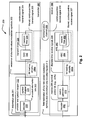
- FIG. 1 and FIG. 2 are diagrams illustrate various embodiments of communication systems, 100 and 200, respectively.
- this embodiment of a communication system 100 is a communication channel 199 that communicatively couples a communication device 110 (including a transmitter 112 having an encoder 114 and including a receiver 116 having a decoder 118) situated at one end of the communication channel 199 to another communication device 120 (including a transmitter 126 having an encoder 128 and including a receiver 122 having a decoder 124) at the other end of the communication channel 199.
- a communication device 110 including a transmitter 112 having an encoder 114 and including a receiver 116 having a decoder 118
- another communication device 120 including a transmitter 126 having an encoder 128 and including a receiver 122 having a decoder 124
- either of the communication devices 110 and 120 may only include a transmitter or a receiver.
- the communication channel 199 may be implemented (e.g., a satellite communication channel 130 using satellite dishes 132 and 134, a wireless communication channel 140 using towers 142 and 144 and/or local antennae 152 and 154, a wired communication channel 150, and/or a fiber-optic communication channel 160 using electrical to optical (E/O) interface 162 and optical to electrical (O/E) interface 164)).
- a satellite communication channel 130 using satellite dishes 132 and 134 e.g., a satellite communication channel 130 using satellite dishes 132 and 134, a wireless communication channel 140 using towers 142 and 144 and/or local antennae 152 and 154, a wired communication channel 150, and/or a fiber-optic communication channel 160 using electrical to optical (E/O) interface 162 and optical to electrical (O/E) interface 164)
- E/O electrical to optical
- O/E optical to electrical
- error correction and channel coding schemes are often employed.
- these error correction and channel coding schemes involve the use of an encoder at the transmitter and a decoder at the receiver.
- any of the various types of LDPC codes described herein can be employed within any such desired communication system (e.g., including those variations described with respect to FIG. 1 ), any information storage device (e.g., hard disk drives (HDDs), network information storage devices and/or servers, etc.) or any application in which information encoding and/or decoding is desired.
- any information storage device e.g., hard disk drives (HDDs), network information storage devices and/or servers, etc.
- any application in which information encoding and/or decoding is desired.
- information bits 201 are provided to a transmitter 297 that is operable to perform encoding of these information bits 201 using an encoder and symbol mapper 220 (which may be viewed as being distinct functional blocks 222 and 224, respectively) thereby generating a sequence of discrete-valued modulation symbols 203 that is provided to a transmit driver 230 that uses a DAC (Digital to Analog Converter) 232 to generate a continuous-time transmit signal 204 and a transmit filter 234 to generate a filtered, continuous-time transmit signal 205 that substantially comports with the communication channel 299.
- DAC Digital to Analog Converter
- continuous-time receive signal 206 is provided to an AFE (Analog Front End) 260 that includes a receive filter 262 (that generates a filtered, continuous-time receive signal 207) and an ADC (Analog to Digital Converter) 264 (that generates discrete-time receive signals 208).
- a metric generator 270 calculates metrics 209 (e.g., on either a symbol and/or bit basis) that are employed by a decoder 280 to make best estimates of the discrete-valued modulation symbols and information bits encoded therein 210.
- the transmitter 297 may include a bit loading circuitry 280a
- the receiver 298 may include a bit loading circuitry 280b.
- one or more operations within the respective communication devices may be adaptively modified.
- the various modules, circuitries, and/or functional blocks within the transmitter 297 may be adaptively directed to operate in accordance with one or more operational modes based on one or more control signals provided by the bit loading circuitry 280a.
- the various modules, circuitries, and/or functional blocks within the receiver 298 may be adaptively directed to operate in accordance with one or more operational modes based on one or more control signals provided by the bit loading circuitry 280b.
- the type of noise affecting the communication channel is frequency selective and time-varying narrowband ingress noise. Based on this type of noise, or other types of noise, various operations within the communication devices may be adaptively modified as directed by the bit loading circuitries 280a or 280b.
- Some examples of different operational modes include selecting one or more means of operation from among one or more means of operation.
- Such operational means performed in accordance with generating signals to be launched into a communication channel and/or received from a communication channel may include, but are not limited to, signaling (e.g., orthogonal frequency division multiplexing (OFDM), code division multiple access (CDMA), time division multiple access (TDMA), and/or any other type of signaling employed), modulation (e.g., constellation and symbol mapping of the constellation points therein), demodulation, metric generation, decoding (such as using a selected LDPC matrix being selected from a number of LDPC matrices), etc.
- OFDM orthogonal frequency division multiplexing
- CDMA code division multiple access
- TDMA time division multiple access
- demodulation e.g., constellation and symbol mapping of the constellation points therein
- demodulation e.g., constellation and symbol mapping of the constellation points therein
- demodulation e.g., metric generation, de
- the encoders and/or decoders of either of the previous embodiments may be implemented to include various aspects and/or embodiment of the invention therein.
- several of the following Figures describe other and particular embodiments (some in more detail) that may be used to support the devices, systems, functionality and/or methods that may be implemented in accordance with certain aspects and/or embodiments of the invention.
- One particular type of signal that is processed according to certain aspects and/or embodiments of the invention is an LDPC coded signal.
- a general description of LDPC codes is provided below as well.
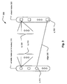
- FIG. 3 illustrates an embodiment of an LDPC (Low Density Parity Check) code bipartite graph 300.
- an LDPC bipartite graph may also sometimes be referred to as a "Tanner" graph.
- An LDPC code may be viewed as being a code having a binary parity check matrix such that nearly all of the elements of the matrix have values of zeroes (e.g., the binary parity check matrix is sparse). For example,
- LDPC codes are linear block codes and hence the set of all codewords x ⁇ C spans the null space of a parity check matrix, H .
- Hx T 0 , ⁇ x ⁇ C
- H is a sparse binary matrix of dimension m ⁇ n .
- Each row of H corresponds to a parity check and a set element h ij indicates that data symbol j participates in parity check i .
- Each column of H corresponds to a codeword symbol.
- the row and column weights are defined as the number of set elements in a given row or column of H , respectively.
- the set elements of H are chosen to satisfy the performance requirements of the code.
- the number of 1's in the i -th column of the parity check matrix , H, may be denoted as d v ( i ), and the number of 1's in the j -th row of the parity check matrix may be denoted as d c ( j ).
- the LDPC code is called a ( d v , d c ) regular LDPC code, otherwise the LDPC code is called an irregular LDPC code.
- LDPC codes were introduced by R. Gallager in [1] referenced below (also in [2] referenced below) and by M. Luby et al . in [3] also referenced below.
- a regular LDPC code can be represented as a bipartite graph 300 by its parity check matrix with left side nodes representing variable of the code bits (or alternatively as the "variable nodes" (or “bit nodes”) 310 in a bit decoding approach to decoding LDPC coded signals), and the right side nodes representing check equations (or alternatively as the "check nodes” 320).
- the bipartite graph 300 (or sometimes referred to as a Tanner graph 300) of the LDPC code defined by H may be defined by N variable nodes (e.g., N bit nodes) and M check nodes.
- Every variable node of the N variable nodes 310 has exactly d v ( i ) edges (an example edge shown using reference numeral 330) connecting the bit node, v i 312, to one or more of the check nodes (within the M check nodes).
- the edge 330 is specifically shown as connecting from the bit node, v i 312, to the check node, c j 322.
- This number of d v edges (shown as d v 314) may be referred to as the degree of a variable node i .
- every check node of the M check nodes 320 has exactly d c ( j ) edges (shown as d c 324) connecting this node to one or more of the variable nodes (or bit nodes) 310.
- This number of edges, d c may be referred to as the degree of the check node j .
- edges in the graph correspond to the set elements of H where a set element h ji indicates that an edge connects a bit (e.g., variable ) node i with parity check node j .
- an irregular LDPC code may also described using a bipartite graph.
- the degree of each set of nodes within an irregular LDPC code may be chosen according to some distribution. Therefore, for two different variable nodes, v i 1 and v i 2 , of an irregular LDPC code,
- may not equal to
- the concept of irregular LDPC codes was originally introduced within M. Luby et al . in [3] referenced above.
- the parameters of an LDPC code can be defined by a degree of distribution, as described within M. Luby et al . in [3] referenced above and also within the following reference [4]:
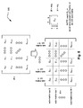
- FIG. 5 illustrates an embodiment 500 of the relationship between an overall LDPC matrix and the individual sub-matrices therein that include all zero-valued sub-matrices and/or CSI (Cyclic Shifted Identity) sub-matrices (including the sub-matrix rows and sub-matrix columns of the LDPC matrix).
- a binary LDPC code may be fully described by its parity check matrix (i.e., its LDPC matrix).
- H h 0 , 0 h 0 , 1 ⁇ h 0 , n - 1 h 1 , 0 h 1 , 1 ⁇ h 1 , n - 1 ⁇ ⁇ ⁇ ⁇ h m - 1 , 0 h m - 1 , 1 ⁇ h m - 1 , n - 1 where n is the number of bits in a codeword, m is the number of parity check equations of the LDPC code, and h i,j is either 0 or 1.
- n -bit vector c ( c 1 , c 2 , ... , c N )
- c ( c 1 , c 2 , ... , c N )
- the LDPC matrix (as depicted in the lower portion of the diagram), includes various sub-matrix rows and sub-matrix columns. These sub-matrix rows and sub-matrix columns may be viewed as being based on the sub-matrix construction of the LDPC matrix (e.g., shown as sub-matrix rows 0 through M -1 and sub-matrix columns 0 through N -1).
- Certain communication systems and the communication devices therein may suffer undesirably from narrowband ingress noise. While many of the illustrative embodiments depicted herein relate to home networking type of communication systems (e.g., multiple communication devices being networked together in a relatively small vicinity such as in accordance with MoCA 2.0 (Multimedia over Coax Alliance 2.0)), the deleterious effects of narrowband ingress noise are certainly not limited only to such types of communication systems and such communication devices implemented therein, and such undesirable narrowband ingress noise may be found in other types of communication systems and among other types of communication devices as well without departing from the scope and spirit of the invention.
- home networking type of communication systems e.g., multiple communication devices being networked together in a relatively small vicinity such as in accordance with MoCA 2.0 (Multimedia over Coax Alliance 2.0)
- MoCA 2.0 Multimedia over Coax Alliance 2.0
- Ingress noise may be defined as a frequency selective impairment in contrast with impulse noise.
- Narrowband ingress noise may be injected into a communication network itself (e.g., a home networking type of communication system). The amplitude of the injected ingress may vary as a function of the propagation condition within the communication system, and such variation may be by as much as 20 dB.
- MoCA 2.0 Multimedia over Coax Alliance 2.0
- MoCA 2.0 includes a number of baseline orthogonal frequency division multiplexing (OFDM) operational parameters including:
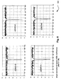
- FIG. 6 illustrates an embodiment 600 of signal to noise ratio (SNR) with a single interferer causing ingress noise in an orthogonal frequency division multiplexing (OFDM) operative communication system.
- SNR signal to noise ratio
- OFDM orthogonal frequency division multiplexing
- FIG. 7 illustrates an embodiment 700 of SNR with three interferers causing ingress noise in OFDM.
- the first interferer incurs a loss of SNR centered on a sub-carrier just greater than 100 of the available 480 sub-carriers.
- the second interferer incurs a loss of SNR centered on a sub-carrier between 250 and 300 of the available 480 sub-carriers.
- the third interferer incurs a loss of SNR centered on a sub-carrier between 400 and 450 of the available 480 sub-carriers.
- FIG. 8 illustrates various embodiments 800 of ⁇ SNR (i.e., various changes in SNR) with a single interferer causing ingress noise in OFDM. Again in this example, it can be seen that the single interferer incurs a loss of SNR centered on a sub-carrier between 250 and 300 of the available 480 sub-carriers.
- the depth of the notch caused by the narrowband ingress noise is approximately similar regardless of the change in SNR.
- This diagram shows different SNR for the available 480 sub-carriers:
- the simulation is performed on QAM of sizes 32/64.
- the dBc of the ingress is fixed/static, and the ⁇ SNR does change.
- FIG. 9 illustrates an embodiment 900 of a performance comparison between an 80% LDPC code and a 90% LDPC code.
- code rate or percentage may be interpreted to be at the said code rate or percentage within some predetermined tolerance such as 0.1%, 0.3%, 1%, 3%, and/or other tolerance etc.).
- the 90% LDPC code has better performance, and both of the codes have an error floor of approximately 1 ⁇ 10 -4 .
- the performance of such rate 90% codes is generally not very good, and this may be attributed to various parameters including: the relatively high code rate of the codes, the sub-matrix size is too small, and/or that the LDPC code is not a regular LDPC code (i.e., it is irregular).
- FIG. 10 illustrates an embodiment 1000 of a performance comparison between various LDPC codes whose corresponding LDPC matrices have relatively larger sub-matrix sizes or effective factor (EF). This diagram shows various 90% LDPC codes with different sub-matrix sizes.
- a first LDPC code (irregular in nature) has block size of 4640, with code rate 89.7%, and has a sub-matrix size of 80 ⁇ 80.
- a second LDPC code (regular in nature) has block size of 5800, with code rate 89.7%, and has a sub-matrix size of 100 ⁇ 100.
- a third LDPC code (regular in nature) has block size of 10440, with code rate 89.7%, and has a sub-matrix size of 180 ⁇ 180.
- a fourth LDPC code (regular in nature) has block size of 14848, with code rate 89.7%, and has a sub-matrix size of 256 ⁇ 256.
- Some MoCA 2.0 applications require very high throughout that can approach up to 500 Mbps with 100 MHz bandwidth and 1000 Mbps with 200 MHz bandwidth. To achieve these relatively high rates with the required margin, the high code rate of 90% is required.
- the actual applied code is configured either statically by configuration SW or set dynamically by inspecting the level of the non-stationary narrowband ingress noise and by deciding which code to apply according to level of the NBI noise.
- the base matrix is expanded by replacing each 1 in the base matrix with a z ⁇ z permutation matrix, and each 0 with a z ⁇ z zero matrix (i.e., all elements therein are 0, an all zero-valued sub-matrix). This value of z may be referred to as the sub-matrix size.
- the permutations used are circular right shifts, and the set of permutation matrices contains the z ⁇ z identity matrix and circular right shifted versions of the identity matrix.
- each permutation matrix is specified by a single circular right shift
- the binary base matrix information and permutation replacement information can be combined into a single compact model matrix H bm .
- the model matrix H bm is the same size as the binary base matrix H b , with each binary entry ( i , j ) of the base matrix Hb replaced to create the model matrix H bm .
- H b Each 0 in H b is replaced by a blank or "-" negative to denote a z ⁇ z zero matrix (i.e., all elements therein are 0, an all zero-valued sub-matrix), and each 1 in H b size p ( i,j ) ⁇ 0.
- the model matrix H bm can then be directly expanded to H.
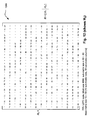
- Each sub-matrix within the LDPC matrix not depicted by a "-" is a CSI sub-matrix is characterized by a shift-value, ⁇ ( S ).
- ⁇ ( S ) the sub-matrix located in the 3 rd from the top sub-matrix row and the left hand most sub-matrix column has a value of 13, and is therefore a CSI sub-matrix with a shift-value of 13, ⁇ (13).
- all of the sub-matrices depicted as a "-" are all zero-valued sub-matrices.
- the block size of this LDPC code is 4640, and the sub-matrices are all size 80 by 80 (i.e., 80 rows and 80 columns each).
- the information bit component of this LDPC matrix shown as the left hand side matrix ( H 1 ), being composed of both H 1a and H 1b , is regular (as described above, and particularly in regards to this portion of the LDPC matrix having the same bit degree). Ensuring that the left hand side matrix ( H 1 ) is regular, the corresponding LDPC matrix has robustness to ingress noise (such as NBI that may be encountered within home networking type communication systems) and can provide for lower error rates thereby providing greater information throughput and better performance.
- the right hand side matrix ( H 2 ) which is shown as being lower diagonal in nature in this embodiment, may be irregular.
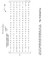
- Each sub-matrix within the LDPC matrix not depicted by a "-" is a CSI sub-matrix is characterized by a shift-value, ⁇ ( S ).
- the sub-matrix located in the top sub-matrix row and the left hand most sub-matrix column has a value of 72, and is therefore a CSI sub-matrix with a shift-value of 72, ⁇ (72).
- all of the sub-matrices depicted as a "-" are all zero-valued sub-matrices (i.e., all of the entries within such sub-matrices are zero in value, 0).
- the block size of this LDPC code is 4600, and the sub-matrices are all size 100 by 100 (i.e., 100 rows and 100 columns each).
- such an LDPC matrix is composed of sub-matrices each having a common size (e.g., 100 by 100 in this instance), and the LDPC matrix is partitioned into a left hand side matrix and a right hand side matrix.
- the left hand side matrix ( H 1 ) is composed of both H 1a and H 1b
- the right hand side matrix being ( H 2 ).
- Each sub-matrix within the right hand side matrix, H 2 is an all zero-valued sub-matrix except those sub-matrices identified in (a) and (b): (a) each sub-matrix located on a diagonal of the right hand side matrix being a respective CSI (Cyclic Shifted Identity) sub-matrix, the diagonal extending from an upper left most sub-matrix of the right hand side matrix to a lower right hand sub-matrix of the of the right hand side matrix, and (b) each sub-matrix being located below the diagonal of the right hand side matrix also being a respective CSI sub-matrix.
- the right hand side matrix may be viewed as being a lower diagonal matrix such that all of the sub-matrices located in the upper right hand portion of the right hand side matrix are all zero-valued sub-matrices.
- each respective CSI sub-matrix may have a different and respective CSI value.
- the CSI value of a given CSI sub-matrix is zero (0), making that CSI sub-matrix being an identity sub-matrix or a CSI sub-matrix having undergone a cyclic shift of zero (i.e., having not undergone any cyclic shifting).
- each sub-matrix within the left hand side matrix may be a respective CSI sub-matrix (e.g., the left hand side matrix not including any all zero-valued sub-matrices therein), but rather only respective CSI sub-matrices.
- other embodiments may include a left hand side matrix that includes one or more all zero-valued sub-matrix therein).
- such an LDPC as constructed in accordance with the embodiment 1300/1400 may be a regular LDPC code.
- irregular LDPC matrices may alternatively be constructed and employed without departing from the scope and spirit of various aspects of the invention.
- Each sub-matrix within the LDPC matrix not depicted by a "-" is a CSI sub-matrix is characterized by a shift-value, ⁇ ( S ).
- ⁇ ( S ) the sub-matrix located in the top sub-matrix row and the left hand most sub-matrix column has a value of 0, and is therefore a CSI sub-matrix with a shift-value of 0, ⁇ (0) [which is an Identity sub-matrix].
- all of the sub-matrices depicted as a "-" are all zero-valued sub-matrices.
- the block size of this LDPC code is 4608, and the sub-matrices are all size 96 by 96 (i.e., 96 rows and 96 columns each).
- FIG. 17 illustrates an embodiment 1700 of a distribution of constellation sizes among various sub-carriers within an OFDM operative communication system. This diagram corresponds to a rate 90% LDPC code.
- This embodiment 1700 shows a relatively close distribution between the 5 bits symbols (32 QAM) and 6 bit symbols (64 QAM) (e.g., 275 to 197).
- a communication device may adaptively select a first such distribution from among a plurality of distributions.
- a communication device may adaptively switch from a first distribution to a second distribution.
- One such example of such a change may correspond to frequency selective and time-varying narrowband ingress noise that may undesirably and deleteriously affect a communication channel via which a communication device communicates with at least one additional communication device.
- FIG. 18 , FIG. 19 , and FIG. 20 illustrate various embodiments 1800, 1900, and 2000 of distribution of constellation sizes among various sub-carriers within OFDM operative communication systems.
- this diagram corresponds to a rate 85% LDPC code. Also in this diagram, two different types of modulation symbols are employed: those having 5 bits which are mapped to a 32 QAM constellation, and those having 6 bits which are mapped to a 64 QAM constellation.
- This embodiment 1800 shows a broader distribution between the 5 bits symbols (32 QAM) and 6 bit symbols (64 QAM) (e.g., 179 to 293).
- this diagram corresponds to a rate 80% LDPC code.
- two different types of modulation symbols are employed: those having 6 bits which are mapped to a 64 QAM constellation, and those having 7 bits which are mapped to a 128 QAM constellation.
- This embodiment 1900 shows a very broad distribution between the 6 bit symbols (64 QAM) and 7 bits symbols (128 QAM) and (e.g., 409 to 63).
- this diagram corresponds to a rate 75% LDPC code. Also in this diagram, two different types of modulation symbols are employed: those having 6 bits which are mapped to a 64 QAM constellation, and those having 7 bits which are mapped to a 128 QAM constellation.
- This embodiment 2000 shows a relatively close distribution between the 6 bit symbols (64 QAM) and 7 bits symbols (128 QAM) and (e.g., 237 to 235).
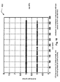
- FIG. 21 illustrates an embodiment 2100 of a performance comparison between various LDPC codes within an OFDM operative communication system operating at 400 Mega-bits per second (Mb/s or Mbps).
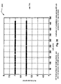
- FIG. 22 illustrates an embodiment 2200 of a performance comparison between various LDPC codes within an OFDM operative communication system operating at 600 Mb/s.
- the 79% LDPC code of FIG. 15 and FIG. 16 is less robust than the 74% LDPC code of FIG. 11 and FIG. 12 by approximately 5.5 dBc or 4.5 dBc. Also, the 79% LDPC code of FIG. 15 and FIG. 16 is only approximately 1 dBc more robust than the 84.8% LDPC code of FIG. 13 and FIG. 14 .
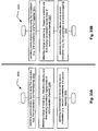
- FIG. 23A illustrates an embodiment of a method 2300 for employing LDPC coding to generate a coded signal that is robust to narrowband ingress noise.
- the method 2300 begins by receiving information bits, as shown in a block 2310.
- the method 2300 continues by encoding information bits using generator matrix corresponding to LDPC matrix (which is tailored for narrowband ingress noise immunity) thereby generating LDPC code block, as shown in a block 2320.
- the generator matrix is merely the LDPC matrix itself.
- the corresponding LDPC code is a systematic code, and LDPC encoding can be employed using this LDPC matrix itself by simply performing back substitution.
- the method 2300 then operates by symbol mapping selected bits of LDPC code block using at least one modulation (i.e., at least one constellation with at least one corresponding mapping of constellation points therein) thereby generating modulation symbols, as shown in a block 2330.
- at least one modulation i.e., at least one constellation with at least one corresponding mapping of constellation points therein
- the method 2300 continues by converting modulation symbols into continuous-time signal, as shown in a block 2340.
- the method 2300 then operates by launching continuous-time signal into communication channel, as shown in a block 2350.
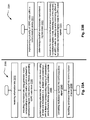
- FIG. 23B illustrates an embodiment of a method 2301 for selectively employing one type of LDPC coding to reduce and/or minimize the effect of narrowband ingress noise in LDPC coded signals.
- the method 2301 begins by implementing a plurality of LDPC codes within a communication device, as shown in a block 2311.
- the method 2301 then operates by determining a level of non-stationary narrowband ingress noise, as shown in a block 2321.
- the method 2301 continues by based on the determined level of level of non-stationary narrowband ingress noise, selecting one of the plurality of LDPC codes for reducing and/or minimizing effect of non-stationary narrowband ingress noise in LDPC coded signals, as shown in a block 2331.
- Each sub-matrix within the LDPC matrix not depicted by a "-" is a CSI sub-matrix is characterized by a shift-value, ⁇ ( S ).
- ⁇ ( S ) the sub-matrix located in the top sub-matrix row and the left hand most sub-matrix column has a value of 6, and is therefore a CSI sub-matrix with a shift-value of 6, ⁇ (6).
- all of the sub-matrices depicted as a "-" are all zero-valued sub-matrices.
- the block size of this regular LDPC code is 4640, and the sub-matrices are all size 80 by 80 (i.e., 80 rows and 80 columns each).
- modulation e.g., constellations with respective mapping of the constellation points therein
- types of modulation e.g., constellations with respective mapping of the constellation points therein
- a modulation that includes more constellation points therein can carry more information and is less robust (e.g., more susceptible to noise, interference, etc.) than another modulation that includes fewer constellation points therein can carry less information and is more robust (e.g., less susceptible to noise, interference, etc.).
- a communication device may adaptively modify any one or more of its operational parameters (e.g., may be viewed as adaptively selecting between various operational modes).
- a first operational mode may include a first set of operational parameters by which a communication device operates
- a second operational mode may include a second set of operational parameters by which the communication device operates.
- the adaptive modification between operational modes may involve switching between as few as one operational parameter to another.
- FIG. 26 illustrates embodiments of a binary phase shift keying (BPSK) modulation, shown by reference numeral 2600, and a quadrature phase shift keying (QPSK) modulation (or a 4 quadrature amplitude modulation (4 QAM)), shown by reference numeral 2601.
- BPSK binary phase shift keying
- QPSK quadrature phase shift keying
- 4 QAM 4 quadrature amplitude modulation
- a BPSK modulation includes only 2 constellation points there, and a singular bit is mapped to one of the constellation points. In such a BPSK constellation, the single bit may be viewed as being a pone bit symbol.
- a QPSK modulation includes 4 constellation points therein, and 2 bit symbol is mapped to one of the constellation points.
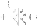
- FIG. 27 illustrates embodiments of 8 QAM, shown by reference numeral 2700.
- the 8 QAM is one variant of a 2 2n+1 QAM type modulation.
- a description of a 2 2n+1 QAM type modulation is provided below.
- a 2 2n+1 QAM type modulation operates on symbols having 2n+1 bits, such that the various bits of the symbol are depicted as ( a 2n , a 2n-1 , a 2n-2 , ..., a 1 , a 0 ) ⁇ ( I, Q ) and are mapped in accordance with in-phase and quadrature axes of the particular modulation's constellation.
- Such a 2 2n+1 QAM type modulation is not necessarily a square constellation in accordance with other QAM type modulations, and such a 2 2n+1 QAM type modulation itself includes 2 2n+1 constellation points.
- the first two most significant bits (MSBs) namely, a 2n , a 2n-1 , determine the quadrant, as defined by the ( I , Q ) axes, in which the remainder of the bits are symbol mapped.
- a 2n , a 2n-1 are (0,0) ⁇ (+,+) [which is the upper right hand quadrant].
- a 2n , a 2n-1 are (0,1) ⁇ (-,+) [which is the upper left hand quadrant].
- the first two MSBs, a 2n , a 2n-1 are (1,1) ⁇ (-,-) [which is the lower left hand quadrant].
- the first two MSBs, a 2n , a 2n-1 are, (1,0) ⁇ (+,-) [which is the lower right hand quadrant].
- the constellation points therein may be viewed as being a subset of the constellation points within a 16 QAM (e.g., see FIG. 28 for one such example). It is of course noted that a different subset of such a 16 QAM may alternatively be selected to form a 8 QAM in other embodiments.
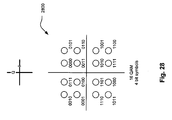
- FIG. 28 illustrates an embodiment of 16 QAM, shown by reference numeral 2800.
- FIG. 29 illustrates an embodiment of 32 QAM, shown by reference numeral 2900.
- first two MSBs, a 4 , a 3 , of the 5 bit symbols are those that select which one of the four quadrants in which the remaining 3 bits, a 2 , a 1 , a 0 , are to be symbol mapped.
- Each of the four quadrants consequently includes 8 respective constellation points therein.
- FIG. 30 illustrates an embodiment of 128 QAM, shown by reference numeral 3000.
- first two MSBs, a 6 , a 5 , of the 7 bit symbols are those that select which one of the four quadrants in which the remaining 5 bits, a 4 , a 3 , a 2 , a 1 , a 0 , are to be symbol mapped.
- Each of the four quadrants consequently includes 32 respective constellation points therein.
- FIG. 31 illustrates an embodiment of 512 QAM, shown by reference numeral 3100.
- first two MSBs, a 8 , a 7 , of the 9 bit symbols are those that select which one of the four quadrants in which the remaining 7 bits, a 6 , a 5 , a 4 , a 3 , a 2 , a 1 , a 0 , are to be symbol mapped.
- Each of the four quadrants consequently includes 128 respective constellation points therein.
- the symbol mapping of the constellation points within a given modulation may be adaptively or dynamically modified. For example, the constellation points within a modulation having may be symbol mapped in accordance with a first symbol mapping at a first time, and the constellation points within a similarly shaped modulation may be symbol mapped in accordance with second symbol mapping at a second time.
- the adaptive modification may be made from a first modulation to a second modulation entirely, or alternatively, from a first symbol mapping of a modulation to a second symbol mapping of that very same modulation (i.e., the same shaped constellation with at least two different mappings thereof), may be performed in response to or based on a change of one or more operational conditions of a communication system and/or communication device, a communication device may adaptively switch from a first distribution to a second distribution.
- a change may correspond to frequency selective and time-varying narrowband ingress noise that may undesirably and deleteriously affect a communication channel via which a communication device communicates with at least one additional communication device.
- FIG. 32A illustrates an embodiment of a method 3200 for operating a communication device.
- the method 3200 begins by operating communication device in accordance with first operational mode, as shown in a block 3210.
- the method 3200 continues by monitoring one or more operational parameters including any change thereof (e.g., communication channel noise of various types, communication device status, BER, SNR, etc.), as shown in a block 3220.
- the method 3200 Based on monitored one or more operational parameters or change thereof, the method 3200 then operates by operating communication device in accordance with second operational mode, as shown in a block 3230.
- a communication device may adaptively modify any one or more of its operational parameters (e.g., may be viewed as adaptively selecting between various operational modes).
- a first operational mode may include a first set of operational parameters by which a communication device operates
- a second operational mode may include a second set of operational parameters by which the communication device operates.
- the adaptive modification between operational modes may involve switching between as few as one operational parameter to another; in other words, two different operational modes may include nearly the entirely the same operational parameters save one operational parameter.
- multiple operational parameters may be modified when switching from one operational mode to another.
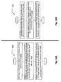
- FIG. 32B illustrates an alternative embodiment of a method 3201 for operating a communication device.
- the method 3201 begins by operating communication device using first symbol distribution in accordance with OFDM signaling, as shown in a block 3211.
- the method 3201 then operates by detecting change of noise (e.g., frequency selective and time-varying narrowband ingress noise of communication channel), as shown in a block 3221.
- the method 3201 continues by operating communication device using second symbol distribution in accordance with OFDM signaling, as shown in a block 3231.
- change of noise e.g., frequency selective and time-varying narrowband ingress noise of communication channel
- various embodiments herein relate to distributions between symbols of different sizes that are distributed between various sub-carriers in accordance with OFDM signaling.
- a communication device may be operated to switch from a first symbol distribution to a second symbol distribution.
- FIG. 33A and FIG. 33B illustrate various alternative embodiments of methods 3300 and 3301 for operating a communication device.
- the method 3300 begins by operating communication device using first modulation (e.g., first constellation and first mapping), as shown in a block 3310.
- the method 3300 continues by detecting change of noise (e.g., frequency selective and time-varying narrowband ingress noise of communication channel), as shown in a block 3320.
- the method 3300 then operates by operating communication device using second modulation (e.g., second constellation and second mapping), as shown in a block 3330.
- first modulation e.g., first constellation and first mapping
- change of noise e.g., frequency selective and time-varying narrowband ingress noise of communication channel
- second modulation e.g., second constellation and second mapping
- a communication device may be operated to switch from a first modulation to a second modulation.
- a communication device may be operated to switch from a first modulation that has a larger number of constellation points therein to a second modulation that has a fewer number of constellation points therein.
- the communication device may be operated to switch to a more robust modulation (that may provide for less overall throughput but will still operate in accordance with an acceptable error rate).
- a communication device when there is a decrease in noise, a communication device may be operated to switch from a first modulation that has a fewer number of constellation points therein to a second modulation that has a larger number of constellation points therein. For example, as the noise decreases, the communication device may be operated to switch to a less robust modulation that may provide for a greater throughput.
- the method 3301 begins by operating communication device using first modulation (e.g., first constellation and first mapping), as shown in a block 3311.
- the method 3301 then operates by detecting change of noise (e.g., frequency selective and time-varying narrowband ingress noise of communication channel), as shown in a block 3321.
- the method 3301 continues by operating communication device using second modulation (e.g., first constellation and second mapping), as shown in a block 3331.
- the first and second modulations have the same constellation but each has a different respective symbol mapping therein.
- modules and/or circuitries may be a single processing device or a plurality of processing devices.
- a processing device may be a microprocessor, micro-controller, digital signal processor, microcomputer, central processing unit, field programmable gate array, programmable logic device, state machine, logic circuitry, analog circuitry, digital circuitry, and/or any device that manipulates signals (analog and/or digital) based on operational instructions.
- the operational instructions may be stored in a memory.
- the memory may be a single memory device or a plurality of memory devices.
- Such a memory device may be a read-only memory (ROM), random access memory (RAM), volatile memory, non-volatile memory, static memory, dynamic memory, flash memory, and/or any device that stores digital information.
- ROM read-only memory
- RAM random access memory
- volatile memory non-volatile memory
- static memory dynamic memory
- flash memory flash memory
- any device that stores digital information any device that stores digital information.
- the processing module implements one or more of its functions via a state machine, analog circuitry, digital circuitry, and/or logic circuitry
- the memory storing the corresponding operational instructions is embedded with the circuitry comprising the state machine, analog circuitry, digital circuitry, and/or logic circuitry.
- a memory stores, and a processing module coupled thereto executes, operational instructions corresponding to at least some of the steps and/or functions illustrated and/or described herein.
- connections or couplings between the various modules, circuits, functional blocks, components, devices, etc. within any of the various diagrams or as described herein may be differently implemented in different embodiments.
- such connections or couplings may be direct connections or direct couplings there between.
- such connections or couplings may be indirect connections or indirect couplings there between (e.g., with one or more intervening components there between).
- certain other embodiments may have some combinations of such connections or couplings therein such that some of the connections or couplings are direct, while others are indirect.
- Different implementations may be employed for effectuating communicative coupling between modules, circuits, functional blocks, components, devices, etc. without departing from the scope and spirit of the invention.
Landscapes
- Physics & Mathematics (AREA)
- Mathematical Physics (AREA)
- Probability & Statistics with Applications (AREA)
- Engineering & Computer Science (AREA)
- Theoretical Computer Science (AREA)
- Error Detection And Correction (AREA)
Abstract
Description
- The present U.S. Utility Patent Application claims priority pursuant to 35 U.S.C. § 119(e) to the following U.S. Provisional Patent Applications which are hereby incorporated herein by reference in their entirety and made part of the present U.S. Utility Patent Application for all purposes:
- 1.
U.S. Provisional Application Serial No. 61/164,814 - 2.
U.S. Provisional Application Serial No. 61/167,354 - The invention relates generally to communication systems that incur and suffer deleteriously from ingress noise; and, more particularly, it relates to communication devices implemented within such communication systems that are robust to such ingress noise.
- Data communication systems have been under continual development for many years. One such type of communication system that has been of significant interest lately is a communication system that employs iterative error correction codes (ECCs). Of particular interest is a communication system that employs LDPC (Low Density Parity Check) code. Communications systems with iterative codes are often able to achieve lower bit error rates (BER) than alternative codes for a given signal to noise ratio (SNR).
- A continual and primary directive in this area of development has been to try continually to lower the SNR required to achieve a given BER within a communication system. The ideal goal has been to try to reach Shannon's limit in a communication channel. Shannon's limit may be viewed as being the data rate to be used in a communication channel, having a particular SNR, that achieves error free transmission through the communication channel. In other words, the Shannon limit is the theoretical bound for channel capacity for a given modulation and code rate.
- LDPC code has been shown to provide for excellent decoding performance that can approach the Shannon limit in some cases. For example, some LDPC decoders have been shown to come within 0.3 dB (decibels) from the theoretical Shannon limit. While this example was achieved using an irregular LDPC code with a length of one million, it nevertheless demonstrates the very promising application of LDPC codes within communication systems.
- The use of LDPC coded signals continues to be explored within many newer application areas. Some examples of possible communication systems that may employ LDPC coded signals include communication systems employing 4 wire twisted pair cables for high speed Ethernet applications (e.g., 10Gbps (Giga-bits per second) Ethernet operation according to the IEEE 802.3an (IOGBASE-T) emerging standard) as well as communication systems operating within a wireless context (e.g., in the IEEE 802.11 context space including the IEEE 802.11 n emerging standard).
- For any of these particular communication system application areas, near-capacity achieving error correction codes are very desirable. The latency constraints, which would be involved by using traditional concatenated codes, simply preclude their use in such applications in very high data rate communication system application areas.
- Generally speaking, within the context of communication systems that employ LDPC codes, there is a first communication device at one end of a communication channel with encoder capability and second communication device at the other end of the communication channel with decoder capability. In many instances, one or both of these two communication devices includes encoder and decoder capability (e.g., within a bi-directional communication system). LDPC codes can be applied in a variety of additional applications as well, including those that employ some form of data storage (e.g., hard disk drive (HDD) applications and other memory storage devices) in which data is encoded before writing to the storage media, and then the data is decoded after being read/retrieved from the storage media.
- The present invention is directed to apparatus and methods of operation that are further described in the following Brief Description of the Several Views of the Drawings, the Detailed Description of the Invention, and the claims. Other features and advantages of the present invention will become apparent from the following detailed description of the invention made with reference to the accompanying drawings.
- According to an aspect, an apparatus comprises:
- an input for receiving an LDPC (Low Density Parity Check) coded signal; and
- an LDPC decoder for employing an LDPC matrix for decoding the LDPC coded signal to make an estimate of an information bit encoded therein; and wherein:
- the LDPC matrix, composed of a plurality of sub-matrices each having a common size, being partitioned into a left hand side matrix and a right hand side matrix; and
- each sub-matrix within the right hand side matrix being an all zero-valued sub-matrix except those sub-matrices identified in (a) and (b):
- (a) each sub-matrix located on a diagonal of the right hand side matrix being a respective CSI (Cyclic Shifted Identity) sub-matrix, the diagonal extending from an upper left most sub-matrix of the right hand side matrix to a lower right hand sub-matrix of the of the right hand side matrix; and
- (b) each sub-matrix being located below the diagonal of the right hand side matrix also being a respective CSI sub-matrix.
- Advantageously:
- each sub-matrix within the left hand side matrix being a respective CSI sub-matrix.
- Advantageously:
- at least one of the sub-matrices in the left hand side matrix being an identity sub-matrix or a CSI sub-matrix having undergone a cyclic shift of zero.
- Advantageously, the apparatus further comprises:
- an analog front end (AFE); and wherein:
- the LDPC coded signal being received from a communication channel being affected from frequency selective and time-varying narrowband ingress noise;
- during a first time, the input receiving the LDPC coded signal including a first plurality of symbols each having a first number of bits and a second plurality of symbols each having a second number of bits such that first plurality of symbols and the second plurality of symbols being distributed among a plurality of sub-carriers in accordance with orthogonal frequency division multiplexing (OFDM) signaling in accordance with a first distribution; and
- based on a change of the frequency selective and time-varying narrowband ingress noise affecting the communication channel, during a second time, the input receiving the LDPC coded signal including a third plurality of symbols each having the first number of bits and a fourth plurality of symbols each having the second number of bits such that third plurality of symbols and the fourth plurality of symbols being distributed among a plurality of sub-carriers in accordance with OFDM signaling in accordance with a second distribution;
- the AFE extracting the first plurality of symbols and the second plurality of symbols from the LDPC coded signal based on the first distribution; and
- the AFE extracting the third plurality of symbols and the fourth plurality of symbols from at least one additional LDPC coded signal based on the second distribution.
- Advantageously, the apparatus further comprises:
- a metric generator; and wherein:
- the LDPC coded signal being received from a communication channel being affected from frequency selective and time-varying narrowband ingress noise;
- during a first time, the input receiving the LDPC coded signal including a first plurality of symbols therein being mapped using a first constellation having a first number of constellation points therein;
- based on a change of the frequency selective and time-varying narrowband ingress noise affecting the communication channel, during a second time, the input receiving at least one additional LDPC coded signal including a second plurality of symbols therein being mapped using a second constellation having a second number of constellation points therein;
- the metric generator calculating a first plurality of metrics corresponding to the first plurality of symbols based on the first constellation; and
- the metric generator calculating a second plurality of metrics corresponding to the second plurality of symbols based on the second constellation.
- Advantageously:
- the change of the frequency selective and time-varying narrowband ingress noise affecting the communication channel being an increase in the frequency selective and time-varying narrowband ingress noise; and
- the first number of constellation points being greater in number than the second number of constellation points.
- Advantageously:
- the LDPC coded signal being generated in accordance with a regular LDPC code.
- Advantageously, the apparatus further comprises:
- a bit loading circuitry; and wherein:
- the LDPC coded signal being received from a communication channel being affected from frequency selective and time-varying narrowband ingress noise;
- during a first time, the input receiving the LDPC coded signal being generated using an LDPC code;
- based on a change of the frequency selective and time-varying narrowband ingress noise affecting the communication channel, during a second time, the input receiving the at least one additional LDPC coded signal being generated using at least one additional LDPC code;
- the bit loading circuitry directing the LDPC decoder to employ the LDPC matrix for decoding the LDPC coded signal to make an estimate of an information bit encoded therein; and
- based on the change of the frequency selective and time-varying narrowband ingress noise affecting the communication channel, the bit loading circuitry adaptively directing the LDPC decoder to employ at least one additional LDPC matrix for decoding the at least one additional LDPC coded signal to make an estimate of an information bit encoded therein.
- Advantageously:
- an information block size of the LDPC coded signal is 4600 bits;
- the LDPC coded signal having a code rate of 84.8%;
- each of the plurality of sub-matrices is a 100 × 100 square sub-matrix respectively having 100 rows and 100 columns; and
- the LDPC matrix includes 7 sub-matrix rows and 46 sub-matrix columns.
- Advantageously:
- the apparatus being a communication device; and
- the communication device being operative within at least one of a satellite communication system, a wireless communication system, a wired communication system, and a fiber-optic communication system.
- According to an aspect, an apparatus comprises:
- an input for receiving an LDPC (Low Density Parity Check) coded signal from a communication channel being affected from frequency selective and time-varying narrowband ingress noise;
- an analog front end (AFE) for extracting a plurality of symbols from the LDPC coded signal, the plurality of symbols being modulated within the LDPC coded signal in accordance with orthogonal frequency division multiplexing (OFDM) signaling;
- an LDPC decoder for employing an LDPC matrix for decoding the plurality of symbols of the LDPC coded signal to make estimates of information bits encoded therein; and
- a bit loading circuitry for adaptively directing operations of the AFE and the LDPC decoder based on the frequency selective and time-varying narrowband ingress noise; and wherein:
- the LDPC matrix, composed of a plurality of sub-matrices each having a common size, being partitioned into a left hand side matrix and a right hand side matrix;
- each sub-matrix within the right hand side matrix being an all zero-valued sub-matrix except those sub-matrices identified in (a) and (b):
- (a) each sub-matrix located on a diagonal of the right hand side matrix being a respective CSI sub-matrix, the diagonal extending from an upper left most sub-matrix of the right hand side matrix to a lower right hand sub-matrix of the of the right hand side matrix; and
- (b) each sub-matrix being located below the diagonal of the right hand side matrix also being a respective CSI sub-matrix.
- Advantageously:
- each sub-matrix within the left hand side matrix being a respective CSI (Cyclic Shifted Identity) sub-matrix; and
- at least one of the sub-matrices in the left hand side matrix being a CSI sub-matrix having undergone a cyclic shift of zero.
- Advantageously, the apparatus further comprises:
- a metric generator; and wherein:
- during a first time, the input receiving the LDPC coded signal including the plurality of symbols therein being mapped using a constellation having a number of constellation points therein;
- based on a change of the frequency selective and time-varying narrowband ingress noise affecting the communication channel, during a second time, the input receiving at least one additional LDPC coded signal including at least one additional plurality of symbols therein being mapped using at least one additional constellation having at least one additional number of constellation points therein;
- the metric generator calculating a plurality of metrics corresponding to the plurality of symbols based on the constellation; and
- the metric generator calculating at least one additional plurality of metrics corresponding to the at least one additional plurality of symbols based on the at least one additional constellation.
- Advantageously:
- an information block size of the LDPC coded signal is 4600 bits;
- the LDPC coded signal having a code rate of 84.8%;
- each of the plurality of sub-matrices is a 100 × 100 square sub-matrix respectively having 100 rows and 100 columns; and
- the LDPC matrix includes 7 sub-matrix rows and 46 sub-matrix columns.
- Advantageously:
- the apparatus being a communication device; and
- the communication device being operative within at least one of a satellite communication system, a wireless communication system, a wired communication system, and a fiber-optic communication system.
- According to an aspect, a method for operating a communication device comprises:
- receiving an LDPC (Low Density Parity Check) coded signal; and
- operating an LDPC decoder, within the communication device, for employing an LDPC matrix for decoding the LDPC coded signal to make an estimate of an information bit encoded therein; and wherein:
- the LDPC matrix, composed of a plurality of sub-matrices each having a common size, being partitioned into a left hand side matrix and a right hand side matrix; and
- each sub-matrix within the right hand side matrix being an all zero-valued sub-matrix except those sub-matrices identified in (a) and (b):
- (a) each sub-matrix located on a diagonal of the right hand side matrix being a respective CSI (Cyclic Shifted Identity) sub-matrix, the diagonal extending from an upper left most sub-matrix of the right hand side matrix to a lower right hand sub-matrix of the of the right hand side matrix; and
- (b) each sub-matrix being located below the diagonal of the right hand side matrix also being a respective CSI sub-matrix.
- Advantageously:
- each sub-matrix within the left hand side matrix being a respective CSI (Cyclic Shifted Identity) sub-matrix; and
- at least one of the sub-matrices in the left hand side matrix being a CSI sub-matrix having undergone a cyclic shift of zero.
- Advantageously, the method further comprises:
- receiving the LDPC coded signal from a communication channel being affected from frequency selective and time-varying narrowband ingress noise;
- based on the frequency selective and time-varying narrowband ingress noise, adaptively directing operation of the LDPC decoder, the LDPC decoder being operative within a plurality of operational modes.
- Advantageously:
- an information block size of the LDPC coded signal is 4600 bits;
- the LDPC coded signal having a code rate of 84.8%;
- each of the plurality of sub-matrices is a 100 × 100 square sub-matrix respectively having 100 rows and 100 columns; and
- the LDPC matrix includes 7 sub-matrix rows and 46 sub-matrix columns.
- Advantageously:
- the method being performed within a communication device; and
- the communication device being operative within at least one of a satellite communication system, a wireless communication system, a wired communication system, and a fiber-optic communication system.
-
-
FIG. 1 andFIG. 2 illustrate various embodiments of communication systems. -
FIG. 3 illustrates an embodiment of an LDPC (Low Density Parity Check) code bipartite graph. -
FIG. 4A illustrates an embodiment of variable node update with reference to an LDPC code bipartite graph. -
FIG. 4B illustrates an embodiment of check node update with reference to an LDPC code bipartite graph. -
FIG. 5 illustrates an embodiment of the relationship between an overall LDPC matrix and the individual sub-matrices therein that include all zero-valued sub-matrices and/or CSI (Cyclic Shifted Identity) sub-matrices (including the sub-matrix rows and sub-matrix columns of the LDPC matrix). -
FIG. 6 illustrates an embodiment of signal to noise ratio (SNR) with a single interferer causing ingress noise in an orthogonal frequency division multiplexing (OFDM) operative communication system. -
FIG. 7 illustrates an embodiment of SNR with three interferers causing ingress noise in OFDM. -
FIG. 8 illustrates various embodiments of ΔSNR (i.e., various changes in SNR) with a single interferer causing ingress noise in OFDM. -
FIG. 9 illustrates an embodiment of a performance comparison between an 80% LDPC code and a 90% LDPC code. -
FIG. 10 illustrates an embodiment of a performance comparison between various LDPC codes whose corresponding LDPC matrices have relatively larger sub-matrix sizes or effective factor (EF). -
FIG. 11 andFIG. 12 illustrate an embodiment of an LDPC matrix corresponding to a 74% LDPC code (of an LDPC matrix having form, H = [H 1 H 2];FIG. 11 shows H 1, andFIG. 12 shows H 2. -
FIG. 13 andFIG. 14 illustrate an embodiment of an LDPC matrix corresponding to a 84.8% LDPC code (of an LDPC matrix having form, H = [H 1a H 1b H 2];FIG. 13 shows H 1a, andFIG. 14 shows H 1b and H 2. -
FIG. 15 andFIG. 16 illustrate an embodiment of an LDPC matrix corresponding to a 79% LDPC code (of an LDPC matrix having form, H = [H 1 H 2];FIG. 15 shows H 1, andFIG. 16 shows H 2. -
FIG. 17 illustrates an embodiment of a distribution of constellation sizes among various sub-carriers within an OFDM operative communication system. -
FIG. 18 ,FIG. 19 , andFIG. 20 illustrate various embodiment of distribution of constellation sizes among various sub-carriers within OFDM operative communication systems. -
FIG. 21 illustrates an embodiment of a performance comparison between various LDPC codes within an OFDM operative communication system operating at 400 Mega-bits per second (Mb/s or Mbps). -
FIG. 22 illustrates an embodiment of a performance comparison between various LDPC codes within an OFDM operative communication system operating at 600 Mb/s. -
FIG. 23A illustrates an embodiment of a method for employing LDPC coding to generate a coded signal that is robust to narrowband ingress noise. -
FIG. 23B illustrates an embodiment of a method for selectively employing one type of LDPC coding to reduce and/or minimize the effect of narrowband ingress noise in LDPC coded signals. -
FIG. 24 andFIG. 25 illustrate an embodiment of an LDPC matrix corresponding to a 74% regular LDPC code (of an LDPC matrix having form, H = [H 1 H 2];FIG. 24 shows H 1, andFIG. 25 shows H 2. -
FIG. 26 illustrates embodiments of a binary phase shift keying (BPSK) modulation and a quadrature phase shift keying (QPSK) modulation (or a 4 quadrature amplitude modulation (4 QAM)). -
FIG. 27 illustrates embodiments of 8 QAM. -
FIG. 28 illustrates an embodiment of 16 QAM. -
FIG. 29 illustrates an embodiment of 32 QAM. -
FIG. 30 illustrates an embodiment of 128 QAM. -
FIG. 31 illustrates an embodiment of 512 QAM. -
FIG. 32A illustrates an embodiment of a method for operating a communication device. -
FIG. 32B ,FIG. 33A, and FIG. 33B illustrate various alternative embodiments of methods for operating a communication device. - The goal of digital communications systems is to transmit digital data from one location, or subsystem, to another either error free or with an acceptably low error rate. As shown in
FIG. 1 , data may be transmitted over a variety of communications channels in a wide variety of communication systems: magnetic media, wired, wireless, fiber, copper, and other types of media as well. -
FIG. 1 andFIG. 2 are diagrams illustrate various embodiments of communication systems, 100 and 200, respectively. - Referring to
FIG. 1 , this embodiment of acommunication system 100 is acommunication channel 199 that communicatively couples a communication device 110 (including atransmitter 112 having anencoder 114 and including areceiver 116 having a decoder 118) situated at one end of thecommunication channel 199 to another communication device 120 (including atransmitter 126 having anencoder 128 and including areceiver 122 having a decoder 124) at the other end of thecommunication channel 199. In some embodiments, either of thecommunication devices communication channel 199 may be implemented (e.g., asatellite communication channel 130 usingsatellite dishes wireless communication channel 140 usingtowers local antennae wired communication channel 150, and/or a fiber-optic communication channel 160 using electrical to optical (E/O)interface 162 and optical to electrical (O/E) interface 164)). In addition, more than one type of media may be implemented and interfaced together thereby forming thecommunication channel 199. - To reduce transmission errors that may undesirably be incurred within a communication system, error correction and channel coding schemes are often employed. Generally, these error correction and channel coding schemes involve the use of an encoder at the transmitter and a decoder at the receiver.
- Any of the various types of LDPC codes described herein can be employed within any such desired communication system (e.g., including those variations described with respect to
FIG. 1 ), any information storage device (e.g., hard disk drives (HDDs), network information storage devices and/or servers, etc.) or any application in which information encoding and/or decoding is desired. - Referring to the
communication system 200 ofFIG. 2 , at a transmitting end of acommunication channel 299,information bits 201 are provided to atransmitter 297 that is operable to perform encoding of theseinformation bits 201 using an encoder and symbol mapper 220 (which may be viewed as being distinctfunctional blocks modulation symbols 203 that is provided to a transmitdriver 230 that uses a DAC (Digital to Analog Converter) 232 to generate a continuous-time transmit signal 204 and a transmitfilter 234 to generate a filtered, continuous-time transmit signal 205 that substantially comports with thecommunication channel 299. At a receiving end of thecommunication channel 299, continuous-time receive signal 206 is provided to an AFE (Analog Front End) 260 that includes a receive filter 262 (that generates a filtered, continuous-time receive signal 207) and an ADC (Analog to Digital Converter) 264 (that generates discrete-time receive signals 208). Ametric generator 270 calculates metrics 209 (e.g., on either a symbol and/or bit basis) that are employed by adecoder 280 to make best estimates of the discrete-valued modulation symbols and information bits encoded therein 210. - The
transmitter 297 may include abit loading circuitry 280a, and thereceiver 298 may include abit loading circuitry 280b. Based on certain operational conditions, such as noise that affects thecommunication channel 299, one or more operations within the respective communication devices (e.g.,transmitter 297 and receiver 298) may be adaptively modified. For example, the various modules, circuitries, and/or functional blocks within thetransmitter 297 may be adaptively directed to operate in accordance with one or more operational modes based on one or more control signals provided by thebit loading circuitry 280a. Analogously, the various modules, circuitries, and/or functional blocks within thereceiver 298 may be adaptively directed to operate in accordance with one or more operational modes based on one or more control signals provided by thebit loading circuitry 280b. In some instances, the type of noise affecting the communication channel is frequency selective and time-varying narrowband ingress noise. Based on this type of noise, or other types of noise, various operations within the communication devices may be adaptively modified as directed by thebit loading circuitries - For example, some examples of different operational modes include selecting one or more means of operation from among one or more means of operation. Such operational means performed in accordance with generating signals to be launched into a communication channel and/or received from a communication channel may include, but are not limited to, signaling (e.g., orthogonal frequency division multiplexing (OFDM), code division multiple access (CDMA), time division multiple access (TDMA), and/or any other type of signaling employed), modulation (e.g., constellation and symbol mapping of the constellation points therein), demodulation, metric generation, decoding (such as using a selected LDPC matrix being selected from a number of LDPC matrices), etc.
- Moreover, it is noted that in these previous embodiments, as well as other embodiments described herein, various alternative embodiments may include more or fewer modules, functional blocks, and/or circuitries, etc. than specifically depicted within the without departing from various aspects of the scope and spirit of the invention.
- The encoders and/or decoders of either of the previous embodiments may be implemented to include various aspects and/or embodiment of the invention therein. In addition, several of the following Figures describe other and particular embodiments (some in more detail) that may be used to support the devices, systems, functionality and/or methods that may be implemented in accordance with certain aspects and/or embodiments of the invention. One particular type of signal that is processed according to certain aspects and/or embodiments of the invention is an LDPC coded signal. A general description of LDPC codes is provided below as well.
-
FIG. 3 illustrates an embodiment of an LDPC (Low Density Parity Check) codebipartite graph 300. In the art, an LDPC bipartite graph may also sometimes be referred to as a "Tanner" graph. An LDPC code may be viewed as being a code having a binary parity check matrix such that nearly all of the elements of the matrix have values of zeroes (e.g., the binary parity check matrix is sparse). For example, - H = (hi,j ) M×N may be viewed as being a parity check matrix of an LDPC code with block length N.
- LDPC codes are linear block codes and hence the set of all codewords x ∈ C spans the null space of a parity check matrix, H.

- For LDPC codes, H, is a sparse binary matrix of dimension m × n. Each row of H corresponds to a parity check and a set element hij indicates that data symbol j participates in parity check i. Each column of H corresponds to a codeword symbol.
- For each codeword x there are n symbols of which m are parity symbols. Hence the code rate r is given by:

- The row and column weights are defined as the number of set elements in a given row or column of H, respectively. The set elements of H are chosen to satisfy the performance requirements of the code. The number of 1's in the i-th column of the parity check matrix , H, may be denoted as dv (i), and the number of 1's in the j-th row of the parity check matrix may be denoted as dc (j). If dv (i)=dv for all i, and dc (j)=dc for all j, then the LDPC code is called a (dv ,dc ) regular LDPC code, otherwise the LDPC code is called an irregular LDPC code.
- LDPC codes were introduced by R. Gallager in [1] referenced below (also in [2] referenced below) and by M. Luby et al. in [3] also referenced below.
- [1] R. Gallager, Low-Density Parity-Check Codes, Cambridge, MA: MIT Press, 1963.
- [2] R. G. Gallager, "Low density parity check codes," IRE Trans. Info. Theory, vol. IT-8, Jan. 1962, pp. 21-28.
- [3] M. G. Luby, M. Mitzenmacher, M. A. Shokrollahi, D. A. Spielman, and V. Stemann, "Practical Loss-Resilient Codes," Proc. 29th Symp. on Theory of Computing, 1997, pp. 150-159.
- A regular LDPC code can be represented as a
bipartite graph 300 by its parity check matrix with left side nodes representing variable of the code bits (or alternatively as the "variable nodes" (or "bit nodes") 310 in a bit decoding approach to decoding LDPC coded signals), and the right side nodes representing check equations (or alternatively as the "check nodes" 320). The bipartite graph 300 (or sometimes referred to as a Tanner graph 300) of the LDPC code defined by H may be defined by N variable nodes (e.g., N bit nodes) and M check nodes. Every variable node of the Nvariable nodes 310 has exactly dv (i) edges (an example edge shown using reference numeral 330) connecting the bit node,v i 312, to one or more of the check nodes (within the M check nodes). Theedge 330 is specifically shown as connecting from the bit node,v i 312, to the check node,c j 322. This number of dv edges (shown as dv 314) may be referred to as the degree of a variable node i. Analogously, every check node of theM check nodes 320 has exactly dc (j) edges (shown as dc 324) connecting this node to one or more of the variable nodes (or bit nodes) 310. This number of edges, dc , may be referred to as the degree of the check node j.
Anedge 330 between a variable node vi (or bit node bi ) 312 and checknode c j 322 may be defined by e = (i,j). However, on the other hand, given an edge e = (i,j), the nodes of the edge may alternatively be denoted as by e = (v(e),c(e)) (or e = (b(e),c(e))). Alternatively, the edges in the graph correspond to the set elements of H where a set element hji indicates that an edge connects a bit (e.g., variable ) node i with parity check node j.
Given a variable node vi (or bit node bi ), one may define the set of edges emitting from the node vi (or bit node bi ) by Ev (i)={e|v(e)=i} (or by Eb (i)={e|b(e)=i}); these edges are referred to as bit edges, and the messages corresponding to these bit edges are referred to as bit edge messages.
Given a check node cj , one may define the set of edges emitting from the node cj by Ec (j) = {e|c(e) = j}; these edges are referred to as check edges, and the messages corresponding to these check edges are referred to as check edge messages. Continuing on, the derivative result will be |Ev (i)|=dv (or |Eb (i)|=db ) and |Ec (j)|=dc .
Generally speaking, any codes that can be represented by a bipartite graph may be characterized as a graph code. It is also noted that an irregular LDPC code may also described using a bipartite graph. However, the degree of each set of nodes within an irregular LDPC code may be chosen according to some distribution. Therefore, for two different variable nodes, v i1 and v i2 , of an irregular LDPC code, |Ev (i 1)| may not equal to |Ev (i 2)|. This relationship may also hold true for two check nodes. The concept of irregular LDPC codes was originally introduced within M. Luby et al. in [3] referenced above.
In general, with a graph of an LDPC code, the parameters of an LDPC code can be defined by a degree of distribution, as described within M. Luby et al. in [3] referenced above and also within the following reference [4]: - [4] T. J. Richardson and R. L. Urbanke, "The capacity of low-density parity-check code under message-passing decoding,"' IEEE Trans. Inform. Theory, Vol. 47, No. 2, Feb. 2001, pp. 599-618.
This distribution may be described as follows: - Let λi represent the fraction of edges emanating from variable nodes of degree i and let ρi represent the fraction of edges emanating from check nodes of degree i. Then, a degree distribution pair (λ, ρ) is defined as follows:


- [5] Marc P. C. Fossorier, "Quasi-Cyclic Low-Density Parity-Check Codes From Circulant Permutation Matrices," IEEE Trans. Inform. Theory, Vol. 50, No. 8, Aug. 2004, pp. 1788-1793.
A general description of such a quasi-cyclic LDPC code is that each codeword thereof, after undergoing a cyclic shift, will result in another codeword of the LDPC in most cases; since this is not true necessarily for all codewords of the LDPC code, hence the use of the term "quasi".
Typically, the manner in which such quasi-cycle LDPC codes are constructed in the art is using a brute force approach in which a designer simply tries a large number of variations without any real design methodology. There is no efficient methodology in the prior art by which such quasi-cyclic LDPC codes may be constructed.
Herein, a methodology is presented by which a large number of quasi-cyclic LDPC codes can be constructed in a very efficient manner for comparison and selection of one or more of those LDPC codes to be used in any of a wide variety of communication systems types and communication device types. Any other application context (e.g., including information storage device, etc.) in which ECC may be employed can also use one or more of these LDPC codes.
In addition, the manner presented herein in which LDPC codes may be constructed allows for a designer to compare and employ various sub-matrix sizes of the corresponding LDPC matrices.
FIG. 5 illustrates anembodiment 500 of the relationship between an overall LDPC matrix and the individual sub-matrices therein that include all zero-valued sub-matrices and/or CSI (Cyclic Shifted Identity) sub-matrices (including the sub-matrix rows and sub-matrix columns of the LDPC matrix).
A binary LDPC code may be fully described by its parity check matrix (i.e., its LDPC matrix). At the top ofFIG. 5 , the individual elements of an LDPC matrix, H , are shown:
where n is the number of bits in a codeword, m is the number of parity check equations of the LDPC code, and hi,j is either 0 or 1. An n-bit vector c (e.g., c = (c 1, c 2, ... , cN )) is a codeword (i.e., of the LDPC code) if and only if
- For such an LDPC code, the parity matrix H is also composed of a number of q-by-q (i.e., q × q) square sub-matrices as shown in the bottom portion of
FIG. 5 and also below:
where M = m/q, N = n/q, and each sub-matrix, SI,J , thereof is a q-by-q sub-matrix that is either an all zero-valued sub-matrix (i.e., in which all elements thereof are the value or zero "0") or a CSI (Cyclic Shifted Identity) sub-matrix. A CSI sub-matrix S is characterized by a shift-value, λ(S), such that the components of S are defined as follows:
for any i and j, with 0 ≤ i < q and 0 ≤ j < q. For example, the q-by-q identity matrix is itself a CSI matrix with a shift-value λ(S)=0 (i.e., a CSI sub-matrix that has undergone a cyclic shift of zero "0"). - As can be seen, the LDPC matrix (as depicted in the lower portion of the diagram), includes various sub-matrix rows and sub-matrix columns. These sub-matrix rows and sub-matrix columns may be viewed as being based on the sub-matrix construction of the LDPC matrix (e.g., shown as
sub-matrix rows 0 through M-1 andsub-matrix columns 0 through N-1). - Certain communication systems and the communication devices therein (e.g., home networks such as implemented between various communication devices within a private home, small business, portion of an apartment complex, etc.) may suffer undesirably from narrowband ingress noise. While many of the illustrative embodiments depicted herein relate to home networking type of communication systems (e.g., multiple communication devices being networked together in a relatively small vicinity such as in accordance with MoCA 2.0 (Multimedia over Coax Alliance 2.0)), the deleterious effects of narrowband ingress noise are certainly not limited only to such types of communication systems and such communication devices implemented therein, and such undesirable narrowband ingress noise may be found in other types of communication systems and among other types of communication devices as well without departing from the scope and spirit of the invention.
- Ingress noise may be defined as a frequency selective impairment in contrast with impulse noise. Narrowband ingress noise may be injected into a communication network itself (e.g., a home networking type of communication system). The amplitude of the injected ingress may vary as a function of the propagation condition within the communication system, and such variation may be by as much as 20 dB.
- Referring to MoCA 2.0 (Multimedia over Coax Alliance 2.0), MoCA 2.0 includes a number of baseline orthogonal frequency division multiplexing (OFDM) operational parameters including:
- Sampling rate: 100 Mega-Hertz (MHz)
- Number of sub-carriers: 512
- Maximal cyclic prefix (CP) size: 128
- Number of available sub-carriers: 480
- Maximum constellation size increased to 10 bpcs (bits per channel symbol) (e.g., Quadrature Amplitude Modulation (QAM) 1024)
- Maximum PHY rate greater than 740 Mega-bits per second (Mb/s or Mbps)(on a flat channel, with CP=50)
-
FIG. 6 illustrates anembodiment 600 of signal to noise ratio (SNR) with a single interferer causing ingress noise in an orthogonal frequency division multiplexing (OFDM) operative communication system. In this example, it can be seen that the single interferer incurs a loss of SNR centered on a sub-carrier between 250 and 300 of the available 480 sub-carriers. It is noted that the notation dBc denotes the dB (decibels) related to the carrier. -
FIG. 7 illustrates anembodiment 700 of SNR with three interferers causing ingress noise in OFDM. In this example, it can be seen that the first interferer incurs a loss of SNR centered on a sub-carrier just greater than 100 of the available 480 sub-carriers. The second interferer incurs a loss of SNR centered on a sub-carrier between 250 and 300 of the available 480 sub-carriers. The third interferer incurs a loss of SNR centered on a sub-carrier between 400 and 450 of the available 480 sub-carriers. -
FIG. 8 illustratesvarious embodiments 800 of ΔSNR (i.e., various changes in SNR) with a single interferer causing ingress noise in OFDM. Again in this example, it can be seen that the single interferer incurs a loss of SNR centered on a sub-carrier between 250 and 300 of the available 480 sub-carriers. - Generally speaking, when considering the four examples in this diagram, the depth of the notch caused by the narrowband ingress noise is approximately similar regardless of the change in SNR.
- This diagram shows different SNR for the available 480 sub-carriers:
- SNR=SNR_NBI_1freq(Atten,ingress_dBc,delta_SNR).
- This operates a fixed Atten -60.
- The simulation is performed on QAM of
sizes 32/64. - The dBc of the ingress is fixed/static, and the ΔSNR does change.
- Oftentimes performance diagrams are described in the context of BLER (Block Error Rate) [or BER (Bit Error Rate)] versus Eb/No (ratio of energy per bit Eb to the Spectral Noise Density No) or SNR (Signal to Noise Ratio). This term Eb/No is the measure of SNR for a digital communication system. When looking at such performance curves, the BLER [or BER] may be determined for any given Eb/No (or SNR) thereby providing a relatively concise representation of the performance of the decoding approach.
-
FIG. 9 illustrates anembodiment 900 of a performance comparison between an 80% LDPC code and a 90% LDPC code. Within this embodiment and other that describe a code rate or percentage corresponding to an LDPC code, such code rate or percentage may be interpreted to be at the said code rate or percentage within some predetermined tolerance such as 0.1%, 0.3%, 1%, 3%, and/or other tolerance etc.). - As can be seen, the 90% LDPC code has better performance, and both of the codes have an error floor of approximately 1 × 10⁻⁴.
- However, the performance of
such rate 90% codes is generally not very good, and this may be attributed to various parameters including: the relatively high code rate of the codes, the sub-matrix size is too small, and/or that the LDPC code is not a regular LDPC code (i.e., it is irregular). -
FIG. 10 illustrates anembodiment 1000 of a performance comparison between various LDPC codes whose corresponding LDPC matrices have relatively larger sub-matrix sizes or effective factor (EF). This diagram shows various 90% LDPC codes with different sub-matrix sizes. - For example, a first LDPC code (irregular in nature) has block size of 4640, with code rate 89.7%, and has a sub-matrix size of 80 × 80.
- A second LDPC code (regular in nature) has block size of 5800, with code rate 89.7%, and has a sub-matrix size of 100 × 100.
- A third LDPC code (regular in nature) has block size of 10440, with code rate 89.7%, and has a sub-matrix size of 180 × 180.
- A fourth LDPC code (regular in nature) has block size of 14848, with code rate 89.7%, and has a sub-matrix size of 256 × 256.
- As can be seen in the diagram, with a larger sub-matrix size on a 90% LDPC code on 32 QAM can approach nearly the same performance as an 80% LDPC code on 64 QAM.
- A combined solution for high rate and narrowband ingress noise (NBI) robustness is presented herein.
- Some MoCA 2.0 applications require very high throughout that can approach up to 500 Mbps with 100 MHz bandwidth and 1000 Mbps with 200 MHz bandwidth. To achieve these relatively high rates with the required margin, the high code rate of 90% is required.
- Other MoCA 2.0 applications require more robustness to NBI and may trade robustness for NBI noise with throughput. For these applications, a 75% rate code is employed.
- To support the two types of applications with the same transceiver, various alternative embodiments may be performed.
- Use a compromised code of 85% that provides good performance with non-stationary narrow band ingress noise (e.g., X dB better than the 90% code) but compromises of 5% in throughput (compared to 15% with the 75% code).
- Implement the two
codes 75% and 90% on the same MoCA transceiver. The actual applied code is configured either statically by configuration SW or set dynamically by inspecting the level of the non-stationary narrowband ingress noise and by deciding which code to apply according to level of the NBI noise. - The m × n parity check matrix H of a QC (quasi-cyclic)-LDPC code is expanded from a binary base matrix Hb of size mb × nb , where m= mb ·z and n= nb ·z, with z an integer.
- The base matrix is expanded by replacing each 1 in the base matrix with a z × z permutation matrix, and each 0 with a z × z zero matrix (i.e., all elements therein are 0, an all zero-valued sub-matrix). This value of z may be referred to as the sub-matrix size.
- The permutations used are circular right shifts, and the set of permutation matrices contains the z × z identity matrix and circular right shifted versions of the identity matrix.
- Because each permutation matrix is specified by a single circular right shift, the binary base matrix information and permutation replacement information can be combined into a single compact model matrix Hbm . The model matrix Hbm is the same size as the binary base matrix Hb , with each binary entry (i,j) of the base matrix Hb replaced to create the model matrix Hbm .
- Each 0 in Hb is replaced by a blank or "-" negative to denote a z × z zero matrix (i.e., all elements therein are 0, an all zero-valued sub-matrix), and each 1 in Hb size p(i,j)≥0. The model matrix Hbm can then be directly expanded to H.
-
FIG. 11 andFIG. 12 illustrate anembodiment 1100/1200 of an LDPC matrix corresponding to a 74% LDPC code (of an LDPC matrix having form, H = [H1 H2 ];FIG. 11 shows H 1, andFIG. 12 shows H 2. - This LDPC matrix has a form of H = [H 1 H 2], and each of the left hand side matrix (H 1) and the right hand side matrix (H 2) includes 15 sub-matrix rows and 29 sub-matrix columns; the
total LDPC matrix 15 sub-matrix rows and 58 sub-matrix columns. - Each sub-matrix within the LDPC matrix not depicted by a "-" is a CSI sub-matrix is characterized by a shift-value, λ(S). For example, the sub-matrix located in the 3rd from the top sub-matrix row and the left hand most sub-matrix column has a value of 13, and is therefore a CSI sub-matrix with a shift-value of 13, λ(13). Again, all of the sub-matrices depicted as a "-" are all zero-valued sub-matrices.
- The block size of this LDPC code is 4640, and the sub-matrices are all
size 80 by 80 (i.e., 80 rows and 80 columns each). -
FIG. 13 andFIG. 14 illustrate anembodiment 1300/1400 of an LDPC matrix corresponding to a 84.8% LDPC code (of an LDPC matrix having form, H = [H 1a H 1b H 2];FIG. 13 shows H 1a, andFIG. 14 shows H 1b and H 2. - This LDPC matrix also has a form of H = [H 1 H 2], composed of a left hand side matrix (H 1), being composed of both H 1a and H 1b, and a right hand side matrix (H 2), and the overall LDPC matrix includes 7 sub-matrix rows and each of the
FIG. 13 andFIG. 14 respectively shows 23 sub-matrix columns of the overall LDPC matrix; thetotal LDPC matrix 7 sub-matrix rows and 46 sub-matrix columns. - The information bit component of this LDPC matrix, shown as the left hand side matrix (H 1), being composed of both H 1a and H 1b, is regular (as described above, and particularly in regards to this portion of the LDPC matrix having the same bit degree). Ensuring that the left hand side matrix (H 1) is regular, the corresponding LDPC matrix has robustness to ingress noise (such as NBI that may be encountered within home networking type communication systems) and can provide for lower error rates thereby providing greater information throughput and better performance. The right hand side matrix (H 2), which is shown as being lower diagonal in nature in this embodiment, may be irregular.
- Each sub-matrix within the LDPC matrix not depicted by a "-" is a CSI sub-matrix is characterized by a shift-value, λ(S). For example, the sub-matrix located in the top sub-matrix row and the left hand most sub-matrix column has a value of 72, and is therefore a CSI sub-matrix with a shift-value of 72, λ(72). Again, all of the sub-matrices depicted as a "-" are all zero-valued sub-matrices (i.e., all of the entries within such sub-matrices are zero in value, 0). The block size of this LDPC code is 4600, and the sub-matrices are all
size 100 by 100 (i.e., 100 rows and 100 columns each). - Considering this
embodiment 1300/1400 it can be seen that such an LDPC matrix is composed of sub-matrices each having a common size (e.g., 100 by 100 in this instance), and the LDPC matrix is partitioned into a left hand side matrix and a right hand side matrix. Again, the left hand side matrix (H 1) is composed of both H 1a and H 1b, and the right hand side matrix being (H 2). Each sub-matrix within the right hand side matrix, H 2, is an all zero-valued sub-matrix except those sub-matrices identified in (a) and (b): (a) each sub-matrix located on a diagonal of the right hand side matrix being a respective CSI (Cyclic Shifted Identity) sub-matrix, the diagonal extending from an upper left most sub-matrix of the right hand side matrix to a lower right hand sub-matrix of the of the right hand side matrix, and (b) each sub-matrix being located below the diagonal of the right hand side matrix also being a respective CSI sub-matrix. Alternatively, the right hand side matrix may be viewed as being a lower diagonal matrix such that all of the sub-matrices located in the upper right hand portion of the right hand side matrix are all zero-valued sub-matrices. - As can be seen, each respective CSI sub-matrix (that is not an all zero-valued sub-matrix) may have a different and respective CSI value. In some instances, the CSI value of a given CSI sub-matrix is zero (0), making that CSI sub-matrix being an identity sub-matrix or a CSI sub-matrix having undergone a cyclic shift of zero (i.e., having not undergone any cyclic shifting). Also, as can be seen, in some embodiments, each sub-matrix within the left hand side matrix may be a respective CSI sub-matrix (e.g., the left hand side matrix not including any all zero-valued sub-matrices therein), but rather only respective CSI sub-matrices. However, other embodiments may include a left hand side matrix that includes one or more all zero-valued sub-matrix therein). Also, such an LDPC as constructed in accordance with the
embodiment 1300/1400 may be a regular LDPC code. However, as mentioned elsewhere herein, irregular LDPC matrices may alternatively be constructed and employed without departing from the scope and spirit of various aspects of the invention. -
FIG. 15 andFIG. 16 illustrate anembodiment 1500/1600 of an LDPC matrix corresponding to a 79% LDPC code (of an LDPC matrix having form, H = [H 1 H 2];FIG. 15 shows H 1, andFIG. 16 shows H 2. - This LDPC matrix also has a form of H = [H 1 H 2], and each of the left hand side matrix (H 1) and the right hand side matrix (H 2) includes 10 sub-matrix rows and 24 sub-matrix columns; the
total LDPC matrix 10 sub-matrix rows and 48 sub-matrix columns. - Each sub-matrix within the LDPC matrix not depicted by a "-" is a CSI sub-matrix is characterized by a shift-value, λ(S). For example, the sub-matrix located in the top sub-matrix row and the left hand most sub-matrix column has a value of 0, and is therefore a CSI sub-matrix with a shift-value of 0, λ(0) [which is an Identity sub-matrix]. Again, all of the sub-matrices depicted as a "-" are all zero-valued sub-matrices.
- The block size of this LDPC code is 4608, and the sub-matrices are all
size 96 by 96 (i.e., 96 rows and 96 columns each). -
FIG. 17 illustrates anembodiment 1700 of a distribution of constellation sizes among various sub-carriers within an OFDM operative communication system. This diagram corresponds to arate 90% LDPC code. - In this diagram, two different types of modulation symbols are employed: those having 5 bits which are mapped to a 32 QAM constellation, and those having 6 bits which are mapped to a 64 QAM constellation.
- This
embodiment 1700 shows a relatively close distribution between the 5 bits symbols (32 QAM) and 6 bit symbols (64 QAM) (e.g., 275 to 197). - Considering this diagram as well as other embodiments showing distributions of symbols (of different size or number of bits therein) among various sub-carriers in accordance with OFDM signaling, a communication device may adaptively select a first such distribution from among a plurality of distributions. In addition, in response to or based on a change of one or more operational conditions of a communication system and/or communication device, a communication device may adaptively switch from a first distribution to a second distribution. One such example of such a change may correspond to frequency selective and time-varying narrowband ingress noise that may undesirably and deleteriously affect a communication channel via which a communication device communicates with at least one additional communication device.
-
FIG. 18 ,FIG. 19 , andFIG. 20 illustratevarious embodiments - Referring to
embodiment 1800 of FIG. 1800, this diagram corresponds to arate 85% LDPC code. Also in this diagram, two different types of modulation symbols are employed: those having 5 bits which are mapped to a 32 QAM constellation, and those having 6 bits which are mapped to a 64 QAM constellation. - This
embodiment 1800 shows a broader distribution between the 5 bits symbols (32 QAM) and 6 bit symbols (64 QAM) (e.g., 179 to 293). - Referring to
embodiment 1900 of FIG. 1900, this diagram corresponds to arate 80% LDPC code. In this diagram, two different types of modulation symbols are employed: those having 6 bits which are mapped to a 64 QAM constellation, and those having 7 bits which are mapped to a 128 QAM constellation. - This
embodiment 1900 shows a very broad distribution between the 6 bit symbols (64 QAM) and 7 bits symbols (128 QAM) and (e.g., 409 to 63). - Referring to
embodiment 2000 of FIG. 2000, this diagram corresponds to arate 75% LDPC code. Also in this diagram, two different types of modulation symbols are employed: those having 6 bits which are mapped to a 64 QAM constellation, and those having 7 bits which are mapped to a 128 QAM constellation. - This
embodiment 2000 shows a relatively close distribution between the 6 bit symbols (64 QAM) and 7 bits symbols (128 QAM) and (e.g., 237 to 235). -
FIG. 21 illustrates anembodiment 2100 of a performance comparison between various LDPC codes within an OFDM operative communication system operating at 400 Mega-bits per second (Mb/s or Mbps). - In consideration of this
embodiment 2100 which corresponds to 400 Mb/s, it can be seen that the 79% LDPC code ofFIG. 15 andFIG. 16 is less robust than the 74% LDPC code ofFIG. 11 andFIG. 12 by approximately 3 dBc. Also, the 79% LDPC code ofFIG. 15 andFIG. 16 is only approximately 1 dBc more robust than the 84.8% LDPC code ofFIG. 13 andFIG. 14 . -
FIG. 22 illustrates anembodiment 2200 of a performance comparison between various LDPC codes within an OFDM operative communication system operating at 600 Mb/s. - In the context of 600 Mb/s communication systems, distribution of constellation sizes among various sub-carriers within OFDM operative communication systems is described as follows:
-
Rate 75% LDPC code: 115 9-bit symbols (512 QAM) and 357 10-bit symbols (1024 QAM). -
Rate 80% LDPC code: 274 9-bit symbols (512 QAM) and 98 10-bit symbols (1024 QAM). -
Rate 85% LDPC code: 198 8-bit symbols (256 QAM) and 274 9-bit symbols (512 QAM). -
Rate 90% LDPC code: 410 8-bit symbols (256 QAM) and 62 9-bit symbols (512 QAM). - In consideration of this
embodiment 2200 which corresponds to 600 Mb/s, it can be seen that the 79% LDPC code ofFIG. 15 andFIG. 16 is less robust than the 74% LDPC code ofFIG. 11 andFIG. 12 by approximately 5.5 dBc or 4.5 dBc. Also, the 79% LDPC code ofFIG. 15 andFIG. 16 is only approximately 1 dBc more robust than the 84.8% LDPC code ofFIG. 13 andFIG. 14 . -
FIG. 23A illustrates an embodiment of amethod 2300 for employing LDPC coding to generate a coded signal that is robust to narrowband ingress noise. - Referring to
method 2300 ofFIG. 23A , themethod 2300 begins by receiving information bits, as shown in ablock 2310. - The
method 2300 continues by encoding information bits using generator matrix corresponding to LDPC matrix (which is tailored for narrowband ingress noise immunity) thereby generating LDPC code block, as shown in a block 2320. In some embodiments, the generator matrix is merely the LDPC matrix itself. Also, in certain embodiments, the corresponding LDPC code is a systematic code, and LDPC encoding can be employed using this LDPC matrix itself by simply performing back substitution. - The
method 2300 then operates by symbol mapping selected bits of LDPC code block using at least one modulation (i.e., at least one constellation with at least one corresponding mapping of constellation points therein) thereby generating modulation symbols, as shown in ablock 2330. - The
method 2300 continues by converting modulation symbols into continuous-time signal, as shown in a block 2340. Themethod 2300 then operates by launching continuous-time signal into communication channel, as shown in a block 2350. -
FIG. 23B illustrates an embodiment of amethod 2301 for selectively employing one type of LDPC coding to reduce and/or minimize the effect of narrowband ingress noise in LDPC coded signals. - Referring to
method 2301 ofFIG. 23B , themethod 2301 begins by implementing a plurality of LDPC codes within a communication device, as shown in ablock 2311. Themethod 2301 then operates by determining a level of non-stationary narrowband ingress noise, as shown in ablock 2321. Themethod 2301 continues by based on the determined level of level of non-stationary narrowband ingress noise, selecting one of the plurality of LDPC codes for reducing and/or minimizing effect of non-stationary narrowband ingress noise in LDPC coded signals, as shown in ablock 2331. -
FIG. 24 andFIG. 25 illustrate an embodiment of an LDPC matrix corresponding to a 74% regular LDPC code (of an LDPC matrix having form, H = [H 1 H 2];FIG. 24 shows H 1, andFIG. 25 shows H 2. - This LDPC matrix also has a form of H = [H 1 H 2], and each of the left hand side matrix (H 1) and the right hand side matrix (H 2) includes 15 sub-matrix rows and 29 sub-matrix columns; the
total LDPC matrix 15 sub-matrix rows and 58 sub-matrix columns. - Each sub-matrix within the LDPC matrix not depicted by a "-" is a CSI sub-matrix is characterized by a shift-value, λ(S). For example, the sub-matrix located in the top sub-matrix row and the left hand most sub-matrix column has a value of 6, and is therefore a CSI sub-matrix with a shift-value of 6, λ(6). Again, all of the sub-matrices depicted as a "-" are all zero-valued sub-matrices.
- The block size of this regular LDPC code is 4640, and the sub-matrices are all
size 80 by 80 (i.e., 80 rows and 80 columns each). - The operation of various communication devices in accordance with the various aspects presented herein can employ various types of signaling and modulations. Some examples of types of modulation (e.g., constellations with respective mapping of the constellation points therein) are described below. Generally speaking, a modulation that includes more constellation points therein can carry more information and is less robust (e.g., more susceptible to noise, interference, etc.) than another modulation that includes fewer constellation points therein can carry less information and is more robust (e.g., less susceptible to noise, interference, etc.).
- Depending on one or more of the operational conditions or changes of one or more operational conditions of a communication system and/or a communication device, a communication device may adaptively modify any one or more of its operational parameters (e.g., may be viewed as adaptively selecting between various operational modes). For example, a first operational mode may include a first set of operational parameters by which a communication device operates, and a second operational mode may include a second set of operational parameters by which the communication device operates. The adaptive modification between operational modes may involve switching between as few as one operational parameter to another.
-
FIG. 26 illustrates embodiments of a binary phase shift keying (BPSK) modulation, shown byreference numeral 2600, and a quadrature phase shift keying (QPSK) modulation (or a 4 quadrature amplitude modulation (4 QAM)), shown byreference numeral 2601. - A BPSK modulation includes only 2 constellation points there, and a singular bit is mapped to one of the constellation points. In such a BPSK constellation, the single bit may be viewed as being a pone bit symbol. A QPSK modulation includes 4 constellation points therein, and 2 bit symbol is mapped to one of the constellation points.
-
FIG. 27 illustrates embodiments of 8 QAM, shown byreference numeral 2700. - With respect to the 8 QAM, the 8 QAM is one variant of a 22n+1 QAM type modulation. A description of a 22n+1 QAM type modulation is provided below.
- A 22n+1 QAM type modulation operates on symbols having 2n+1 bits, where n is an integer. For example, if n=1, then the 22n+1 QAM type modulation is 8 QAM as shown with respect to reference numeral 2701 in
FIG. 27 . Again, a 22n+1 QAM type modulation operates on symbols having 2n+1 bits, such that the various bits of the symbol are depicted as (a2n, a2n-1, a2n-2, ..., a1, a0 ) → (I, Q) and are mapped in accordance with in-phase and quadrature axes of the particular modulation's constellation. Such a 22n+1 QAM type modulation is not necessarily a square constellation in accordance with other QAM type modulations, and such a 22n+1 QAM type modulation itself includes 22n+1 constellation points. In accordance with the various symbols employed within a 22n+1 QAM type modulation, the first two most significant bits (MSBs), namely, a2n, a2n-1 , determine the quadrant, as defined by the (I, Q) axes, in which the remainder of the bits are symbol mapped. - For example, if the first two MSBs, a2n, a2n-1, are (0,0) → (+,+) [which is the upper right hand quadrant]. Alternatively, if the first two MSBs, a2n, a2n-1, are (0,1) → (-,+) [which is the upper left hand quadrant]. If the first two MSBs, a2n, a2n-1, are (1,1) → (-,-) [which is the lower left hand quadrant]. Also, if the first two MSBs, a2n, a2n-1, are, (1,0) → (+,-) [which is the lower right hand quadrant].
- Referring again to the 8 QAM shown with respect to reference numeral 2701 of
FIG. 27 , the constellation points therein may be viewed as being a subset of the constellation points within a 16 QAM (e.g., seeFIG. 28 for one such example). It is of course noted that a different subset of such a 16 QAM may alternatively be selected to form a 8 QAM in other embodiments. -
FIG. 28 illustrates an embodiment of 16 QAM, shown byreference numeral 2800. -
FIG. 29 illustrates an embodiment of 32 QAM, shown byreference numeral 2900. As can be seen in this embodiment, first two MSBs, a4, a3, of the 5 bit symbols are those that select which one of the four quadrants in which the remaining 3 bits, a2, a1, a0 , are to be symbol mapped. Each of the four quadrants consequently includes 8 respective constellation points therein. -
FIG. 30 illustrates an embodiment of 128 QAM, shown byreference numeral 3000. As can be seen in this embodiment, first two MSBs, a6, a5, of the 7 bit symbols are those that select which one of the four quadrants in which the remaining 5 bits, a4, a3, a2, a1, a0, are to be symbol mapped. Each of the four quadrants consequently includes 32 respective constellation points therein. -
FIG. 31 illustrates an embodiment of 512 QAM, shown byreference numeral 3100. As can be seen in this embodiment, first two MSBs, a8, a7, of the 9 bit symbols are those that select which one of the four quadrants in which the remaining 7 bits, a6, a5, a4, a3, a2, a1, a0 , are to be symbol mapped. Each of the four quadrants consequently includes 128 respective constellation points therein. - Within these embodiments as well as other depicted herein, it is noted that any particular symbol mapping depicted therein is but one possible variant. Also, the listed modulations and respective constellation shapes shown therein is not an exhaustive list of those modulations that may be employed in various embodiments. Other known in the art may alternatively be employed without departing from the scope and spirit of the invention.
- The symbol mapping of the constellation points within a given modulation may be adaptively or dynamically modified. For example, the constellation points within a modulation having may be symbol mapped in accordance with a first symbol mapping at a first time, and the constellation points within a similarly shaped modulation may be symbol mapped in accordance with second symbol mapping at a second time.
- The adaptive modification may be made from a first modulation to a second modulation entirely, or alternatively, from a first symbol mapping of a modulation to a second symbol mapping of that very same modulation (i.e., the same shaped constellation with at least two different mappings thereof), may be performed in response to or based on a change of one or more operational conditions of a communication system and/or communication device, a communication device may adaptively switch from a first distribution to a second distribution. Again, one such example of such a change may correspond to frequency selective and time-varying narrowband ingress noise that may undesirably and deleteriously affect a communication channel via which a communication device communicates with at least one additional communication device.
-
FIG. 32A illustrates an embodiment of amethod 3200 for operating a communication device. Referring tomethod 3200 ofFIG. 32A , themethod 3200 begins by operating communication device in accordance with first operational mode, as shown in ablock 3210. Themethod 3200 continues by monitoring one or more operational parameters including any change thereof (e.g., communication channel noise of various types, communication device status, BER, SNR, etc.), as shown in a block 3220. Based on monitored one or more operational parameters or change thereof, themethod 3200 then operates by operating communication device in accordance with second operational mode, as shown in ablock 3230. - As mentioned elsewhere herein, depending on one or more of the operational conditions or changes of one or more operational conditions of a communication system and/or a communication device, a communication device may adaptively modify any one or more of its operational parameters (e.g., may be viewed as adaptively selecting between various operational modes). For example, a first operational mode may include a first set of operational parameters by which a communication device operates, and a second operational mode may include a second set of operational parameters by which the communication device operates. The adaptive modification between operational modes may involve switching between as few as one operational parameter to another; in other words, two different operational modes may include nearly the entirely the same operational parameters save one operational parameter. Clearly, in other embodiments, multiple operational parameters may be modified when switching from one operational mode to another.
-
FIG. 32B illustrates an alternative embodiment of amethod 3201 for operating a communication device. Referring tomethod 3201 ofFIG. 32B , themethod 3201 begins by operating communication device using first symbol distribution in accordance with OFDM signaling, as shown in a block 3211. Themethod 3201 then operates by detecting change of noise (e.g., frequency selective and time-varying narrowband ingress noise of communication channel), as shown in ablock 3221. Themethod 3201 continues by operating communication device using second symbol distribution in accordance with OFDM signaling, as shown in a block 3231. - For example, various embodiments herein relate to distributions between symbols of different sizes that are distributed between various sub-carriers in accordance with OFDM signaling. In response to the change of noise, a communication device may be operated to switch from a first symbol distribution to a second symbol distribution.
-
FIG. 33A and FIG. 33B illustrate various alternative embodiments ofmethods method 3300 ofFIG. 33A , themethod 3300 begins by operating communication device using first modulation (e.g., first constellation and first mapping), as shown in a block 3310. Themethod 3300 continues by detecting change of noise (e.g., frequency selective and time-varying narrowband ingress noise of communication channel), as shown in ablock 3320. Themethod 3300 then operates by operating communication device using second modulation (e.g., second constellation and second mapping), as shown in a block 3330. - For example, various embodiments herein relate to various types of modulations that may be employed in accordance with symbol mapping and demodulation. In response to the change of noise, a communication device may be operated to switch from a first modulation to a second modulation. In one particular embodiment, when there is an increase in noise, a communication device may be operated to switch from a first modulation that has a larger number of constellation points therein to a second modulation that has a fewer number of constellation points therein. For example, as the noise increases, the communication device may be operated to switch to a more robust modulation (that may provide for less overall throughput but will still operate in accordance with an acceptable error rate).
- Alternatively, when there is a decrease in noise, a communication device may be operated to switch from a first modulation that has a fewer number of constellation points therein to a second modulation that has a larger number of constellation points therein. For example, as the noise decreases, the communication device may be operated to switch to a less robust modulation that may provide for a greater throughput.
- Referring to
method 3301 ofFIG. 33B , themethod 3301 begins by operating communication device using first modulation (e.g., first constellation and first mapping), as shown in a block 3311. Themethod 3301 then operates by detecting change of noise (e.g., frequency selective and time-varying narrowband ingress noise of communication channel), as shown in ablock 3321. Themethod 3301 continues by operating communication device using second modulation (e.g., first constellation and second mapping), as shown in ablock 3331. In this embodiment, the first and second modulations have the same constellation but each has a different respective symbol mapping therein. - It is noted that the various modules and/or circuitries (e.g., encoding modules and/or circuitries, decoding modules and/or circuitries, other modules, other functional blocks, other circuitries, etc.) described herein may be a single processing device or a plurality of processing devices. Such a processing device may be a microprocessor, micro-controller, digital signal processor, microcomputer, central processing unit, field programmable gate array, programmable logic device, state machine, logic circuitry, analog circuitry, digital circuitry, and/or any device that manipulates signals (analog and/or digital) based on operational instructions. The operational instructions may be stored in a memory. The memory may be a single memory device or a plurality of memory devices. Such a memory device may be a read-only memory (ROM), random access memory (RAM), volatile memory, non-volatile memory, static memory, dynamic memory, flash memory, and/or any device that stores digital information. It is also noted that when the processing module implements one or more of its functions via a state machine, analog circuitry, digital circuitry, and/or logic circuitry, the memory storing the corresponding operational instructions is embedded with the circuitry comprising the state machine, analog circuitry, digital circuitry, and/or logic circuitry. In such an embodiment, a memory stores, and a processing module coupled thereto executes, operational instructions corresponding to at least some of the steps and/or functions illustrated and/or described herein.
- It is also noted that any of the connections or couplings between the various modules, circuits, functional blocks, components, devices, etc. within any of the various diagrams or as described herein may be differently implemented in different embodiments. For example, in one embodiment, such connections or couplings may be direct connections or direct couplings there between. In another embodiment, such connections or couplings may be indirect connections or indirect couplings there between (e.g., with one or more intervening components there between). Of course, certain other embodiments may have some combinations of such connections or couplings therein such that some of the connections or couplings are direct, while others are indirect. Different implementations may be employed for effectuating communicative coupling between modules, circuits, functional blocks, components, devices, etc. without departing from the scope and spirit of the invention.
- Various aspects of the present invention have also been described above with the aid of method steps illustrating the performance of specified functions and relationships thereof. The boundaries and sequence of these functional building blocks and method steps have been arbitrarily defined herein for convenience of description. Alternate boundaries and sequences can be defined so long as the specified functions and relationships are appropriately performed. Any such alternate boundaries or sequences are thus within the scope and spirit of the claimed invention.
- Various aspects of the present invention have been described above with the aid of functional building blocks illustrating the performance of certain significant functions. The boundaries of these functional building blocks have been arbitrarily defined for convenience of description. Alternate boundaries could be defined as long as the certain significant functions are appropriately performed. Similarly, flow diagram blocks may also have been arbitrarily defined herein to illustrate certain significant functionality. To the extent used, the flow diagram block boundaries and sequence could have been defined otherwise and still perform the certain significant functionality. Such alternate definitions of both functional building blocks and flow diagram blocks and sequences are thus within the scope and spirit of the claimed invention.
- One of average skill in the art will also recognize that the functional building blocks, and other illustrative blocks, modules and components herein, can be implemented as illustrated or by discrete components, application specific integrated circuits, processors executing appropriate software and the like or any combination thereof.
- Moreover, although described in detail for purposes of clarity and understanding by way of the aforementioned embodiments, various aspects of the present invention are not limited to such embodiments. It will be obvious to one of average skill in the art that various changes and modifications may be practiced within the spirit and scope of the invention, as limited only by the scope of the appended claims.
It is also noted that many of the embodiments described herein employ the terminology of "bit node" and "bit edge message", or equivalents thereof. Oftentimes, in the art of LDPC decoding, the "bit node" and "bit edge message" are alternatively referred to as "variable node" and "variable edge message", in that, the bit values (or variable values) are those which are attempted to be estimated. Either terminology can be employed in accordance with certain aspects of the invention.
A signal received from a communication channel undergoes appropriate demodulation (e.g., processing within an analog front end including digital sampling, filtering, gain adjustment, etc.) to generate a received bit sequence. Then, log-likelihood ratios (LLRs) are calculated for each bit location within the received bit sequence. These LLRs correspond respectively to bit nodes of the LDPC code and its corresponding LDPC bipartite graph.
During initialization, the LLRs are employed for the bit edge messages (e.g., extrinsic information) for each edge emanating from each respective variable node. Thereafter, check node processing or check node updating is performed using the original bit edge messages (e.g., the calculated LLRs). These updated check edge messages are then employed to perform bit node processing or bit node updating to update the variable node soft information for use in the next decoding iteration. The variable node soft information is then used to calculate the variable node edge messages (extrinsic information) for this next decoding iteration.
These variable node edge messages are then used in accordance with check node processing or check node updating to calculate updated check edge messages. Subsequently, these most recently updated check edge messages are then employed to perform bit node processing or bit node updating to update the variable node soft information once again.
After a final decoding iteration, which may be determined based on some parameter (e.g., a predetermined number of decoding iterations or when all syndromes of the LDPC code equal zero), the last calculated variable node soft information may undergo hard limiting (e.g., in a slicer) to generate estimates of the bits encoded within the received signal.
In accordance with LDPC coding, quasi-cyclic LDPC codes (as described in reference [5]) have become increasingly popular in recent times.
Claims (10)
- An apparatus, comprising:an input for receiving an LDPC (Low Density Parity Check) coded signal; andan LDPC decoder for employing an LDPC matrix for decoding the LDPC coded signal to make an estimate of an information bit encoded therein; and wherein:the LDPC matrix, composed of a plurality of sub-matrices each having a common size, being partitioned into a left hand side matrix and a right hand side matrix; andeach sub-matrix within the right hand side matrix being an all zero-valued sub-matrix except those sub-matrices identified in (a) and (b):(a) each sub-matrix located on a diagonal of the right hand side matrix being a respective CSI (Cyclic Shifted Identity) sub-matrix, the diagonal extending from an upper left most sub-matrix of the right hand side matrix to a lower right hand sub-matrix of the of the right hand side matrix; and(b) each sub-matrix being located below the diagonal of the right hand side matrix also being a respective CSI sub-matrix.
- The apparatus of claim 1, wherein:each sub-matrix within the left hand side matrix being a respective CSI sub-matrix.
- The apparatus of claim 1, wherein:at least one of the sub-matrices in the left hand side matrix being an identity sub-matrix or a CSI sub-matrix having undergone a cyclic shift of zero.
- The apparatus of claim 1, further comprising:an analog front end (AFE); and wherein:the LDPC coded signal being received from a communication channel being affected from frequency selective and time-varying narrowband ingress noise;during a first time, the input receiving the LDPC coded signal including a first plurality of symbols each having a first number of bits and a second plurality of symbols each having a second number of bits such that first plurality of symbols and the second plurality of symbols being distributed among a plurality of sub-carriers in accordance with orthogonal frequency division multiplexing (OFDM) signaling in accordance with a first distribution; andbased on a change of the frequency selective and time-varying narrowband ingress noise affecting the communication channel, during a second time, the input receiving the LDPC coded signal including a third plurality of symbols each having the first number of bits and a fourth plurality of symbols each having the second number of bits such that third plurality of symbols and the fourth plurality of symbols being distributed among a plurality of sub-carriers in accordance with OFDM signaling in accordance with a second distribution;the AFE extracting the first plurality of symbols and the second plurality of symbols from the LDPC coded signal based on the first distribution; andthe AFE extracting the third plurality of symbols and the fourth plurality of symbols from at least one additional LDPC coded signal based on the second distribution.
- The apparatus of claim 1, further comprising:a metric generator; and wherein:the LDPC coded signal being received from a communication channel being affected from frequency selective and time-varying narrowband ingress noise;during a first time, the input receiving the LDPC coded signal including a first plurality of symbols therein being mapped using a first constellation having a first number of constellation points therein;based on a change of the frequency selective and time-varying narrowband ingress noise affecting the communication channel, during a second time, the input receiving at least one additional LDPC coded signal including a second plurality of symbols therein being mapped using a second constellation having a second number of constellation points therein;the metric generator calculating a first plurality of metrics corresponding to the first plurality of symbols based on the first constellation; andthe metric generator calculating a second plurality of metrics corresponding to the second plurality of symbols based on the second constellation.
- The apparatus of claim 5, wherein:the change of the frequency selective and time-varying narrowband ingress noise affecting the communication channel being an increase in the frequency selective and time-varying narrowband ingress noise; andthe first number of constellation points being greater in number than the second number of constellation points.
- An apparatus, comprising:an input for receiving an LDPC (Low Density Parity Check) coded signal from a communication channel being affected from frequency selective and time-varying narrowband ingress noise;an analog front end (AFE) for extracting a plurality of symbols from the LDPC coded signal, the plurality of symbols being modulated within the LDPC coded signal in accordance with orthogonal frequency division multiplexing (OFDM) signaling;an LDPC decoder for employing an LDPC matrix for decoding the plurality of symbols of the LDPC coded signal to make estimates of information bits encoded therein; anda bit loading circuitry for adaptively directing operations of the AFE and the LDPC decoder based on the frequency selective and time-varying narrowband ingress noise; and wherein:the LDPC matrix, composed of a plurality of sub-matrices each having a common size, being partitioned into a left hand side matrix and a right hand side matrix;each sub-matrix within the right hand side matrix being an all zero-valued sub-matrix except those sub-matrices identified in (a) and (b):(a) each sub-matrix located on a diagonal of the right hand side matrix being a respective CSI sub-matrix, the diagonal extending from an upper left most sub-matrix of the right hand side matrix to a lower right hand sub-matrix of the of the right hand side matrix; and(b) each sub-matrix being located below the diagonal of the right hand side matrix also being a respective CSI sub-matrix.
- The apparatus of claim 7, wherein:each sub-matrix within the left hand side matrix being a respective CSI (Cyclic Shifted Identity) sub-matrix; andat least one of the sub-matrices in the left hand side matrix being a CSI sub-matrix having undergone a cyclic shift of zero.
- A method for operating a communication device, the method comprising:receiving an LDPC (Low Density Parity Check) coded signal; andoperating an LDPC decoder, within the communication device, for employing an LDPC matrix for decoding the LDPC coded signal to make an estimate of an information bit encoded therein; and wherein:the LDPC matrix, composed of a plurality of sub-matrices each having a common size, being partitioned into a left hand side matrix and a right hand side matrix; andeach sub-matrix within the right hand side matrix being an all zero-valued sub-matrix except those sub-matrices identified in (a) and (b):(a) each sub-matrix located on a diagonal of the right hand side matrix being a respective CSI (Cyclic Shifted Identity) sub-matrix, the diagonal extending from an upper left most sub-matrix of the right hand side matrix to a lower right hand sub-matrix of the of the right hand side matrix; and(b) each sub-matrix being located below the diagonal of the right hand side matrix also being a respective CSI sub-matrix.
- The method of claim 9, wherein:each sub-matrix within the left hand side matrix being a respective CSI (Cyclic Shifted Identity) sub-matrix; andat least one of the sub-matrices in the left hand side matrix being a CSI sub-matrix having undergone a cyclic shift of zero.
Applications Claiming Priority (2)
| Application Number | Priority Date | Filing Date | Title |
|---|---|---|---|
| US16481409P | 2009-03-30 | 2009-03-30 | |
| US16735409P | 2009-04-07 | 2009-04-07 |
Publications (2)
| Publication Number | Publication Date |
|---|---|
| EP2237428A2 true EP2237428A2 (en) | 2010-10-06 |
| EP2237428A3 EP2237428A3 (en) | 2012-10-17 |
Family
ID=42235858
Family Applications (1)
| Application Number | Title | Priority Date | Filing Date |
|---|---|---|---|
| EP10003470A Withdrawn EP2237428A3 (en) | 2009-03-30 | 2010-03-30 | LDPC codes robust to non-stationary narrowband ingress noise |
Country Status (3)
| Country | Link |
|---|---|
| US (1) | US8407555B2 (en) |
| EP (1) | EP2237428A3 (en) |
| CN (1) | CN101997656B (en) |
Families Citing this family (7)
| Publication number | Priority date | Publication date | Assignee | Title |
|---|---|---|---|---|
| US8219873B1 (en) | 2008-10-20 | 2012-07-10 | Link—A—Media Devices Corporation | LDPC selective decoding scheduling using a cost function |
| WO2011126578A1 (en) * | 2010-04-09 | 2011-10-13 | Link_A_Media Devices Corporation | Implementation of ldpc selective decoding scheduling |
| KR101685010B1 (en) * | 2012-06-01 | 2016-12-13 | 한국전자통신연구원 | Low density parity check code for terrestrial cloud trasmission |
| US9548836B2 (en) * | 2013-11-26 | 2017-01-17 | Broadcom Corporation | Upstream burst noise detection |
| US10313054B2 (en) * | 2015-01-07 | 2019-06-04 | Avago Technologies International Sales Pte. Limited | Low density parity check (LDPC) codes for communication devices and systems |
| KR102287625B1 (en) * | 2015-02-16 | 2021-08-10 | 한국전자통신연구원 | Bit interleaver for 4096-symbol mapping and low density parity check codeword with 64800 length, 2/15 rate, and method using the same |
| US10735138B2 (en) * | 2017-05-02 | 2020-08-04 | Futurewei Technologies, Inc. | Multi-label offset lifting method |
Family Cites Families (10)
| Publication number | Priority date | Publication date | Assignee | Title |
|---|---|---|---|---|
| US20060013181A1 (en) | 2002-07-31 | 2006-01-19 | Victor Stolpman | Apparatus, and associated method, for allocating communications in a multi-channel communication system |
| US6961888B2 (en) * | 2002-08-20 | 2005-11-01 | Flarion Technologies, Inc. | Methods and apparatus for encoding LDPC codes |
| US7120856B2 (en) * | 2002-09-25 | 2006-10-10 | Leanics Corporation | LDPC code and encoder/decoder regarding same |
| US6957375B2 (en) * | 2003-02-26 | 2005-10-18 | Flarion Technologies, Inc. | Method and apparatus for performing low-density parity-check (LDPC) code operations using a multi-level permutation |
| KR100996029B1 (en) * | 2003-04-29 | 2010-11-22 | 삼성전자주식회사 | Apparatus and method for encoding low density parity check code |
| KR100809619B1 (en) * | 2003-08-26 | 2008-03-05 | 삼성전자주식회사 | Block Low Density Parity Check Coding / Decoding Apparatus and Method in Mobile Communication System |
| US7581157B2 (en) * | 2004-06-24 | 2009-08-25 | Lg Electronics Inc. | Method and apparatus of encoding and decoding data using low density parity check code in a wireless communication system |
| US7617439B2 (en) * | 2005-01-10 | 2009-11-10 | Broadcom Corporation | Algebraic construction of LDPC (Low Density Parity Check) codes with corresponding parity check matrix having CSI (Cyclic Shifted Identity) sub-matrices |
| US8261155B2 (en) | 2007-03-09 | 2012-09-04 | Qualcomm Incorporated | Methods and apparatus for encoding and decoding low density parity check (LDPC) codes |
| US7958429B2 (en) * | 2007-07-02 | 2011-06-07 | Broadcom Corporation | Distributed processing LDPC (low density parity check) decoder |
-
2010
- 2010-03-29 US US12/748,547 patent/US8407555B2/en not_active Expired - Fee Related
- 2010-03-30 CN CN201010156975.5A patent/CN101997656B/en not_active Expired - Fee Related
- 2010-03-30 EP EP10003470A patent/EP2237428A3/en not_active Withdrawn
Non-Patent Citations (5)
| Title |
|---|
| M. G. LUBY; M. MITZENMACHER; M. A. SHOKROLLAHI; D. A. SPIELMAN; V. STEMANN: "Practical Loss-Resilient Codes", PROC. 29TH SYMP. ON THEORY OF COMPUTING, 1997, pages 150 - 159 |
| MARC P. C. FOSSORIER: "Quasi-Cyclic Low-Density Parity-Check Codes From Circulant Permutation Matrices", IEEE TRANS. INFORM. THEORY, vol. 50, no. 8, August 2004 (2004-08-01), pages 1788 - 1793 |
| R. G. GALLAGER: "Low density parity check codes", IRE TRANS. INFO. THEORY, vol. IT-8, January 1962 (1962-01-01), pages 21 - 28, XP000992693, DOI: doi:10.1109/TIT.1962.1057683 |
| R. GALLAGER: "Low-Density Parity-Check Codes", 1963, MIT PRESS |
| T. J. RICHARDSON; R. L. URBANKE: "The capacity of low-density parity-check code under message-passing decoding", IEEE TRANS. INFORM. THEORY, vol. 47, 2 February 2001 (2001-02-02), pages 599 - 618 |
Also Published As
| Publication number | Publication date |
|---|---|
| US8407555B2 (en) | 2013-03-26 |
| EP2237428A3 (en) | 2012-10-17 |
| US20100251064A1 (en) | 2010-09-30 |
| CN101997656B (en) | 2014-12-10 |
| HK1155585A1 (en) | 2012-05-18 |
| CN101997656A (en) | 2011-03-30 |
Similar Documents
| Publication | Publication Date | Title |
|---|---|---|
| US8495448B2 (en) | Header encoding/decoding | |
| US8631312B2 (en) | LDPC (Low Density Parity Check) codes with corresponding parity check matrices selectively constructed with CSI (Cyclic Shifted Identity) and null sub-matrices | |
| US8392786B2 (en) | LDPC coding systems for 60 GHz millimeter wave based physical layer extension | |
| US8392787B2 (en) | Selective merge and partial reuse LDPC (Low Density Parity Check) code construction for limited number of layers Belief Propagation (BP) decoding | |
| US8341492B2 (en) | Quasi-cyclic LDPC (low density parity check) code construction | |
| US9325350B2 (en) | Multiple size and rate forward error correction (FEC) code combination with minimum shortening and maximum combined code rate | |
| US9432052B2 (en) | Puncture-aware low density parity check (LDPC) decoding | |
| US8341487B2 (en) | Low complexity communication device employing in-place constructed LDPC (low density parity check) code | |
| KR100915368B1 (en) | Overlapping sub-matrix based ldpc(low density parity check) decoder | |
| EP3002880A1 (en) | Low density parity check (ldpc) codes using non-binary base proto-matrices | |
| US8407555B2 (en) | LDPC codes robust to non-stationary narrowband ingress noise | |
| US8386906B2 (en) | Multi-CSI (cyclic shifted identity) sub-matrix based LDPC (low density parity check) codes | |
| EP2320574B1 (en) | Header encoding for single carrier (SC) and/or orthogonal frequency division multiplexing (OFDM) using shortening, puncturing, and/or repetition | |
| Declercq et al. | Regular GF (2q)-LDPC modulations for higher order QAM-AWGN channels | |
| HK1155585B (en) | A method and a device for operating communication device |
Legal Events
| Date | Code | Title | Description |
|---|---|---|---|
| PUAI | Public reference made under article 153(3) epc to a published international application that has entered the european phase |
Free format text: ORIGINAL CODE: 0009012 |
|
| AK | Designated contracting states |
Kind code of ref document: A2 Designated state(s): AT BE BG CH CY CZ DE DK EE ES FI FR GB GR HR HU IE IS IT LI LT LU LV MC MK MT NL NO PL PT RO SE SI SK SM TR |
|
| AX | Request for extension of the european patent |
Extension state: AL BA ME RS |
|
| PUAL | Search report despatched |
Free format text: ORIGINAL CODE: 0009013 |
|
| AK | Designated contracting states |
Kind code of ref document: A3 Designated state(s): AT BE BG CH CY CZ DE DK EE ES FI FR GB GR HR HU IE IS IT LI LT LU LV MC MK MT NL NO PL PT RO SE SI SK SM TR |
|
| AX | Request for extension of the european patent |
Extension state: AL BA ME RS |
|
| RIC1 | Information provided on ipc code assigned before grant |
Ipc: H04L 1/00 20060101ALI20120911BHEP Ipc: H03M 13/31 20060101ALI20120911BHEP Ipc: H03M 13/11 20060101AFI20120911BHEP |
|
| 17P | Request for examination filed |
Effective date: 20130417 |
|
| 17Q | First examination report despatched |
Effective date: 20130605 |
|
| STAA | Information on the status of an ep patent application or granted ep patent |
Free format text: STATUS: THE APPLICATION IS DEEMED TO BE WITHDRAWN |
|
| 18D | Application deemed to be withdrawn |
Effective date: 20160913 |