EP2237406B1 - Frequency converter start-up - Google Patents
Frequency converter start-up Download PDFInfo
- Publication number
- EP2237406B1 EP2237406B1 EP10157461A EP10157461A EP2237406B1 EP 2237406 B1 EP2237406 B1 EP 2237406B1 EP 10157461 A EP10157461 A EP 10157461A EP 10157461 A EP10157461 A EP 10157461A EP 2237406 B1 EP2237406 B1 EP 2237406B1
- Authority
- EP
- European Patent Office
- Prior art keywords
- current
- frequency converter
- lower branch
- conductive
- phase
- Prior art date
- Legal status (The legal status is an assumption and is not a legal conclusion. Google has not performed a legal analysis and makes no representation as to the accuracy of the status listed.)
- Not-in-force
Links
- 238000000034 method Methods 0.000 claims description 22
- 239000004065 semiconductor Substances 0.000 claims description 13
- 238000000819 phase cycle Methods 0.000 claims description 3
- 239000003990 capacitor Substances 0.000 description 6
- 238000005259 measurement Methods 0.000 description 6
- 230000001939 inductive effect Effects 0.000 description 3
- 230000001360 synchronised effect Effects 0.000 description 2
- 238000004378 air conditioning Methods 0.000 description 1
- 230000001427 coherent effect Effects 0.000 description 1
- 230000002860 competitive effect Effects 0.000 description 1
- 230000008878 coupling Effects 0.000 description 1
- 238000010168 coupling process Methods 0.000 description 1
- 238000005859 coupling reaction Methods 0.000 description 1
- 230000007423 decrease Effects 0.000 description 1
- 230000001419 dependent effect Effects 0.000 description 1
- 238000005516 engineering process Methods 0.000 description 1
- 238000001914 filtration Methods 0.000 description 1
- 238000000926 separation method Methods 0.000 description 1
Images

Classifications
-
- H—ELECTRICITY
- H02—GENERATION; CONVERSION OR DISTRIBUTION OF ELECTRIC POWER
- H02P—CONTROL OR REGULATION OF ELECTRIC MOTORS, ELECTRIC GENERATORS OR DYNAMO-ELECTRIC CONVERTERS; CONTROLLING TRANSFORMERS, REACTORS OR CHOKE COILS
- H02P6/00—Arrangements for controlling synchronous motors or other dynamo-electric motors using electronic commutation dependent on the rotor position; Electronic commutators therefor
- H02P6/14—Electronic commutators
-
- H—ELECTRICITY
- H02—GENERATION; CONVERSION OR DISTRIBUTION OF ELECTRIC POWER
- H02M—APPARATUS FOR CONVERSION BETWEEN AC AND AC, BETWEEN AC AND DC, OR BETWEEN DC AND DC, AND FOR USE WITH MAINS OR SIMILAR POWER SUPPLY SYSTEMS; CONVERSION OF DC OR AC INPUT POWER INTO SURGE OUTPUT POWER; CONTROL OR REGULATION THEREOF
- H02M1/00—Details of apparatus for conversion
- H02M1/36—Means for starting or stopping converters
-
- H—ELECTRICITY
- H02—GENERATION; CONVERSION OR DISTRIBUTION OF ELECTRIC POWER
- H02P—CONTROL OR REGULATION OF ELECTRIC MOTORS, ELECTRIC GENERATORS OR DYNAMO-ELECTRIC CONVERTERS; CONTROLLING TRANSFORMERS, REACTORS OR CHOKE COILS
- H02P27/00—Arrangements or methods for the control of AC motors characterised by the kind of supply voltage
- H02P27/04—Arrangements or methods for the control of AC motors characterised by the kind of supply voltage using variable-frequency supply voltage, e.g. inverter or converter supply voltage
- H02P27/06—Arrangements or methods for the control of AC motors characterised by the kind of supply voltage using variable-frequency supply voltage, e.g. inverter or converter supply voltage using DC to AC converters or inverters
- H02P27/08—Arrangements or methods for the control of AC motors characterised by the kind of supply voltage using variable-frequency supply voltage, e.g. inverter or converter supply voltage using DC to AC converters or inverters with pulse width modulation
-
- H—ELECTRICITY
- H02—GENERATION; CONVERSION OR DISTRIBUTION OF ELECTRIC POWER
- H02P—CONTROL OR REGULATION OF ELECTRIC MOTORS, ELECTRIC GENERATORS OR DYNAMO-ELECTRIC CONVERTERS; CONTROLLING TRANSFORMERS, REACTORS OR CHOKE COILS
- H02P6/00—Arrangements for controlling synchronous motors or other dynamo-electric motors using electronic commutation dependent on the rotor position; Electronic commutators therefor
- H02P6/14—Electronic commutators
- H02P6/16—Circuit arrangements for detecting position
-
- H—ELECTRICITY
- H03—ELECTRONIC CIRCUITRY
- H03K—PULSE TECHNIQUE
- H03K17/00—Electronic switching or gating, i.e. not by contact-making and –breaking
- H03K17/06—Modifications for ensuring a fully conducting state
Definitions
- This invention relates to a method and apparatus for starting a frequency converter when a permanent magnet motor whose rotor is rotating during the start-up is connected to it.
- the method and equipment particularly relate to a frequency converter whose current transducer is located in the DC intermediate circuit and whose driving power to the diverter switches of the load bridge upper branch is input with the so-called bootstrap method.
- motor current can be measured using only one current transducer located in the DC intermediate circuit instead of three current transformers placed in the output phases in accordance with FI 116337 or FI 119493 .
- driving power of controllable diverter switches of the upper branch can be input without galvanic separation instead of galvanically separated power input circuits from the lower branch potential using a so-called bootstrap coupling, which is known, e.g., in US Patent 5408150 .
- a permanent magnet machine is a synchronous machine by nature, with no slip, unlike the most common motor type, the short circuit motor.
- a frequency converter is known to be the most advantageous way of adjusting the speed of rotation.
- the motor can rotate even if the coupled frequency converter is in the stopped state.
- a weak gravitational air flow can result in a force that rotates a fan located in an air duct.
- a motor whose supplying frequency converter has been stopped for some reason rotates.
- the terminal voltage of a permanent magnet motor is known to be directly proportional to the speed of rotation.
- Patent FI 113106 discloses a method wherein phase voltages are determined prior to start-up using current measurement, making it possible to synchronize the output voltages of the frequency converter with the voltages of the rotating motor.
- the method requires measuring the current in at least two output phases, so it is not intended for a frequency converter with only one current measurement in the DC intermediate circuit.
- a solution is known wherein output voltage measurement circuits have been included in the frequency converter, naturally incurring additional costs.
- JP 2001275366 discloses a method for controlling the amplitude of a charging current in the initial charging of a bootstrap capacitor.
- the switches 31, 32, 33 are activated one after another with signals S 51 , S 52 , S 53 ., whereby the charging current pulse is only 1/3 compared to the case where all switches are activated at the same time.
- JP 2001275366 With the method of JP 2001275366 it is possible to reduce the current pulse observed by the current transducer during the start-up. However, this has nothing to do with the start-up situation of a rotating permanent magnet motor and with the observation of motor current during the start-up sequence to indicate the motor rotation, which are the main points of the present invention.
- a method for the smooth start-up of a permanent magnet synchronous motor with bootstrap type charge pumps for switching the inverter is described in document JP 2003061385 .
- the purpose of this invention is to achieve a novel start-up method of a frequency converter that avoids the disadvantages mentioned above and enables the safe start-up of a frequency converter equipped with one DC current transducer and upper branch bootstrap driving power supply to a rotating permanent magnet motor.
- This purpose is achieved by the method and apparatus according to the invention, characterized by the characterizing parts of the independent claims 1 and 7.
- Other preferred embodiments of the invention are covered by the dependent claims.
- one diverter switch in the lower branch of the load bridge is controlled to a conductive state for a short time, such as for 200 ⁇ s.
- the time is so short that the short-circuit current of a possibly rotating permanent magnet motor will not have time to increase to a dangerous level, yet long enough in terms of current measurement.
- any short-circuit current which is inductive as is known, will continue its passage via the corresponding zero diode of the upper branch and return to the motor through the capacitor of the DC intermediate circuit and zero diodes of other phases in the lower branch. Therefore, the path of current goes via the current transducer placed in the DC intermediate circuit, from which the control system of the device receives information about a short-circuit current, which is also an indication of the motor coupled to the frequency converter rotating.
- control pulses are continued for the desired duration, which yields information also on the motor's speed of rotation; when the phase current is positive, current pulses are flowing, whereas there are no current pulses flowing during the negative alternation.
- control pulses are issued to every phase, or at least two phases, this yields information on the phase sequence, i.e., the direction of rotation.
- the invention makes it possible to safely start a rotating permanent magnet motor with a frequency converter whose current measurement and diverter switch driving power supply solutions are technically limited due to cost-related reasons.
- Figure 1 presents a known three-phase PWM frequency converter main circuit, with a power line, whose connections are L 1 - L 3 , current-filtering AC restrictor Lac (instead of which a restrictor placed in the DC intermediate circuit is commonly used, or particularly in low-power devices the restrictor may be omitted altogether), network bridge 10 comprising of diodes D 11 - D 16 to rectify the three-phase alternating current of the power line into the direct current of the direct current intermediate circuit, filtered with the capacitor C DC , load bridge 11 comprising of a phase switch realized with power semiconductors that converts the direct current U DC of the intermediate circuit into a three-phase output voltage U u , U v , U w , and control unit 12.
- network bridge 10 comprising of diodes D 11 - D 16 to rectify the three-phase alternating current of the power line into the direct current of the direct current intermediate circuit, filtered with the capacitor C DC
- load bridge 11 comprising of a phase switch realized with power semiconductors that converts the direct current U
- the phase switches of the load bridge comprise of controllable upper- and lower-branch power semiconductor switches, preferably IGBTs V 1 - V 6 and zero diodes D 1 - D 6 connected parallel to them.
- the phase switch connects the output phase either to the +U DC (top position) or -U DC (low position) rail.
- the control pulses of the power semiconductor switches are formed in the so-called modulator of the control unit.
- This invention relates to a system wherein motor power is measured with a current transducer placed in the DC intermediate circuit, such as shunt resistor R DC , which may be located in the -D DC branch as presented in the figure or alternatively in the +U DC branch or in series with filter capacitor C DC of the DC intermediate circuit.
- Current measurement according to the figure is known to yield information on motor currents according to the position of the phase switches.
- Table 1 presents the dependencies between all of the different switch positions and phase currents seen in the i DC signal (the positive direction of the currents is configured according to Figure 1 towards the motor, position 0 of phase switches U, V, W means that the IGBT of the phase switch lower branch has been controlled to a conductive state and 1 correspondingly means upper branch control): TABLE 1 U V W i DC U V W i DC 0 0 0 0 1 1 0 - i w 1 0 0 i U 0 1 1 - i U 0 1 i U 0 1 0 1 i V 1 0 1 - i V 0 0 1 i W 1 1 1 0
- Figure 2 presents a known so-called bootstrap connection, which is a preferred way of supplying the driving power required by the upper branch power semiconductor switch (V 1 ).
- the upper branch switch's emitter potential E 1 is close to the -U DC potential, in which case the upper branch control circuit GD 1 auxiliary voltage filter capacitor C 1 charges through the bootstrap diode D G1 to nearly the same voltage U GD used for supplying the lower branch control circuit GD 4 .
- Figures 3 - 5 are related to illustrating the basics of the method of the invention.
- Figure 3 presents a three-phase sine curve, such as connection voltage U U , U V , U W of the rotating permanent magnet motor when the connected frequency converter is in the stopped state.
- control of the frequency converter according to the invention begins at moment to, when the voltage of the U phase is positive and voltages of the other phases are negative.
- the lower branch diverter switch of the U phase is first controlled to be conductive. Therefore, the short circuit presented in Figure 4 is established through all conductive lower branch switches.
- the short-circuit current flows through the U phase lower branch IGBT's V 4 (current path 1) and zero diodes of the lower branch of other phases.
- the components involved in the flow of the current have been drawn with a continuous line in the figure to illustrate the situation; those not involved are shown with a broken line.
- the U phase lower branch switch is returned to a conductive state, again forming a short-circuit due to which the motor's current begins to increase again.
- the operation continues in this way for as long as desired.
- the DC intermediate circuit current transducer R DC sees a sample of the motor's current only when the phase switches are in different positions.
- the frequency converter's control unit usually interpolates the results between samples.
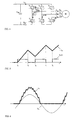
- FIG. 6 presents the flow of the phase current explained above during a longer period of time.
- U U is the virtual U phase voltage of the permanent magnet motor (illustrating the internal electromotive force of the motor; the actual terminal voltage during the operation of the frequency converter is known to be pulse-like), and -i U is the negation of the same phase current.
- the lower branch control pulses are similar in length in connection with start-up and long enough for current to clearly flow, yet not long enough for the current to reach dangerous levels during a single pulse.
- the terminal voltage of the permanent magnet motor is proportional to the speed of rotation, it may be advantageous to change the length of the pulse according to the measured current.
- the measured phase current also represents information of the positive alternation of the phase voltage.
- phase current and phase voltage achieved according to the invention can be utilized in various ways. For instance, the start-up of the frequency converter can be prevented completely when the motor is rotating. It is also possible, during a few motor rotation cycles, to repeat the above function, e.g., in two phases, which provides information on the sequence of these phase voltages, and combined with the measured alternation time, this provides information on the direction and speed of rotation. Based on this information, it is possible to start the frequency converter directly to a rotating motor (known as "flying start").
Landscapes
- Engineering & Computer Science (AREA)
- Power Engineering (AREA)
- Control Of Ac Motors In General (AREA)
- Inverter Devices (AREA)
- Control Of Motors That Do Not Use Commutators (AREA)
Description
- This invention relates to a method and apparatus for starting a frequency converter when a permanent magnet motor whose rotor is rotating during the start-up is connected to it. The method and equipment particularly relate to a frequency converter whose current transducer is located in the DC intermediate circuit and whose driving power to the diverter switches of the load bridge upper branch is input with the so-called bootstrap method.
- Especially with low-power frequency converters, the competitive situation in the market makes it a necessity to seek the most simple and cost-efficient technical solutions possible that will achieve the required performance. For example, motor current can be measured using only one current transducer located in the DC intermediate circuit instead of three current transformers placed in the output phases in accordance with
FI 116337 FI 119493 US Patent 5408150 . - Motors equipped with a rotor with permanent magnets have recently become more common due to their low costs in low-power applications and accurately adjustable rotation speed. (A permanent magnet machine is a synchronous machine by nature, with no slip, unlike the most common motor type, the short circuit motor.) A frequency converter is known to be the most advantageous way of adjusting the speed of rotation.
- In some cases, the motor can rotate even if the coupled frequency converter is in the stopped state. For instance, in an air conditioning application, a weak gravitational air flow can result in a force that rotates a fan located in an air duct. In the same way as several motors rotate a long conveyor belt, a motor whose supplying frequency converter has been stopped for some reason rotates. The terminal voltage of a permanent magnet motor is known to be directly proportional to the speed of rotation.
- When the driving power to the diverter switches of the frequency converter's upper branch diverter switches is supplied with the bootstrap method, operation must be started by first switching the lower branch diverter switch conductive to supply control voltage to the upper branch. This may result in a short circuit between the phases when the permanent magnet motor coupled to the frequency converter is rotating. When the motor's current is measured using only one transducer located in the DC intermediate circuit, this kind of a short-circuit current is not necessarily observed at all, which might result in damage to the device.
- Start-up of a frequency converter to a rotating motor usually requires special measures to prevent an uncontrolled overload current pulse. Patent
FI 113106 -
JP 2001275366 - With the method of
JP 2001275366 JP 2003061385 - The purpose of this invention is to achieve a novel start-up method of a frequency converter that avoids the disadvantages mentioned above and enables the safe start-up of a frequency converter equipped with one DC current transducer and upper branch bootstrap driving power supply to a rotating permanent magnet motor. This purpose is achieved by the method and apparatus according to the invention, characterized by the characterizing parts of the
independent claims 1 and 7. Other preferred embodiments of the invention are covered by the dependent claims. - In the method of the invention, one diverter switch in the lower branch of the load bridge is controlled to a conductive state for a short time, such as for 200µs. The time is so short that the short-circuit current of a possibly rotating permanent magnet motor will not have time to increase to a dangerous level, yet long enough in terms of current measurement. When the diverter switch is returned to a non-conductive state, any short-circuit current, which is inductive as is known, will continue its passage via the corresponding zero diode of the upper branch and return to the motor through the capacitor of the DC intermediate circuit and zero diodes of other phases in the lower branch. Therefore, the path of current goes via the current transducer placed in the DC intermediate circuit, from which the control system of the device receives information about a short-circuit current, which is also an indication of the motor coupled to the frequency converter rotating.
- According to the invention, the above-mentioned control pulses are continued for the desired duration, which yields information also on the motor's speed of rotation; when the phase current is positive, current pulses are flowing, whereas there are no current pulses flowing during the negative alternation. Correspondingly, when control pulses are issued to every phase, or at least two phases, this yields information on the phase sequence, i.e., the direction of rotation.
- The invention makes it possible to safely start a rotating permanent magnet motor with a frequency converter whose current measurement and diverter switch driving power supply solutions are technically limited due to cost-related reasons.
- Below the invention appears a more detailed explanation using examples with references to the enclosed figures, wherein
-
Figure 1 presents the main circuit of frequency converter use and current transducer placed in the intermediate circuit; -
Figure 2 presents the diverter switch driving power supply solution; -
Figure 3 presents the voltages of a three-phase system; -
Figure 4 presents the path of short-circuit current in a frequency converter; -
Figure 5 presents short-circuit current and lower branch switch controls; and -
Figure 6 presents short-circuit current during the entire phase. -
Figure 1 presents a known three-phase PWM frequency converter main circuit, with a power line, whose connections are L1 - L3, current-filtering AC restrictor Lac (instead of which a restrictor placed in the DC intermediate circuit is commonly used, or particularly in low-power devices the restrictor may be omitted altogether),network bridge 10 comprising of diodes D11 - D16 to rectify the three-phase alternating current of the power line into the direct current of the direct current intermediate circuit, filtered with the capacitor CDC,load bridge 11 comprising of a phase switch realized with power semiconductors that converts the direct current UDC of the intermediate circuit into a three-phase output voltage Uu, Uv, Uw, andcontrol unit 12. The phase switches of the load bridge comprise of controllable upper- and lower-branch power semiconductor switches, preferably IGBTs V1 - V6 and zero diodes D1 - D6 connected parallel to them. The phase switch connects the output phase either to the +UDC (top position) or -UDC (low position) rail. The control pulses of the power semiconductor switches are formed in the so-called modulator of the control unit. - This invention relates to a system wherein motor power is measured with a current transducer placed in the DC intermediate circuit, such as shunt resistor RDC, which may be located in the -DDC branch as presented in the figure or alternatively in the +UDC branch or in series with filter capacitor CDC of the DC intermediate circuit. Current measurement according to the figure is known to yield information on motor currents according to the position of the phase switches. Table 1 presents the dependencies between all of the different switch positions and phase currents seen in the iDC signal (the positive direction of the currents is configured according to
Figure 1 towards the motor, position 0 of phase switches U, V, W means that the IGBT of the phase switch lower branch has been controlled to a conductive state and 1 correspondingly means upper branch control):TABLE 1 U V W iDC U V W iDC 0 0 0 0 1 1 0 - iw 1 0 0 iU 0 1 1 - iU 0 1 0 iV 1 0 1 - iV 0 0 1 iW 1 1 1 0 -
Figure 2 presents a known so-called bootstrap connection, which is a preferred way of supplying the driving power required by the upper branch power semiconductor switch (V1). In accordance with the bootstrap idea, when lower branch diverter switch V4 conducts, the upper branch switch's emitter potential E1 is close to the -UDC potential, in which case the upper branch control circuit GD1 auxiliary voltage filter capacitor C1 charges through the bootstrap diode DG1 to nearly the same voltage UGD used for supplying the lower branch control circuit GD4. Full controllability of the phase switch, i.e., the possibility to control both the upper and lower branch power semiconductor switches conductive therefore requires that the control start from the lower branch and that the switching frequency, i.e., the frequency with which the upper and lower branch control pulses alternate, is high enough for the voltage in the upper branch capacitor C1 to remain sufficient at all times. -
Figures 3 - 5 are related to illustrating the basics of the method of the invention.Figure 3 presents a three-phase sine curve, such as connection voltage UU, UV, UW of the rotating permanent magnet motor when the connected frequency converter is in the stopped state. - Let us assume that control of the frequency converter according to the invention begins at moment to, when the voltage of the U phase is positive and voltages of the other phases are negative. Let us further assume, as described above, that the lower branch diverter switch of the U phase is first controlled to be conductive. Therefore, the short circuit presented in
Figure 4 is established through all conductive lower branch switches. According toFigure 4 , the short-circuit current flows through the U phase lower branch IGBT's V4 (current path 1) and zero diodes of the lower branch of other phases. The components involved in the flow of the current have been drawn with a continuous line in the figure to illustrate the situation; those not involved are shown with a broken line. InFigure 5 , which presents the U phase lower branch diverter switch V4 control signal V4/G and U phase current negation -iU, the same situation is portrayed by the time interval t0 - t1. It is easy to see inFigure 4 that as the motor current flows only via the lower branch, current transducer RDC, does not detect any current flow. - Let us further assume that control of the V4 switch is stopped at moment t1 according to
Figure 5 , wherein the inductive short-circuit current of the U phase turns to flow via the upper branch zero diode (current path 2 inFigure 4 ). The currents of the other phases continue to flow along the previous path through the lower branches as the zero diodes remain conductive and the voltages of these phases remain negative. As the U phase is now in a different position from the other phases, its current is shown in the current transducer according to Table 1 (U V W = 1 0 0, so iDC = iU). The situation continues during the time interval t1 - t2 presented inFigure 5 , wherein the current supplied by the motor decreases as inductive energy is discharged into the intermediate circuit. - At moment t2, the U phase lower branch switch is returned to a conductive state, again forming a short-circuit due to which the motor's current begins to increase again. The operation continues in this way for as long as desired. As mentioned above, the DC intermediate circuit current transducer RDC sees a sample of the motor's current only when the phase switches are in different positions. In order to achieve a coherent view of the output currents, the frequency converter's control unit usually interpolates the results between samples.
-
Figure 6 presents the flow of the phase current explained above during a longer period of time. In the figure, UU is the virtual U phase voltage of the permanent magnet motor (illustrating the internal electromotive force of the motor; the actual terminal voltage during the operation of the frequency converter is known to be pulse-like), and -iU is the negation of the same phase current. According to the invention, the lower branch control pulses are similar in length in connection with start-up and long enough for current to clearly flow, yet not long enough for the current to reach dangerous levels during a single pulse. As the terminal voltage of the permanent magnet motor is proportional to the speed of rotation, it may be advantageous to change the length of the pulse according to the measured current. This can be realized, e.g., by beginning with a short pulse, such as approximately 200 µs, and if the measured current is too low to make accurate conclusions, the length of the pulse is increased as necessary. This way, the higher the phase voltage, the higher the current increases during the short circuits. Furthermore, if the phase voltage is negative, no short-circuit current flows in the first place. Thus, when the lower branch of a single phase is initially controlled according to the invention, the measured phase current also represents information of the positive alternation of the phase voltage. - Information about phase current and phase voltage achieved according to the invention can be utilized in various ways. For instance, the start-up of the frequency converter can be prevented completely when the motor is rotating. It is also possible, during a few motor rotation cycles, to repeat the above function, e.g., in two phases, which provides information on the sequence of these phase voltages, and combined with the measured alternation time, this provides information on the direction and speed of rotation. Based on this information, it is possible to start the frequency converter directly to a rotating motor (known as "flying start").
- To those skilled in the art, it is obvious that the various embodiments of the invention are not exclusively limited to the examples provided but that they may vary within the limits of the patent claims presented below.
Claims (12)
- A method to start a frequency converter equipped with a direct current intermediate circuit, when a permanent magnet motor whose rotor is rotating at the start-up time is connected to it,
wherein the frequency converter has a network bridge (10) and load bridge (11), and the load bridge has controllable power semiconductor switches of the upper and lower branch (V1 - V6) and parallel connected zero diodes (D1 - D6), and a direct current intermediate circuit between them,
and the said frequency converter uses a current transducer (RDC) placed in the direct current intermediate circuit, and the analogue current signal composed by it features samples of the measured output currents, and
the diverter switches of the frequency converter's upper branch are controlled using the bootstrap method,
characterized in that
start-up is initiated by controlling the controllable power semiconductor switch of the lower branch of one output phase to a conductive state for one or several switching periods, preferably 200 µs, corresponding to the switching frequency, by measuring the output current by the current transducer during the non-conductive states (t1, t2; t3, t4), and by determining the polarity of the corresponding phase voltage (Uu, Uv, Uw) based on whether the current (iU, iV, iW) is flowing or not. - Method according to claim 1,
characterized in that
upon the current transducer detecting that the output current deviates from zero during the time between the conductive controls, start-up of the frequency converter is prevented. - Method according to claim 1,
characterized in that
upon the current transducer detecting that the output current deviates from zero during the time between the conductive controls, the conductive controls are continued until there is no current flow. - Method according to claims 1 or 3,
characterized in that
the time during which flow of current is detected is used as the indicator of the positive alternation of the phase voltage of the rotating permanent magnet motor. - Method according to claims 1, 3 or 4,
characterized in that
controls of the lower branch's controllable power semiconductor switches are performed in at least two phases. - Method according to claim 5,
characterized in that
the times during which current is detected to flow in at least two phases whose controllable lower branch power semiconductor switches are controlled are used as an indicator of the phase sequence of the rotating permanent magnet motor. - An apparatus to start a frequency converter equipped with a direct current intermediate circuit, when a permanent magnet motor whose rotor is rotating at the start-up time is connected to it,
wherein the frequency converter has a control unit, network bridge (10) and load bridge (11), and the load bridge has controllable power semiconductor switches of the upper and lower branch (V1 - V6) and parallel connected zero diodes (D1 - D6), and a direct current intermediate circuit between them,
and the said frequency converter has a current transducer (RDC) placed in the direct current intermediate circuit, and the analogue current signal composed by it features samples of the measured output currents, and
the said control unit is adapted to control the diverter switches of the frequency converter's upper branch with the bootstrap method,
characterized in that
the control unit is adapted to initiate start-up by controlling the controllable power semiconductor switch of the lower branch of one output phase to a conductive state for one or several switching periods, preferably 200 µs, corresponding to the switching frequency, to measure the output current by the current transducer during the non-conductive states (t1, t2; t3, t4), and by determining the polarity of the corresponding phase voltage (Uu, Uv, Uw) based on whether the current (iU, iV, iW) is flowing or not. - Apparatus according to claim 7,
characterized in that the control unit is adapted so that
upon the current transducer detecting that the output current deviates from zero during the time between the conductive controls, the start-up of the frequency converter is prevented. - Apparatus according to claim 7,
characterized in that the control unit is adapted so that
upon the current transducer detecting that the output current deviates from zero during the time between the conductive controls, the conductive controls are continued until there is no current flow. - Apparatus according to claims 7 or 9,
characterized in that the control unit is adapted so that
the time during which flow of current is detected flow is used as the indicator of the positive alternation of the phase voltage of the rotating permanent magnet motor. - Apparatus according to claims 7, 9 or 10,
characterized in that the control unit is adapted so that
controls of the lower branch's controllable power semiconductor switches are performed in at least two phases. - Apparatus according to claim 11,
characterized in that the control unit is adapted so that
the times during which current is detected to flow in at least two phases whose controllable lower branch power semiconductor switches are controlled are used as an indicator of the phase sequence of the rotating permanent magnet motor.
Applications Claiming Priority (1)
| Application Number | Priority Date | Filing Date | Title |
|---|---|---|---|
| FI20095361A FI122159B (en) | 2009-04-02 | 2009-04-02 | Starting a frequency converter |
Publications (2)
| Publication Number | Publication Date |
|---|---|
| EP2237406A1 EP2237406A1 (en) | 2010-10-06 |
| EP2237406B1 true EP2237406B1 (en) | 2012-05-30 |
Family
ID=40590244
Family Applications (1)
| Application Number | Title | Priority Date | Filing Date |
|---|---|---|---|
| EP10157461A Not-in-force EP2237406B1 (en) | 2009-04-02 | 2010-03-24 | Frequency converter start-up |
Country Status (5)
| Country | Link |
|---|---|
| US (1) | US8350506B2 (en) |
| EP (1) | EP2237406B1 (en) |
| CN (1) | CN101567623B (en) |
| DK (1) | DK2237406T3 (en) |
| FI (1) | FI122159B (en) |
Families Citing this family (10)
| Publication number | Priority date | Publication date | Assignee | Title |
|---|---|---|---|---|
| DE102012012602A1 (en) * | 2011-07-14 | 2013-01-17 | Volkswagen Aktiengesellschaft | Brushless direct current (DC) machine e.g. brushless DC motor for e.g. vehicle, has several strands (STI) electrically isolated from each other |
| GB2497595B (en) * | 2011-12-16 | 2013-12-11 | Control Tech Ltd | Variable switching frequency power converter |
| CN103051204A (en) * | 2012-12-14 | 2013-04-17 | 台州富凌电气有限公司 | Special frequency converter for industrial vibrating rod |
| TWI531151B (en) * | 2012-12-27 | 2016-04-21 | 台達電子工業股份有限公司 | Modularized control circuit of fan motor and method for operating the same |
| WO2014186772A1 (en) * | 2013-05-16 | 2014-11-20 | Keyssa, Inc. | Extremely high frequency converter |
| CN106998166B (en) * | 2017-05-13 | 2020-03-27 | 上海建东科技有限公司 | Soft start method and control device for permanent magnet synchronous motor |
| CN107248819A (en) * | 2017-06-06 | 2017-10-13 | 郁清林 | A kind of 3300v frequency converters of use phase voltage converter technique |
| WO2019020185A1 (en) * | 2017-07-27 | 2019-01-31 | Vacon Oy | Motor drive adaptation |
| US10581357B2 (en) * | 2018-05-11 | 2020-03-03 | Abb Schweiz Ag | Rotating direct current power supply for synchronous machines |
| DE102019206751B4 (en) * | 2019-05-09 | 2021-03-25 | Schmidhauser Ag | frequency converter |
Family Cites Families (26)
| Publication number | Priority date | Publication date | Assignee | Title |
|---|---|---|---|---|
| JPS55111677A (en) * | 1979-02-20 | 1980-08-28 | Toshiba Corp | System for starting commutatorless motor |
| EP0177114B1 (en) * | 1984-09-05 | 1992-04-22 | Kabushiki Kaisha Meidensha | Method and system for reconnecting inverter to rotating motors |
| US4746850A (en) * | 1987-02-12 | 1988-05-24 | Westinghouse Electric Corp. | Start-up system for a synchronous motor drive |
| US4743815A (en) * | 1987-09-01 | 1988-05-10 | Emerson Electric Co. | Brushless permanent magnet motor system |
| US5408150A (en) | 1992-06-04 | 1995-04-18 | Linear Technology Corporation | Circuit for driving two power mosfets in a half-bridge configuration |
| US5483140A (en) * | 1993-10-01 | 1996-01-09 | Wisconsin Alumni Research Foundation | Thyristor based DC link current source power conversion system for motor driven operation |
| US5506484A (en) * | 1994-06-10 | 1996-04-09 | Westinghouse Electric Corp. | Digital pulse width modulator with integrated test and control |
| JP3400917B2 (en) | 1996-08-07 | 2003-04-28 | 株式会社日立製作所 | Start control method for commutatorless motor |
| US6285146B1 (en) * | 1998-08-07 | 2001-09-04 | Nidec America Corporation | Apparatus and method of regulating the speed of a brushless DC motor |
| SE513764C2 (en) | 1998-10-16 | 2000-10-30 | Atlas Copco Controls Ab | Method for restarting a permanent magnet synchronous motor during residual rotation |
| JP3716702B2 (en) | 2000-03-27 | 2005-11-16 | ダイキン工業株式会社 | How to charge the bootstrap capacitor |
| JP2002058254A (en) * | 2000-08-08 | 2002-02-22 | Matsushita Electric Ind Co Ltd | Air conditioner current detection circuit |
| FI113106B (en) | 2001-06-14 | 2004-02-27 | Abb Oy | Method for coupling an inverter to alternating voltage |
| JP2003061385A (en) * | 2001-08-13 | 2003-02-28 | Matsushita Electric Ind Co Ltd | Position Sensorless Controller for Permanent Magnet Synchronous Motor |
| JP4458794B2 (en) | 2003-08-12 | 2010-04-28 | 株式会社東芝 | Motor control device |
| FI116337B (en) | 2003-12-19 | 2005-10-31 | Abb Oy | A method for determining the output currents in a frequency converter |
| US7190208B2 (en) * | 2004-04-08 | 2007-03-13 | International Rectifier Corporation | Self-oscillating full bridge driver IC |
| KR101041076B1 (en) * | 2004-12-17 | 2011-06-13 | 삼성전자주식회사 | Starting control method of brushless DC motor |
| US7652441B2 (en) | 2005-07-01 | 2010-01-26 | International Rectifier Corporation | Method and system for starting a sensorless motor |
| JP5193421B2 (en) * | 2005-12-09 | 2013-05-08 | 日立アプライアンス株式会社 | Electric motor control device |
| JP5025142B2 (en) | 2006-02-27 | 2012-09-12 | 株式会社東芝 | Motor control device |
| FI118583B (en) * | 2006-06-01 | 2007-12-31 | Vacon Oyj | Drive current measurement |
| FI119493B (en) | 2006-12-21 | 2008-11-28 | Vacon Oyj | Arrangements for measuring the current through a frequency converter |
| US7948204B2 (en) * | 2007-04-13 | 2011-05-24 | International Rectifier Corporation | Sensorless speed detection of a PM brushless motor with phase terminals shorted |
| US8716655B2 (en) | 2009-07-02 | 2014-05-06 | Tricorntech Corporation | Integrated ion separation spectrometer |
| JP5150585B2 (en) * | 2009-08-28 | 2013-02-20 | 株式会社日立産機システム | Permanent magnet synchronous motor drive device |
-
2009
- 2009-04-02 FI FI20095361A patent/FI122159B/en not_active IP Right Cessation
- 2009-05-26 CN CN2009101430684A patent/CN101567623B/en not_active Expired - Fee Related
-
2010
- 2010-03-24 EP EP10157461A patent/EP2237406B1/en not_active Not-in-force
- 2010-03-24 DK DK10157461.4T patent/DK2237406T3/en active
- 2010-04-01 US US12/752,495 patent/US8350506B2/en not_active Expired - Fee Related
Also Published As
| Publication number | Publication date |
|---|---|
| CN101567623B (en) | 2012-08-22 |
| US20100253256A1 (en) | 2010-10-07 |
| DK2237406T3 (en) | 2012-09-10 |
| CN101567623A (en) | 2009-10-28 |
| FI122159B (en) | 2011-09-15 |
| EP2237406A1 (en) | 2010-10-06 |
| FI20095361L (en) | 2010-10-03 |
| FI20095361A0 (en) | 2009-04-02 |
| US8350506B2 (en) | 2013-01-08 |
Similar Documents
| Publication | Publication Date | Title |
|---|---|---|
| US8350506B2 (en) | Frequency converter start-up | |
| CN112242831B (en) | Gate driver circuit and method of detecting a short circuit event in an inverter leg | |
| US11196379B2 (en) | System for detection and algorithmic avoidance of isolation failures in electric motors | |
| EP0397514A2 (en) | Bridge inverters and the control thereof | |
| RU2453981C2 (en) | Method and device for measuring excitation current in brishless machines | |
| US7239099B2 (en) | Circuit configuration and method for controlling an electric motor, in particular of a washing machine | |
| US10158307B2 (en) | Method and device for determining phase currents and an excitation current of an electrical machine, and motor system | |
| KR101813916B1 (en) | Method and apparatus for determining a zero crossing of a phase current of an electronically commutated electrical machine, in particular for determining a rotor position of the electrical machine | |
| JP2017103993A (en) | Motor control device | |
| JP2018038114A (en) | Motor controller | |
| EP2453571B1 (en) | Converter and method for driving an electric AC machine | |
| WO1998021816A1 (en) | Method and apparatus for electronically commuting an electric motor | |
| CN111193460B (en) | Variable frequency drive with integrated front-end rectifier and bypass | |
| EP2940846B1 (en) | A method of initiating a regenerative converter and a regenerative converter | |
| US20090315491A1 (en) | Electric motor | |
| EP0994561B1 (en) | Method for restarting a synchronous permanent magnet motor still rotating | |
| EP1174998B1 (en) | Brushless motor,method and circuit for its control | |
| US11843313B2 (en) | Method and apparatus for controlling electric motors | |
| EP0908002B1 (en) | Control apparatus and method for electric motor-generators | |
| FI121205B (en) | Electric motor control arrangement | |
| KR20210085940A (en) | Power converting system | |
| JP2018050399A (en) | Field winding type synchronous motor and control method thereof | |
| US12176827B2 (en) | Inverter with leg current detection | |
| JP6596358B2 (en) | Field winding type synchronous motor | |
| FI121293B (en) | Braking function control |
Legal Events
| Date | Code | Title | Description |
|---|---|---|---|
| PUAI | Public reference made under article 153(3) epc to a published international application that has entered the european phase |
Free format text: ORIGINAL CODE: 0009012 |
|
| AK | Designated contracting states |
Kind code of ref document: A1 Designated state(s): AT BE BG CH CY CZ DE DK EE ES FI FR GB GR HR HU IE IS IT LI LT LU LV MC MK MT NL NO PL PT RO SE SI SK SM TR |
|
| AX | Request for extension of the european patent |
Extension state: AL BA ME RS |
|
| 17P | Request for examination filed |
Effective date: 20110405 |
|
| 17Q | First examination report despatched |
Effective date: 20110823 |
|
| GRAP | Despatch of communication of intention to grant a patent |
Free format text: ORIGINAL CODE: EPIDOSNIGR1 |
|
| RIC1 | Information provided on ipc code assigned before grant |
Ipc: H03K 17/56 20060101ALI20120117BHEP Ipc: H03K 17/06 20060101ALI20120117BHEP Ipc: H02P 6/14 20060101AFI20120117BHEP Ipc: H02M 7/5387 20070101ALI20120117BHEP Ipc: H02P 6/16 20060101ALI20120117BHEP Ipc: H02P 27/08 20060101ALI20120117BHEP Ipc: H02M 1/36 20070101ALI20120117BHEP |
|
| GRAS | Grant fee paid |
Free format text: ORIGINAL CODE: EPIDOSNIGR3 |
|
| GRAA | (expected) grant |
Free format text: ORIGINAL CODE: 0009210 |
|
| AK | Designated contracting states |
Kind code of ref document: B1 Designated state(s): AT BE BG CH CY CZ DE DK EE ES FI FR GB GR HR HU IE IS IT LI LT LU LV MC MK MT NL NO PL PT RO SE SI SK SM TR |
|
| REG | Reference to a national code |
Ref country code: GB Ref legal event code: FG4D |
|
| REG | Reference to a national code |
Ref country code: CH Ref legal event code: EP |
|
| REG | Reference to a national code |
Ref country code: AT Ref legal event code: REF Ref document number: 560456 Country of ref document: AT Kind code of ref document: T Effective date: 20120615 |
|
| REG | Reference to a national code |
Ref country code: IE Ref legal event code: FG4D |
|
| REG | Reference to a national code |
Ref country code: CH Ref legal event code: NV Representative=s name: KIRKER & CIE S.A. |
|
| REG | Reference to a national code |
Ref country code: DE Ref legal event code: R096 Ref document number: 602010001741 Country of ref document: DE Effective date: 20120802 |
|
| REG | Reference to a national code |
Ref country code: DK Ref legal event code: T3 |
|
| REG | Reference to a national code |
Ref country code: NL Ref legal event code: VDEP Effective date: 20120530 |
|
| REG | Reference to a national code |
Ref country code: LT Ref legal event code: MG4D Effective date: 20120530 |
|
| PG25 | Lapsed in a contracting state [announced via postgrant information from national office to epo] |
Ref country code: SE Free format text: LAPSE BECAUSE OF FAILURE TO SUBMIT A TRANSLATION OF THE DESCRIPTION OR TO PAY THE FEE WITHIN THE PRESCRIBED TIME-LIMIT Effective date: 20120530 Ref country code: IS Free format text: LAPSE BECAUSE OF FAILURE TO SUBMIT A TRANSLATION OF THE DESCRIPTION OR TO PAY THE FEE WITHIN THE PRESCRIBED TIME-LIMIT Effective date: 20120930 Ref country code: LT Free format text: LAPSE BECAUSE OF FAILURE TO SUBMIT A TRANSLATION OF THE DESCRIPTION OR TO PAY THE FEE WITHIN THE PRESCRIBED TIME-LIMIT Effective date: 20120530 Ref country code: CY Free format text: LAPSE BECAUSE OF FAILURE TO SUBMIT A TRANSLATION OF THE DESCRIPTION OR TO PAY THE FEE WITHIN THE PRESCRIBED TIME-LIMIT Effective date: 20120530 Ref country code: NO Free format text: LAPSE BECAUSE OF FAILURE TO SUBMIT A TRANSLATION OF THE DESCRIPTION OR TO PAY THE FEE WITHIN THE PRESCRIBED TIME-LIMIT Effective date: 20120830 Ref country code: FI Free format text: LAPSE BECAUSE OF FAILURE TO SUBMIT A TRANSLATION OF THE DESCRIPTION OR TO PAY THE FEE WITHIN THE PRESCRIBED TIME-LIMIT Effective date: 20120530 |
|
| REG | Reference to a national code |
Ref country code: AT Ref legal event code: MK05 Ref document number: 560456 Country of ref document: AT Kind code of ref document: T Effective date: 20120530 |
|
| PG25 | Lapsed in a contracting state [announced via postgrant information from national office to epo] |
Ref country code: SI Free format text: LAPSE BECAUSE OF FAILURE TO SUBMIT A TRANSLATION OF THE DESCRIPTION OR TO PAY THE FEE WITHIN THE PRESCRIBED TIME-LIMIT Effective date: 20120530 Ref country code: LV Free format text: LAPSE BECAUSE OF FAILURE TO SUBMIT A TRANSLATION OF THE DESCRIPTION OR TO PAY THE FEE WITHIN THE PRESCRIBED TIME-LIMIT Effective date: 20120530 Ref country code: HR Free format text: LAPSE BECAUSE OF FAILURE TO SUBMIT A TRANSLATION OF THE DESCRIPTION OR TO PAY THE FEE WITHIN THE PRESCRIBED TIME-LIMIT Effective date: 20120530 Ref country code: GR Free format text: LAPSE BECAUSE OF FAILURE TO SUBMIT A TRANSLATION OF THE DESCRIPTION OR TO PAY THE FEE WITHIN THE PRESCRIBED TIME-LIMIT Effective date: 20120831 |
|
| PG25 | Lapsed in a contracting state [announced via postgrant information from national office to epo] |
Ref country code: BE Free format text: LAPSE BECAUSE OF FAILURE TO SUBMIT A TRANSLATION OF THE DESCRIPTION OR TO PAY THE FEE WITHIN THE PRESCRIBED TIME-LIMIT Effective date: 20120530 |
|
| PG25 | Lapsed in a contracting state [announced via postgrant information from national office to epo] |
Ref country code: RO Free format text: LAPSE BECAUSE OF FAILURE TO SUBMIT A TRANSLATION OF THE DESCRIPTION OR TO PAY THE FEE WITHIN THE PRESCRIBED TIME-LIMIT Effective date: 20120530 Ref country code: NL Free format text: LAPSE BECAUSE OF FAILURE TO SUBMIT A TRANSLATION OF THE DESCRIPTION OR TO PAY THE FEE WITHIN THE PRESCRIBED TIME-LIMIT Effective date: 20120530 Ref country code: EE Free format text: LAPSE BECAUSE OF FAILURE TO SUBMIT A TRANSLATION OF THE DESCRIPTION OR TO PAY THE FEE WITHIN THE PRESCRIBED TIME-LIMIT Effective date: 20120530 Ref country code: SK Free format text: LAPSE BECAUSE OF FAILURE TO SUBMIT A TRANSLATION OF THE DESCRIPTION OR TO PAY THE FEE WITHIN THE PRESCRIBED TIME-LIMIT Effective date: 20120530 Ref country code: CZ Free format text: LAPSE BECAUSE OF FAILURE TO SUBMIT A TRANSLATION OF THE DESCRIPTION OR TO PAY THE FEE WITHIN THE PRESCRIBED TIME-LIMIT Effective date: 20120530 Ref country code: AT Free format text: LAPSE BECAUSE OF FAILURE TO SUBMIT A TRANSLATION OF THE DESCRIPTION OR TO PAY THE FEE WITHIN THE PRESCRIBED TIME-LIMIT Effective date: 20120530 |
|
| PG25 | Lapsed in a contracting state [announced via postgrant information from national office to epo] |
Ref country code: PT Free format text: LAPSE BECAUSE OF FAILURE TO SUBMIT A TRANSLATION OF THE DESCRIPTION OR TO PAY THE FEE WITHIN THE PRESCRIBED TIME-LIMIT Effective date: 20121001 Ref country code: PL Free format text: LAPSE BECAUSE OF FAILURE TO SUBMIT A TRANSLATION OF THE DESCRIPTION OR TO PAY THE FEE WITHIN THE PRESCRIBED TIME-LIMIT Effective date: 20120530 Ref country code: IT Free format text: LAPSE BECAUSE OF FAILURE TO SUBMIT A TRANSLATION OF THE DESCRIPTION OR TO PAY THE FEE WITHIN THE PRESCRIBED TIME-LIMIT Effective date: 20120530 |
|
| PLBE | No opposition filed within time limit |
Free format text: ORIGINAL CODE: 0009261 |
|
| STAA | Information on the status of an ep patent application or granted ep patent |
Free format text: STATUS: NO OPPOSITION FILED WITHIN TIME LIMIT |
|
| PG25 | Lapsed in a contracting state [announced via postgrant information from national office to epo] |
Ref country code: ES Free format text: LAPSE BECAUSE OF FAILURE TO SUBMIT A TRANSLATION OF THE DESCRIPTION OR TO PAY THE FEE WITHIN THE PRESCRIBED TIME-LIMIT Effective date: 20120910 |
|
| 26N | No opposition filed |
Effective date: 20130301 |
|
| REG | Reference to a national code |
Ref country code: DE Ref legal event code: R097 Ref document number: 602010001741 Country of ref document: DE Effective date: 20130301 |
|
| PG25 | Lapsed in a contracting state [announced via postgrant information from national office to epo] |
Ref country code: BG Free format text: LAPSE BECAUSE OF FAILURE TO SUBMIT A TRANSLATION OF THE DESCRIPTION OR TO PAY THE FEE WITHIN THE PRESCRIBED TIME-LIMIT Effective date: 20120830 |
|
| PG25 | Lapsed in a contracting state [announced via postgrant information from national office to epo] |
Ref country code: MC Free format text: LAPSE BECAUSE OF NON-PAYMENT OF DUE FEES Effective date: 20130331 |
|
| REG | Reference to a national code |
Ref country code: IE Ref legal event code: MM4A |
|
| PG25 | Lapsed in a contracting state [announced via postgrant information from national office to epo] |
Ref country code: IE Free format text: LAPSE BECAUSE OF NON-PAYMENT OF DUE FEES Effective date: 20130324 |
|
| PG25 | Lapsed in a contracting state [announced via postgrant information from national office to epo] |
Ref country code: MT Free format text: LAPSE BECAUSE OF FAILURE TO SUBMIT A TRANSLATION OF THE DESCRIPTION OR TO PAY THE FEE WITHIN THE PRESCRIBED TIME-LIMIT Effective date: 20120530 |
|
| REG | Reference to a national code |
Ref country code: FR Ref legal event code: PLFP Year of fee payment: 6 |
|
| PGFP | Annual fee paid to national office [announced via postgrant information from national office to epo] |
Ref country code: CH Payment date: 20150319 Year of fee payment: 6 Ref country code: DK Payment date: 20150319 Year of fee payment: 6 |
|
| PG25 | Lapsed in a contracting state [announced via postgrant information from national office to epo] |
Ref country code: SM Free format text: LAPSE BECAUSE OF FAILURE TO SUBMIT A TRANSLATION OF THE DESCRIPTION OR TO PAY THE FEE WITHIN THE PRESCRIBED TIME-LIMIT Effective date: 20120530 |
|
| PGFP | Annual fee paid to national office [announced via postgrant information from national office to epo] |
Ref country code: FR Payment date: 20150319 Year of fee payment: 6 Ref country code: GB Payment date: 20150319 Year of fee payment: 6 |
|
| PG25 | Lapsed in a contracting state [announced via postgrant information from national office to epo] |
Ref country code: TR Free format text: LAPSE BECAUSE OF FAILURE TO SUBMIT A TRANSLATION OF THE DESCRIPTION OR TO PAY THE FEE WITHIN THE PRESCRIBED TIME-LIMIT Effective date: 20120530 |
|
| PG25 | Lapsed in a contracting state [announced via postgrant information from national office to epo] |
Ref country code: MK Free format text: LAPSE BECAUSE OF FAILURE TO SUBMIT A TRANSLATION OF THE DESCRIPTION OR TO PAY THE FEE WITHIN THE PRESCRIBED TIME-LIMIT Effective date: 20120530 Ref country code: HU Free format text: LAPSE BECAUSE OF FAILURE TO SUBMIT A TRANSLATION OF THE DESCRIPTION OR TO PAY THE FEE WITHIN THE PRESCRIBED TIME-LIMIT; INVALID AB INITIO Effective date: 20100324 Ref country code: LU Free format text: LAPSE BECAUSE OF NON-PAYMENT OF DUE FEES Effective date: 20130324 |
|
| REG | Reference to a national code |
Ref country code: DE Ref legal event code: R082 Ref document number: 602010001741 Country of ref document: DE Representative=s name: FROHWITTER PATENT- UND RECHTSANWAELTE, DE Ref country code: DE Ref legal event code: R081 Ref document number: 602010001741 Country of ref document: DE Owner name: VACON OY, FI Free format text: FORMER OWNER: VACON OYJ, VAASA, FI |
|
| REG | Reference to a national code |
Ref country code: DK Ref legal event code: EBP Effective date: 20160331 |
|
| REG | Reference to a national code |
Ref country code: CH Ref legal event code: PL |
|
| GBPC | Gb: european patent ceased through non-payment of renewal fee |
Effective date: 20160324 |
|
| REG | Reference to a national code |
Ref country code: FR Ref legal event code: ST Effective date: 20161130 |
|
| PG25 | Lapsed in a contracting state [announced via postgrant information from national office to epo] |
Ref country code: CH Free format text: LAPSE BECAUSE OF NON-PAYMENT OF DUE FEES Effective date: 20160331 Ref country code: FR Free format text: LAPSE BECAUSE OF NON-PAYMENT OF DUE FEES Effective date: 20160331 Ref country code: LI Free format text: LAPSE BECAUSE OF NON-PAYMENT OF DUE FEES Effective date: 20160331 Ref country code: GB Free format text: LAPSE BECAUSE OF NON-PAYMENT OF DUE FEES Effective date: 20160324 |
|
| PG25 | Lapsed in a contracting state [announced via postgrant information from national office to epo] |
Ref country code: DK Free format text: LAPSE BECAUSE OF NON-PAYMENT OF DUE FEES Effective date: 20160331 |
|
| PGFP | Annual fee paid to national office [announced via postgrant information from national office to epo] |
Ref country code: DE Payment date: 20200310 Year of fee payment: 11 |
|
| REG | Reference to a national code |
Ref country code: DE Ref legal event code: R119 Ref document number: 602010001741 Country of ref document: DE |
|
| PG25 | Lapsed in a contracting state [announced via postgrant information from national office to epo] |
Ref country code: DE Free format text: LAPSE BECAUSE OF NON-PAYMENT OF DUE FEES Effective date: 20211001 |