EP2237284B1 - Method and apparatus for repairing a jet pump restrainer assembly - Google Patents
Method and apparatus for repairing a jet pump restrainer assembly Download PDFInfo
- Publication number
- EP2237284B1 EP2237284B1 EP10156868.1A EP10156868A EP2237284B1 EP 2237284 B1 EP2237284 B1 EP 2237284B1 EP 10156868 A EP10156868 A EP 10156868A EP 2237284 B1 EP2237284 B1 EP 2237284B1
- Authority
- EP
- European Patent Office
- Prior art keywords
- jet pump
- restrainer assembly
- pump restrainer
- bearing plate
- bracket
- Prior art date
- Legal status (The legal status is an assumption and is not a legal conclusion. Google has not performed a legal analysis and makes no representation as to the accuracy of the status listed.)
- Active
Links
Images




Classifications
-
- G—PHYSICS
- G21—NUCLEAR PHYSICS; NUCLEAR ENGINEERING
- G21C—NUCLEAR REACTORS
- G21C15/00—Cooling arrangements within the pressure vessel containing the core; Selection of specific coolants
- G21C15/24—Promoting flow of the coolant
- G21C15/243—Promoting flow of the coolant for liquids
- G21C15/25—Promoting flow of the coolant for liquids using jet pumps
-
- G—PHYSICS
- G21—NUCLEAR PHYSICS; NUCLEAR ENGINEERING
- G21C—NUCLEAR REACTORS
- G21C19/00—Arrangements for treating, for handling, or for facilitating the handling of, fuel or other materials which are used within the reactor, e.g. within its pressure vessel
- G21C19/20—Arrangements for introducing objects into the pressure vessel; Arrangements for handling objects within the pressure vessel; Arrangements for removing objects from the pressure vessel
- G21C19/207—Assembling, maintenance or repair of reactor components
-
- Y—GENERAL TAGGING OF NEW TECHNOLOGICAL DEVELOPMENTS; GENERAL TAGGING OF CROSS-SECTIONAL TECHNOLOGIES SPANNING OVER SEVERAL SECTIONS OF THE IPC; TECHNICAL SUBJECTS COVERED BY FORMER USPC CROSS-REFERENCE ART COLLECTIONS [XRACs] AND DIGESTS
- Y02—TECHNOLOGIES OR APPLICATIONS FOR MITIGATION OR ADAPTATION AGAINST CLIMATE CHANGE
- Y02E—REDUCTION OF GREENHOUSE GAS [GHG] EMISSIONS, RELATED TO ENERGY GENERATION, TRANSMISSION OR DISTRIBUTION
- Y02E30/00—Energy generation of nuclear origin
- Y02E30/30—Nuclear fission reactors
-
- Y—GENERAL TAGGING OF NEW TECHNOLOGICAL DEVELOPMENTS; GENERAL TAGGING OF CROSS-SECTIONAL TECHNOLOGIES SPANNING OVER SEVERAL SECTIONS OF THE IPC; TECHNICAL SUBJECTS COVERED BY FORMER USPC CROSS-REFERENCE ART COLLECTIONS [XRACs] AND DIGESTS
- Y10—TECHNICAL SUBJECTS COVERED BY FORMER USPC
- Y10T—TECHNICAL SUBJECTS COVERED BY FORMER US CLASSIFICATION
- Y10T29/00—Metal working
- Y10T29/49—Method of mechanical manufacture
- Y10T29/49229—Prime mover or fluid pump making
- Y10T29/49236—Fluid pump or compressor making
- Y10T29/49238—Repairing, converting, servicing or salvaging
-
- Y—GENERAL TAGGING OF NEW TECHNOLOGICAL DEVELOPMENTS; GENERAL TAGGING OF CROSS-SECTIONAL TECHNOLOGIES SPANNING OVER SEVERAL SECTIONS OF THE IPC; TECHNICAL SUBJECTS COVERED BY FORMER USPC CROSS-REFERENCE ART COLLECTIONS [XRACs] AND DIGESTS
- Y10—TECHNICAL SUBJECTS COVERED BY FORMER USPC
- Y10T—TECHNICAL SUBJECTS COVERED BY FORMER US CLASSIFICATION
- Y10T29/00—Metal working
- Y10T29/53—Means to assemble or disassemble
- Y10T29/53991—Work gripper, anvil, or element
Definitions
- Example embodiments relate in general to a method and apparatus for the mechanical repair of a Boiling Water Reactor (BWR) jet pump restrainer assembly. Specifically, example embodiments relate to mechanical repair of a potentially damaged contact area on either an inlet mixer wedge or a restrainer bracket of a restrainer assembly used to horizontally support a jet pump assembly against riser piping to reduce vibration.
- BWR Boiling Water Reactor
- BWRs are designed to generate steam in reactor pressure vessels ("RPVs") by heating the water surrounding uranium-containing tubes of fuel assemblies located in the RPV core regions.
- the RPVs have recirculation loops designed to facilitate the circulation of water in the core regions.
- the recirculation loops generally include large centrifugal pumps that pump water out of the RPVs and return the water to the inlets of jet pump assemblies located in annular regions in the RPVs surrounding the core regions.
- the jet pump assemblies are designed to entrain the surrounding water in the annular regions and then discharge the water in a manner that induces a desired flow pattern in the core regions.
- the jet pump assemblies are subject to vibrations caused by hydraulic forces due to the flow of water and/or by the rotation of the centrifugal pumps.
- the jet pump assemblies are horizontally supported against vibration with a jet pump restrainer assembly including a bracket using a three point suspension system.
- a three point system generally includes a wedge movably mounted on a vertically oriented guide rod that is attached to a jet pump assembly and extends through the space between the bracket and the jet pump.
- the wedge which may weigh about seven pounds, is designed to slide downwardly under the force of gravity into the space between the bracket and the jet pump assembly and thereby urge the jet pump against the adjustment screws.
- the jet pump restrainer assemblies may be repaired by replacing the worn wedges and/or brackets. However, the jet pump assemblies and/or brackets would need to be disassembled, machined and reassembled, and the old parts would need to be replaced.
- US 2004/0190671 A1 discloses a jet pump assembly repair method in which wear between corresponding contact surfaces of a wedge and a bracket is addressed by use of a flanged sleeve which is wrapped around surfaces of the wedge and/or bracket.
- Patent documents US2006/0189434 and JP 2007-333431 disclose exchange devices for damaged jet pump restrainer assemblies.
- jet pump restrainer repair apparatus in accordance with claims 1 and 5, and a method of jet pump restrainer assembly repair in accordance with claim 8.
- Example embodiments provide a method of repairing the BWR jet pump restrainer assemblies without requiring the disassembly of the jet pump assemblies and/or the associated brackets. Example embodiments may also allow for the continued use of the worn wedges and/or brackets.
- Example embodiments include a method of repairing a BWR jet pump restrainer assembly, in situ.
- the jet pump assembly extends vertically through a hole in a bracket attached to a riser pipe and is supported against horizontal movement by a plurality of screws extending from the bracket toward the jet pump assembly by a wedge extending into the hole.
- the wedge is moveably mounted on a vertically extending guide rod fastened to the jet pump assembly.
- the wedge has a vertically extending inner surface designed to contact the jet pump assembly and an outer surface inclined relative to the vertically extending inner surface designed to contact the bracket.
- the mating surfaces of the wedge and bracket are the surfaces that are susceptible to wear over time.
- Example embodiments provide for the placement of bearing plates above and/or below the bracket to provide an additional bearing surface or surfaces between the inlet mixer wedge and the bracket.
- Example embodiments allow for a bearing plate or plates to assist in supplementing, or in essence expanding the existing contact surface between the inlet mixer wedge and the restrainer bracket.
- example embodiments allow the existing inlet mixer wedge to be repositioned (the wedge may be partially withdrawn), allowing the bearing plate or plates to be shifted toward the wedge such that a new contact surface between the bearing plates and the wedge replaces the contact surface between the wedge and the existing bracket (i.e., following repair, the wedge and bracket no longer directly contacts each other).
- example embodiments allow for a replacement and/or machining of either the wedge or the bracket, or both, in addition to the placement of a bearing plate or plates to provide additional support.
- Example embodiments also allow for a replacement wedge that is either smaller (i.e., narrower), larger (i.e., wider), or the same size as the original wedge, or a replacement wedge with a smaller or larger angle of inclination as the original wedge, thereby allowing the wedge to contact the bearing plate or plates while not necessarily contacting the bracket directly.
- FIG. 1 the drawing is a schematic representation illustrating a commercial boiling water nuclear reactor (“BWR") 10 that generates steam in a reactor pressure vessel (“RPV”) 12.
- BWRs are designed to drive turbines (not shown), which in turn generates electrical power.
- the RPV 12 has a main feedwater inlet nozzle 14 for receiving condensate from a condenser (not shown) and a main steam outlet nozzle 16 for providing generated steam to a turbine.
- the RPV 12 supports a core shroud 18 containing a plurality of fuel assemblies 20 that generate the steam in its core region and a steam separator/dryer assembly 22 located over the core shroud 18.
- the RPV 12 illustrated by FIG. 1 has two recirculation loops 30 for facilitating the flow of water in its core region.
- Each recirculation loop 30 has a large centrifugal reactor coolant pump ("RCP") 32 connected with a recirculation water outlet nozzle 33 of the RPV 12 by pump suction piping 34 for pumping water out of the RPV 12 and pump discharge piping 36 for pumping the water back into the RPV 12.
- the pump discharge piping 36 generally includes a header 38 and parallel branch piping, which is illustrated by piping 40.
- Each of the piping branches 40 is connected by a recirculation water inlet nozzle 42 to riser piping 44, which extends to a pair of jet pump assemblies 46 operating in parallel (only one of which is illustrated by FIG. 1 ).
- each jet pump assembly 46 of the pair generally includes an inlet 50 adjacent the manifold 48 that is open to an annular region defined by the wall of the RPV 12 and wall of the core shroud 18 for entraining the surrounding water in the annular region, a mixing section 52 and a diffuser section 54 supported on a crossplate 56.
- a jet pump restrainer assembly 46A is used to horizontally restrain jet pump assembly 46 to riser pipe 44.
- the jet pump assembly 46 may have a boss 49 on its periphery surface as shown in FIG. 3 .
- jet pump restrainer assembly 46A includes bracket 70, wedge 60, adjustment screws 80, horizontal plates 64, vertical plates 65, and welds 72, described in detail, herein.
- Wedge 60 is movably mounted on a vertically extending guide rod 62 fastened to jet pump assembly 46.
- Guide rod 62 may have threaded ends engaged with nuts 63 fastened to horizontal plates 64 extending between vertical plates 65 that extend from the mixing section 52 of the jet pump assembly 46.
- the wedge 60 is designed to slide vertically through a hole 68 in a bracket 70, which is attached to the riser piping 44 by welds 72 or other suitable means. As shown by FIG.
- the upper end of the guide rod 62 is above the bracket 70 and the lower end of the guide rod 62 is below the bracket 70.
- the wedge 60 may move downwardly on the guide rod 62 under the force of gravity to a location where an inner surface of the wedge 60 contacts the jet pump assembly 46 (and preferably the boss 49) and an outer surface 76 of the wedge 60 that is inclined contacts an edge 78 of the bracket 70.
- the weight of the wedge 60 provides a sufficient force urging the jet pump assembly 46 against two (or more) adjustment screws 80 for horizontally supporting the jet pump assembly 46 against hydraulic forces and vibrations.
- the adjustment screws 80 may be fixed in place by welds (not shown).
- the outer surface 76 of the wedge 60 is inclined relative to the edge surface 78 of the bracket 70.
- this three point suspension system can accommodate substantial thermal expansion differences.
- FIG. 4 is a simplified rendition of a jet pump restrainer assembly 46A including a wedge 60 located between the boss 49 of mixing section 52 and bracket 70.
- Area 61 represents a damaged area between the contact surfaces of the wedge 60 and the bracket 70. Damage may occur on the contact surfaces of either the wedge 60, or the bracket 70, or both, due to thermal expansion, fretting, or wear between the wedge 60 and bracket 70, generally.
- Jet pump restrainer assembly repair 104 may include a top bearing plate 100, or a bottom bearing plate 102, or both, attached to bracket 70.
- the plates 100/102 may be fashioned above and/or below bracket 70, preferably on a horizontal surface of the bracket 70, such that plates 100/102 may increase the effective contact area between bracket 70 and wedge 60.
- This may be accomplished by using bearing plates 100/102 with a same angle of inclination as the existing wedge 60 and bracket 70, and aligning the contact surface between wedge 60 and plates 100/102 and the contact surface between wedge 60 and bracket 70, such that wedge 60 contacts both the plates 100/102 and bracket 70. While a benefit of the embodiment is that it allows a jet pump restrainer assembly 46A to be repaired in situ, without the disassembly or machining of jet pump restrainer assembly 46A, this embodiment may still allow for the disassembly and/or machining of the wedge and/or bracket during the repair.
- wedge 60 and/or bracket 70 may be machined in place, or jet pump restrainer assembly 46A may be disassembled allowing the machining and/or replacement of either the wedge 60 or the bracket 70 in addition to the fashioning of plates 100/102 on bracket 70. Additionally, example embodiments may be used as a preventative measure prior to actual wear between wedge 60 and bracket 70.
- FIG. 5 is another example embodiment, similar to FIG. 4 .
- FIG. 5 depicts a replacement wedge 60A with a different angle of inclination than the wedge 60 originally in use.
- Replacement wedge 60A allows an upper bearing plate 110 and/or a lower bearing plate 112, also with a different angle of inclination matching replacement wedge 60A, to be shifted toward wedge 60A such that bracket 70 does not contact replacement wedge 60A (notice area 61 to indicate the difference in the angle of inclination between bracket 70 and wedge 60A, shown as a smaller angle of inclination for exemplary purposes).
- the existing wedge 60 shown in FIG.
- bearing plates 110/112 may be partially withdrawn from bracket 70 in order to allow room for bearing plates 110/112 to be shifted toward the location of wedge 60, thereby allowing only the bearing plates 110/112 and not bracket 70 to contact the wedge.
- the contact surface of bearing plates 110/112 may provide for a same angle of inclination as bracket 70 and wedge 60, ensuring that contact surfaces between plates 110/112 and wedge 60 match.
- a wedge with a larger angle of inclination may also be used.
- plates 110/112 should be provided with a contact surface angled to allow plates 110/112 to flushly contact the wedge, ideally allowing both plates 110/112 to flushly mate with the wedge, although example embodiments may allow for just one of plates 110/112 to flushly mate with the wedge.
- FIG. 6 is a perspective view, similar to FIG. 3 , with the restrainer assembly repair 104 shown interfacing with wedge 60 and bracket 70.
- Top bearing plate 100 and bottom bearing plate 102 may be held together by mounting bolts 120.
- the positioning of the mounting bolts 120 may be in any location that ensures that bearing plates 100/102 are securely affixed to bracket 70, to provide plates 100/102 with stable support to place a horizontal force on the outer surface 76 of wedge 60.
- adjusting bolt collars 122 such as an eccentric cam, may be used in conjunction with mounting bolts 120 to allow for the fine positioning of plates 100/102 relative to bracket 70.
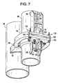
- FIG.7 is a perspective view of FIG. 6 , from a slightly underneath angle.
- Locating bosses 130 may be provided to ensure the proper placement of plates 100/102 relative to brackets 70.
- the locating bosses 130 may include locating boss bolts 132 used to stabilize the bosses 130.
- plates 100/102 may be machined to allow for locating bosses 130 to be an integral part of the plates themselves.
- FIG. 8 is a detailed drawing showing an example embodiment of a restrainer assembly repair 104 including a top bearing plate 100 and a bottom bearing plate 102, the bearing plates 100/102 held together and able to be secured to bracket 70 by mounting bolts 120.
- Optional bolt collars 122 such as an eccentric cam, may be used for fine positioning of the restrainer assembly repair 104 relative to bracket 70 and wedge 60.
- Cut-out areas 65A may be included on the top bearing plate 100, to allow the top plate 100 to fit down over vertical plates 65 (vertical plates 65 are shown in at least FIGS. 6 and 7 ).
- Optional locating bosses 130 may be included to allow the restrainer assembly repair 104 to be more easily positioned relative to the bracket 70.
- Locating boss bolts 132 are used to secure the locating bosses 130 once they are positioned, allowing the restrainer assembly repair 104 to apply a horizontal force to wedge 60.
- plates 100 or 102 may be machined such that locating bosses 130 are an integral part of the plates themselves.
- example embodiments shows two bearing plates (one to be positioned above bracket 70, and the other to be positioned below bracket 70), four mounting bolts 120 (two to be located on either side of a bracket 70), four adjusting bolt collars 122 (designed to contact bracket 70 on the inner and outer surface of the bracket), and two sets of locating bosses 130 and locating boss bolts 132 (designed to contact bracket 70 on the inner surface of the bracket), it should be understood that example embodiments are not limited to this specific design.
- restrainer assembly repair 104 may be provided with just one bearing plate (to be positioned either above or below bracket 70), a greater or lesser number of mounting bolts 120 to be located in any position that securely attaches bearing plates 100/102 to bracket 70, the optional adjusting bolt collars 122 may be provided to interface with either the inner and/or outer surface of bracket 70 (any number of bolt collars 122 may be used; alternatively, no bolt collars 122 may be used), and the optional locating bosses 130 may be provided to interface with either the inner or outer surface of bracket 70 (any number of locating bosses 130 may be used; alternatively, no locating bosses 130 may be used).
- any means may be used to fulfill this purpose.
- clamps, welds, screws, nails, adhesive, or other means may be used to attach plates 100/102 to bracket 70.
- plates 100/102 are referred to as plural (specifically, two plates) throughout this document, it should be understood that, alternatively, only one bearing plate may be used instead.
- example embodiments show mounting bolts 120 that preferably do not penetrate bracket 70, it should be understood that mounting bolts, clamps, screws, nails, or other attachment means may alternatively penetrate bracket 70 as a way of attaching plates 100/102 to bracket 70.
- FIG. 9 is an overhead view of FIGS. 6 and 7 , shown without top bearing plate 100. Notice bolt collars 122 contacting the inner and outer surfaces of bracket 70, while locating bosses 130 are contacting the inner surface of bracket 70.
- FIG. 10 is the same view as shown in FIG. 9 , but with the addition of top bearing plate 100. Notice cut-out area 65A which allows top bearing plate 100 to slide over vertical plates 65.
- FIG. 11 is an example embodiment showing mounting bolts 120 penetrating bracket 70.
- FIG. 11 is an example embodiment showing mounting bolts 120 penetrating bracket 70 using a tighter bolt pattern than FIG. 11 .
Landscapes
- Physics & Mathematics (AREA)
- Engineering & Computer Science (AREA)
- Plasma & Fusion (AREA)
- General Engineering & Computer Science (AREA)
- High Energy & Nuclear Physics (AREA)
- Structures Of Non-Positive Displacement Pumps (AREA)
- Jet Pumps And Other Pumps (AREA)
- Connection Of Plates (AREA)
Description
- Example embodiments relate in general to a method and apparatus for the mechanical repair of a Boiling Water Reactor (BWR) jet pump restrainer assembly. Specifically, example embodiments relate to mechanical repair of a potentially damaged contact area on either an inlet mixer wedge or a restrainer bracket of a restrainer assembly used to horizontally support a jet pump assembly against riser piping to reduce vibration.
- BWRs are designed to generate steam in reactor pressure vessels ("RPVs") by heating the water surrounding uranium-containing tubes of fuel assemblies located in the RPV core regions. The RPVs have recirculation loops designed to facilitate the circulation of water in the core regions. The recirculation loops generally include large centrifugal pumps that pump water out of the RPVs and return the water to the inlets of jet pump assemblies located in annular regions in the RPVs surrounding the core regions. The jet pump assemblies are designed to entrain the surrounding water in the annular regions and then discharge the water in a manner that induces a desired flow pattern in the core regions.
- The jet pump assemblies are subject to vibrations caused by hydraulic forces due to the flow of water and/or by the rotation of the centrifugal pumps. Thus, in one BWR design, the jet pump assemblies are horizontally supported against vibration with a jet pump restrainer assembly including a bracket using a three point suspension system. A three point system generally includes a wedge movably mounted on a vertically oriented guide rod that is attached to a jet pump assembly and extends through the space between the bracket and the jet pump. The wedge, which may weigh about seven pounds, is designed to slide downwardly under the force of gravity into the space between the bracket and the jet pump assembly and thereby urge the jet pump against the adjustment screws.
- It has been found that the mating (or seating) surfaces of the wedges and/or the brackets of some commercial BWRs have worn substantially after operation over long periods of time. In some cases, the softer interior metal underlying the hardened surfaces of the wedges have worn extensively. It is believed that the wearing is caused by a fretting type of action when the hydraulic forces and/or pump vibrations induce the wedges to chatter or to rise upwardly and then fall back against the bracket. In addition, it is believed that the jet pump assemblies may move away from the adjustment screws in extreme cases.
- The jet pump restrainer assemblies may be repaired by replacing the worn wedges and/or brackets. However, the jet pump assemblies and/or brackets would need to be disassembled, machined and reassembled, and the old parts would need to be replaced.
-
US 2004/0190671 A1 discloses a jet pump assembly repair method in which wear between corresponding contact surfaces of a wedge and a bracket is addressed by use of a flanged sleeve which is wrapped around surfaces of the wedge and/or bracket.
Patent documentsUS2006/0189434 andJP 2007-333431 - There is provided herein a jet pump restrainer repair apparatus in accordance with
claims 1 and 5, and a method of jet pump restrainer assembly repair in accordance with claim 8. - Example embodiments provide a method of repairing the BWR jet pump restrainer assemblies without requiring the disassembly of the jet pump assemblies and/or the associated brackets. Example embodiments may also allow for the continued use of the worn wedges and/or brackets.
- Example embodiments include a method of repairing a BWR jet pump restrainer assembly, in situ. The jet pump assembly extends vertically through a hole in a bracket attached to a riser pipe and is supported against horizontal movement by a plurality of screws extending from the bracket toward the jet pump assembly by a wedge extending into the hole. The wedge is moveably mounted on a vertically extending guide rod fastened to the jet pump assembly. The wedge has a vertically extending inner surface designed to contact the jet pump assembly and an outer surface inclined relative to the vertically extending inner surface designed to contact the bracket. The mating surfaces of the wedge and bracket are the surfaces that are susceptible to wear over time. Example embodiments provide for the placement of bearing plates above and/or below the bracket to provide an additional bearing surface or surfaces between the inlet mixer wedge and the bracket. Example embodiments allow for a bearing plate or plates to assist in supplementing, or in essence expanding the existing contact surface between the inlet mixer wedge and the restrainer bracket. Alternatively, example embodiments allow the existing inlet mixer wedge to be repositioned (the wedge may be partially withdrawn), allowing the bearing plate or plates to be shifted toward the wedge such that a new contact surface between the bearing plates and the wedge replaces the contact surface between the wedge and the existing bracket (i.e., following repair, the wedge and bracket no longer directly contacts each other). Additionally, example embodiments allow for a replacement and/or machining of either the wedge or the bracket, or both, in addition to the placement of a bearing plate or plates to provide additional support. Example embodiments also allow for a replacement wedge that is either smaller (i.e., narrower), larger (i.e., wider), or the same size as the original wedge, or a replacement wedge with a smaller or larger angle of inclination as the original wedge, thereby allowing the wedge to contact the bearing plate or plates while not necessarily contacting the bracket directly.
- The above and other features and advantages of example embodiments will become more apparent by describing in detail example embodiments with reference to the attached drawings. The accompanying drawings are intended to depict example embodiments and should not be interpreted to limit the intended scope of the claims. The accompanying drawings are not to be considered as drawn to scale unless explicitly noted.
-
FIG. 1 is schematic representation of a conventional BWR characterized by a reactor pressure vessel ("RPV") having two recirculation loops; -
FIG. 2 is a partial perspective schematic representation of a RPV taken along Line 2-2 ofFIG. 1 , which depicts a cut-away showing a conventional jet pump assembly arrangement; -
FIG. 3 is a partial perspective elevation view of a jet pump assembly horizontally supported by a conventional jet pump restrainer assembly including a bracket, the view taken along Line 3-3 ofFIG. 2 ; -
FIG. 4 is a simplified rendition of an example embodiment showing a side view of a jet pump restrainer assembly repair including bearing plates interfacing with a conventional bracket and mixer wedge, the view taken along Line 4-4 ofFIG. 3 ; -
FIG. 5 is a simplified rendition of another example embodiment showing a side view of a jet pump restrainer assembly repair including bearing plates interfacing with a conventional bracket and mixer wedge, the view taken along Line 4-4 ofFIG. 3 ; -
FIG. 6 is a perspective view of an example embodiment showing a jet pump restrainer assembly repair interfacing with a conventional bracket and mixing wedge, the view from a slight overhead angle; -
FIG. 7 is a perspective view of an example embodiment showing a jet pump restrainer assembly repair interfacing with a conventional bracket and mixing wedge, the view from a slight underneath angle; -
FIG. 8 is a detailed depiction of an example embodiment of a jet pump restrainer assembly repair showing top and bottom bearing plates, mounting bolts, optional locating bosses, and optional adjusting bolt collars; -
FIG. 9 is an overhead view of an example embodiment of a jet pump restrainer assembly repair, shown without a top bearing plate in order to show optional locating bosses and optional adjusting bolt collars; -
FIG. 10 is the overhead view of the example embodiment ofFIG. 9 , shown with a top bearing plate; -
FIG. 11 is a perspective view of an example embodiment showing mounting bolts penetrating the bracket; and -
FIG. 12 is a perspective view of an example embodiment showing mounting bolts penetrating the bracket, with a tighter bolt pattern than the one shown inFIG. 11 . - Detailed example embodiments are disclosed herein. However, specific structural and functional details disclosed herein are merely representative for purposes of describing example embodiments. Example embodiments may, however, be embodied in many alternate forms within the scope of the appended claims and should not be construed as limited to only the embodiments set forth herein.
- Accordingly, while example embodiments are capable of various modifications and alternative forms, embodiments thereof are shown by way of example in the drawings and will herein be described in detail. It should be understood, however, that there is no intent to limit example embodiments to the particular forms disclosed, but to the contrary, example embodiments are to cover all modifications falling within the scope of the appended claims. Like numbers refer to like elements throughout the description of the figures.
- It will be understood that, although the terms first, second, etc. may be used herein to describe various elements, these elements should not be limited by these terms. These terms are only used to distinguish one element from another. For example, a first element could be termed a second element, and, similarly, a second element could be termed a first element, without departing from the scope of example embodiments. As used herein, the term "and/or" includes any and all combinations of one or more of the associated listed items.
- It will be understood that when an element is referred to as being "connected" or "coupled" to another element, it may be directly connected or coupled to the other element or intervening elements may be present. In contrast, when an element is referred to as being "directly connected" or "directly coupled" to another element, there are no intervening elements present. Other words used to describe the relationship between elements should be interpreted in a like fashion (e.g., "between" versus "directly between", "adjacent" versus "directly adjacent", etc.).
- The terminology used herein is for the purpose of describing particular embodiments only and is not intended to be limiting of example embodiments. As used herein, the singular forms "a", "an" and "the" are intended to include the plural forms as well, unless the context clearly indicates otherwise. It will be further understood that the terms "comprises", "comprising,", "includes" and/or "including", when used herein, specify the presence of stated features, integers, steps, operations, elements, and/or components, but do not preclude the presence or addition of one or more other features, integers, steps, operations, elements, components, and/or groups thereof.
- It should also be noted that in some alternative implementations, the functions/acts noted may occur out of the order noted in the figures. For example, two figures shown in succession may in fact be executed substantially concurrently or may sometimes be executed in the reverse order, depending upon the functionality/acts involved.
- Referring to
FIG. 1 , the drawing is a schematic representation illustrating a commercial boiling water nuclear reactor ("BWR") 10 that generates steam in a reactor pressure vessel ("RPV") 12. Commercial BWRs are designed to drive turbines (not shown), which in turn generates electrical power. TheRPV 12 has a main feedwater inlet nozzle 14 for receiving condensate from a condenser (not shown) and a mainsteam outlet nozzle 16 for providing generated steam to a turbine. TheRPV 12 supports acore shroud 18 containing a plurality of fuel assemblies 20 that generate the steam in its core region and a steam separator/dryer assembly 22 located over thecore shroud 18. - The
RPV 12 illustrated byFIG. 1 has two recirculationloops 30 for facilitating the flow of water in its core region. Eachrecirculation loop 30 has a large centrifugal reactor coolant pump ("RCP") 32 connected with a recirculationwater outlet nozzle 33 of theRPV 12 by pump suction piping 34 for pumping water out of theRPV 12 and pump discharge piping 36 for pumping the water back into theRPV 12. The pump discharge piping 36 generally includes aheader 38 and parallel branch piping, which is illustrated by piping 40. Each of thepiping branches 40 is connected by a recirculationwater inlet nozzle 42 to riser piping 44, which extends to a pair ofjet pump assemblies 46 operating in parallel (only one of which is illustrated byFIG. 1 ). - As is best seen in
FIG. 2 , the riser piping 44 terminates at a manifold 48 sometimes referred to as a "ramshead". Eachjet pump assembly 46 of the pair generally includes aninlet 50 adjacent the manifold 48 that is open to an annular region defined by the wall of theRPV 12 and wall of thecore shroud 18 for entraining the surrounding water in the annular region, amixing section 52 and adiffuser section 54 supported on acrossplate 56. A jetpump restrainer assembly 46A is used to horizontally restrainjet pump assembly 46 toriser pipe 44. Thejet pump assembly 46 may have aboss 49 on its periphery surface as shown inFIG. 3 . - As shown in
FIG. 3 , jetpump restrainer assembly 46A includesbracket 70,wedge 60, adjustment screws 80,horizontal plates 64,vertical plates 65, and welds 72, described in detail, herein.Wedge 60 is movably mounted on a vertically extendingguide rod 62 fastened tojet pump assembly 46.Guide rod 62 may have threaded ends engaged withnuts 63 fastened tohorizontal plates 64 extending betweenvertical plates 65 that extend from the mixingsection 52 of thejet pump assembly 46. Thewedge 60 is designed to slide vertically through ahole 68 in abracket 70, which is attached to the riser piping 44 bywelds 72 or other suitable means. As shown byFIG. 3 , the upper end of theguide rod 62 is above thebracket 70 and the lower end of theguide rod 62 is below thebracket 70. Also, thewedge 60 may move downwardly on theguide rod 62 under the force of gravity to a location where an inner surface of thewedge 60 contacts the jet pump assembly 46 (and preferably the boss 49) and anouter surface 76 of thewedge 60 that is inclined contacts anedge 78 of thebracket 70. The weight of thewedge 60 provides a sufficient force urging thejet pump assembly 46 against two (or more) adjustment screws 80 for horizontally supporting thejet pump assembly 46 against hydraulic forces and vibrations. The adjustment screws 80 may be fixed in place by welds (not shown). Preferably, theouter surface 76 of thewedge 60 is inclined relative to theedge surface 78 of thebracket 70. Advantageously, this three point suspension system can accommodate substantial thermal expansion differences. -
FIG. 4 is a simplified rendition of a jetpump restrainer assembly 46A including awedge 60 located between theboss 49 of mixingsection 52 andbracket 70.Area 61 represents a damaged area between the contact surfaces of thewedge 60 and thebracket 70. Damage may occur on the contact surfaces of either thewedge 60, or thebracket 70, or both, due to thermal expansion, fretting, or wear between thewedge 60 andbracket 70, generally. Jet pumprestrainer assembly repair 104 may include atop bearing plate 100, or abottom bearing plate 102, or both, attached tobracket 70. Theplates 100/102 may be fashioned above and/or belowbracket 70, preferably on a horizontal surface of thebracket 70, such thatplates 100/102 may increase the effective contact area betweenbracket 70 andwedge 60. This may be accomplished by using bearingplates 100/102 with a same angle of inclination as the existingwedge 60 andbracket 70, and aligning the contact surface betweenwedge 60 andplates 100/102 and the contact surface betweenwedge 60 andbracket 70, such thatwedge 60 contacts both theplates 100/102 andbracket 70. While a benefit of the embodiment is that it allows a jetpump restrainer assembly 46A to be repaired in situ, without the disassembly or machining of jetpump restrainer assembly 46A, this embodiment may still allow for the disassembly and/or machining of the wedge and/or bracket during the repair. Specifically, thewedge 60 and/orbracket 70 may be machined in place, or jetpump restrainer assembly 46A may be disassembled allowing the machining and/or replacement of either thewedge 60 or thebracket 70 in addition to the fashioning ofplates 100/102 onbracket 70. Additionally, example embodiments may be used as a preventative measure prior to actual wear betweenwedge 60 andbracket 70. -
FIG. 5 is another example embodiment, similar toFIG. 4 . However,FIG. 5 depicts areplacement wedge 60A with a different angle of inclination than thewedge 60 originally in use.Replacement wedge 60A allows anupper bearing plate 110 and/or alower bearing plate 112, also with a different angle of inclinationmatching replacement wedge 60A, to be shifted towardwedge 60A such thatbracket 70 does not contactreplacement wedge 60A (notice area 61 to indicate the difference in the angle of inclination betweenbracket 70 andwedge 60A, shown as a smaller angle of inclination for exemplary purposes). In an alternative embodiment, the existing wedge 60 (shown inFIG. 4 ) may be partially withdrawn frombracket 70 in order to allow room for bearingplates 110/112 to be shifted toward the location ofwedge 60, thereby allowing only the bearingplates 110/112 and notbracket 70 to contact the wedge. In this alternative embodiment, the contact surface of bearingplates 110/112 may provide for a same angle of inclination asbracket 70 andwedge 60, ensuring that contact surfaces betweenplates 110/112 andwedge 60 match. Alternatively, a wedge with a larger angle of inclination may also be used. Whether the existingwedge 60 or anew wedge 60A is to be used,plates 110/112 should be provided with a contact surface angled to allowplates 110/112 to flushly contact the wedge, ideally allowing bothplates 110/112 to flushly mate with the wedge, although example embodiments may allow for just one ofplates 110/112 to flushly mate with the wedge. -
FIG. 6 is a perspective view, similar toFIG. 3 , with therestrainer assembly repair 104 shown interfacing withwedge 60 andbracket 70.Top bearing plate 100 andbottom bearing plate 102 may be held together by mountingbolts 120. The positioning of the mountingbolts 120 may be in any location that ensures that bearingplates 100/102 are securely affixed tobracket 70, to provideplates 100/102 with stable support to place a horizontal force on theouter surface 76 ofwedge 60. Additionally, adjustingbolt collars 122, such as an eccentric cam, may be used in conjunction with mountingbolts 120 to allow for the fine positioning ofplates 100/102 relative tobracket 70. -
FIG.7 is a perspective view ofFIG. 6 , from a slightly underneath angle. Locating bosses 130 (shown inFIGS. 8 and9 ) may be provided to ensure the proper placement ofplates 100/102 relative tobrackets 70. The locating bosses 130 (shown inFIGS. 8 and9 ) may include locatingboss bolts 132 used to stabilize thebosses 130. Alternatively,plates 100/102 may be machined to allow for locatingbosses 130 to be an integral part of the plates themselves. -
FIG. 8 is a detailed drawing showing an example embodiment of arestrainer assembly repair 104 including atop bearing plate 100 and abottom bearing plate 102, the bearingplates 100/102 held together and able to be secured tobracket 70 by mountingbolts 120.Optional bolt collars 122, such as an eccentric cam, may be used for fine positioning of therestrainer assembly repair 104 relative tobracket 70 andwedge 60. Cut-out areas 65A may be included on thetop bearing plate 100, to allow thetop plate 100 to fit down over vertical plates 65 (vertical plates 65 are shown in at leastFIGS. 6 and7 ). Optional locatingbosses 130 may be included to allow therestrainer assembly repair 104 to be more easily positioned relative to thebracket 70. Locatingboss bolts 132 are used to secure the locatingbosses 130 once they are positioned, allowing therestrainer assembly repair 104 to apply a horizontal force to wedge 60. Alternatively,plates bosses 130 are an integral part of the plates themselves. - While example embodiments shows two bearing plates (one to be positioned above
bracket 70, and the other to be positioned below bracket 70), four mounting bolts 120 (two to be located on either side of a bracket 70), four adjusting bolt collars 122 (designed to contactbracket 70 on the inner and outer surface of the bracket), and two sets of locatingbosses 130 and locating boss bolts 132 (designed to contactbracket 70 on the inner surface of the bracket), it should be understood that example embodiments are not limited to this specific design. Specifically,restrainer assembly repair 104 may be provided with just one bearing plate (to be positioned either above or below bracket 70), a greater or lesser number of mountingbolts 120 to be located in any position that securely attaches bearingplates 100/102 tobracket 70, the optionaladjusting bolt collars 122 may be provided to interface with either the inner and/or outer surface of bracket 70 (any number ofbolt collars 122 may be used; alternatively, nobolt collars 122 may be used), and the optional locatingbosses 130 may be provided to interface with either the inner or outer surface of bracket 70 (any number of locatingbosses 130 may be used; alternatively, no locatingbosses 130 may be used). - Additionally, while example embodiment
use mounting bolts 120 to holdplates 100/102 together and affix therestrainer bracket repair 104 tobracket 70, any means may be used to fulfill this purpose. Specifically, clamps, welds, screws, nails, adhesive, or other means may be used to attachplates 100/102 tobracket 70. Whileplates 100/102 are referred to as plural (specifically, two plates) throughout this document, it should be understood that, alternatively, only one bearing plate may be used instead. Furthermore, while example embodiments show mountingbolts 120 that preferably do not penetratebracket 70, it should be understood that mounting bolts, clamps, screws, nails, or other attachment means may alternatively penetratebracket 70 as a way of attachingplates 100/102 tobracket 70. -
FIG. 9 is an overhead view ofFIGS. 6 and7 , shown withouttop bearing plate 100.Notice bolt collars 122 contacting the inner and outer surfaces ofbracket 70, while locatingbosses 130 are contacting the inner surface ofbracket 70. -
FIG. 10 is the same view as shown inFIG. 9 , but with the addition oftop bearing plate 100. Notice cut-outarea 65A which allowstop bearing plate 100 to slide oververtical plates 65. -
FIG. 11 is an example embodiment showing mountingbolts 120 penetratingbracket 70. -
FIG. 11 is an example embodiment showing mountingbolts 120 penetratingbracket 70 using a tighter bolt pattern thanFIG. 11 . - Example embodiments having thus been described, it will be obvious that the same may be varied in many ways within the scope of the appended claims.
Claims (14)
- A jet pump restrainer assembly repair (104) apparatus comprising:a bearing plate (100/102/110/112) adapted to attached to a horizontal surface of a jet pump restrainer assembly bracket (70), the bearing plate (100/102/110/112) including a contact surface configured to flushly contact a vertically extending inclined contact surface of a mixer wedge (60160A).
- The jet pump restrainer assembly repair apparatus of claim 1,the bearing plate contact surface having an angle of inclination matching an angle of inclination of a contact surface between the mixer wedge and the jet pump restrainer assembly bracket.
- The jet pump restrainer assembly repair apparatus of claim 1, wherein the bearing plate contact surface has an angle of inclination that is different than an angle of inclination of a contact surface between the mixer wedge and the jet pump restrainer assembly bracket.
- The jet pump restrainer assembly repair apparatus of claim 2, wherein the bearing plate is adapted to be attached to the jet pump restrainer assembly bracket such that the contact surface between the mixer wedge and the bearing plate and the contact surface between the mixer wedge and the jet pump restrainer assembly bracket align, allowing the mixer wedge to contact both the bearing plate and the jet pump restrainer assembly bracket.
- A jet pump restrainer assembly repair apparatus (104) comprising:a top bearing plate (100/110) adapted to be attached to an upper horizontal surface of a jet pump restrainer assembly bracket (70);a bottom bearing plate (102/112) adapted to be attached to a lower horizontal surface of the jet pump restrainer assembly bracket, the top and bottom bearing plates having contact surfaces angled to mate flushly with a vertically extending inclined contact surface of a mixer wedge (60/60A); anda plurality of mounting bolts (120) adapted to hold the top and bottom bearing plates together and secure the top and bottom bearing plates to the jet pump restrainer assembly bracket.
- The jet pump restrainer assembly repair apparatus of claim 5, further comprising:a locating boss (130) on the top or bottom bearing plate, the locating boss positioned on the top or bottom bearing plate to ensure that the jet pump restrainer assembly repair is properly aligned with the jet pump restrainer assembly bracket; anda locating boss bolt (132) securing the locating boss on the top or bottom bearing plate.
- The jet pump restrainer assembly repair apparatus of claim 5 or 6, further comprising:an adjusting bolt collar (122) adapted to be attached to the jet pump restrainer assembly repair apparatus to allow fine positioning of the jet pump restrainer assembly repair apparatus relative to the jet pump restrainer assembly bracket.
- A method of jet pump restrainer assembly repair (104) comprising:attaching a bearing plate (100/102/110/112) to a horizontal surface of a jet pump restrainer assembly bracket (70), the bearing plate including a contact surface configured to flushly contact a vertically extending inclined contact surface of a mixer wedge (60/60A).
- The method of jet pump restrainer assembly repair of claim 8, further comprising:aligning a locating boss (130) with a surface of the jet pump restrainer assembly bracket allowing the jet pump restrainer assembly repair to be properly positioned on the jet pump restrainer assembly bracket, the locating boss attached to the bearing plate.
- The method of jet pump restrainer assembly repair of claim 8 or 9, further comprising:using an adjusting bolt collar (122) to establish fine positioning of the jet pump restrainer assembly repair relative to the jet pump restrainer assembly bracket, the adjusting bolt collar being attached to the jet pump restrainer assembly repair.
- The method of jet pump restrainer assembly repair of any of claims 8 to 10, further comprising:matching an angle of inclination of the contact surface between the mixer wedge and the bearing plate and an angle of inclination of a contact surface between the mixer wedge and the jet pump restrainer assembly bracket.
- The method of jet pump restrainer assembly repair of claim 11, further comprising:aligning the contact surface between the mixer wedge and the bearing plate and the contact surface between the mixer wedge and the jet pump restrainer assembly bracket, allowing the mixer wedge to contact both the bearing plate and the jet pump restrainer assembly bracket.
- The method of jet pump restrainer assembly repair of any of claims 8 to 10, further comprising:forming an angle of inclination of the contact surface of the bearing plate that is different than an angle of inclination of a contact surface between the mixer wedge and the jet pump restrainer assembly bracket.
- The method of jet pump restrainer assembly repair of any of claims 8 to 11 and 13, further comprising:shifting the location of the bearing plate on the jet pump restrainer assembly bracket toward the mixer wedge, allowing only the bearing plate and not the jet pump restrainer assembly bracket to contact the mixer wedge.shifting the location of the bearing plate on the jet pump restrainer assembly bracket toward the mixer wedge, allowing only the bearing plate and not the jet pump restrainer assembly bracket to contact the mixer wedge.
Applications Claiming Priority (1)
| Application Number | Priority Date | Filing Date | Title |
|---|---|---|---|
| US12/385,041 US8819911B2 (en) | 2009-03-30 | 2009-03-30 | Method and apparatus for jet pump restrainer assembly repair |
Publications (3)
| Publication Number | Publication Date |
|---|---|
| EP2237284A2 EP2237284A2 (en) | 2010-10-06 |
| EP2237284A3 EP2237284A3 (en) | 2013-11-27 |
| EP2237284B1 true EP2237284B1 (en) | 2014-11-05 |
Family
ID=42263145
Family Applications (1)
| Application Number | Title | Priority Date | Filing Date |
|---|---|---|---|
| EP10156868.1A Active EP2237284B1 (en) | 2009-03-30 | 2010-03-18 | Method and apparatus for repairing a jet pump restrainer assembly |
Country Status (6)
| Country | Link |
|---|---|
| US (1) | US8819911B2 (en) |
| EP (1) | EP2237284B1 (en) |
| JP (1) | JP5744411B2 (en) |
| ES (1) | ES2526298T3 (en) |
| MX (1) | MX2010003454A (en) |
| TW (1) | TWI474337B (en) |
Families Citing this family (13)
| Publication number | Priority date | Publication date | Assignee | Title |
|---|---|---|---|---|
| US8422618B2 (en) | 2009-12-08 | 2013-04-16 | Ge-Hitachi Nuclear Energy Americas Llc | Apparatus and system for restricting the movement of a component |
| US8731127B2 (en) * | 2010-08-04 | 2014-05-20 | Ge-Hitachi Nuclear Energy Americas, Llc | Method and apparatus for a BWR inlet mixer clamp assembly |
| US8731134B2 (en) * | 2010-08-06 | 2014-05-20 | Ge-Hitachi Nuclear Energy Americas Llc | Method and apparatus for a BWR jet pump inlet mixer support |
| US8792608B2 (en) * | 2010-11-05 | 2014-07-29 | Ge-Hitachi Nuclear Energy Americas Llc | BWR jet pump inlet-mixer main wedge with inserts |
| US8983018B2 (en) * | 2010-12-16 | 2015-03-17 | Ge-Hitachi Nuclear Energy Americas Llc | Method and apparatus for a riser pipe repair with compression |
| US9589684B2 (en) | 2012-05-16 | 2017-03-07 | Ge-Hitachi Nuclear Energy Americas Llc | Apparatuses and methods for controlling movement of components |
| US20140079468A1 (en) * | 2012-09-20 | 2014-03-20 | Areva Np Inc. | Jet Pump Stabilizer |
| US9659676B2 (en) * | 2012-10-18 | 2017-05-23 | Westinghouse Electric Company Llc | Jet pump diffuser stack repair |
| TWI578333B (en) * | 2014-09-25 | 2017-04-11 | 東芝股份有限公司 | Boiling water type nuclear reactor and jet boiling nuclear reactor |
| US10436227B2 (en) * | 2015-10-16 | 2019-10-08 | Framatome Inc. | Sealing device for jet pump slip joints |
| US12183472B2 (en) * | 2018-06-18 | 2024-12-31 | Ge-Hitachi Nuclear Energy Americas Llc | Systems and methods for steam separator tie bar repair or replacement |
| CN113909715A (en) * | 2021-11-19 | 2022-01-11 | 大连工业大学 | Reprocessing clamping device for laser material-increasing lug of aviation jet pump |
| WO2024112974A1 (en) | 2022-11-25 | 2024-05-30 | Ge-Hitachi Nuclear Energy Americas Llc | Jet pump clamps and methods for use in a nuclear reactor jet pump |
Family Cites Families (11)
| Publication number | Priority date | Publication date | Assignee | Title |
|---|---|---|---|---|
| US4675149A (en) * | 1986-01-31 | 1987-06-23 | General Electric Company | Jet pump beam holder/positioner tool |
| US6320923B2 (en) * | 1997-10-28 | 2001-11-20 | Westinghouse Electric Company Llc | BWR jet pump wedge keeper |
| US6052425A (en) * | 1998-12-21 | 2000-04-18 | General Electric Company | Jet pump auxiliary wedge |
| US5978433A (en) * | 1998-12-21 | 1999-11-02 | General Electric Company | Jet pump wedge locking support apparatus |
| US6435839B1 (en) * | 2001-11-19 | 2002-08-20 | General Electric Company | Jet pump sensing line clamp assembly and methods |
| JP4097935B2 (en) | 2001-11-26 | 2008-06-11 | 株式会社東芝 | Jet pump intermediate support device |
| US6865243B2 (en) * | 2002-10-25 | 2005-03-08 | General Electric Company | Method of detecting cracks in jet pump beams of a nuclear reactor |
| US20040190671A1 (en) * | 2003-03-26 | 2004-09-30 | Wivagg Adrian P. | Jet pump assembly repair method |
| US7272204B2 (en) * | 2004-08-31 | 2007-09-18 | General Electric Company | Method and apparatus for clamping a riser brace assembly in nuclear reactor |
| JP2007333431A (en) | 2006-06-12 | 2007-12-27 | Hitachi Ltd | Jet pump measuring piping clamping device |
| US8422618B2 (en) * | 2009-12-08 | 2013-04-16 | Ge-Hitachi Nuclear Energy Americas Llc | Apparatus and system for restricting the movement of a component |
-
2009
- 2009-03-30 US US12/385,041 patent/US8819911B2/en not_active Expired - Fee Related
-
2010
- 2010-03-18 TW TW99108031A patent/TWI474337B/en active
- 2010-03-18 ES ES10156868.1T patent/ES2526298T3/en active Active
- 2010-03-18 EP EP10156868.1A patent/EP2237284B1/en active Active
- 2010-03-26 MX MX2010003454A patent/MX2010003454A/en active IP Right Grant
- 2010-03-26 JP JP2010071277A patent/JP5744411B2/en active Active
Also Published As
| Publication number | Publication date |
|---|---|
| JP5744411B2 (en) | 2015-07-08 |
| MX2010003454A (en) | 2010-09-29 |
| US8819911B2 (en) | 2014-09-02 |
| TW201040987A (en) | 2010-11-16 |
| EP2237284A3 (en) | 2013-11-27 |
| JP2010237207A (en) | 2010-10-21 |
| US20100242279A1 (en) | 2010-09-30 |
| TWI474337B (en) | 2015-02-21 |
| EP2237284A2 (en) | 2010-10-06 |
| ES2526298T3 (en) | 2015-01-09 |
Similar Documents
| Publication | Publication Date | Title |
|---|---|---|
| US8819911B2 (en) | Method and apparatus for jet pump restrainer assembly repair | |
| EP2236883B1 (en) | Apparatus and system for dampening the vibration experienced by a sprager pipe | |
| JP5685394B2 (en) | Riser brace clamp for jet pump | |
| EP2333782B1 (en) | System for restricting the movement of a component | |
| JPH08313676A (en) | Method and apparatus for lateral restraint of core plate of boiling water reactor | |
| US7023949B2 (en) | Jet pump assembly repair method | |
| US8170174B1 (en) | Simplified jet pump riser brace clamp | |
| EP0962941B1 (en) | Nuclear reactor core spray line coupling apparatus and methods | |
| US8605852B2 (en) | Wedge positioning apparatus for jet pump assemblies in nuclear reactors | |
| EP2909839B1 (en) | Jet pump diffuser stack repair | |
| US20040052325A1 (en) | Jet pump set screw wedge | |
| US20120018612A1 (en) | Method and apparatus for a bwr jet pump main wedge clamp | |
| US8731127B2 (en) | Method and apparatus for a BWR inlet mixer clamp assembly | |
| US20090294229A1 (en) | System for dampening the vibration experienced by a line | |
| US7596200B2 (en) | Method and apparatus for repairing a jet pump riser brace to reactor vessel pad attachment in a nuclear reactor | |
| US8328239B2 (en) | Mechanical assembly for securing the structural integrity of a pipe joint | |
| JP5281745B2 (en) | Apparatus for stabilizing a steam dryer assembly in a reactor pressure vessel |
Legal Events
| Date | Code | Title | Description |
|---|---|---|---|
| PUAI | Public reference made under article 153(3) epc to a published international application that has entered the european phase |
Free format text: ORIGINAL CODE: 0009012 |
|
| AK | Designated contracting states |
Kind code of ref document: A2 Designated state(s): AT BE BG CH CY CZ DE DK EE ES FI FR GB GR HR HU IE IS IT LI LT LU LV MC MK MT NL NO PL PT RO SE SI SK SM TR |
|
| PUAL | Search report despatched |
Free format text: ORIGINAL CODE: 0009013 |
|
| AK | Designated contracting states |
Kind code of ref document: A3 Designated state(s): AT BE BG CH CY CZ DE DK EE ES FI FR GB GR HR HU IE IS IT LI LT LU LV MC MK MT NL NO PL PT RO SE SI SK SM TR |
|
| RIC1 | Information provided on ipc code assigned before grant |
Ipc: G21C 15/25 20060101AFI20131018BHEP Ipc: G21C 19/20 20060101ALI20131018BHEP |
|
| 17P | Request for examination filed |
Effective date: 20140527 |
|
| RBV | Designated contracting states (corrected) |
Designated state(s): AT BE BG CH CY CZ DE DK EE ES FI FR GB GR HR HU IE IS IT LI LT LU LV MC MK MT NL NO PL PT RO SE SI SK SM TR |
|
| GRAP | Despatch of communication of intention to grant a patent |
Free format text: ORIGINAL CODE: EPIDOSNIGR1 |
|
| INTG | Intention to grant announced |
Effective date: 20140718 |
|
| GRAS | Grant fee paid |
Free format text: ORIGINAL CODE: EPIDOSNIGR3 |
|
| GRAA | (expected) grant |
Free format text: ORIGINAL CODE: 0009210 |
|
| AK | Designated contracting states |
Kind code of ref document: B1 Designated state(s): AT BE BG CH CY CZ DE DK EE ES FI FR GB GR HR HU IE IS IT LI LT LU LV MC MK MT NL NO PL PT RO SE SI SK SM TR |
|
| REG | Reference to a national code |
Ref country code: GB Ref legal event code: FG4D |
|
| REG | Reference to a national code |
Ref country code: CH Ref legal event code: EP |
|
| REG | Reference to a national code |
Ref country code: AT Ref legal event code: REF Ref document number: 694981 Country of ref document: AT Kind code of ref document: T Effective date: 20141115 |
|
| REG | Reference to a national code |
Ref country code: IE Ref legal event code: FG4D |
|
| REG | Reference to a national code |
Ref country code: DE Ref legal event code: R096 Ref document number: 602010019906 Country of ref document: DE Effective date: 20141218 |
|
| REG | Reference to a national code |
Ref country code: ES Ref legal event code: FG2A Ref document number: 2526298 Country of ref document: ES Kind code of ref document: T3 Effective date: 20150109 |
|
| REG | Reference to a national code |
Ref country code: SE Ref legal event code: TRGR |
|
| REG | Reference to a national code |
Ref country code: AT Ref legal event code: MK05 Ref document number: 694981 Country of ref document: AT Kind code of ref document: T Effective date: 20141105 |
|
| REG | Reference to a national code |
Ref country code: NL Ref legal event code: VDEP Effective date: 20141105 |
|
| REG | Reference to a national code |
Ref country code: LT Ref legal event code: MG4D |
|
| PG25 | Lapsed in a contracting state [announced via postgrant information from national office to epo] |
Ref country code: NL Free format text: LAPSE BECAUSE OF FAILURE TO SUBMIT A TRANSLATION OF THE DESCRIPTION OR TO PAY THE FEE WITHIN THE PRESCRIBED TIME-LIMIT Effective date: 20141105 Ref country code: IS Free format text: LAPSE BECAUSE OF FAILURE TO SUBMIT A TRANSLATION OF THE DESCRIPTION OR TO PAY THE FEE WITHIN THE PRESCRIBED TIME-LIMIT Effective date: 20150305 Ref country code: NO Free format text: LAPSE BECAUSE OF FAILURE TO SUBMIT A TRANSLATION OF THE DESCRIPTION OR TO PAY THE FEE WITHIN THE PRESCRIBED TIME-LIMIT Effective date: 20150205 Ref country code: PT Free format text: LAPSE BECAUSE OF FAILURE TO SUBMIT A TRANSLATION OF THE DESCRIPTION OR TO PAY THE FEE WITHIN THE PRESCRIBED TIME-LIMIT Effective date: 20150305 Ref country code: LT Free format text: LAPSE BECAUSE OF FAILURE TO SUBMIT A TRANSLATION OF THE DESCRIPTION OR TO PAY THE FEE WITHIN THE PRESCRIBED TIME-LIMIT Effective date: 20141105 |
|
| PG25 | Lapsed in a contracting state [announced via postgrant information from national office to epo] |
Ref country code: GR Free format text: LAPSE BECAUSE OF FAILURE TO SUBMIT A TRANSLATION OF THE DESCRIPTION OR TO PAY THE FEE WITHIN THE PRESCRIBED TIME-LIMIT Effective date: 20150206 Ref country code: AT Free format text: LAPSE BECAUSE OF FAILURE TO SUBMIT A TRANSLATION OF THE DESCRIPTION OR TO PAY THE FEE WITHIN THE PRESCRIBED TIME-LIMIT Effective date: 20141105 Ref country code: PL Free format text: LAPSE BECAUSE OF FAILURE TO SUBMIT A TRANSLATION OF THE DESCRIPTION OR TO PAY THE FEE WITHIN THE PRESCRIBED TIME-LIMIT Effective date: 20141105 Ref country code: CY Free format text: LAPSE BECAUSE OF FAILURE TO SUBMIT A TRANSLATION OF THE DESCRIPTION OR TO PAY THE FEE WITHIN THE PRESCRIBED TIME-LIMIT Effective date: 20141105 Ref country code: HR Free format text: LAPSE BECAUSE OF FAILURE TO SUBMIT A TRANSLATION OF THE DESCRIPTION OR TO PAY THE FEE WITHIN THE PRESCRIBED TIME-LIMIT Effective date: 20141105 Ref country code: LV Free format text: LAPSE BECAUSE OF FAILURE TO SUBMIT A TRANSLATION OF THE DESCRIPTION OR TO PAY THE FEE WITHIN THE PRESCRIBED TIME-LIMIT Effective date: 20141105 |
|
| PG25 | Lapsed in a contracting state [announced via postgrant information from national office to epo] |
Ref country code: SK Free format text: LAPSE BECAUSE OF FAILURE TO SUBMIT A TRANSLATION OF THE DESCRIPTION OR TO PAY THE FEE WITHIN THE PRESCRIBED TIME-LIMIT Effective date: 20141105 Ref country code: RO Free format text: LAPSE BECAUSE OF FAILURE TO SUBMIT A TRANSLATION OF THE DESCRIPTION OR TO PAY THE FEE WITHIN THE PRESCRIBED TIME-LIMIT Effective date: 20141105 Ref country code: EE Free format text: LAPSE BECAUSE OF FAILURE TO SUBMIT A TRANSLATION OF THE DESCRIPTION OR TO PAY THE FEE WITHIN THE PRESCRIBED TIME-LIMIT Effective date: 20141105 Ref country code: DK Free format text: LAPSE BECAUSE OF FAILURE TO SUBMIT A TRANSLATION OF THE DESCRIPTION OR TO PAY THE FEE WITHIN THE PRESCRIBED TIME-LIMIT Effective date: 20141105 Ref country code: CZ Free format text: LAPSE BECAUSE OF FAILURE TO SUBMIT A TRANSLATION OF THE DESCRIPTION OR TO PAY THE FEE WITHIN THE PRESCRIBED TIME-LIMIT Effective date: 20141105 |
|
| REG | Reference to a national code |
Ref country code: DE Ref legal event code: R097 Ref document number: 602010019906 Country of ref document: DE |
|
| PLBE | No opposition filed within time limit |
Free format text: ORIGINAL CODE: 0009261 |
|
| STAA | Information on the status of an ep patent application or granted ep patent |
Free format text: STATUS: NO OPPOSITION FILED WITHIN TIME LIMIT |
|
| 26N | No opposition filed |
Effective date: 20150806 |
|
| PG25 | Lapsed in a contracting state [announced via postgrant information from national office to epo] |
Ref country code: MC Free format text: LAPSE BECAUSE OF FAILURE TO SUBMIT A TRANSLATION OF THE DESCRIPTION OR TO PAY THE FEE WITHIN THE PRESCRIBED TIME-LIMIT Effective date: 20141105 Ref country code: LU Free format text: LAPSE BECAUSE OF FAILURE TO SUBMIT A TRANSLATION OF THE DESCRIPTION OR TO PAY THE FEE WITHIN THE PRESCRIBED TIME-LIMIT Effective date: 20150318 |
|
| GBPC | Gb: european patent ceased through non-payment of renewal fee |
Effective date: 20150318 |
|
| PG25 | Lapsed in a contracting state [announced via postgrant information from national office to epo] |
Ref country code: IT Free format text: LAPSE BECAUSE OF FAILURE TO SUBMIT A TRANSLATION OF THE DESCRIPTION OR TO PAY THE FEE WITHIN THE PRESCRIBED TIME-LIMIT Effective date: 20141105 |
|
| REG | Reference to a national code |
Ref country code: FR Ref legal event code: ST Effective date: 20151130 |
|
| REG | Reference to a national code |
Ref country code: IE Ref legal event code: MM4A |
|
| PG25 | Lapsed in a contracting state [announced via postgrant information from national office to epo] |
Ref country code: GB Free format text: LAPSE BECAUSE OF NON-PAYMENT OF DUE FEES Effective date: 20150318 Ref country code: IE Free format text: LAPSE BECAUSE OF NON-PAYMENT OF DUE FEES Effective date: 20150318 |
|
| PG25 | Lapsed in a contracting state [announced via postgrant information from national office to epo] |
Ref country code: SI Free format text: LAPSE BECAUSE OF FAILURE TO SUBMIT A TRANSLATION OF THE DESCRIPTION OR TO PAY THE FEE WITHIN THE PRESCRIBED TIME-LIMIT Effective date: 20141105 Ref country code: FR Free format text: LAPSE BECAUSE OF NON-PAYMENT OF DUE FEES Effective date: 20150331 |
|
| PG25 | Lapsed in a contracting state [announced via postgrant information from national office to epo] |
Ref country code: MT Free format text: LAPSE BECAUSE OF FAILURE TO SUBMIT A TRANSLATION OF THE DESCRIPTION OR TO PAY THE FEE WITHIN THE PRESCRIBED TIME-LIMIT Effective date: 20141105 |
|
| PG25 | Lapsed in a contracting state [announced via postgrant information from national office to epo] |
Ref country code: BG Free format text: LAPSE BECAUSE OF FAILURE TO SUBMIT A TRANSLATION OF THE DESCRIPTION OR TO PAY THE FEE WITHIN THE PRESCRIBED TIME-LIMIT Effective date: 20141105 Ref country code: SM Free format text: LAPSE BECAUSE OF FAILURE TO SUBMIT A TRANSLATION OF THE DESCRIPTION OR TO PAY THE FEE WITHIN THE PRESCRIBED TIME-LIMIT Effective date: 20141105 Ref country code: HU Free format text: LAPSE BECAUSE OF FAILURE TO SUBMIT A TRANSLATION OF THE DESCRIPTION OR TO PAY THE FEE WITHIN THE PRESCRIBED TIME-LIMIT; INVALID AB INITIO Effective date: 20100318 |
|
| PG25 | Lapsed in a contracting state [announced via postgrant information from national office to epo] |
Ref country code: TR Free format text: LAPSE BECAUSE OF FAILURE TO SUBMIT A TRANSLATION OF THE DESCRIPTION OR TO PAY THE FEE WITHIN THE PRESCRIBED TIME-LIMIT Effective date: 20141105 |
|
| PG25 | Lapsed in a contracting state [announced via postgrant information from national office to epo] |
Ref country code: BE Free format text: LAPSE BECAUSE OF FAILURE TO SUBMIT A TRANSLATION OF THE DESCRIPTION OR TO PAY THE FEE WITHIN THE PRESCRIBED TIME-LIMIT Effective date: 20141105 |
|
| PG25 | Lapsed in a contracting state [announced via postgrant information from national office to epo] |
Ref country code: MK Free format text: LAPSE BECAUSE OF FAILURE TO SUBMIT A TRANSLATION OF THE DESCRIPTION OR TO PAY THE FEE WITHIN THE PRESCRIBED TIME-LIMIT Effective date: 20141105 |
|
| PGFP | Annual fee paid to national office [announced via postgrant information from national office to epo] |
Ref country code: DE Payment date: 20220217 Year of fee payment: 13 |
|
| PGFP | Annual fee paid to national office [announced via postgrant information from national office to epo] |
Ref country code: SE Payment date: 20220217 Year of fee payment: 13 |
|
| REG | Reference to a national code |
Ref country code: DE Ref legal event code: R119 Ref document number: 602010019906 Country of ref document: DE |
|
| REG | Reference to a national code |
Ref country code: SE Ref legal event code: EUG |
|
| PG25 | Lapsed in a contracting state [announced via postgrant information from national office to epo] |
Ref country code: SE Free format text: LAPSE BECAUSE OF NON-PAYMENT OF DUE FEES Effective date: 20230319 Ref country code: DE Free format text: LAPSE BECAUSE OF NON-PAYMENT OF DUE FEES Effective date: 20231003 |
|
| PGFP | Annual fee paid to national office [announced via postgrant information from national office to epo] |
Ref country code: ES Payment date: 20250401 Year of fee payment: 16 |
|
| PGFP | Annual fee paid to national office [announced via postgrant information from national office to epo] |
Ref country code: CH Payment date: 20250401 Year of fee payment: 16 |
|
| REG | Reference to a national code |
Ref country code: CH Ref legal event code: U11 Free format text: ST27 STATUS EVENT CODE: U-0-0-U10-U11 (AS PROVIDED BY THE NATIONAL OFFICE) Effective date: 20260401 |
|
| PGFP | Annual fee paid to national office [announced via postgrant information from national office to epo] |
Ref country code: FI Payment date: 20260219 Year of fee payment: 17 |