EP2237270A1 - A method for determining a noise reference signal for noise compensation and/or noise reduction - Google Patents
A method for determining a noise reference signal for noise compensation and/or noise reduction Download PDFInfo
- Publication number
- EP2237270A1 EP2237270A1 EP09004609A EP09004609A EP2237270A1 EP 2237270 A1 EP2237270 A1 EP 2237270A1 EP 09004609 A EP09004609 A EP 09004609A EP 09004609 A EP09004609 A EP 09004609A EP 2237270 A1 EP2237270 A1 EP 2237270A1
- Authority
- EP
- European Patent Office
- Prior art keywords
- signal
- noise
- audio signal
- adaptive filtering
- filtering means
- Prior art date
- Legal status (The legal status is an assumption and is not a legal conclusion. Google has not performed a legal analysis and makes no representation as to the accuracy of the status listed.)
- Granted
Links
Images


Classifications
-
- G—PHYSICS
- G10—MUSICAL INSTRUMENTS; ACOUSTICS
- G10K—SOUND-PRODUCING DEVICES; METHODS OR DEVICES FOR PROTECTING AGAINST, OR FOR DAMPING, NOISE OR OTHER ACOUSTIC WAVES IN GENERAL; ACOUSTICS NOT OTHERWISE PROVIDED FOR
- G10K11/00—Methods or devices for transmitting, conducting or directing sound in general; Methods or devices for protecting against, or for damping, noise or other acoustic waves in general
- G10K11/002—Devices for damping, suppressing, obstructing or conducting sound in acoustic devices
-
- G—PHYSICS
- G10—MUSICAL INSTRUMENTS; ACOUSTICS
- G10L—SPEECH ANALYSIS OR SYNTHESIS; SPEECH RECOGNITION; SPEECH OR VOICE PROCESSING; SPEECH OR AUDIO CODING OR DECODING
- G10L21/00—Processing of the speech or voice signal to produce another audible or non-audible signal, e.g. visual or tactile, in order to modify its quality or its intelligibility
- G10L21/02—Speech enhancement, e.g. noise reduction or echo cancellation
- G10L21/0208—Noise filtering
- G10L21/0216—Noise filtering characterised by the method used for estimating noise
- G10L2021/02161—Number of inputs available containing the signal or the noise to be suppressed
- G10L2021/02165—Two microphones, one receiving mainly the noise signal and the other one mainly the speech signal
-
- G—PHYSICS
- G10—MUSICAL INSTRUMENTS; ACOUSTICS
- G10L—SPEECH ANALYSIS OR SYNTHESIS; SPEECH RECOGNITION; SPEECH OR VOICE PROCESSING; SPEECH OR AUDIO CODING OR DECODING
- G10L21/00—Processing of the speech or voice signal to produce another audible or non-audible signal, e.g. visual or tactile, in order to modify its quality or its intelligibility
- G10L21/02—Speech enhancement, e.g. noise reduction or echo cancellation
- G10L21/0208—Noise filtering
- G10L21/0216—Noise filtering characterised by the method used for estimating noise
- G10L2021/02161—Number of inputs available containing the signal or the noise to be suppressed
- G10L2021/02166—Microphone arrays; Beamforming
-
- H—ELECTRICITY
- H04—ELECTRIC COMMUNICATION TECHNIQUE
- H04R—LOUDSPEAKERS, MICROPHONES, GRAMOPHONE PICK-UPS OR LIKE ACOUSTIC ELECTROMECHANICAL TRANSDUCERS; DEAF-AID SETS; PUBLIC ADDRESS SYSTEMS
- H04R2499/00—Aspects covered by H04R or H04S not otherwise provided for in their subgroups
- H04R2499/10—General applications
- H04R2499/13—Acoustic transducers and sound field adaptation in vehicles
-
- H—ELECTRICITY
- H04—ELECTRIC COMMUNICATION TECHNIQUE
- H04R—LOUDSPEAKERS, MICROPHONES, GRAMOPHONE PICK-UPS OR LIKE ACOUSTIC ELECTROMECHANICAL TRANSDUCERS; DEAF-AID SETS; PUBLIC ADDRESS SYSTEMS
- H04R3/00—Circuits for transducers, loudspeakers or microphones
- H04R3/005—Circuits for transducers, loudspeakers or microphones for combining the signals of two or more microphones
Definitions
- the present invention relates to a method for determining a noise reference signal for noise compensation and/or noise reduction.
- Noise compensation and/or noise reduction in acoustic signals is an important issue, for example, in the field of speech signal processing.
- the quality of an audio signal e.g. of a speech signal
- Hands-free telephony systems or speech recognition systems may be used in a noisy environment such as in a vehicular cabin.
- the voice signal may be interfered by background noise such as noise of the engine or noise of the rolling tires.
- Noise compensation methods may be used to compensate for the background noise thereby improving the signal quality and reducing misrecognitions.
- noise compensation and/or noise reduction usually involve multi-channel systems.
- two-channel systems are used, wherein a first channel comprises a disturbed audio signal and a second channel comprises a noise reference signal.
- FIG. 6 shows an example of such a system.
- Two microphones 605 are configured to detect a wanted signal of a wanted sound source, for example, a speech signal.
- a first microphone signal is output by a first microphone on a first signal path and a second microphone signal is output by a second microphone on a second signal path.
- the first and the second microphone signal comprise a noise component 603 and 604, respectively, originating from one or more noise sources and a wanted signal component originating from the wanted sound source.
- the transfer between the wanted signal and the first and the second microphone signal may be modeled by a first and a second transfer function 601 and 602, respectively.
- the second microphone signal is filtered by an interference canceller 609, which comprises an adaptive filtering means and determines an estimate for the noise component in the first microphone signal based on the second microphone signal.
- the output of the interference canceller 609 is subtracted from the first microphone signal by a combining means 610, thereby obtaining an output signal with reduced noise.
- the quality of the output signal depends on the wanted signal component in the second microphone signal.
- the second microphone signal and hence the output of the interference canceller 609 do not comprise a wanted signal component.
- the quality of noise compensation in the output signal with reduced noise also depends on the correlation between the noise components 603 and 604.
- a low correlation implies that the estimate of the interference canceller 609 is a bad estimate for the noise component of the first microphone signal and that therefore the quality of the output signal with reduced noise is low.
- the two microphones 605 should have a small relative distance from each other. As a consequence, however, the second microphone signal will also comprise a significant wanted signal component.
- Figure 7 shows such a system comprising two microphones 705, an interference canceller 709 and a first combining means 710 configured to subtract the estimate of the noise component from a first microphone signal.
- the first microphone signal from a first signal path may be used as input for an adaptive filtering means 715.
- the output of the adaptive filtering means 715 may be combined with a second microphone signal using a second combining means 716, thereby obtaining a noise reference signal on a second signal path.
- This noise reference signal may be used as an input for the interference canceller 709 and the output of the interference canceller 709 may be subtracted from the first microphone signal using combining means 710 to obtain an output signal with reduced noise.
- the first and the second microphone signal may comprise a noise component 703 and 704, respectively.
- a first transfer function 701 modeling the transfer between a wanted signal and the first microphone signal on the first signal path may be denoted by G 1 (e j ⁇ ) and a second transfer function 702 modeling the transfer between the wanted signal and the second microphone signal on the second signal path may be denoted by G 2 (e j ⁇ ).
- G 1 (e j ⁇ ) a first transfer function 701 modeling the transfer between a wanted signal and the first microphone signal on the first signal path
- G 2 (e j ⁇ ) modeling the transfer between the wanted signal and the second microphone signal on the second signal path
- G 2 (e j ⁇ ) a transfer function 702 modeling the transfer between the wanted signal and the second microphone signal on the second signal path
- j denotes the imaginary unit
- Q denotes a frequency variable.
- the above-described transfer function of the adaptive filtering means 715 comprises an inverse of the first transfer function. This can yield an impaired noise reference signal if the value of the first transfer function approaches zero.
- noise reference signals may similarly yield an impaired noise reference signal.
- the quality of noise compensation and/or noise reduction depends to a large extent on the quality of the noise reference signal. Therefore, there is the need to provide a method for determining a more accurate noise reference signal for noise compensation and/or noise reduction.
- a method for determining a noise reference signal for noise compensation and/or noise reduction comprises the steps of:
- the method may be performed in the frequency domain, in particular in a sub-band domain.
- each of the first audio signal and the second audio signal may correspond to one or more short-time spectra.
- the first audio signal and the second audio signal correspond to a first audio signal spectrum and a second audio signal spectrum, respectively.
- the first and the second audio signal may be determined using short-time Fourier transforms of time-dependent audio signals.
- each of the first and the second audio signal correspond to a plurality of short-time Fourier coefficients, in particular for predetermined frequency nodes.
- Each of the first and the second filtered audio signal and the noise reference signal may correspond to a short-time spectrum as well.
- the method may be performed in the time domain, in particular in a discrete time domain.
- the first and the second audio signal generally comprise a noise component and may comprise a wanted signal component. Consequently, also the first and the second filtered audio signal generally comprise a noise component and may comprise a wanted signal component.
- the wanted signal component may be based on a wanted signal originating from a wanted sound source.
- the wanted signal from the wanted sound source may be received by a microphone array, in particular wherein the microphone array comprises at least two microphones.
- the wanted sound source may have a variable distance from the microphone array.
- the first and the second audio signal may correspond to or be based on microphone signals emanating from at least two microphones of the microphone array.
- One or more short-time spectra of the first and the second audio signal may comprise only a noise component.
- the wanted sound source may be temporarily inactive.
- the method may comprise detecting whether the first and/or the second audio signal comprise a wanted signal component. In other words, the method may comprise detecting whether the wanted sound source is active, in particular based on the noise reference signal. If no short time spectrum of the first and the second audio signal comprises a wanted signal component, the wanted sound source is inactive. In this case, no noise compensation may be performed.
- the noise reference signal may comprise a wanted signal component
- the first and the second adaptive filtering means are adapted such as to minimize the wanted signal component in the noise reference signal.
- a wanted signal component in the noise reference signal may be minimized such that it vanishes or that it falls below a predetermined detection threshold.
- the first and the second adaptive filtering means may be adapted according to a predetermined criterion, in particular according to a predetermined optimization criterion.
- the predetermined criterion may be based on a normalized least mean square method or on a method based on a minimization of the signal-to-noise ratio of the noise reference signal. In particular, the predetermined criterion may be based on the signal-to-noise ratio of the noise reference.
- Filtering the first audio signal may be performed on an intermediate signal path, wherein the intermediate signal path connects the first and the second signal path.
- the first adaptive filtering means may be arranged on an intermediate signal path connecting the first and the second signal path. Filtering the second audio signal and combining the first and the second filtered audio signal may be performed on the second signal path.
- a first transfer function may model a transfer from a wanted signal originating from a wanted sound source to the first signal path and a second transfer function may model a transfer from the wanted signal originating from the wanted sound source to the second signal path, wherein the transfer function of the first adaptive filtering means may be based on the second transfer function and/or wherein the transfer function of the second adaptive filtering means may be based on the first transfer function.
- a transfer function may model a relation between an input and an output signal of a system.
- the transfer function applied to an input signal may yield the output signal of the system.
- the first transfer function may model the relation between a wanted signal originating from a wanted sound source and the first audio signal, in particular the wanted signal component of the first audio signal.
- the second transfer function may model the relation between the wanted signal originating from the wanted sound source and the second audio signal, in particular the wanted signal component of the second audio signal.
- a transfer function in the frequency domain may correspond to or be associated with an impulse response in the time domain.
- the transfer function of the first and/or the second adaptive filtering means may be further based on a predetermined or arbitrary transfer function.
- the transfer function of the first adaptive filtering means may be based on a combination, in particular on a product, of the second transfer function and a predetermined or arbitrary transfer function.
- the transfer function of the second adaptive filtering means may be based on a combination, in particular on a product, of the first transfer function and the predetermined or arbitrary transfer function.
- the transfer function of the first adaptive filtering means may model a combination of the second transfer function and an arbitrary transfer function and the transfer function of the second adaptive filtering means may model a combination of the first transfer function and the arbitrary transfer function.
- the predetermined or arbitrary transfer function may be the same for the transfer function of the first adaptive filtering means and the transfer function of the second adaptive filtering means.
- G 1 ( e j ⁇ , k ) denotes the first transfer function
- G 2 ( e j ⁇ , k ) denotes the second transfer function
- G ⁇ ( e j ⁇ , k ) denotes the arbitrary or predetermined transfer function.
- the parameter ⁇ denotes a frequency variable, for example a frequency node or frequency sampling point of a sub-band
- j denotes the imaginary unit
- k denotes the time.
- the arbitrary or predetermined transfer function may be constant.
- the arbitrary transfer function may be equal to 1.
- the transfer function of the first adaptive filtering means models the second transfer function and the transfer function of the second adaptive filtering means models the first transfer function.
- the transfer function of the first and/or the second adaptive filtering means may be modeled by filter coefficients of the first and/or the second adaptive filtering means.
- filter coefficients of the first and the second adaptive filtering means may be adapted such as to model an above-described transfer function of the first and the second adaptive filtering means.
- the filter coefficients of the first and the second adaptive filtering means may be adapted such as to minimize a wanted signal component in the noise reference signal by modeling a transfer function as described above.
- the above-described methods for determining a noise reference signal may comprise adapting the first and the second adaptive filtering means.
- Adapting the first and the second adaptive filtering means may comprise modifying or updating a filter coefficient or a set of filter coefficients of the first and/or the second adaptive filtering means to obtain a modified filter coefficient or a set of modified filter coefficients.
- Adapting the first and the second adaptive filtering means may be based on a predetermined criterion such as the above-described predetermined criterion, in particular on a predetermined optimization criterion.
- Adapting the first and the second adaptive filtering means may be based on a normalized least mean square method or on a method based on a minimization of the signal-to-noise ratio of the noise reference signal.
- the predetermined criterion may be based on a normalized least mean square method or on a method based on a minimization of the signal-to-noise ratio of the noise reference signal.
- the normalized least mean square method may comprise modifying a set of filter coefficients of the first and/or second adaptive filtering means based on the noise reference signal and/or based on the power or power density of the first and/or the second audio signal.
- the power density may correspond to a power spectral density.
- the normalized least mean square method may comprise determining a product of the first or the second audio signal and the noise reference signal, in particular, the complex conjugate of the noise reference signal.
- the normalized least mean square method may comprise modifying one or more filter coefficients of the first and/or the second adaptive filtering means by adding an adaptation term.
- the adaptation term may comprise a ratio between the product of the first or second audio signal with the noise reference signal, in particular, the complex conjugate of the noise reference signal, and the power or power density of the first and second audio signal, in particular the sum of the power or power density of the first and second audio signal.
- the adaptation term may comprise a free parameter, in particular corresponding to an adaptation step size. The value of the free parameter may lie within a predetermined range. The sign of the free parameter may be different for the adaptation terms associated with the filter coefficients of the first and the second adaptive filtering means.
- the method based on a minimization of the signal-to-noise ratio may comprise determining a power or power density of the first and of the second audio signal and/or determining a power or power density of the noise component of the first and of the second audio signal.
- the first and the second audio signal may be combined to an audio signal vector.
- the audio signal vector may comprise the one or more short-time spectra of the first and the second audio signal.
- the power or power density of the first and of the second audio signal may correspond to the power or power density of the audio signal vector.
- the filter coefficients of the first and the second adaptive filtering means may be combined to a filter coefficient vector.
- the noise reference signal may correspond to a product of the Hermitian transpose of the filter coefficient vector and the audio signal vector.
- the Hermitian transpose of a vector may correspond to the transposed and complex conjugated vector.
- the power density of the audio signal vector may correspond to the expectation value of the product between the audio signal vector and the Hermitian transposed of the audio signal vector.
- the power density corresponds to a power density matrix.
- the audio signal vector may correspond to a sum of a wanted signal vector and a noise vector, wherein the wanted signal vector comprises the wanted signal components of the first and of the second audio signal and the noise vector comprises the noise components of the first and of the second audio signal. If the wanted sound source is inactive, the audio signal vector corresponds to the noise vector. In this case, a power density matrix of the noise vector may be estimated or determined.
- An average or mean power or power density of the noise vector, in particular of the noise components of the first and of the second audio signal, may be determined based on the trace of the power density matrix of the noise vector.
- the signal-to-noise ratio of the noise reference signal may correspond to a ratio between a wanted signal component in the noise reference signal and a noise component in the noise reference signal, in particular between the power or power density of the wanted signal component in the noise reference signal and the power or power density of the noise component in the noise reference signal.
- the method based on a minimization of the signal-to-noise ratio may comprise minimizing the signal-to-noise ratio of the noise reference signal. In this way, a wanted signal component in the noise reference signal can be minimized.
- the predetermined optimization criterion may correspond to a minimization of the signal-to-noise ratio of the noise reference signal.
- Minimizing the signal-to-noise ratio may comprise determining the signal-to-noise ratio based on the power or power density of the first and the second audio signal and on the power or power density of the noise component of the first and second audio signal.
- Minimizing the signal-to-noise ratio of the noise reference signal may be based on the power or power density of the first and the second audio signal and on the power or power density of the noise component of the first and second audio signal.
- minimizing the signal-to-noise ratio of the noise reference signal may be based on the power density matrix of the audio signal vector and on the power density matrix of the noise vector.
- the method may comprise determining the power density matrix of the audio signal vector and the power density matrix of the noise vector.
- Minimizing the signal-to-noise ratio may be based on a constraint for the power or power density of the noise component in the noise reference signal.
- the power or power density of the noise component in the noise reference signal may be equal to the mean power or mean power density of the noise components in the first and second audio signal.
- Minimizing the signal-to-noise ratio may be based on a Lagrangian method, i.e. based on Lagrange multipliers, and/or on a method based on a gradient descent.
- a Lagrangian method may be used for minimizing the signal-to-noise ratio using a constraint.
- Adapting the first and the second adaptive filtering means may comprise normalizing modified filter coefficients of the first and/or the second adaptive filtering means using a predetermined normalization factor.
- a set of filter coefficients may be modified based on a normalized least mean square method or on a method based on a minimization of the signal-to-noise ratio of the noise reference signal as described above and thereafter, as a second step, normalized using a predetermined normalization factor.
- the predetermined normalization factor may correspond to a scalar.
- the predetermined normalization factor may be based on one or more filter coefficients or on one or more modified filter coefficients of the first and/or the second adaptive filtering means.
- the predetermined normalization factor may correspond to the value of a predetermined modified filter coefficient of the first or the second adaptive filtering means.
- the predetermined normalization factor can be complex valued.
- the predetermined normalization factor may be based on an absolute value of a modified filter coefficient of the first or the second adaptive filtering means.
- the predetermined normalization factor may correspond to the absolute value of a predetermined modified filter coefficient of the first or the second adaptive filtering means.
- the predetermined normalization factor is real valued.
- the predetermined normalization factor may correspond to the maximum value of the absolute values of the modified filter coefficients of the first and the second adaptive filtering means.
- the predetermined normalization factor may be based on a linear combination of absolute values of modified filter coefficients of the first and the second adaptive filtering means.
- the predetermined normalization factor may correspond to a norm of the modified filter coefficients of the first and the second adaptive filtering means.
- the predetermined normalization factor may correspond to the square root of the sum of the squared absolute values of the modified filter coefficients of the first and of the second adaptive filtering means.
- the step of adapting the first and the second adaptive filtering means may be omitted.
- the first and the second adaptive filtering means may each correspond to adaptive finite impulse response (FIR) filters.
- the first and the second audio signal may correspond to a sequence of short-time spectra, in particular to a consecutive sequence.
- the first and the second audio signal may comprise a temporal sequence of short-time spectra.
- the number of short-time spectra in the sequence may correspond to the filter order or filter length of the employed filter.
- the number of short-time spectra in the first audio signal may be equal to the filter order of the first adaptive filtering means and the number of short-time spectra in the second audio signal may be equal to the filter order of the second adaptive filtering means.
- the first and the second audio signal may each be a microphone signal or a beamformed signal, in particular emanating from different microphones or beamformers.
- the first signal path may comprise at least one microphone and the second signal path may comprise at least one microphone, in particular wherein the at least one microphone of the second signal path differs from the at least one microphone of the first signal path.
- the first and/or second signal path may further comprise a beamformer.
- the first audio signal may correspond to an output signal of a microphone or to an output signal of a beamformer in the first signal path and the second audio signal may correspond to an output signal of a microphone or to an output signal of a beamformer in the second signal path.
- the predetermined normalization factor may be based on the power or power density of the noise component in the first or the second audio signal, in particular wherein the first or the second audio signal is a beamformed signal. In other words, the predetermined normalization factor may be based on the power or power density of a beamformed signal.
- the predetermined normalization factor may be proportional to the ratio between the power or power density of the noise component in the beamformed signal and the power or power density of the noise component in the noise reference signal. In particular, the predetermined normalization factor may be proportional to the square root of the ratio between the power or power density of the noise component in the beamformed signal and the power or power density of the noise component in the noise reference signal.
- a normalization of the modified filter coefficients may be implicit in the constraint used for the minimization. In this case, a normalization of modified filter coefficients using a predetermined normalization factor may be omitted.
- the constraint for the minimization may be based on the power or power density of the beamformed signal.
- Combining the first and the second filtered audio signal may comprise subtracting the first filtered audio signal from the second filtered audio signal. In this way, the wanted signal component can be blocked in the second signal path. In other words, combining the first and the second filtered audio signal may correspond to blocking the wanted signal component in the second signal path.
- the noise reference signal may correspond to a blocking signal.
- the combination of the first and the second filtered audio signal to obtain the noise reference signal may be modeled by a blocking matrix.
- the blocking matrix applied to the first and the second audio signal yields the noise reference signal.
- the invention also provides a blocking matrix, wherein the blocking matrix comprises a transfer function of the first adaptive filtering means and a transfer function of the second adaptive filtering means, and wherein if the blocking matrix is applied to a first and a second audio signal a noise reference signal is obtained according to one of the above-described methods.
- the above-described methods may be performed for a plurality of audio signals, in particular stemming from different microphones of a microphone array.
- a blocking matrix applied to microphone signals of the microphone array may yield a plurality of noise reference signals, i.e. two or more noise reference signals.
- the first filtered audio signal may be combined with further audio signals, in particular pairwise, to obtain further noise reference signals.
- the first filtered audio signal may be combined with a third filtered audio signal to obtain a second noise reference signal.
- the above-described methods may be performed repeatedly, in particular for subsequent audio signals.
- the first and the second audio signal may be associated with a predetermined time or time period.
- the above-described methods may be performed for a plurality of times or time periods, in particular for subsequent times or time periods.
- noise compensation may correspond to noise cancellation or noise suppression.
- a method for noise compensation may be used to cancel, suppress or compensate for noise in an audio signal, for example in the first audio signal.
- the invention further provides a method for processing an audio signal for noise compensation, comprising the steps of:
- combining the first audio signal and the filtered noise reference signal may comprise subtracting the filtered noise reference signal from the first audio signal.
- the first audio signal and the output signal with reduced noise may each comprise a signal component and a noise component, wherein the third adaptive filtering means is adapted such as to minimize the noise component in the output signal with reduced noise.
- the third adaptive filtering means may correspond to an FIR filtering means, in particular an adaptive FIR filter.
- the quality of noise compensation in the first audio signal may be improved compared to noise compensation based on a noise reference signal determined using prior art methods.
- the invention further provides a computer program product, comprising one or more computer readable media having computer executable instructions for performing the steps of one of the above described methods, when run on a computer.
- the invention further provides a system for audio signal processing, in particular configured to perform one of the above described methods, comprising receiving means for receiving a first and a second audio signal, a first adaptive filtering means to obtain a first filtered audio signal, a second adaptive filtering means to obtain a second filtered audio signal, and combining means for combining the first and the second filtered audio signal.
- the system allows to determine a noise reference signal according to one of the above described methods.
- the first and the second adaptive filtering means may be adapted such as to minimize a wanted signal component in an output signal of the combining means, i.e. in the noise reference signal.
- the system may be further configured to perform one of the above described methods for noise compensation.
- the system may further comprise a third adaptive filtering means to obtain a filtered noise reference signal.
- the combining means may correspond to a second combining means and the system may further comprise a first combining means for combining the first audio signal and the filtered noise reference signal.
- An output signal of the first combining means may correspond to an output signal with reduced noise.
- the third adaptive filtering means may be adapted such as to minimize a noise component in the output signal with reduced noise.
- system may comprise:
- Such a system allows to compensate for noise in a first signal path based on a noise reference signal, wherein the noise reference signal may be obtained by blocking a wanted signal component in a second signal path.
- the second combining means and the first and the second adaptive filtering means may be configured such as to yield a noise reference signal according to one of the above-described methods.
- the output signal of the first microphone may correspond to the first audio signal and the output signal of the second microphone may correspond to the second audio signal.
- the third adaptive filtering means and the first combining means may be configured to yield an output signal with reduced noise according to one of the above-described methods.
- the system may further comprise a beamforming means, in particular an adaptive or a fixed beamformer, and/or an echo compensation means, in particular an adaptive echo canceller or acoustic echo canceller.
- a beamformer may be used for spatial filtering of audio signals.
- the microphone array may be connected to the beamformer.
- the beamformer may be arranged in the first signal path.
- an output of the beamformer may be connected to the first combining means on the first signal path and connected to the first adaptive filtering means on the intermediate signal path.
- an output signal of the beamformer in the first signal path corresponds to the first audio signal.
- a beamformer may be arranged in the second signal path. In this case, an output signal of the beamformer in the second signal path may correspond to the second audio signal.
- the system may further comprise means for speech synthesis or speech recognition.
- the system may be a hands-free system, in particular for use in a vehicle.
- the hands-free system may be a hands-free telephone set or a hands-free speech control set.
- a method for noise compensation may be performed (see e.g. " Adaptive noise cancellation: Principles and applications” by B. Widrow et al., in Proc. of the IEEE, Vol. 63, No. 12, December 1975, pp. 1692 - 1716 ).
- the audio signal may be divided into sub-bands by some sub-band filtering means and a noise compensation method may be applied to each of the sub-bands.
- the method for noise compensation may utilize a multi-channel system, i.e. a system comprising a microphone array. Microphone arrays are also used in the field of source localization (see e.g. " Microphone Arrays for Video Camera Steering" by Y. Huang et al., in S. Gay, J. Benesty (Eds.), Acoustic Signal Processing for Telecommunication, Kluwer, Boston, 2000, pp. 239 - 259 ).
- Figure 4 shows the general structure of a so-called "general sidelobe canceller” which comprises two signal processing paths: a first (or lower) adaptive signal path with a blocking matrix 412 and an interference canceller 413 and a second (or upper) non-adaptive signal path with a fixed beamformer 411 (see e.g. " Beamforming: a versatile approach to spatial filtering", by B. Van Veen and K. Buckley, IEEE ASSP Magazine, Vol. 5, No. 2, April 1988, pp. 4 - 24 ).
- An adaptive beamformer may be used instead of the fixed beamformer 411.
- a combining means 414 may be used to subtract an output signal of the interference canceller 413 from the beamformed signal.
- the blocking matrix 412 may be used to estimate noise reference signals, wherein a noise reference signal comprises a minimized wanted signal component.
- the blocking matrix 412 applied to microphone signals may yield the noise reference signals.
- the blocking matrix 412 may be realized by adaptive filtering means and combining means as described above. Different kinds of blocking matrices may be used.
- One example is a fixed blocking matrix (see, e.g. " An alternative approach to linearly constrained adaptive beamforming" by L. Griffiths and C. Jim, IEEE Trans. on Antennas and Propagation, Vol. 30, No. 1, January 1982, pp. 27 - 34 ).
- the fixed blocking matrix relies on an idealized sound field, in which the wanted signal reaches the microphones of the microphone array as a plane wave from a predetermined direction. In practice, however, variations from the predetermined direction can occur, for example, due to reflections. As a consequence, the output signal of the combining means 414 may comprise a significant wanted signal component.
- One example for a fixed blocking matrix is the so-called "central difference matrix" which realizes a subtraction of audio signals from neighboring or adjacent channels or signal paths. For four microphone signals stemming from four different microphones, the fixed blocking matrix may read:
- Deviations from an idealized sound field may be compensated for by an adaptive blocking matrix which may be realized using adaptive filtering means.
- An example for a generalized sidelobe canceller with an adaptive blocking matrix, i.e. with adaptive filtering means is shown in Figure 5 .
- a fixed beamformer 511 is used on a first signal path in order to determine a beamformed signal from a plurality of microphone signals.
- a combining means 514 and an interference canceller 513 may be used to compensate for a noise component in the beamformed signal.
- the interference canceller 513 may use noise reference signals to provide an estimate for the noise component in the beamformed signal.
- the noise reference signals may be determined using adaptive filtering means 515.
- transfer function GSC transfer function GSC
- transfer function GSC transfer function GSC
- Beamforming methods for multi-channel speech enhancement by S. Gannot et al., Proc. Int. Workshop on Acoustic Echo and Noise Control (IWAENC-99), Pocono Manor PA, September 1999, pp. 96 - 99 )
- a first microphone signal is combined with the other microphone signals by subtraction.
- the first microphone signal is divided by a transfer function modeling the transfer between the wanted signal and the first microphone signal and multiplied by a transfer function modeling the transfer between the wanted signal and the neighboring channel or microphone signal.
- the first audio signal corresponds to a microphone signal in this case, while to a beamformed signal in the former case.
- a blocking matrix comprises an inverse of a first transfer function modeling the transfer between the wanted signal and the first microphone signal, undesired artifacts in the noise reference signal may occur if the first transfer function approaches zero.
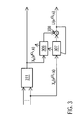
- Figure 1 shows a system for noise compensation in an audio signal comprising microphones 105.
- the microphones 105 are configured to detect a wanted signal of a wanted sound source, for example, a speech signal.
- a first microphone outputs a first audio signal on a first signal path.
- the first signal path connects the output of the first microphone with a first combining means 110.
- a second microphone 105 outputs a second audio signal on a second signal path.
- the first signal path branches off to an intermediate signal path comprising a first adaptive filtering means 106.
- the first audio signal is used as input for the first adaptive filtering means 106.
- the first adaptive filtering means 106 is used to filter the first audio signal to obtain a first filtered audio signal.
- the second audio signal on the second signal path is filtered by a second adaptive filtering means 107 to obtain a second filtered audio signal.
- the first filtered audio signal and the second filtered audio signal are combined using a second combining means 108.
- the first filtered audio signal may be subtracted from the second filtered audio signal.
- the output of the combining means 108 may correspond to a noise reference signal, wherein the first and the second adaptive filtering means 106 and 107 are adapted such as to minimize a wanted signal component in the noise reference signal.
- the noise reference signal is used as input for a third adaptive filtering means 109 in the second signal path to obtain a filtered noise reference signal.
- the filtered noise reference signal may correspond to an estimate of the noise component in the first audio signal.
- the first combining means 110 may be used to subtract the filtered noise reference signal output by the third adaptive filtering means 109 from the first audio signal on the first signal path.
- the third adaptive filtering means 109 may be adapted such as to minimize the noise component in the first audio signal. In this way, the combining means 110 yield an output signal with reduced noise.
- the first audio signal may comprise a wanted signal component, wherein the wanted signal component is associated with a wanted signal originating from a wanted sound source.
- a first transfer function 101 may model the transfer between the wanted signal and the first signal path, in particular the wanted signal component of the first audio signal on the first signal path.
- the first audio signal may comprise a noise component 103 originating from one or more noise sources.
- the second audio signal may comprise a wanted signal component associated with the wanted signal, in particular the wanted signal associated with the wanted signal component of the first audio signal.
- a second transfer function 102 may model the transfer between the wanted signal and the second signal path.
- the second audio signal may further comprise a noise component 104.
- the first and the second adaptive filtering means 106 and 107 may be adapted such as to minimize a wanted signal component in the noise reference signal, in particular according to a predetermined criterion.
- the first adaptive filtering means models the second transfer function
- the second adaptive filtering means models the first transfer function, i.e. the transfer function of the adjacent signal path or channel.
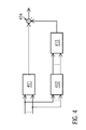
- Figure 2 shows a system for determining a noise reference signal comprising a first adaptive filtering means 206 and a second adaptive filtering means 207.
- the two adaptive filtering means may correspond to adaptive finite impulse response (FIR) filters.
- An output signal of the first adaptive filtering means 206 i.e. a first filtered audio signal
- an output signal of the second adaptive filtering means 207 i.e. a second filtered audio signal, using a combining means 208 to obtain a noise reference signal.
- ⁇ ⁇ denotes the ⁇ -th sub-band, in particular frequency nodes of the ⁇ -th sub-band.
- L and P denote the filter order of the adaptive filtering means
- k corresponds to a time variable
- the operator denoted by T corresponds to a transposition operator.
- the first and the second adaptive filtering means may be used to filter a first and a second audio signal, wherein the first audio signal is denoted by X B ( e j ⁇ ⁇ , k ) and the second audio signal is denoted by X A ( e j ⁇ ⁇ , k ).
- the first and the second audio signal may correspond to microphone signals.
- the first or the second audio signal may correspond to an output signal of a beamformer, i.e. to a beamformed signal.
- the beamformed signal may be determined by a beamformer based on microphone signals from a microphone array.
- the beamformed signal may be used as a first audio signal, while the second audio signal may be an arbitrary microphone signal from the microphone array, i.e.
- X A e j ⁇ ⁇ ⁇ ⁇ k : X m e j ⁇ ⁇ ⁇ ⁇ k
- X B e j ⁇ ⁇ ⁇ ⁇ k : X FBF e j ⁇ ⁇ ⁇ ⁇ k
- X FBF denotes a beamformed signal stemming from a fixed beamformer
- m denotes a predetermined or arbitrary microphone from the microphone array.
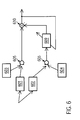
- FIG. 3 Such a system is shown in Figure 3 comprising a fixed beamformer 311, a first adaptive filtering means 306, a second adaptive filtering means 307 and a combining means 308, configured to combine the first filtered audio signal and the second filtered audio signal to yield a noise reference signal, U.
- the noise reference signal may be determined for a particular time, e.g. denoted by k.
- the first audio signal and the second audio signal may cover a predetermined time period.
- a noise reference signal may be determined repeatedly, in particular for different audio signals or for audio signals associated with different time periods and/or sub-bands.
- the filter coefficients of the adaptive filtering means may be updated or modified. In this way, the first and second adaptive filtering means may be adapted for a subsequent time.
- Adapting the first and the second adaptive filtering means may be based on a predetermined criterion, in particular, on a predetermined optimization criterion.
- This adaptation may comprise a gradient descent method, also known as steepest descent or method of steepest descent.
- updated or modified filter coefficients may be obtained, i.e. H A e j ⁇ ⁇ ⁇ ⁇ l ⁇ k ⁇ H ⁇ A ⁇ e j ⁇ ⁇ ⁇ , l , k + 1 , H B e j ⁇ ⁇ ⁇ ⁇ p ⁇ k ⁇ H ⁇ B ⁇ e j ⁇ ⁇ ⁇ , p , k + 1 .
- the modified coefficients may be normalized using a predetermined normalization factor, i.e. H ⁇ A ⁇ e j ⁇ ⁇ ⁇ , l , k + 1 ⁇ H A ⁇ e j ⁇ ⁇ ⁇ , l , k + 1 , H ⁇ B ⁇ e j ⁇ ⁇ ⁇ , p , k + 1 ⁇ H B ⁇ e j ⁇ ⁇ ⁇ , p , k + 1 .
- a predetermined normalization factor i.e. H ⁇ A ⁇ e j ⁇ ⁇ , l , k + 1 ⁇ H A ⁇ e j ⁇ ⁇ , l , k + 1 , H ⁇ B ⁇ e j ⁇ ⁇ ⁇ , p , k + 1 .
- Adapting the first and the second adaptive filtering means may be performed after the steps of filtering the first and the second audio signal.
- adapting the first and the second adaptive filtering means may be based on the normalized least mean square algorithm (NLMS, see e.g. "A sub-band based acoustic source localization system for reverberant environments" by T. Wolff, M. Buck and G. Schmidt, in Proc. ITG-Fachtagung pikommunikation, Aachen, October 2008).
- NLMS normalized least mean square algorithm
- This parameter may be determined or chosen from a predetermined range, in particular between 0 and 1, for example 0.5. While the wanted sound source is inactive, i.e. if the first and the second audio signal do not comprise a wanted signal component, the parameter ⁇ may be chosen equal to zero.
- the predetermined criterion for adapting the first and the second adaptive filtering means may be based on optimizing, in particular minimizing, the signal-to-noise ratio of the noise reference signal.
- the filter coefficient vector and the audio signal vector may be augmented by further audio signals, X c , and further filter coefficients, H c , for further adaptive filtering means, respectively, with c ⁇ ⁇ C , D ,... ⁇ .
- the combination of the filtered audio signals to obtain noise reference signals may be determined by the sign of the filter coefficients.
- E ⁇ ... ⁇ denotes an expectation value
- H denotes an Hermitian transpose (i.e. complex conjugate transpose).
- the method may comprise detecting whether the wanted sound source is active, i.e. whether the first and the second audio signal comprise a wanted signal component.
- the signal-to-noise ratio may be minimized, i.e. the power or power density of the wanted signal component in the noise reference signal may be minimized.
- the predetermined criterion for the adapted first and second adaptive filtering means or for adapting the first and the second adaptive filtering means may read: min H ⁇ e j ⁇ ⁇ ⁇ ⁇ k H ⁇ H e j ⁇ ⁇ ⁇ k ⁇ ⁇ XX e j ⁇ ⁇ ⁇ ⁇ k ⁇ H ⁇ e j ⁇ ⁇ ⁇ k H ⁇ H e j ⁇ ⁇ ⁇ k ⁇ nn e j ⁇ ⁇ ⁇ ⁇ k ⁇ H ⁇ e j ⁇ ⁇ ⁇ ⁇ k - 1
- the power of the noise component in the noise reference signal is set equal to the mean power of the noise component in the first and the second audio signal.
- Such a constraint is particularly useful when minimizing a wanted signal component in the noise reference signal.
- the algorithm for adapting the first and the second adaptive filtering means may be based on a gradient decent method and a Lagrangian method, i.e. based on Lagrange multipliers, (see e.g. "Adaptive Filter-and-Sum Beamforming in Spatially Correlated Noise” by E. Warsitz and R. Häb-Umbach, in Proc. Int. Workshop on Acoustic Echo and Noise Control (IWAENC-05), Eindhoven, 2005, pp. 125 - 128 ).
- the adaptation step size ⁇ (k) may take a positive value if the wanted sound source is active, in particular between 0 and 1, for example 0.5, while if the wanted sound source is inactive, i.e. if the audio signals comprise no wanted signal component, the adaptation increment, ⁇ (k), may be zero.
- P x ( k ) denotes a (temporally) smoothed power or power density of the first and the second audio signal or of the audio signal vector. The frequency dependency of all the terms in the algorithm was not explicitly noted to improve legibility.
- the sign of ⁇ (k) may be chosen such as to yield a minimization of the signal-to-noise ratio.
- the modified filter coefficients may be normalized.
- the adaptation may be further based on a predetermined normalization factor, ⁇ ( e j ⁇ ⁇ , k ) , i.e.
- H A e j ⁇ ⁇ ⁇ ⁇ l ⁇ k H ⁇ A e j ⁇ ⁇ ⁇ ⁇ l ⁇ k ⁇ ⁇ - 1 e j ⁇ ⁇ ⁇ ⁇ k
- H B e j ⁇ ⁇ ⁇ ⁇ p ⁇ k H ⁇ B e j ⁇ ⁇ ⁇ ⁇ p ⁇ k ⁇ ⁇ - 1 e j ⁇ ⁇ ⁇ ⁇ k .
- the predetermined normalization factor is real valued.
- phase correction By using a complex valued predetermined normalization factor, a phase correction can be performed as well.
- the first audio signal corresponds to an output signal of the beamformer 311, i.e. a beamformed signal.
- the second audio signal corresponds to a microphone signal from one of the M microphones of the microphone array.
- a noise reference signal may be determined for each of the M microphones of the microphone array in combination with the beamformed signal.
- a complex valued predetermined normalization factor based on a modified filter coefficient H ⁇ B ( e j ⁇ ⁇ , i 0 , k ) corresponding to H B ( e j ⁇ ⁇ , i 0 , k ) 1, may be advantageous as in this case the component X FBF ( e j ⁇ ⁇ , k - i 0 ) of the signal vector is not altered or modified by the first adaptive filtering means, and therefore is the same in all noise reference signals of the microphone array.
- the M noise reference signals of the microphone array are related to each other and may be compared to each other in terms of amplitude and phase differences.
- the predetermined normalization factor is based on a filter coefficient H A ( e j ⁇ ⁇ , i 0 , k ) of the second adaptive filtering means this might not be the case, as then different components X m ( e j ⁇ ⁇ , k - i 0 ) of the signal vector would be multiplied with the normalized filter coefficients.
- the predetermined normalization factor may be based on the power or power density of the noise component of a beamformed signal, wherein the beamformed signal may correspond to the first or the second audio signal.
- ⁇ vv ( e j ⁇ ⁇ , k ) denotes the power or power density of the noise component in the beamformed signal
- ⁇ u n u n ( e j ⁇ ⁇ , k ) denotes the power or power density of the noise component in the noise reference signal.
- the power density or the power of the beamformed signal i.e. the output signal of the beamformer, may be directly compared to the power density or power of the blocking signal. In this way, activity of the wanted sound source may be detected.
- a normalization of the filter coefficients may be omitted, as the constraint under which the minimization has been performed, may comprise an implicit normalization.
- Figure 8 shows the mean attenuation of the wanted signal component in the noise reference signal for different methods for determining the noise reference signal.
- a microphone array comprising two microphones was used to detect a wanted sound signal in a conference room.
- the filter order or filter length of the adaptive filtering means has been chosen to be 1.
- the determination of the noise reference signals was performed in a sub-band domain.
- time dependent audio signals were sampled with a sampling frequency of 11025 Hz and processed into 256 sub-bands.
- the direction to the wanted sound source in particular the direction of arrival of a wanted signal originating from the wanted sound source, was perpendicular to the axis of the microphone array, i.e. a "broadside" arrangement was used.
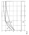
- Fig. 9 the same quantity is shown for different filter orders of the adaptive filtering means.
- the abscissa i.e. the x-axis, shows the filter order of the applied adaptive filtering means.
- the dotted line 930 corresponds to a system using a fixed blocking matrix. In this case, no adaptive filtering means are used.
- the dashed line 931 corresponds to a system using an adaptive blocking matrix.
- the dash-dotted line 932 corresponds to a system as shown in Fig. 2 and the solid line 933 corresponds to a system as shown in Fig. 3 .
- a method for determining a noise reference signal i.e. a signal where the wanted signal component is minimized or blocked, as described above, may be used for noise compensation, in particular in a "general sidelobe canceller" structure.
- the determined noise reference signal may also be used for post filtering of an audio signal, in particular for noise reduction.
- Another application of a noise reference signal can be found in the field of speech recognition or in the field of adaptation control.
- the activity of a wanted sound source may be detected.
- Such information on the activity of a wanted sound source may be used, for example, to control an adaptation process of an adaptive filtering means.
- a noise reference signal may be used to avoid disturbances in the speech signal by concurrently speaking users.
Abstract
Description
- The present invention relates to a method for determining a noise reference signal for noise compensation and/or noise reduction.
- Noise compensation and/or noise reduction in acoustic signals is an important issue, for example, in the field of speech signal processing. The quality of an audio signal, e.g. of a speech signal, is often impaired by various interferences stemming from different noise sources. Hands-free telephony systems or speech recognition systems, for instance, may be used in a noisy environment such as in a vehicular cabin. In this case, the voice signal may be interfered by background noise such as noise of the engine or noise of the rolling tires. Noise compensation methods may be used to compensate for the background noise thereby improving the signal quality and reducing misrecognitions.
- Common methods for noise compensation and/or noise reduction usually involve multi-channel systems. For example, two-channel systems are used, wherein a first channel comprises a disturbed audio signal and a second channel comprises a noise reference signal.
-
Figure 6 shows an example of such a system. Twomicrophones 605 are configured to detect a wanted signal of a wanted sound source, for example, a speech signal. A first microphone signal is output by a first microphone on a first signal path and a second microphone signal is output by a second microphone on a second signal path. The first and the second microphone signal comprise anoise component second transfer function interference canceller 609, which comprises an adaptive filtering means and determines an estimate for the noise component in the first microphone signal based on the second microphone signal. The output of theinterference canceller 609 is subtracted from the first microphone signal by a combiningmeans 610, thereby obtaining an output signal with reduced noise. The quality of the output signal depends on the wanted signal component in the second microphone signal. - In an ideal case, the second microphone signal and hence the output of the
interference canceller 609 do not comprise a wanted signal component. The quality of noise compensation in the output signal with reduced noise, however, also depends on the correlation between thenoise components interference canceller 609 is a bad estimate for the noise component of the first microphone signal and that therefore the quality of the output signal with reduced noise is low. To achieve a higher correlation, and hence a better estimate for the noise reference signal, the twomicrophones 605 should have a small relative distance from each other. As a consequence, however, the second microphone signal will also comprise a significant wanted signal component. - In order to solve this problem, current multi-channel systems primarily make use of a so-called "blocking matrix" in order to block a wanted signal component in the second signal path.
-
Figure 7 shows such a system comprising twomicrophones 705, aninterference canceller 709 and a first combining means 710 configured to subtract the estimate of the noise component from a first microphone signal. The first microphone signal from a first signal path may be used as input for an adaptive filtering means 715. The output of the adaptive filtering means 715 may be combined with a second microphone signal using asecond combining means 716, thereby obtaining a noise reference signal on a second signal path. This noise reference signal may be used as an input for theinterference canceller 709 and the output of theinterference canceller 709 may be subtracted from the first microphone signal using combiningmeans 710 to obtain an output signal with reduced noise. The first and the second microphone signal may comprise anoise component - A
first transfer function 701 modeling the transfer between a wanted signal and the first microphone signal on the first signal path may be denoted by G1(ejΩ) and asecond transfer function 702 modeling the transfer between the wanted signal and the second microphone signal on the second signal path may be denoted by G2(ejΩ). Here j denotes the imaginary unit and Q denotes a frequency variable. In order to obtain a noise reference signal with little or no wanted signal component, a transfer function, H, of the adaptive filtering means 715 may read
- In other words, the above-described transfer function of the adaptive filtering means 715 comprises an inverse of the first transfer function. This can yield an impaired noise reference signal if the value of the first transfer function approaches zero.
- Other known methods for determining a noise reference signals may similarly yield an impaired noise reference signal. The quality of noise compensation and/or noise reduction, however, depends to a large extent on the quality of the noise reference signal. Therefore, there is the need to provide a method for determining a more accurate noise reference signal for noise compensation and/or noise reduction.
- It is therefore the problem underlying the present invention to overcome the above mentioned drawback and to provide a method and a system for determining an accurate noise reference signal for noise compensation and/or noise reduction.
- The problem is solved by a method according to claim 1 and by a system according to claim 14.
- According to the present invention, a method for determining a noise reference signal for noise compensation and/or noise reduction, comprises the steps of:
- receiving a first audio signal on a first signal path and a second audio signal on a second signal path,
- filtering the first audio signal using a first adaptive filtering means to obtain a first filtered audio signal,
- filtering the second audio signal using a second adaptive filtering means to obtain a second filtered audio signal, and
- combining the first and the second filtered audio signal to obtain the noise reference signal,
- wherein the first and the second adaptive filtering means are adapted such as to minimize a wanted signal component in the noise reference signal.
- By using two adaptive filtering means to determine the noise reference signal, a wanted signal component in the noise reference signal can be effectively minimized. In this way, the quality of the noise reference signal can be improved compared to prior art methods.
- The method may be performed in the frequency domain, in particular in a sub-band domain. In the frequency domain, each of the first audio signal and the second audio signal may correspond to one or more short-time spectra. In this case, the first audio signal and the second audio signal correspond to a first audio signal spectrum and a second audio signal spectrum, respectively. The first and the second audio signal may be determined using short-time Fourier transforms of time-dependent audio signals. In this case, each of the first and the second audio signal correspond to a plurality of short-time Fourier coefficients, in particular for predetermined frequency nodes.
- Each of the first and the second filtered audio signal and the noise reference signal may correspond to a short-time spectrum as well.
- Alternatively, the method may be performed in the time domain, in particular in a discrete time domain.
- The first and the second audio signal generally comprise a noise component and may comprise a wanted signal component. Consequently, also the first and the second filtered audio signal generally comprise a noise component and may comprise a wanted signal component.
- The wanted signal component may be based on a wanted signal originating from a wanted sound source. In particular, the wanted signal from the wanted sound source may be received by a microphone array, in particular wherein the microphone array comprises at least two microphones. The wanted sound source may have a variable distance from the microphone array. The first and the second audio signal may correspond to or be based on microphone signals emanating from at least two microphones of the microphone array.
- One or more short-time spectra of the first and the second audio signal may comprise only a noise component. In this case, the wanted sound source may be temporarily inactive. The method may comprise detecting whether the first and/or the second audio signal comprise a wanted signal component. In other words, the method may comprise detecting whether the wanted sound source is active, in particular based on the noise reference signal. If no short time spectrum of the first and the second audio signal comprises a wanted signal component, the wanted sound source is inactive. In this case, no noise compensation may be performed.
- If the first and the second audio signal comprise a wanted signal component, also the noise reference signal may comprise a wanted signal component, wherein the first and the second adaptive filtering means are adapted such as to minimize the wanted signal component in the noise reference signal. A wanted signal component in the noise reference signal may be minimized such that it vanishes or that it falls below a predetermined detection threshold.
- The first and the second adaptive filtering means may be adapted according to a predetermined criterion, in particular according to a predetermined optimization criterion. The predetermined criterion may be based on a normalized least mean square method or on a method based on a minimization of the signal-to-noise ratio of the noise reference signal. In particular, the predetermined criterion may be based on the signal-to-noise ratio of the noise reference.
- Filtering the first audio signal may be performed on an intermediate signal path, wherein the intermediate signal path connects the first and the second signal path. In other words, the first adaptive filtering means may be arranged on an intermediate signal path connecting the first and the second signal path. Filtering the second audio signal and combining the first and the second filtered audio signal may be performed on the second signal path.
- A first transfer function may model a transfer from a wanted signal originating from a wanted sound source to the first signal path and a second transfer function may model a transfer from the wanted signal originating from the wanted sound source to the second signal path, wherein the transfer function of the first adaptive filtering means may be based on the second transfer function and/or wherein the transfer function of the second adaptive filtering means may be based on the first transfer function.
- In general, a transfer function may model a relation between an input and an output signal of a system. In particular, the transfer function applied to an input signal may yield the output signal of the system. In this case, the first transfer function may model the relation between a wanted signal originating from a wanted sound source and the first audio signal, in particular the wanted signal component of the first audio signal. The second transfer function may model the relation between the wanted signal originating from the wanted sound source and the second audio signal, in particular the wanted signal component of the second audio signal.
- A transfer function in the frequency domain may correspond to or be associated with an impulse response in the time domain.
- The transfer function of the first and/or the second adaptive filtering means may be further based on a predetermined or arbitrary transfer function. In particular, the transfer function of the first adaptive filtering means may be based on a combination, in particular on a product, of the second transfer function and a predetermined or arbitrary transfer function. The transfer function of the second adaptive filtering means may be based on a combination, in particular on a product, of the first transfer function and the predetermined or arbitrary transfer function. In other words, the transfer function of the first adaptive filtering means may model a combination of the second transfer function and an arbitrary transfer function and the transfer function of the second adaptive filtering means may model a combination of the first transfer function and the arbitrary transfer function. The predetermined or arbitrary transfer function may be the same for the transfer function of the first adaptive filtering means and the transfer function of the second adaptive filtering means.
- For example, the transfer function of the first and the second adaptive filtering means, H1 and H2, respectively, may read:

and
- Here G 1(e jΩ, k) denotes the first transfer function, G 2(e jΩ, k) denotes the second transfer function and G̃(e jΩ, k) denotes the arbitrary or predetermined transfer function. The parameter Ω denotes a frequency variable, for example a frequency node or frequency sampling point of a sub-band, j denotes the imaginary unit and k denotes the time.
- The arbitrary or predetermined transfer function may be constant. In particular, the arbitrary transfer function may be equal to 1. In this case, the transfer function of the first adaptive filtering means models the second transfer function and the transfer function of the second adaptive filtering means models the first transfer function.
- The transfer function of the first and/or the second adaptive filtering means may be modeled by filter coefficients of the first and/or the second adaptive filtering means. In other words, filter coefficients of the first and the second adaptive filtering means may be adapted such as to model an above-described transfer function of the first and the second adaptive filtering means. In particular, the filter coefficients of the first and the second adaptive filtering means may be adapted such as to minimize a wanted signal component in the noise reference signal by modeling a transfer function as described above.
- The above-described methods for determining a noise reference signal may comprise adapting the first and the second adaptive filtering means. Adapting the first and the second adaptive filtering means may comprise modifying or updating a filter coefficient or a set of filter coefficients of the first and/or the second adaptive filtering means to obtain a modified filter coefficient or a set of modified filter coefficients. Adapting the first and the second adaptive filtering means may be based on a predetermined criterion such as the above-described predetermined criterion, in particular on a predetermined optimization criterion.
- Adapting the first and the second adaptive filtering means may be based on a normalized least mean square method or on a method based on a minimization of the signal-to-noise ratio of the noise reference signal. In other words, the predetermined criterion may be based on a normalized least mean square method or on a method based on a minimization of the signal-to-noise ratio of the noise reference signal.
- The normalized least mean square method may comprise modifying a set of filter coefficients of the first and/or second adaptive filtering means based on the noise reference signal and/or based on the power or power density of the first and/or the second audio signal. The power density may correspond to a power spectral density. The normalized least mean square method may comprise determining a product of the first or the second audio signal and the noise reference signal, in particular, the complex conjugate of the noise reference signal. In particular, the normalized least mean square method may comprise modifying one or more filter coefficients of the first and/or the second adaptive filtering means by adding an adaptation term.
- The adaptation term may comprise a ratio between the product of the first or second audio signal with the noise reference signal, in particular, the complex conjugate of the noise reference signal, and the power or power density of the first and second audio signal, in particular the sum of the power or power density of the first and second audio signal. The adaptation term may comprise a free parameter, in particular corresponding to an adaptation step size. The value of the free parameter may lie within a predetermined range. The sign of the free parameter may be different for the adaptation terms associated with the filter coefficients of the first and the second adaptive filtering means.
- The method based on a minimization of the signal-to-noise ratio may comprise determining a power or power density of the first and of the second audio signal and/or determining a power or power density of the noise component of the first and of the second audio signal. The first and the second audio signal may be combined to an audio signal vector. In particular, the audio signal vector may comprise the one or more short-time spectra of the first and the second audio signal. In this case, the power or power density of the first and of the second audio signal may correspond to the power or power density of the audio signal vector.
- The filter coefficients of the first and the second adaptive filtering means may be combined to a filter coefficient vector. In this case, the noise reference signal may correspond to a product of the Hermitian transpose of the filter coefficient vector and the audio signal vector. The Hermitian transpose of a vector may correspond to the transposed and complex conjugated vector.
- The power density of the audio signal vector may correspond to the expectation value of the product between the audio signal vector and the Hermitian transposed of the audio signal vector. In this case, the power density corresponds to a power density matrix.
- The audio signal vector may correspond to a sum of a wanted signal vector and a noise vector, wherein the wanted signal vector comprises the wanted signal components of the first and of the second audio signal and the noise vector comprises the noise components of the first and of the second audio signal. If the wanted sound source is inactive, the audio signal vector corresponds to the noise vector. In this case, a power density matrix of the noise vector may be estimated or determined.
- An average or mean power or power density of the noise vector, in particular of the noise components of the first and of the second audio signal, may be determined based on the trace of the power density matrix of the noise vector.
- The signal-to-noise ratio of the noise reference signal may correspond to a ratio between a wanted signal component in the noise reference signal and a noise component in the noise reference signal, in particular between the power or power density of the wanted signal component in the noise reference signal and the power or power density of the noise component in the noise reference signal.
- The method based on a minimization of the signal-to-noise ratio may comprise minimizing the signal-to-noise ratio of the noise reference signal. In this way, a wanted signal component in the noise reference signal can be minimized. In other words, the predetermined optimization criterion may correspond to a minimization of the signal-to-noise ratio of the noise reference signal.
- Minimizing the signal-to-noise ratio may comprise determining the signal-to-noise ratio based on the power or power density of the first and the second audio signal and on the power or power density of the noise component of the first and second audio signal.
- Minimizing the signal-to-noise ratio of the noise reference signal may be based on the power or power density of the first and the second audio signal and on the power or power density of the noise component of the first and second audio signal. In particular, minimizing the signal-to-noise ratio of the noise reference signal may be based on the power density matrix of the audio signal vector and on the power density matrix of the noise vector. In this case, the method may comprise determining the power density matrix of the audio signal vector and the power density matrix of the noise vector.
- Minimizing the signal-to-noise ratio may be based on a constraint for the power or power density of the noise component in the noise reference signal. In particular, the power or power density of the noise component in the noise reference signal may be equal to the mean power or mean power density of the noise components in the first and second audio signal.
- Minimizing the signal-to-noise ratio may be based on a Lagrangian method, i.e. based on Lagrange multipliers, and/or on a method based on a gradient descent. In particular, a Lagrangian method may be used for minimizing the signal-to-noise ratio using a constraint.
- Adapting the first and the second adaptive filtering means may comprise normalizing modified filter coefficients of the first and/or the second adaptive filtering means using a predetermined normalization factor. In particular, a set of filter coefficients may be modified based on a normalized least mean square method or on a method based on a minimization of the signal-to-noise ratio of the noise reference signal as described above and thereafter, as a second step, normalized using a predetermined normalization factor. By normalizing the modified filter coefficients, an attenuation of the amplitude of the first and the second filtered audio signal may be avoided.
- The predetermined normalization factor may correspond to a scalar. The predetermined normalization factor may be based on one or more filter coefficients or on one or more modified filter coefficients of the first and/or the second adaptive filtering means. In particular, the predetermined normalization factor may correspond to the value of a predetermined modified filter coefficient of the first or the second adaptive filtering means. In this case, the predetermined normalization factor can be complex valued.
- The predetermined normalization factor may be based on an absolute value of a modified filter coefficient of the first or the second adaptive filtering means. In particular, the predetermined normalization factor may correspond to the absolute value of a predetermined modified filter coefficient of the first or the second adaptive filtering means. In this case, the predetermined normalization factor is real valued.
- The predetermined normalization factor may correspond to the maximum value of the absolute values of the modified filter coefficients of the first and the second adaptive filtering means.
- Alternatively, the predetermined normalization factor may be based on a linear combination of absolute values of modified filter coefficients of the first and the second adaptive filtering means. In particular, the predetermined normalization factor may correspond to a norm of the modified filter coefficients of the first and the second adaptive filtering means. In this case, the predetermined normalization factor may correspond to the square root of the sum of the squared absolute values of the modified filter coefficients of the first and of the second adaptive filtering means.
- If the wanted sound source is inactive, i.e. if the first and/or the second audio signal comprise no wanted signal component, the step of adapting the first and the second adaptive filtering means may be omitted.
- The first and the second adaptive filtering means may each correspond to adaptive finite impulse response (FIR) filters. The first and the second audio signal may correspond to a sequence of short-time spectra, in particular to a consecutive sequence. In particular, the first and the second audio signal may comprise a temporal sequence of short-time spectra. The number of short-time spectra in the sequence may correspond to the filter order or filter length of the employed filter. In other words, the number of short-time spectra in the first audio signal may be equal to the filter order of the first adaptive filtering means and the number of short-time spectra in the second audio signal may be equal to the filter order of the second adaptive filtering means.
- The first and the second audio signal may each be a microphone signal or a beamformed signal, in particular emanating from different microphones or beamformers. In other words, the first signal path may comprise at least one microphone and the second signal path may comprise at least one microphone, in particular wherein the at least one microphone of the second signal path differs from the at least one microphone of the first signal path. The first and/or second signal path may further comprise a beamformer. The first audio signal may correspond to an output signal of a microphone or to an output signal of a beamformer in the first signal path and the second audio signal may correspond to an output signal of a microphone or to an output signal of a beamformer in the second signal path.
- The predetermined normalization factor may be based on the power or power density of the noise component in the first or the second audio signal, in particular wherein the first or the second audio signal is a beamformed signal. In other words, the predetermined normalization factor may be based on the power or power density of a beamformed signal. The predetermined normalization factor may be proportional to the ratio between the power or power density of the noise component in the beamformed signal and the power or power density of the noise component in the noise reference signal. In particular, the predetermined normalization factor may be proportional to the square root of the ratio between the power or power density of the noise component in the beamformed signal and the power or power density of the noise component in the noise reference signal.
- If adapting the first and the second adaptive filtering means is based on a minimization of the signal-to-noise ratio of the noise reference signal, a normalization of the modified filter coefficients may be implicit in the constraint used for the minimization. In this case, a normalization of modified filter coefficients using a predetermined normalization factor may be omitted. The constraint for the minimization may be based on the power or power density of the beamformed signal.
- Combining the first and the second filtered audio signal may comprise subtracting the first filtered audio signal from the second filtered audio signal. In this way, the wanted signal component can be blocked in the second signal path. In other words, combining the first and the second filtered audio signal may correspond to blocking the wanted signal component in the second signal path. The noise reference signal may correspond to a blocking signal.
- The combination of the first and the second filtered audio signal to obtain the noise reference signal may be modeled by a blocking matrix. In this case, the blocking matrix applied to the first and the second audio signal yields the noise reference signal. In other words, the invention also provides a blocking matrix, wherein the blocking matrix comprises a transfer function of the first adaptive filtering means and a transfer function of the second adaptive filtering means, and wherein if the blocking matrix is applied to a first and a second audio signal a noise reference signal is obtained according to one of the above-described methods.
- The above-described methods may be performed for a plurality of audio signals, in particular stemming from different microphones of a microphone array. In this case, a blocking matrix applied to microphone signals of the microphone array may yield a plurality of noise reference signals, i.e. two or more noise reference signals. In particular, the first filtered audio signal may be combined with further audio signals, in particular pairwise, to obtain further noise reference signals. For example, the first filtered audio signal may be combined with a third filtered audio signal to obtain a second noise reference signal.
- The above-described methods may be performed repeatedly, in particular for subsequent audio signals. In particular, the first and the second audio signal may be associated with a predetermined time or time period. The above-described methods may be performed for a plurality of times or time periods, in particular for subsequent times or time periods.
- In this context, noise compensation may correspond to noise cancellation or noise suppression. In particular, a method for noise compensation may be used to cancel, suppress or compensate for noise in an audio signal, for example in the first audio signal.
- The invention further provides a method for processing an audio signal for noise compensation, comprising the steps of:
- determining a noise reference signal according to one of the above described methods, using a first audio signal on a first signal path and a second audio signal on a second signal path,
- filtering the noise reference signal on the second signal path using a third adaptive filtering means to obtain a filtered noise reference signal, and
- combining the first audio signal from the first signal path and the filtered noise reference signal to obtain an output signal with reduced noise.
- In this way, the noise component in the first audio signal may be minimized. In particular, combining the first audio signal and the filtered noise reference signal may comprise subtracting the filtered noise reference signal from the first audio signal.
- The first audio signal and the output signal with reduced noise may each comprise a signal component and a noise component, wherein the third adaptive filtering means is adapted such as to minimize the noise component in the output signal with reduced noise. The third adaptive filtering means may correspond to an FIR filtering means, in particular an adaptive FIR filter.
- By determining the noise reference signal according to one of the above described methods, the quality of noise compensation in the first audio signal may be improved compared to noise compensation based on a noise reference signal determined using prior art methods.
- The invention further provides a computer program product, comprising one or more computer readable media having computer executable instructions for performing the steps of one of the above described methods, when run on a computer.
- The invention further provides a system for audio signal processing, in particular configured to perform one of the above described methods, comprising receiving means for receiving a first and a second audio signal, a first adaptive filtering means to obtain a first filtered audio signal, a second adaptive filtering means to obtain a second filtered audio signal, and combining means for combining the first and the second filtered audio signal.
- The system allows to determine a noise reference signal according to one of the above described methods. In particular, the first and the second adaptive filtering means may be adapted such as to minimize a wanted signal component in an output signal of the combining means, i.e. in the noise reference signal.
- The system may be further configured to perform one of the above described methods for noise compensation.
- In particular, the system may further comprise a third adaptive filtering means to obtain a filtered noise reference signal. The combining means may correspond to a second combining means and the system may further comprise a first combining means for combining the first audio signal and the filtered noise reference signal. An output signal of the first combining means may correspond to an output signal with reduced noise. In particular, the third adaptive filtering means may be adapted such as to minimize a noise component in the output signal with reduced noise.
- In particular, the system may comprise:
- a microphone array comprising at least two microphones,
- wherein an output of a first microphone of the microphone array is connected to a first combining means on a first signal path and connected to a first adaptive filtering means on an intermediate signal path,
- an output of a second microphone of the microphone array connected to a second adaptive filtering means on a second signal path,
- an output of the first adaptive filtering means and an output of the second adaptive filtering means, both connected to a second combining means on the second signal path,
- an output of the second combining means connected to a third adaptive filtering means on the second signal path, and
- an output of the third adaptive filtering means connected to the first combining means.
- Such a system allows to compensate for noise in a first signal path based on a noise reference signal, wherein the noise reference signal may be obtained by blocking a wanted signal component in a second signal path. In particular, the second combining means and the first and the second adaptive filtering means may be configured such as to yield a noise reference signal according to one of the above-described methods. In this case, the output signal of the first microphone may correspond to the first audio signal and the output signal of the second microphone may correspond to the second audio signal.
- The third adaptive filtering means and the first combining means may be configured to yield an output signal with reduced noise according to one of the above-described methods.
- The system may further comprise a beamforming means, in particular an adaptive or a fixed beamformer, and/or an echo compensation means, in particular an adaptive echo canceller or acoustic echo canceller. A beamformer may be used for spatial filtering of audio signals. In this case, the microphone array may be connected to the beamformer. The beamformer may be arranged in the first signal path. In this case, an output of the beamformer may be connected to the first combining means on the first signal path and connected to the first adaptive filtering means on the intermediate signal path. In this case, an output signal of the beamformer in the first signal path corresponds to the first audio signal. Additionally or alternatively, a beamformer may be arranged in the second signal path. In this case, an output signal of the beamformer in the second signal path may correspond to the second audio signal.
- The system may further comprise means for speech synthesis or speech recognition.
- The system may be a hands-free system, in particular for use in a vehicle. The hands-free system may be a hands-free telephone set or a hands-free speech control set.
- Additional features and advantages of the present invention will be described with reference to the drawings. In the description, reference is made to accompanying figures that are meant to illustrate preferred embodiments of the invention.
- Figure 1
- shows a system for noise compensation comprising two adaptive filtering means for determining a noise reference signal;
- Figure 2
- shows a system for determining a noise reference signal comprising two adaptive filtering means;
- Figure 3
- shows a system for determining a noise reference signal comprising two adaptive filtering means and a beamformer;
- Figure 4
- shows a system for noise compensation comprising a beamformer, a blocking matrix and an interference canceller;
- Figure 5
- shows a system for noise compensation comprising a fixed beamformer;
- Figure 6
- shows a system for noise compensation comprising a first signal path and a second signal path;
- Figure 7
- shows a system for noise compensation comprising one adaptive filtering means for determining a noise reference signal;
- Figure 8
- shows the mean reduction of the wanted signal component in the noise refer- ence signal in different systems for noise compensation; and
- Figure 9
- shows the mean reduction of the wanted signal component in the noise refer- ence signal as a function of the filter order of the employed adaptive filtering means.
- To improve the signal quality of an audio signal, a method for noise compensation may be performed (see e.g. "Adaptive noise cancellation: Principles and applications" by B. Widrow et al., in Proc. of the IEEE, Vol. 63, No. 12, December 1975, pp. 1692 - 1716). In particular, the audio signal may be divided into sub-bands by some sub-band filtering means and a noise compensation method may be applied to each of the sub-bands. The method for noise compensation may utilize a multi-channel system, i.e. a system comprising a microphone array. Microphone arrays are also used in the field of source localization (see e.g. "Microphone Arrays for Video Camera Steering" by Y. Huang et al., in S. Gay, J. Benesty (Eds.), Acoustic Signal Processing for Telecommunication, Kluwer, Boston, 2000, pp. 239 - 259).
-
Figure 4 shows the general structure of a so-called "general sidelobe canceller" which comprises two signal processing paths: a first (or lower) adaptive signal path with a blockingmatrix 412 and aninterference canceller 413 and a second (or upper) non-adaptive signal path with a fixed beamformer 411 (see e.g. "Beamforming: a versatile approach to spatial filtering", by B. Van Veen and K. Buckley, IEEE ASSP Magazine, Vol. 5, No. 2, April 1988, pp. 4 - 24). An adaptive beamformer may be used instead of the fixedbeamformer 411. A combining means 414 may be used to subtract an output signal of theinterference canceller 413 from the beamformed signal. The blockingmatrix 412 may be used to estimate noise reference signals, wherein a noise reference signal comprises a minimized wanted signal component. In particular, the blockingmatrix 412 applied to microphone signals may yield the noise reference signals. The blockingmatrix 412 may be realized by adaptive filtering means and combining means as described above. Different kinds of blocking matrices may be used. - One example is a fixed blocking matrix (see, e.g. "An alternative approach to linearly constrained adaptive beamforming" by L. Griffiths and C. Jim, IEEE Trans. on Antennas and Propagation, Vol. 30, No. 1, January 1982, pp. 27 - 34). The fixed blocking matrix, however, relies on an idealized sound field, in which the wanted signal reaches the microphones of the microphone array as a plane wave from a predetermined direction. In practice, however, variations from the predetermined direction can occur, for example, due to reflections. As a consequence, the output signal of the combining means 414 may comprise a significant wanted signal component. One example for a fixed blocking matrix is the so-called "central difference matrix" which realizes a subtraction of audio signals from neighboring or adjacent channels or signal paths. For four microphone signals stemming from four different microphones, the fixed blocking matrix may read:

- Deviations from an idealized sound field may be compensated for by an adaptive blocking matrix which may be realized using adaptive filtering means. An example for a generalized sidelobe canceller with an adaptive blocking matrix, i.e. with adaptive filtering means is shown in
Figure 5 . In particular, afixed beamformer 511 is used on a first signal path in order to determine a beamformed signal from a plurality of microphone signals. A combining means 514 and aninterference canceller 513 may be used to compensate for a noise component in the beamformed signal. Theinterference canceller 513 may use noise reference signals to provide an estimate for the noise component in the beamformed signal. The noise reference signals may be determined using adaptive filtering means 515. - An adaptive blocking matrix is described in "A robust adaptive beamformer for microphone arrays with a blocking matrix using constrained adaptive filters" by O. Hoshuyama, A. Sugiyama and A. Hirano, in IEEE Transactions on Signal Processing, Vol. 47, No. 10, October 1999, pp. 2677 - 2684). In the frequency domain, without using constraints, this structure is described in "Computationally efficient frequency-domain robust generalized sidelobe canceller" by W. Herbordt and W. Kellermann, Proc. Int. Workshop on Acoustic Echo and Noise Control (IWAENC-01), Darmstadt, September 2001, pp. 51 - 55.
- Due to constraints for the filter coefficients of the adaptive filtering means associated with an adaptive blocking matrix, deviations from an idealized sound field may be compensated for only to a certain degree.
- Another example for a transfer function is given by a so-called "transfer function GSC", which considers an arbitrary transfer function from the wanted sound source to the microphone signals (see e.g. "Beamforming methods for multi-channel speech enhancement" by S. Gannot et al., Proc. Int. Workshop on Acoustic Echo and Noise Control (IWAENC-99), Pocono Manor PA, September 1999, pp. 96 - 99)
- In this approach, the transfer functions between a wanted signal originating from a wanted sound source and the microphone signals are being estimated by adaptive filtering means, i.e. inserted into a blocking matrix:

- In this way, a first microphone signal is combined with the other microphone signals by subtraction. In particular, the first microphone signal is divided by a transfer function modeling the transfer between the wanted signal and the first microphone signal and multiplied by a transfer function modeling the transfer between the wanted signal and the neighboring channel or microphone signal. This approach is similar to the adaptive blocking matrix, the first audio signal, however, corresponds to a microphone signal in this case, while to a beamformed signal in the former case.
- As such a blocking matrix comprises an inverse of a first transfer function modeling the transfer between the wanted signal and the first microphone signal, undesired artifacts in the noise reference signal may occur if the first transfer function approaches zero.
- As an alternative, systems with distributed microphones are known (see e.g. "Multichannel cross-talk cancellation in a call-center scenario using frequency domain adaptive filtering" by A. Lombard and W. Kellermann, in Proc. Int. Workshop on Acoustic Echo and Noise Control (IWAENC-08), Seattle, September 2008). In this case, it is assumed that a primary microphone receives the wanted signal from the wanted sound source in a more efficient way than the other microphones. A method similar to the one based on an adaptive blocking matrix may be used, wherein the microphone signal of the primary microphone instead of the beamformed signal is used as the first audio signal.
-
Figure 1 shows a system for noise compensation in an audiosignal comprising microphones 105. Themicrophones 105 are configured to detect a wanted signal of a wanted sound source, for example, a speech signal. In particular, a first microphone outputs a first audio signal on a first signal path. The first signal path connects the output of the first microphone with a first combining means 110. Asecond microphone 105 outputs a second audio signal on a second signal path. The first signal path branches off to an intermediate signal path comprising a first adaptive filtering means 106. The first audio signal is used as input for the first adaptive filtering means 106. The first adaptive filtering means 106 is used to filter the first audio signal to obtain a first filtered audio signal. The second audio signal on the second signal path is filtered by a second adaptive filtering means 107 to obtain a second filtered audio signal. The first filtered audio signal and the second filtered audio signal are combined using a second combining means 108. In particular, the first filtered audio signal may be subtracted from the second filtered audio signal. The output of the combining means 108 may correspond to a noise reference signal, wherein the first and the second adaptive filtering means 106 and 107 are adapted such as to minimize a wanted signal component in the noise reference signal. - The noise reference signal is used as input for a third adaptive filtering means 109 in the second signal path to obtain a filtered noise reference signal. The filtered noise reference signal may correspond to an estimate of the noise component in the first audio signal. The first combining means 110 may be used to subtract the filtered noise reference signal output by the third adaptive filtering means 109 from the first audio signal on the first signal path. In other words, the third adaptive filtering means 109 may be adapted such as to minimize the noise component in the first audio signal. In this way, the combining means 110 yield an output signal with reduced noise.
- The first audio signal may comprise a wanted signal component, wherein the wanted signal component is associated with a wanted signal originating from a wanted sound source. A
first transfer function 101 may model the transfer between the wanted signal and the first signal path, in particular the wanted signal component of the first audio signal on the first signal path. The first audio signal may comprise anoise component 103 originating from one or more noise sources. Similarly, the second audio signal may comprise a wanted signal component associated with the wanted signal, in particular the wanted signal associated with the wanted signal component of the first audio signal. Asecond transfer function 102 may model the transfer between the wanted signal and the second signal path. The second audio signal may further comprise anoise component 104. The first and the second adaptive filtering means 106 and 107 may be adapted such as to minimize a wanted signal component in the noise reference signal, in particular according to a predetermined criterion. - The adapted filter coefficients of the first and the second adaptive filtering means 106 and 107 may model the transfer function of the first and the second adaptive filtering means 106 and 107, respectively, which may read:


wherein G̃ denotes an arbitrary or predetermined transfer function. In other words, the solution for the transfer function of the first and second adaptive filtering means may not be unique. The predetermined or arbitrary transfer function may be constant, in particular, the arbitrary or predetermined transfer function may take a constant value of G̃ = 1. In this case, the first adaptive filtering means models the second transfer function and the second adaptive filtering means models the first transfer function, i.e. the transfer function of the adjacent signal path or channel. -
Figure 2 shows a system for determining a noise reference signal comprising a first adaptive filtering means 206 and a second adaptive filtering means 207. The two adaptive filtering means may correspond to adaptive finite impulse response (FIR) filters. An output signal of the first adaptive filtering means 206, i.e. a first filtered audio signal, may be combined with an output signal of the second adaptive filtering means 207, i.e. a second filtered audio signal, using a combining means 208 to obtain a noise reference signal. The filter coefficients modeling the transfer function of the first and second adaptive filtering means 206 and 207, respectively, may read:
and
wherein l denotes the filter order variable of the second adaptive filtering means 207, with l=0,...,L-1, and p denotes the filter order variable of the first adaptive filtering means 206, with p=0,...,P-1, with L and P denoting the filter order of the first and second adaptive filtering means. Here and below, Ωµ denotes the µ-th sub-band, in particular frequency nodes of the µ-th sub-band. - The filter coefficients may be written as a vector, i.e.

and
- In this case L and P denote the filter order of the adaptive filtering means, k corresponds to a time variable and the operator denoted by T corresponds to a transposition operator. The first and the second adaptive filtering means may be used to filter a first and a second audio signal, wherein the first audio signal is denoted by XB(e jΩ
µ , k) and the second audio signal is denoted by XA(e jΩµ ,k). A noise reference signal, U (e jΩµ , k), may be determined as:
- Here the operator * denotes a complex conjugation. The first and the second audio signal may correspond to microphone signals. In particular, in an array comprising M microphones, two arbitrary microphone signals may be used to determine a noise reference signal, i.e.

and
- With m ≠ n , denoting microphone m and n, respectively, in particular with m, n ∈ {1,...,M}.
- Alternatively, the first or the second audio signal may correspond to an output signal of a beamformer, i.e. to a beamformed signal. The beamformed signal may be determined by a beamformer based on microphone signals from a microphone array. For determining the noise reference signal the beamformed signal may be used as a first audio signal, while the second audio signal may be an arbitrary microphone signal from the microphone array, i.e.

and
where XFBF denotes a beamformed signal stemming from a fixed beamformer and m denotes a predetermined or arbitrary microphone from the microphone array. Such a system is shown inFigure 3 comprising afixed beamformer 311, a first adaptive filtering means 306, a second adaptive filtering means 307 and a combining means 308, configured to combine the first filtered audio signal and the second filtered audio signal to yield a noise reference signal, U. - The noise reference signal may be determined for a particular time, e.g. denoted by k. The first audio signal and the second audio signal may cover a predetermined time period.
- A noise reference signal may be determined repeatedly, in particular for different audio signals or for audio signals associated with different time periods and/or sub-bands.
- The filter coefficients of the adaptive filtering means may be updated or modified. In this way, the first and second adaptive filtering means may be adapted for a subsequent time.
- Adapting the first and the second adaptive filtering means may be based on a predetermined criterion, in particular, on a predetermined optimization criterion. This adaptation may comprise a gradient descent method, also known as steepest descent or method of steepest descent.
- In this way, updated or modified filter coefficients may be obtained, i.e.


- The modified coefficients may be normalized using a predetermined normalization factor, i.e.


- Adapting the first and the second adaptive filtering means may be performed after the steps of filtering the first and the second audio signal.
- In particular, adapting the first and the second adaptive filtering means may be based on the normalized least mean square algorithm (NLMS, see e.g. "A sub-band based acoustic source localization system for reverberant environments" by T. Wolff, M. Buck and G. Schmidt, in Proc. ITG-Fachtagung Sprachkommunikation, Aachen, October 2008). The normalized least mean square method is computationally efficient and robust. This algorithm may read:


wherein β denotes a free parameter, in particular corresponding to an adaption increment or adaptation step size. This parameter may be determined or chosen from a predetermined range, in particular between 0 and 1, for example 0.5. While the wanted sound source is inactive, i.e. if the first and the second audio signal do not comprise a wanted signal component, the parameter β may be chosen equal to zero. The adaptation terms comprise the power or power density of the first and the second audio signal in the denominator, which reads:
- Alternatively, the predetermined criterion for adapting the first and the second adaptive filtering means may be based on optimizing, in particular minimizing, the signal-to-noise ratio of the noise reference signal. In this case, a filter coefficient vector may be defined as:

and an audio signal vector may be defined as:
- The filter coefficient vector and the audio signal vector may be augmented by further audio signals, Xc, and further filter coefficients, Hc, for further adaptive filtering means, respectively, with c ∈ {C, D,...}. In this case, the combination of the filtered audio signals to obtain noise reference signals, may be determined by the sign of the filter coefficients.
- A noise reference signal, U, may be determined as

- From the audio signal vector, a power density matrix, in particular a power spectral density matrix, may be determined, i.e.

where the operator E{...} denotes an expectation value and the operator H denotes an Hermitian transpose (i.e. complex conjugate transpose). - In this way, the power spectral density of the noise reference signal may be written as


- The first and the second audio signal may comprise a wanted signal component and a noise component, i.e. the audio signal vector may correspond to a sum of a wanted signal vector and a noise vector, i.e.

- The wanted signal component and the noise component may be statistically independent. Consequently, the power spectral density matrix of the audio signal vector may read:

- The method may comprise detecting whether the wanted sound source is active, i.e. whether the first and the second audio signal comprise a wanted signal component. In particular, the power or power density of the noise component, i.e. of the noise vector, may be estimated during the wanted sound source is inactive, i.e. if the wanted signal component or vector is equal to zero (
S (e jΩµ , k) = 0). Then the power spectral density matrix of the noise vector reads:
- A mean power or mean power spectral density of the noise component, in particular of the first and second audio signal or of the noise vector, may be estimated as

- Here the operator trace{...} denotes the trace operator, i.e. the sum of the elements on the main diagonal of a square matrix. The power or power density of the wanted signal component and the noise component in the noise reference signal, φ u
s us and φ un un , respectively, may read:

- In this way, the signal-to-noise ratio (SNR) of the noise reference signal may read

- The signal-to-noise ratio may be minimized, i.e. the power or power density of the wanted signal component in the noise reference signal may be minimized. Hence the predetermined criterion for the adapted first and second adaptive filtering means or for adapting the first and the second adaptive filtering means may read:

- The optimization may comprise the constraint

- According to this constraint, the power of the noise component in the noise reference signal is set equal to the mean power of the noise component in the first and the second audio signal. Such a constraint is particularly useful when minimizing a wanted signal component in the noise reference signal.
- The algorithm for adapting the first and the second adaptive filtering means may be based on a gradient decent method and a Lagrangian method, i.e. based on Lagrange multipliers, (see e.g. "Adaptive Filter-and-Sum Beamforming in Spatially Correlated Noise" by E. Warsitz and R. Häb-Umbach, in Proc. Int. Workshop on Acoustic Echo and Noise Control (IWAENC-05), Eindhoven, 2005, pp. 125 - 128).
- The algorithm may read:

with
and
and the normalized adaptation step size or adaptation increment
- The adaptation step size α(k) may take a positive value if the wanted sound source is active, in particular between 0 and 1, for example 0.5, while if the wanted sound source is inactive, i.e. if the audio signals comprise no wanted signal component, the adaptation increment, α(k), may be zero.
P x (k) denotes a (temporally) smoothed power or power density of the first and the second audio signal or of the audio signal vector. The frequency dependency of all the terms in the algorithm was not explicitly noted to improve legibility. - The sign of µ(k) may be chosen such as to yield a minimization of the signal-to-noise ratio.
- As the transfer function of the first and the second adaptive filtering means is not unique, an attenuation of the amplitude of the filter coefficients may occur. In order to avoid such an attenuation, the modified filter coefficients may be normalized. In other words, the adaptation may be further based on a predetermined normalization factor, η(e jΩ
µ , k) , i.e.

- For the choice of the predetermined normalization factor, several alternatives are possible.
- For example, the predetermined normalization factor may correspond to the norm of a modified filter coefficient vector, i.e.

- Alternatively, the maximum value of the absolute values of the modified filter coefficients may be used, i.e.

- Alternatively, the absolute value of a predetermined modified filter coefficient may be used, i.e.

wherein the index c0 indicates the first or the second audio signal and the index i0 indicates the value of the filter order variable of the predetermined filter coefficient. In this case the predetermined normalization factor is real valued. - A complex valued predetermined normalization factor may be determined from a particular or predetermined modified filter coefficient, i.e.

- By using a complex valued predetermined normalization factor, a phase correction can be performed as well.
- Particularly for a system as shown in
Fig. 3 , it may be useful to use a predetermined modified filter coefficient from the first adaptive filtering means as predetermined normalization factor, in particular with the index i 0 = 0. InFig. 3 , the first audio signal corresponds to an output signal of thebeamformer 311, i.e. a beamformed signal. The second audio signal corresponds to a microphone signal from one of the M microphones of the microphone array. A noise reference signal may be determined for each of the M microphones of the microphone array in combination with the beamformed signal. A complex valued predetermined normalization factor based on a modified filter coefficient H̃B (e jΩµ , i 0, k) corresponding to HB (e jΩµ , i 0, k) = 1, may be advantageous as in this case the component XFBF (e jΩµ , k - i 0) of the signal vector is not altered or modified by the first adaptive filtering means, and therefore is the same in all noise reference signals of the microphone array. As a consequence, the M noise reference signals of the microphone array are related to each other and may be compared to each other in terms of amplitude and phase differences. In the case where the predetermined normalization factor is based on a filter coefficient HA (e jΩµ , i 0,k) of the second adaptive filtering means this might not be the case, as then different components Xm (e jΩµ , k - i 0) of the signal vector would be multiplied with the normalized filter coefficients. - The predetermined normalization factor may be based on the power or power density of the noise component of a beamformed signal, wherein the beamformed signal may correspond to the first or the second audio signal. In particular, the predetermined normalization factor may be proportional to the ratio between the power or power density of the noise component in the beamformed signal, i.e. at the output of the beamformer, and the power or power density of the noise component in the noise reference signal, for example,

- Here φ vv (e jΩ
µ , k) denotes the power or power density of the noise component in the beamformed signal and φ un un (e jΩµ , k) denotes the power or power density of the noise component in the noise reference signal. The power density or the power of the beamformed signal, i.e. the output signal of the beamformer, may be directly compared to the power density or power of the blocking signal. In this way, activity of the wanted sound source may be detected. - If adapting the first and the second adaptive filtering means is based on a minimization of the signal-to-noise ratio of the noise reference signal, a normalization of the filter coefficients may be omitted, as the constraint under which the minimization has been performed, may comprise an implicit normalization.
-
Figure 8 shows the mean attenuation of the wanted signal component in the noise reference signal for different methods for determining the noise reference signal. In particular, a microphone array comprising two microphones was used to detect a wanted sound signal in a conference room. The filter order or filter length of the adaptive filtering means has been chosen to be 1. The determination of the noise reference signals was performed in a sub-band domain. In particular, time dependent audio signals were sampled with a sampling frequency of 11025 Hz and processed into 256 sub-bands. - The direction to the wanted sound source, in particular the direction of arrival of a wanted signal originating from the wanted sound source, was perpendicular to the axis of the microphone array, i.e. a "broadside" arrangement was used. The decrease of the signal-to-noise ratio from the first and the second audio signal to the noise reference signal was determined. This decrease is shown on the ordinate of
Figure 8 , in particular as mean of the power attenuation (in dB), for a system using a fixedblocking matrix 820, i.e. B=[1,-1], a system using anadaptive blocking matrix 821, a system as shown inFig. 2 , 822, a system as shown inFig. 3 , 823, and a system wherein the first and the second adaptive filtering means have been adapted based on a minimization of the signal-to-noise ratio 824. The best blocking of the wanted signal component can be found for the signal-to-noiseratio minimization method 824. InFig. 9 , the same quantity is shown for different filter orders of the adaptive filtering means. In particular, the abscissa, i.e. the x-axis, shows the filter order of the applied adaptive filtering means. The dottedline 930 corresponds to a system using a fixed blocking matrix. In this case, no adaptive filtering means are used. The dashedline 931 corresponds to a system using an adaptive blocking matrix. The dash-dottedline 932 corresponds to a system as shown inFig. 2 and thesolid line 933 corresponds to a system as shown inFig. 3 . - A method for determining a noise reference signal, i.e. a signal where the wanted signal component is minimized or blocked, as described above, may be used for noise compensation, in particular in a "general sidelobe canceller" structure. The determined noise reference signal may also be used for post filtering of an audio signal, in particular for noise reduction. Another application of a noise reference signal can be found in the field of speech recognition or in the field of adaptation control. By comparing the noise reference signal to other signals such as a beamformed signal, the activity of a wanted sound source may be detected. Such information on the activity of a wanted sound source may be used, for example, to control an adaptation process of an adaptive filtering means.
- In a hands-free system with distributed microphones, a noise reference signal may be used to avoid disturbances in the speech signal by concurrently speaking users.
- Although previously discussed embodiments of the present invention have been described separately, it is to be understood that some or all of the above-described features can also be combined in different ways. The discussed embodiments are not intended as limitations but serve as examples illustrating features and advantages of the invention.
Claims (15)
- A method for determining a noise reference signal for noise compensation and/or noise reduction, comprising the steps of:receiving a first audio signal on a first signal path and a second audio signal on a second signal path;filtering the first audio signal using a first adaptive filtering means to obtain a first filtered audio signal;filtering the second audio signal using a second adaptive filtering means to obtain a second filtered audio signal; andcombining the first and the second filtered audio signal to obtain the noise reference signal;wherein the first and the second adaptive filtering means are adapted such as to minimize a wanted signal component in the noise reference signal.
- The method according to claim 1, wherein a first transfer function models a transfer from a wanted signal originating from a wanted sound source to the first signal path and a second transfer function models a transfer from the wanted signal originating from the wanted sound source to the second signal path, and wherein the transfer function of the first adaptive filtering means is based on the second transfer function and/or wherein the transfer function of the second adaptive filtering means is based on the first transfer function.
- The method according to claim 1 or 2, comprising adapting the first and the second adaptive filtering means.
- The method according to claim 3, wherein adapting the first and the second adaptive filtering means is based on a normalized least mean square method or on a method based on a minimization of the signal-to-noise ratio of the noise reference signal.
- The method according to claim 4, wherein the normalized least mean square method comprises modifying a set of filter coefficients of the first and/or second adaptive filtering means based on the noise reference signal and/or based on the power or power density of the first and second audio signal.
- The method according to claim 4, wherein the method based on the minimization of the signal-to-noise ratio comprises determining a power or power density of the first and the second audio signal and/or determining a power or power density of the noise component of the first and second audio signal.
- The method according to claim 6, wherein minimizing the signal-to-noise ratio of the noise reference signal is based on the power or power density of the first and the second audio signal and on the power or power density of the noise component of the first and second audio signal.
- The method according to any one of the claims 3 - 7, wherein adapting the first and the second adaptive filtering means comprises normalizing modified filter coefficients of the first and/or second adaptive filtering means using a predetermined normalization factor.
- The method according to claim 8, wherein the predetermined normalization factor is based on one or more filter coefficients or on one or more modified filter coefficients of the first and/or second adaptive filtering means.
- The method according to any one of the preceding claims, wherein the first and the second audio signal each are a microphone signal or a beamformed signal, in particular emanating from different microphones or beamformers.
- The method according any one of the preceding claims, wherein combining the first and the second filtered audio signal comprises subtracting the first filtered audio signal from the second filtered audio signal.
- A method for processing an audio signal for noise compensation, comprising the steps of:determining a noise reference signal according to one of the claims 1 - 11, using a first audio signal on a first signal path and a second audio signal on a second signal path;filtering the noise reference signal on the second signal path using a third adaptive filtering means to obtain a filtered noise reference signal; andcombining the first audio signal from the first signal path and the filtered noise reference signal to obtain an output signal with reduced noise.
- A computer program product, comprising one or more computer readable media having computer executable instructions for performing the steps of the method according to one of the preceding claims, when run on a computer.
- A system for audio signal processing configured to perform one of the methods according to claims 1 - 12, comprising:receiving means for receiving a first and a second audio signal;a first adaptive filtering means to obtain a first filtered audio signal;a second adaptive filtering means to obtain a second filtered audio signal; andcombining means for combining the first and the second filtered audio signal.
- The system according to claim 14, further comprising:a microphone array comprising at least two microphones;wherein an output of a first microphone of the microphone array is connected to a first combining means on a first signal path and connected to a first adaptive filtering means on an intermediate signal path;an output of a second microphone of the microphone array connected to a second adaptive filtering means on a second signal path;an output of the first adaptive filtering means and an output of the second adaptive filtering means, both connected to a second combining means on the second signal path;an output of the second combining means connected to a third adaptive filtering means on the second signal path; andan output of the third adaptive filtering means connected to the first combining means.
Priority Applications (3)
| Application Number | Priority Date | Filing Date | Title |
|---|---|---|---|
| EP09004609A EP2237270B1 (en) | 2009-03-30 | 2009-03-30 | A method for determining a noise reference signal for noise compensation and/or noise reduction |
| US12/749,066 US8374358B2 (en) | 2009-03-30 | 2010-03-29 | Method for determining a noise reference signal for noise compensation and/or noise reduction |
| US13/748,264 US9280965B2 (en) | 2009-03-30 | 2013-01-23 | Method for determining a noise reference signal for noise compensation and/or noise reduction |
Applications Claiming Priority (1)
| Application Number | Priority Date | Filing Date | Title |
|---|---|---|---|
| EP09004609A EP2237270B1 (en) | 2009-03-30 | 2009-03-30 | A method for determining a noise reference signal for noise compensation and/or noise reduction |
Publications (2)
| Publication Number | Publication Date |
|---|---|
| EP2237270A1 true EP2237270A1 (en) | 2010-10-06 |
| EP2237270B1 EP2237270B1 (en) | 2012-07-04 |
Family
ID=40658187
Family Applications (1)
| Application Number | Title | Priority Date | Filing Date |
|---|---|---|---|
| EP09004609A Active EP2237270B1 (en) | 2009-03-30 | 2009-03-30 | A method for determining a noise reference signal for noise compensation and/or noise reduction |
Country Status (2)
| Country | Link |
|---|---|
| US (2) | US8374358B2 (en) |
| EP (1) | EP2237270B1 (en) |
Cited By (5)
| Publication number | Priority date | Publication date | Assignee | Title |
|---|---|---|---|---|
| WO2013009949A1 (en) * | 2011-07-13 | 2013-01-17 | Dts Llc | Microphone array processing system |
| GB2521553A (en) * | 2009-08-15 | 2015-06-24 | Archiveades Georgiou | Method and system |
| US9245516B2 (en) | 2012-09-20 | 2016-01-26 | Aisin Seiki Kabushiki Kaisha | Noise removal device |
| US9607603B1 (en) | 2015-09-30 | 2017-03-28 | Cirrus Logic, Inc. | Adaptive block matrix using pre-whitening for adaptive beam forming |
| WO2017060673A1 (en) * | 2015-10-09 | 2017-04-13 | Cirrus Logic International Semiconductor Limited | Adaptive filter control |
Families Citing this family (80)
| Publication number | Priority date | Publication date | Assignee | Title |
|---|---|---|---|---|
| EP2237270B1 (en) | 2009-03-30 | 2012-07-04 | Nuance Communications, Inc. | A method for determining a noise reference signal for noise compensation and/or noise reduction |
| US9330675B2 (en) | 2010-11-12 | 2016-05-03 | Broadcom Corporation | Method and apparatus for wind noise detection and suppression using multiple microphones |
| US8908877B2 (en) | 2010-12-03 | 2014-12-09 | Cirrus Logic, Inc. | Ear-coupling detection and adjustment of adaptive response in noise-canceling in personal audio devices |
| JP5937611B2 (en) | 2010-12-03 | 2016-06-22 | シラス ロジック、インコーポレイテッド | Monitoring and control of an adaptive noise canceller in personal audio devices |
| CN103444094B (en) * | 2011-05-10 | 2016-06-08 | 三菱电机株式会社 | Adaptive equalizer, acoustic echo canceller device and active noise controller |
| US9824677B2 (en) | 2011-06-03 | 2017-11-21 | Cirrus Logic, Inc. | Bandlimiting anti-noise in personal audio devices having adaptive noise cancellation (ANC) |
| US8958571B2 (en) * | 2011-06-03 | 2015-02-17 | Cirrus Logic, Inc. | MIC covering detection in personal audio devices |
| US8948407B2 (en) | 2011-06-03 | 2015-02-03 | Cirrus Logic, Inc. | Bandlimiting anti-noise in personal audio devices having adaptive noise cancellation (ANC) |
| US9318094B2 (en) | 2011-06-03 | 2016-04-19 | Cirrus Logic, Inc. | Adaptive noise canceling architecture for a personal audio device |
| US9215328B2 (en) * | 2011-08-11 | 2015-12-15 | Broadcom Corporation | Beamforming apparatus and method based on long-term properties of sources of undesired noise affecting voice quality |
| US8903722B2 (en) * | 2011-08-29 | 2014-12-02 | Intel Mobile Communications GmbH | Noise reduction for dual-microphone communication devices |
| JP5903631B2 (en) * | 2011-09-21 | 2016-04-13 | パナソニックIpマネジメント株式会社 | Noise canceling device |
| CN102509552B (en) * | 2011-10-21 | 2013-09-11 | 浙江大学 | Method for enhancing microphone array voice based on combined inhibition |
| US9318090B2 (en) | 2012-05-10 | 2016-04-19 | Cirrus Logic, Inc. | Downlink tone detection and adaptation of a secondary path response model in an adaptive noise canceling system |
| US9319781B2 (en) | 2012-05-10 | 2016-04-19 | Cirrus Logic, Inc. | Frequency and direction-dependent ambient sound handling in personal audio devices having adaptive noise cancellation (ANC) |
| US9123321B2 (en) | 2012-05-10 | 2015-09-01 | Cirrus Logic, Inc. | Sequenced adaptation of anti-noise generator response and secondary path response in an adaptive noise canceling system |
| US9532139B1 (en) | 2012-09-14 | 2016-12-27 | Cirrus Logic, Inc. | Dual-microphone frequency amplitude response self-calibration |
| US9685171B1 (en) * | 2012-11-20 | 2017-06-20 | Amazon Technologies, Inc. | Multiple-stage adaptive filtering of audio signals |
| US9369798B1 (en) | 2013-03-12 | 2016-06-14 | Cirrus Logic, Inc. | Internal dynamic range control in an adaptive noise cancellation (ANC) system |
| US9414150B2 (en) | 2013-03-14 | 2016-08-09 | Cirrus Logic, Inc. | Low-latency multi-driver adaptive noise canceling (ANC) system for a personal audio device |
| US9813808B1 (en) * | 2013-03-14 | 2017-11-07 | Amazon Technologies, Inc. | Adaptive directional audio enhancement and selection |
| US9324311B1 (en) | 2013-03-15 | 2016-04-26 | Cirrus Logic, Inc. | Robust adaptive noise canceling (ANC) in a personal audio device |
| US10206032B2 (en) | 2013-04-10 | 2019-02-12 | Cirrus Logic, Inc. | Systems and methods for multi-mode adaptive noise cancellation for audio headsets |
| US9462376B2 (en) | 2013-04-16 | 2016-10-04 | Cirrus Logic, Inc. | Systems and methods for hybrid adaptive noise cancellation |
| US9478210B2 (en) | 2013-04-17 | 2016-10-25 | Cirrus Logic, Inc. | Systems and methods for hybrid adaptive noise cancellation |
| US9578432B1 (en) | 2013-04-24 | 2017-02-21 | Cirrus Logic, Inc. | Metric and tool to evaluate secondary path design in adaptive noise cancellation systems |
| EP2806424A1 (en) * | 2013-05-20 | 2014-11-26 | ST-Ericsson SA | Improved noise reduction |
| US9495968B2 (en) | 2013-05-29 | 2016-11-15 | Qualcomm Incorporated | Identifying sources from which higher order ambisonic audio data is generated |
| US9466305B2 (en) | 2013-05-29 | 2016-10-11 | Qualcomm Incorporated | Performing positional analysis to code spherical harmonic coefficients |
| US9666176B2 (en) | 2013-09-13 | 2017-05-30 | Cirrus Logic, Inc. | Systems and methods for adaptive noise cancellation by adaptively shaping internal white noise to train a secondary path |
| CN105706467B (en) | 2013-09-17 | 2017-12-19 | 韦勒斯标准与技术协会公司 | Method and apparatus for handling audio signal |
| US9620101B1 (en) | 2013-10-08 | 2017-04-11 | Cirrus Logic, Inc. | Systems and methods for maintaining playback fidelity in an audio system with adaptive noise cancellation |
| WO2015060652A1 (en) | 2013-10-22 | 2015-04-30 | 연세대학교 산학협력단 | Method and apparatus for processing audio signal |
| US9704472B2 (en) | 2013-12-10 | 2017-07-11 | Cirrus Logic, Inc. | Systems and methods for sharing secondary path information between audio channels in an adaptive noise cancellation system |
| US10382864B2 (en) | 2013-12-10 | 2019-08-13 | Cirrus Logic, Inc. | Systems and methods for providing adaptive playback equalization in an audio device |
| US10219071B2 (en) | 2013-12-10 | 2019-02-26 | Cirrus Logic, Inc. | Systems and methods for bandlimiting anti-noise in personal audio devices having adaptive noise cancellation |
| BR112016014892B1 (en) | 2013-12-23 | 2022-05-03 | Gcoa Co., Ltd. | Method and apparatus for audio signal processing |
| US9502045B2 (en) | 2014-01-30 | 2016-11-22 | Qualcomm Incorporated | Coding independent frames of ambient higher-order ambisonic coefficients |
| US9922656B2 (en) | 2014-01-30 | 2018-03-20 | Qualcomm Incorporated | Transitioning of ambient higher-order ambisonic coefficients |
| US9369557B2 (en) | 2014-03-05 | 2016-06-14 | Cirrus Logic, Inc. | Frequency-dependent sidetone calibration |
| KR102149216B1 (en) | 2014-03-19 | 2020-08-28 | 주식회사 윌러스표준기술연구소 | Audio signal processing method and apparatus |
| CN106165454B (en) | 2014-04-02 | 2018-04-24 | 韦勒斯标准与技术协会公司 | Acoustic signal processing method and equipment |
| US9510096B2 (en) * | 2014-05-04 | 2016-11-29 | Yang Gao | Noise energy controlling in noise reduction system with two microphones |
| US9852737B2 (en) | 2014-05-16 | 2017-12-26 | Qualcomm Incorporated | Coding vectors decomposed from higher-order ambisonics audio signals |
| US9620137B2 (en) | 2014-05-16 | 2017-04-11 | Qualcomm Incorporated | Determining between scalar and vector quantization in higher order ambisonic coefficients |
| US10770087B2 (en) | 2014-05-16 | 2020-09-08 | Qualcomm Incorporated | Selecting codebooks for coding vectors decomposed from higher-order ambisonic audio signals |
| US10181315B2 (en) | 2014-06-13 | 2019-01-15 | Cirrus Logic, Inc. | Systems and methods for selectively enabling and disabling adaptation of an adaptive noise cancellation system |
| US9478212B1 (en) | 2014-09-03 | 2016-10-25 | Cirrus Logic, Inc. | Systems and methods for use of adaptive secondary path estimate to control equalization in an audio device |
| CN105489224B (en) * | 2014-09-15 | 2019-10-18 | 讯飞智元信息科技有限公司 | A kind of voice de-noising method and system based on microphone array |
| US9747910B2 (en) | 2014-09-26 | 2017-08-29 | Qualcomm Incorporated | Switching between predictive and non-predictive quantization techniques in a higher order ambisonics (HOA) framework |
| US10127919B2 (en) * | 2014-11-12 | 2018-11-13 | Cirrus Logic, Inc. | Determining noise and sound power level differences between primary and reference channels |
| WO2016093855A1 (en) * | 2014-12-12 | 2016-06-16 | Nuance Communications, Inc. | System and method for generating a self-steering beamformer |
| US9552805B2 (en) | 2014-12-19 | 2017-01-24 | Cirrus Logic, Inc. | Systems and methods for performance and stability control for feedback adaptive noise cancellation |
| WO2017029550A1 (en) | 2015-08-20 | 2017-02-23 | Cirrus Logic International Semiconductor Ltd | Feedback adaptive noise cancellation (anc) controller and method having a feedback response partially provided by a fixed-response filter |
| US9578415B1 (en) | 2015-08-21 | 2017-02-21 | Cirrus Logic, Inc. | Hybrid adaptive noise cancellation system with filtered error microphone signal |
| US10504501B2 (en) | 2016-02-02 | 2019-12-10 | Dolby Laboratories Licensing Corporation | Adaptive suppression for removing nuisance audio |
| WO2017143105A1 (en) | 2016-02-19 | 2017-08-24 | Dolby Laboratories Licensing Corporation | Multi-microphone signal enhancement |
| US11120814B2 (en) * | 2016-02-19 | 2021-09-14 | Dolby Laboratories Licensing Corporation | Multi-microphone signal enhancement |
| US10013966B2 (en) | 2016-03-15 | 2018-07-03 | Cirrus Logic, Inc. | Systems and methods for adaptive active noise cancellation for multiple-driver personal audio device |
| GB2552178A (en) * | 2016-07-12 | 2018-01-17 | Samsung Electronics Co Ltd | Noise suppressor |
| CN106448648B (en) * | 2016-07-25 | 2019-06-28 | 武汉理工大学 | A kind of anti-tampering active noise control device |
| US10366701B1 (en) * | 2016-08-27 | 2019-07-30 | QoSound, Inc. | Adaptive multi-microphone beamforming |
| CN107888530B (en) | 2016-09-30 | 2021-01-22 | 电信科学技术研究院 | Transmission method, transmitting device and receiving device of phase noise compensation reference signal |
| EP3530001A1 (en) * | 2016-11-22 | 2019-08-28 | Huawei Technologies Co., Ltd. | A sound processing node of an arrangement of sound processing nodes |
| US10237647B1 (en) * | 2017-03-01 | 2019-03-19 | Amazon Technologies, Inc. | Adaptive step-size control for beamformer |
| US10789949B2 (en) * | 2017-06-20 | 2020-09-29 | Bose Corporation | Audio device with wakeup word detection |
| US10354635B2 (en) * | 2017-11-01 | 2019-07-16 | Bose Corporation | Adaptive nullforming for selective audio pick-up |
| US10249286B1 (en) * | 2018-04-12 | 2019-04-02 | Kaam Llc | Adaptive beamforming using Kepstrum-based filters |
| US10418048B1 (en) * | 2018-04-30 | 2019-09-17 | Cirrus Logic, Inc. | Noise reference estimation for noise reduction |
| US10699727B2 (en) * | 2018-07-03 | 2020-06-30 | International Business Machines Corporation | Signal adaptive noise filter |
| US11195540B2 (en) * | 2019-01-28 | 2021-12-07 | Cirrus Logic, Inc. | Methods and apparatus for an adaptive blocking matrix |
| US11380312B1 (en) * | 2019-06-20 | 2022-07-05 | Amazon Technologies, Inc. | Residual echo suppression for keyword detection |
| US11315543B2 (en) * | 2020-01-27 | 2022-04-26 | Cirrus Logic, Inc. | Pole-zero blocking matrix for low-delay far-field beamforming |
| US11074903B1 (en) * | 2020-03-30 | 2021-07-27 | Amazon Technologies, Inc. | Audio device with adaptive equalization |
| US11783826B2 (en) * | 2021-02-18 | 2023-10-10 | Nuance Communications, Inc. | System and method for data augmentation and speech processing in dynamic acoustic environments |
| CN114257921A (en) * | 2021-04-06 | 2022-03-29 | 北京安声科技有限公司 | Sound pickup method and device, computer readable storage medium and earphone |
| CN114257908A (en) * | 2021-04-06 | 2022-03-29 | 北京安声科技有限公司 | Method and device for reducing noise of earphone during conversation, computer readable storage medium and earphone |
| CN117037830A (en) * | 2021-05-21 | 2023-11-10 | 中科上声(苏州)电子有限公司 | Pickup method of microphone array, electronic equipment and storage medium |
| EP4324223A1 (en) * | 2021-05-25 | 2024-02-21 | Sivantos Pte. Ltd. | Method for operating a hearing system |
| WO2022248020A1 (en) * | 2021-05-25 | 2022-12-01 | Sivantos Pte. Ltd. | Method for operating a hearing system |
Citations (2)
| Publication number | Priority date | Publication date | Assignee | Title |
|---|---|---|---|---|
| WO2006027707A1 (en) * | 2004-09-07 | 2006-03-16 | Koninklijke Philips Electronics N.V. | Telephony device with improved noise suppression |
| WO2009034524A1 (en) * | 2007-09-13 | 2009-03-19 | Koninklijke Philips Electronics N.V. | Apparatus and method for audio beam forming |
Family Cites Families (7)
| Publication number | Priority date | Publication date | Assignee | Title |
|---|---|---|---|---|
| EP0809900B1 (en) * | 1995-12-15 | 2004-03-24 | Koninklijke Philips Electronics N.V. | An adaptive noise cancelling arrangement, a noise reduction system and a transceiver |
| US8098844B2 (en) * | 2002-02-05 | 2012-01-17 | Mh Acoustics, Llc | Dual-microphone spatial noise suppression |
| KR100480789B1 (en) * | 2003-01-17 | 2005-04-06 | 삼성전자주식회사 | Method and apparatus for adaptive beamforming using feedback structure |
| US7778425B2 (en) * | 2003-12-24 | 2010-08-17 | Nokia Corporation | Method for generating noise references for generalized sidelobe canceling |
| DE102005047047A1 (en) * | 2005-09-30 | 2007-04-12 | Siemens Audiologische Technik Gmbh | Microphone calibration on a RGSC beamformer |
| US8005238B2 (en) * | 2007-03-22 | 2011-08-23 | Microsoft Corporation | Robust adaptive beamforming with enhanced noise suppression |
| EP2237270B1 (en) | 2009-03-30 | 2012-07-04 | Nuance Communications, Inc. | A method for determining a noise reference signal for noise compensation and/or noise reduction |
-
2009
- 2009-03-30 EP EP09004609A patent/EP2237270B1/en active Active
-
2010
- 2010-03-29 US US12/749,066 patent/US8374358B2/en active Active
-
2013
- 2013-01-23 US US13/748,264 patent/US9280965B2/en active Active
Patent Citations (2)
| Publication number | Priority date | Publication date | Assignee | Title |
|---|---|---|---|---|
| WO2006027707A1 (en) * | 2004-09-07 | 2006-03-16 | Koninklijke Philips Electronics N.V. | Telephony device with improved noise suppression |
| WO2009034524A1 (en) * | 2007-09-13 | 2009-03-19 | Koninklijke Philips Electronics N.V. | Apparatus and method for audio beam forming |
Non-Patent Citations (10)
Cited By (15)
| Publication number | Priority date | Publication date | Assignee | Title |
|---|---|---|---|---|
| GB2521553A (en) * | 2009-08-15 | 2015-06-24 | Archiveades Georgiou | Method and system |
| GB2521553B (en) * | 2009-08-15 | 2015-09-23 | Archiveades Georgiou | A method for and a system of partially cancelling sound |
| WO2013009949A1 (en) * | 2011-07-13 | 2013-01-17 | Dts Llc | Microphone array processing system |
| US9232309B2 (en) | 2011-07-13 | 2016-01-05 | Dts Llc | Microphone array processing system |
| US9245516B2 (en) | 2012-09-20 | 2016-01-26 | Aisin Seiki Kabushiki Kaisha | Noise removal device |
| WO2017058320A1 (en) * | 2015-09-30 | 2017-04-06 | Cirrus Logic International Semiconductor Ltd. | Adaptive block matrix using pre-whitening for adaptive beam forming |
| US9607603B1 (en) | 2015-09-30 | 2017-03-28 | Cirrus Logic, Inc. | Adaptive block matrix using pre-whitening for adaptive beam forming |
| KR20180039138A (en) * | 2015-09-30 | 2018-04-17 | 시러스 로직 인터내셔널 세미컨덕터 리미티드 | Adaptive block matrix using pre-whitening for adaptive beamforming |
| KR20190011839A (en) * | 2015-09-30 | 2019-02-07 | 시러스 로직 인터내셔널 세미컨덕터 리미티드 | Adaptive block matrix using pre-whitening for adaptive beam forming |
| TWI660614B (en) * | 2015-09-30 | 2019-05-21 | 英商思睿邏輯國際半導體有限公司 | Method and apparatus for adaptive beam forming |
| TWI661684B (en) * | 2015-09-30 | 2019-06-01 | 英商思睿邏輯國際半導體有限公司 | Method and apparatus for adaptive beam forming |
| WO2017060673A1 (en) * | 2015-10-09 | 2017-04-13 | Cirrus Logic International Semiconductor Limited | Adaptive filter control |
| US9959884B2 (en) | 2015-10-09 | 2018-05-01 | Cirrus Logic, Inc. | Adaptive filter control |
| US10269370B2 (en) | 2015-10-09 | 2019-04-23 | Cirrus Logic, Inc. | Adaptive filter control |
| GB2543107B (en) * | 2015-10-09 | 2019-12-04 | Cirrus Logic Int Semiconductor Ltd | Adaptive filter control |
Also Published As
| Publication number | Publication date |
|---|---|
| US20100246851A1 (en) | 2010-09-30 |
| EP2237270B1 (en) | 2012-07-04 |
| US9280965B2 (en) | 2016-03-08 |
| US20130136271A1 (en) | 2013-05-30 |
| US8374358B2 (en) | 2013-02-12 |
Similar Documents
| Publication | Publication Date | Title |
|---|---|---|
| EP2237270B1 (en) | A method for determining a noise reference signal for noise compensation and/or noise reduction | |
| CN110085248B (en) | Noise estimation at noise reduction and echo cancellation in personal communications | |
| EP2237271B1 (en) | Method for determining a signal component for reducing noise in an input signal | |
| Doclo et al. | Frequency-domain criterion for the speech distortion weighted multichannel Wiener filter for robust noise reduction | |
| EP1855457B1 (en) | Multi channel echo compensation using a decorrelation stage | |
| EP3542547B1 (en) | Adaptive beamforming | |
| EP1718103B1 (en) | Compensation of reverberation and feedback | |
| US8594320B2 (en) | Hybrid echo and noise suppression method and device in a multi-channel audio signal | |
| US7742592B2 (en) | Method and device for removing echo in an audio signal | |
| Spriet et al. | Robustness analysis of multichannel Wiener filtering and generalized sidelobe cancellation for multimicrophone noise reduction in hearing aid applications | |
| US8958572B1 (en) | Adaptive noise cancellation for multi-microphone systems | |
| EP1885154A1 (en) | Dereverberation of microphone signals | |
| CA2638469A1 (en) | Noise reduction by combined beamforming and post-filtering | |
| WO2007123047A1 (en) | Adaptive array control device, method, and program, and its applied adaptive array processing device, method, and program | |
| Reuven et al. | Dual-source transfer-function generalized sidelobe canceller | |
| Zhang et al. | A Deep Learning Approach to Multi-Channel and Multi-Microphone Acoustic Echo Cancellation. | |
| EP3545691B1 (en) | Far field sound capturing | |
| JP3756839B2 (en) | Reverberation reduction method, Reverberation reduction device, Reverberation reduction program | |
| JP3756828B2 (en) | Reverberation elimination method, apparatus for implementing this method, program, and recording medium therefor | |
| Priyanka et al. | Adaptive Beamforming Using Zelinski-TSNR Multichannel Postfilter for Speech Enhancement | |
| Comminiello et al. | A novel affine projection algorithm for superdirective microphone array beamforming | |
| Mahmoudi | A microphone array for speech enhancement using multiresolution wavelet transform. | |
| Saremi | Spatial audio signal processing for speech telecommunication inside vehicles | |
| Wang et al. | Blind dereverberation based on CMN and spectral subtraction by multi-channel LMS algorithm. | |
| Mohammed et al. | Real-time implementation of new adaptive beamformer sensor array for speech enhancement in hearing aid |
Legal Events
| Date | Code | Title | Description |
|---|---|---|---|
| PUAI | Public reference made under article 153(3) epc to a published international application that has entered the european phase |
Free format text: ORIGINAL CODE: 0009012 |
|
| AK | Designated contracting states |
Kind code of ref document: A1 Designated state(s): AT BE BG CH CY CZ DE DK EE ES FI FR GB GR HR HU IE IS IT LI LT LU LV MC MK MT NL NO PL PT RO SE SI SK TR |
|
| AX | Request for extension of the european patent |
Extension state: AL BA RS |
|
| 17P | Request for examination filed |
Effective date: 20110314 |
|
| 17Q | First examination report despatched |
Effective date: 20110412 |
|
| AKX | Designation fees paid |
Designated state(s): DE FR GB |
|
| 17Q | First examination report despatched |
Effective date: 20110622 |
|
| RAP1 | Party data changed (applicant data changed or rights of an application transferred) |
Owner name: NUANCE COMMUNICATIONS, INC. |
|
| GRAP | Despatch of communication of intention to grant a patent |
Free format text: ORIGINAL CODE: EPIDOSNIGR1 |
|
| RIC1 | Information provided on ipc code assigned before grant |
Ipc: G10L 21/02 20060101AFI20111129BHEP Ipc: G10K 11/178 20060101ALI20111129BHEP |
|
| GRAS | Grant fee paid |
Free format text: ORIGINAL CODE: EPIDOSNIGR3 |
|
| GRAA | (expected) grant |
Free format text: ORIGINAL CODE: 0009210 |
|
| AK | Designated contracting states |
Kind code of ref document: B1 Designated state(s): DE FR GB |
|
| REG | Reference to a national code |
Ref country code: GB Ref legal event code: FG4D |
|
| REG | Reference to a national code |
Ref country code: DE Ref legal event code: R096 Ref document number: 602009007948 Country of ref document: DE Effective date: 20120830 |
|
| PLBE | No opposition filed within time limit |
Free format text: ORIGINAL CODE: 0009261 |
|
| STAA | Information on the status of an ep patent application or granted ep patent |
Free format text: STATUS: NO OPPOSITION FILED WITHIN TIME LIMIT |
|
| 26N | No opposition filed |
Effective date: 20130405 |
|
| REG | Reference to a national code |
Ref country code: DE Ref legal event code: R097 Ref document number: 602009007948 Country of ref document: DE Effective date: 20130405 |
|
| REG | Reference to a national code |
Ref country code: FR Ref legal event code: PLFP Year of fee payment: 8 |
|
| REG | Reference to a national code |
Ref country code: FR Ref legal event code: PLFP Year of fee payment: 9 |
|
| REG | Reference to a national code |
Ref country code: FR Ref legal event code: PLFP Year of fee payment: 10 |
|
| PGFP | Annual fee paid to national office [announced via postgrant information from national office to epo] |
Ref country code: FR Payment date: 20230208 Year of fee payment: 15 |
|
| PGFP | Annual fee paid to national office [announced via postgrant information from national office to epo] |
Ref country code: GB Payment date: 20230209 Year of fee payment: 15 Ref country code: DE Payment date: 20230131 Year of fee payment: 15 |