EP2237045B1 - Method of obtaining image of disc and apparatus for driving disc - Google Patents
Method of obtaining image of disc and apparatus for driving disc Download PDFInfo
- Publication number
- EP2237045B1 EP2237045B1 EP10154257.9A EP10154257A EP2237045B1 EP 2237045 B1 EP2237045 B1 EP 2237045B1 EP 10154257 A EP10154257 A EP 10154257A EP 2237045 B1 EP2237045 B1 EP 2237045B1
- Authority
- EP
- European Patent Office
- Prior art keywords
- disc
- magnet
- image
- feeding unit
- difference
- Prior art date
- Legal status (The legal status is an assumption and is not a legal conclusion. Google has not performed a legal analysis and makes no representation as to the accuracy of the status listed.)
- Active
Links
Images





Classifications
-
- G—PHYSICS
- G05—CONTROLLING; REGULATING
- G05D—SYSTEMS FOR CONTROLLING OR REGULATING NON-ELECTRIC VARIABLES
- G05D1/00—Control of position, course, altitude or attitude of land, water, air or space vehicles, e.g. using automatic pilots
- G05D1/02—Control of position or course in two dimensions
- G05D1/0206—Control of position or course in two dimensions specially adapted to water vehicles
-
- B—PERFORMING OPERATIONS; TRANSPORTING
- B01—PHYSICAL OR CHEMICAL PROCESSES OR APPARATUS IN GENERAL
- B01L—CHEMICAL OR PHYSICAL LABORATORY APPARATUS FOR GENERAL USE
- B01L3/00—Containers or dishes for laboratory use, e.g. laboratory glassware; Droppers
- B01L3/50—Containers for the purpose of retaining a material to be analysed, e.g. test tubes
- B01L3/502—Containers for the purpose of retaining a material to be analysed, e.g. test tubes with fluid transport, e.g. in multi-compartment structures
- B01L3/5027—Containers for the purpose of retaining a material to be analysed, e.g. test tubes with fluid transport, e.g. in multi-compartment structures by integrated microfluidic structures, i.e. dimensions of channels and chambers are such that surface tension forces are important, e.g. lab-on-a-chip
- B01L3/502715—Containers for the purpose of retaining a material to be analysed, e.g. test tubes with fluid transport, e.g. in multi-compartment structures by integrated microfluidic structures, i.e. dimensions of channels and chambers are such that surface tension forces are important, e.g. lab-on-a-chip characterised by interfacing components, e.g. fluidic, electrical, optical or mechanical interfaces
-
- G—PHYSICS
- G01—MEASURING; TESTING
- G01N—INVESTIGATING OR ANALYSING MATERIALS BY DETERMINING THEIR CHEMICAL OR PHYSICAL PROPERTIES
- G01N33/00—Investigating or analysing materials by specific methods not covered by groups G01N1/00 - G01N31/00
- G01N33/48—Biological material, e.g. blood, urine; Haemocytometers
-
- G—PHYSICS
- G01—MEASURING; TESTING
- G01N—INVESTIGATING OR ANALYSING MATERIALS BY DETERMINING THEIR CHEMICAL OR PHYSICAL PROPERTIES
- G01N21/00—Investigating or analysing materials by the use of optical means, i.e. using sub-millimetre waves, infrared, visible or ultraviolet light
-
- G—PHYSICS
- G01—MEASURING; TESTING
- G01N—INVESTIGATING OR ANALYSING MATERIALS BY DETERMINING THEIR CHEMICAL OR PHYSICAL PROPERTIES
- G01N33/00—Investigating or analysing materials by specific methods not covered by groups G01N1/00 - G01N31/00
- G01N33/48—Biological material, e.g. blood, urine; Haemocytometers
- G01N33/50—Chemical analysis of biological material, e.g. blood, urine; Testing involving biospecific ligand binding methods; Immunological testing
-
- G—PHYSICS
- G01—MEASURING; TESTING
- G01N—INVESTIGATING OR ANALYSING MATERIALS BY DETERMINING THEIR CHEMICAL OR PHYSICAL PROPERTIES
- G01N35/00—Automatic analysis not limited to methods or materials provided for in any single one of groups G01N1/00 - G01N33/00; Handling materials therefor
- G01N35/00029—Automatic analysis not limited to methods or materials provided for in any single one of groups G01N1/00 - G01N33/00; Handling materials therefor provided with flat sample substrates, e.g. slides
- G01N35/00069—Automatic analysis not limited to methods or materials provided for in any single one of groups G01N1/00 - G01N33/00; Handling materials therefor provided with flat sample substrates, e.g. slides whereby the sample substrate is of the bio-disk type, i.e. having the format of an optical disk
-
- G—PHYSICS
- G11—INFORMATION STORAGE
- G11B—INFORMATION STORAGE BASED ON RELATIVE MOVEMENT BETWEEN RECORD CARRIER AND TRANSDUCER
- G11B7/00—Recording or reproducing by optical means, e.g. recording using a thermal beam of optical radiation by modifying optical properties or the physical structure, reproducing using an optical beam at lower power by sensing optical properties; Record carriers therefor
- G11B7/08—Disposition or mounting of heads or light sources relatively to record carriers
- G11B7/085—Disposition or mounting of heads or light sources relatively to record carriers with provision for moving the light beam into, or out of, its operative position or across tracks, otherwise than during the transducing operation, e.g. for adjustment or preliminary positioning or track change or selection
-
- B—PERFORMING OPERATIONS; TRANSPORTING
- B01—PHYSICAL OR CHEMICAL PROCESSES OR APPARATUS IN GENERAL
- B01L—CHEMICAL OR PHYSICAL LABORATORY APPARATUS FOR GENERAL USE
- B01L2200/00—Solutions for specific problems relating to chemical or physical laboratory apparatus
- B01L2200/02—Adapting objects or devices to another
- B01L2200/025—Align devices or objects to ensure defined positions relative to each other
-
- B—PERFORMING OPERATIONS; TRANSPORTING
- B01—PHYSICAL OR CHEMICAL PROCESSES OR APPARATUS IN GENERAL
- B01L—CHEMICAL OR PHYSICAL LABORATORY APPARATUS FOR GENERAL USE
- B01L2300/00—Additional constructional details
- B01L2300/08—Geometry, shape and general structure
- B01L2300/0803—Disc shape
- B01L2300/0806—Standardised forms, e.g. compact disc [CD] format
Definitions
- the inventive concept relates to obtaining an image of a disc, and more particularly, to a method of obtaining an image of an analysis or test result of a disc, and an apparatus for driving a disc, wherein the apparatus includes a disc and a feeding unit each having a magnet and the apparatus performs the method.
- a disc having a magnet may be a bio disc.
- a bio disc may be a digital bio disc on which a lab on a chip, which includes one of various diagnosis analyzing apparatuses, a nucleic acid hybrid analyzing apparatus, or an immunological verifying apparatus for a sample injected into the bio disc, is disposed.
- Such a bio disc includes an analysis result object or a test result object, such as a piece of reaction-paper, that shows an analysis or test result.
- Magnets included in each of a disc and a feeding unit may be used to fix the positioning of the disc where an image obtainer, such as an image sensor or a camera unit, can recognize the analysis or test result object, when an image of the analysis or test result object is to be obtained.
- Document WO 2007/073107 A1 discloses a bio memory disc where a lab-on-a-chip process system including an assay-diagnosis unit, a nucleic acid hybridization assay unit, or an immuno-assay unit and a semiconductor memory is disposed, and a bio memory disc drive apparatus including a controller for controlling and driving an optical disc including CD or DVD and the bio memory disc.
- the inventive concept provides a method of obtaining an image of a disc as defined in claim 1.
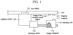
- FIG. 1 is a diagram for describing a relationship between a magnet 101 of a disc 100 installed on a turntable 121, a magnet 111 of a feeding unit 110, and an image obtainer 112, when an image of an analysis or test result object (hereinafter, abbreviated to an analysis result object) 102 of the disc 100 is to be obtained.
- an analysis result object hereinafter, abbreviated to an analysis result object
- FIG. 1 when the image of the analysis result object 102, installed on the disc 100, is to be obtained after completing an analysis or a test of the disc 100 installed on the turntable 121 of a rotation motor 120, the positioning of the disc 100 is fixed by a magnetic attraction between the magnet 101, which is installed below the disc 100, and by the magnet 111, which is installed on the feeding unit 110.
- the positioning of the disc 100 is a positioning where the image obtainer 112 is able to recognize the analysis result object 102. Accordingly, the magnet 101 and the magnet 111 have opposite polarities.
- a feeding motor 125 controls the feeding unit 110 to move along a radial direction of the disc 100.
- an image of the analysis result object 102 obtained by the image obtainer 112 does not have slope or alignment deviation.
- the positioning of the magnet 101 and the positioning of the magnet 111 may not correspond to or align with each other, such as shown in FIGS. 2B and 2C .
- an image of the analysis result object 102 obtained by the image obtainer 112 has slope deviation.
- the image of the analysis result object 102 obtained by the image obtainer 112 has slope deviation.
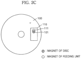
- FIGS. 2A through 2C are conceptual diagrams for describing a difference between the positionings of the magnet 101 of the disc 100 and the magnet 111 of the feeding unit 110, wherein a top surface of the disc 100 is shown.
- FIG. 2A illustrates a case when a difference does not exist between the magnets 101 and 111
- FIGS. 2B and 2C illustrate cases when an alignment difference exists between the magnets 101 and 111.
- FIG. 3 is a functional block diagram of an apparatus 300 for driving a disc 310, according to an embodiment.
- the apparatus 300 includes a rotation motor 301, a rotation axis 302, a turntable 303, a feeding unit 305 installed with a magnet 304, a feeding motor 306, an image obtainer 307, and a controller 308.
- a magnet 311 and an analysis or test result object (hereinafter, abbreviated to analysis result object) 312 are installed on the disc 310.
- the magnet 311 may be a permanent magnet.
- the analysis result object 312 may be a piece of reaction-paper or an assay site.
- the analysis result object 312 may show a result of analyzing or testing the disc 310.
- the disc 310 may be a non-optical bio disc or an optical bio disc. The disc 310 analyzes or tests a sample injected into the disc 310.
- the controller 308 controls the rotation motor 301 to rotate the disc 310 so that the disc 310 performs analysis or test.
- the rotation motor 301 may be a spindle motor.
- the controller 308 controls the rotation motor 301 to stop the rotating of the disc 310.
- the controller 308 fixes the positioning of the disc 310 to obtain an image of the analysis result object 312, which is installed on the disc 310, after the analysis or test.
- the controller 308 controls the feeding motor 306 to move the feeding unit 305 so that the positioning of the magnet 304 of the feeding unit 305 and the positioning of the magnet 311 of the disc 310 correspond to or align with each other along a radial direction of the disc.
- the feeding motor 306 may control the feeding unit 305 to move along a radial direction of the disc 310.
- the feeding unit 305 may be a slider or a sled. Since the feeding unit 305 may include a bio optical pickup module, the feeding unit 305 may be a bio optical pickup unit.
- the magnet 304 is oriented to have a polarity opposite to that of the magnet 311 facing the magnet 304, and is disposed in such a position that the analysis result object 312 installed on the disc 310, by a magnetic attraction with the magnet 311, is recognized by the image obtainer 307.
- the magnet 304 may be a permanent magnet.
- the controller 308 controls the feeding motor 306 to drive the feeding unit 305.
- the feeding motor 306 may be a slider motor or a sled motor.
- the image obtainer 307 includes an image sensor, a camera unit, or a camera module, and obtains an image of the analysis result object 312 of the disc 310. Accordingly, the image obtainer 307 may be installed on the feeding unit 305, but instead, may be fixed in a positioning independent from the feeding unit 305.
- the apparatus 300 may include a lighting unit (not shown) using a device such as a light emitting diode (LED) (not shown).
- the lighting unit may be disposed adjacent to the image obtainer 307. For example, the LED may be disposed adjacent to the image obtainer 307, or the lighting unit may be disposed on a case surface of the apparatus 300 facing the top of the disc 310.
- the image obtainer 307 may be a line image sensor that senses the amount of light on a pixel unit.
- the controller 308 may control the feeding motor 306 to minimize a radial alignment difference between positionings of the magnet 304 and the magnet 311, before the image obtainer 307 is to obtain an image of the analysis result object 312 and after fixing the positioning of the disc.
- the controller 308 may control the feeding motor 306 to move the feeding unit 305 in a direction from an outer circumference to an inner circumference of the disc 310 at least once.
- the controller 308 may control the feeding motor 306 to move the feeding unit 305 in a direction from an outer circumference to an inner circumference of the disc 310 once, and then further move the feeding unit 305 in a direction from the inner circumference to an outer circumference at least once.
- the controller 308 may control the feeding motor 306 to move the feeding unit 305 in a direction from an inner circumference to an outer circumference of the disc 310 once, and then in a direction from the outer circumference to an inner circumference of the disc 310 once.
- the controller 308 may control the feeding motor 306 to move the feeding unit 305 in a direction from an outer circumference to an inner circumference and in a direction from an inner circumference to an outer circumference a plurality of times.
- a difference between positionings of a magnet of a disc and a magnet of a feeding unit is minimized when obtaining an image of analysis or test result object of the disc, and thus slope deviation of the obtained image is minimized. Accordingly, an apparatus of driving a disc that has high reliability for an image analysis result can be provided.
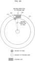
- FIGS. 4A and 4B are diagrams for describing a relationship between a moving direction of the feeding unit 305 and a moving direction of the disc 310.
- FIG. 4A illustrates a case where the disc 310 rotates counterclockwise as the magnet 311 of the disc 310 is affected by a magnetic force of the magnet 304 of the feeding unit 305, when the feeding unit 305 moves in a direction from an outer circumference to an inner circumference of the disc 310.
- FIG. 4B illustrates a case where the disc rotates clockwise as the magnet 311 is affected by the magnetic force of the magnet 304, when the feeding unit 305 moves in a direction from the inner circumference to the outer circumference of the disc 310.
- the controller 308 controls the feeding motor 306 to minimize the difference between positionings of the magnets 311 and 304 based on the moving direction of the feeding unit 305 and the rotation direction of the disc 310.
- the controller 308 controls the feeding motor 306 to move the feeding unit 305 at a speed that rotates the disc 310 as the magnet 311 of the disc 310 is affected by a magnetic force to the magnet 304 of the feeding unit 305.
- the controller 308 controls the image obtainer 307 to obtain an image of the analysis result object 312 of the disc 310.
- the obtained image may be output via an output unit (not shown) connected to the apparatus 300 of FIG. 3 .
- the output unit transmits or displays the obtained image, and may be an Internet interface unit, a computer system, or a display unit.
- An analysis result of the disc 310 is determined based on the image output via the output unit.
- the apparatus 300 having high reliability on an image analysis result can be provided.
- FIG. 5 is a flowchart illustrating a method of obtaining an image of a disc, according to an embodiment.
- the image of the disc is an analysis or test result image of the disc, and is obtained based on an analysis or test result object installed on the disc. The method will now be described with reference to FIGS. 3 and 5 .
- the controller 308 fixes a positioning of the disc 310 by using a first magnet and a second magnet.
- the first magnet is the magnet 311 of the disc 310 and the second magnet is the magnet 304 of the feeding unit 305.
- the positioning of the disc 310 is a positioning where the image obtainer 307 can recognize the analysis result object 312 installed on the disc 310.
- the controller 308 minimizes a difference between positionings of the magnets 311 and 304.
- the controller 308 may control the feeding motor 306 to move the feeding unit 305 in a direction from an outer circumference of the disc 310 to an inner circumference of the disc 310 at least once.
- the controller 308 may control the feeding motor 306 to move the feeding unit 305 in a direction from the outer circumference to the inner circumference once, and then in a direction from the inner circumference to the outer circumference at least once.
- the controller 308 may control the feeding motor 306 to move the feeding unit 305 in a direction from the outer circumference to the inner circumference and in a direction from the inner circumference to the outer circumference a plurality of times.
- the controller 308 controls the feeding motor 306 to move the feeding unit 305 at a speed that rotates the disc 310 as shown in FIGS. 4A and 4B as the magnet 311 is affected by magnetic force to the magnet 304.
- the controller 308 controls the image obtainer 307 to obtain an image of the analysis result object 312 of the disc 310 in operation 504.
- the image of the analysis result object 312 is an analysis result on the sample injected into the disc 310.
- operations 502 through 504 may be performed according to an image obtaining request of a user on the disc 310 that is completed the analysis or test on the sample.
- the embodiments can be implemented as a method, an apparatus, and a system.
- its component elements are code segments that execute necessary operations.
- Programs or code segments can be stored in processor readable media.
- the processor readable medium can be any medium that can store or transmit data. Examples of the processor readable medium include electronic circuits, semiconductor memory devices, ROMs, flash memories, erasable ROMs (EROMs), floppy discs, optical discs, hard discs, optical fibers, radio frequency (RF) networks, etc.
Landscapes
- Health & Medical Sciences (AREA)
- Chemical & Material Sciences (AREA)
- Life Sciences & Earth Sciences (AREA)
- Engineering & Computer Science (AREA)
- Analytical Chemistry (AREA)
- General Health & Medical Sciences (AREA)
- General Physics & Mathematics (AREA)
- Physics & Mathematics (AREA)
- Immunology (AREA)
- Biochemistry (AREA)
- Hematology (AREA)
- Pathology (AREA)
- Biomedical Technology (AREA)
- Molecular Biology (AREA)
- Urology & Nephrology (AREA)
- Food Science & Technology (AREA)
- Medicinal Chemistry (AREA)
- Chemical Kinetics & Catalysis (AREA)
- Clinical Laboratory Science (AREA)
- Dispersion Chemistry (AREA)
- Aviation & Aerospace Engineering (AREA)
- Radar, Positioning & Navigation (AREA)
- Remote Sensing (AREA)
- Automation & Control Theory (AREA)
- Biotechnology (AREA)
- Cell Biology (AREA)
- Microbiology (AREA)
- Testing Of Coins (AREA)
- Automatic Analysis And Handling Materials Therefor (AREA)
- Investigating Or Analysing Materials By Optical Means (AREA)
- Length Measuring Devices By Optical Means (AREA)
- Investigating, Analyzing Materials By Fluorescence Or Luminescence (AREA)
Description
- The inventive concept relates to obtaining an image of a disc, and more particularly, to a method of obtaining an image of an analysis or test result of a disc, and an apparatus for driving a disc, wherein the apparatus includes a disc and a feeding unit each having a magnet and the apparatus performs the method.
- A disc having a magnet may be a bio disc. A bio disc may be a digital bio disc on which a lab on a chip, which includes one of various diagnosis analyzing apparatuses, a nucleic acid hybrid analyzing apparatus, or an immunological verifying apparatus for a sample injected into the bio disc, is disposed.
- Such a bio disc (hereinafter, referred to as a disc) includes an analysis result object or a test result object, such as a piece of reaction-paper, that shows an analysis or test result. Magnets included in each of a disc and a feeding unit may be used to fix the positioning of the disc where an image obtainer, such as an image sensor or a camera unit, can recognize the analysis or test result object, when an image of the analysis or test result object is to be obtained.
- However, a difference between positionings of the magnets included in each of the disc and the feeding unit can occur.
- Document
WO 2007/073107 A1 discloses a bio memory disc where a lab-on-a-chip process system including an assay-diagnosis unit, a nucleic acid hybridization assay unit, or an immuno-assay unit and a semiconductor memory is disposed, and a bio memory disc drive apparatus including a controller for controlling and driving an optical disc including CD or DVD and the bio memory disc. - Additional aspects and/or advantages will be set forth in part in the description which follows and, in part, will be apparent from the description, or may be learned by practice of the invention.
- The inventive concept provides a method of obtaining an image of a disc as defined in
claim 1. - According to another aspect, there is provided an apparatus for driving a disc as defined in claim 4.
- These and/or other aspects and advantages will become apparent and more readily appreciated from the following description of the embodiments, taken in conjunction with the accompanying drawings of which:
-
FIG. 1 is a diagram for describing a relationship between a magnet of a disc installed on a turntable, a magnet of a feeding unit, and an image obtainer, when an analysis or test result object of the disc is obtained; -
FIGS. 2 A through 2C are conceptual diagrams for describing a difference between positionings of a magnet of a disc and a magnet of a feeding unit, viewed from a top surface of the disc; -
FIG. 3 is a functional block diagram of an apparatus for driving a disc, according to an embodiment; -
FIGS. 4A and4B are diagrams for describing a relationship between a moving direction of a feeding unit and a moving direction of a disc; and -
FIG. 5 is a flowchart illustrating a method of obtaining an image of a disc, according to an embodiment. - Reference will now be made in detail to the embodiments, examples of which are illustrated in the accompanying drawings, wherein like reference numerals refer to the like elements throughout. The embodiments are described below to explain the present invention by referring to the figures.
- Hereinafter, the inventive concept will be described in detail by explaining exemplary embodiments with reference to the attached drawings.
-
FIG. 1 is a diagram for describing a relationship between amagnet 101 of adisc 100 installed on aturntable 121, amagnet 111 of afeeding unit 110, and an image obtainer 112, when an image of an analysis or test result object (hereinafter, abbreviated to an analysis result object) 102 of thedisc 100 is to be obtained. Referring toFIG. 1 , when the image of theanalysis result object 102, installed on thedisc 100, is to be obtained after completing an analysis or a test of thedisc 100 installed on theturntable 121 of arotation motor 120, the positioning of thedisc 100 is fixed by a magnetic attraction between themagnet 101, which is installed below thedisc 100, and by themagnet 111, which is installed on thefeeding unit 110. Here, the positioning of thedisc 100 is a positioning where the image obtainer 112 is able to recognize theanalysis result object 102. Accordingly, themagnet 101 and themagnet 111 have opposite polarities. Afeeding motor 125 controls thefeeding unit 110 to move along a radial direction of thedisc 100. - When the positioning of the
magnet 101 of thedisc 100 and the positioning of themagnet 111 of thefeeding unit 110 correspond to each other as shown inFIG. 2A , an image of theanalysis result object 102 obtained by the image obtainer 112 does not have slope or alignment deviation. - However, since characteristics of the
rotation motor 120 and magnetic force between themagnet 101 and themagnet 111 are not always consistent, the positioning of themagnet 101 and the positioning of themagnet 111 may not correspond to or align with each other, such as shown inFIGS. 2B and2C . - When the positioning of the
magnet 101 and the positioning of themagnet 111 do not correspond to each other, an image of theanalysis result object 102 obtained by the image obtainer 112 has slope deviation. In other words, when the positioning of themagnet 101 differs from the positioning of themagnet 111, the image of theanalysis result object 102 obtained by theimage obtainer 112 has slope deviation. As such, when an image obtained by the image obtainer 112 has slope deviation, it is hard to obtain an accurate image of theanalysis result object 102. -
FIGS. 2A through 2C are conceptual diagrams for describing a difference between the positionings of themagnet 101 of thedisc 100 and themagnet 111 of thefeeding unit 110, wherein a top surface of thedisc 100 is shown.FIG. 2A illustrates a case when a difference does not exist between themagnets FIGS. 2B and2C illustrate cases when an alignment difference exists between themagnets -
FIG. 3 is a functional block diagram of anapparatus 300 for driving adisc 310, according to an embodiment. Referring toFIG. 3 , theapparatus 300 includes arotation motor 301, arotation axis 302, aturntable 303, afeeding unit 305 installed with amagnet 304, afeeding motor 306, an image obtainer 307, and acontroller 308. - A
magnet 311 and an analysis or test result object (hereinafter, abbreviated to analysis result object) 312 are installed on thedisc 310. Themagnet 311 may be a permanent magnet. Theanalysis result object 312 may be a piece of reaction-paper or an assay site. Theanalysis result object 312 may show a result of analyzing or testing thedisc 310. Thedisc 310 may be a non-optical bio disc or an optical bio disc. Thedisc 310 analyzes or tests a sample injected into thedisc 310. - When the
disc 310 is mounted on theturntable 303, which is installed on therotation axis 302, thecontroller 308 controls therotation motor 301 to rotate thedisc 310 so that thedisc 310 performs analysis or test. Therotation motor 301 may be a spindle motor. - After analyzing or testing by the
disc 310, thecontroller 308 controls therotation motor 301 to stop the rotating of thedisc 310. Here, thecontroller 308 fixes the positioning of thedisc 310 to obtain an image of theanalysis result object 312, which is installed on thedisc 310, after the analysis or test. To fix the positioning of thedisc 310, thecontroller 308 controls thefeeding motor 306 to move thefeeding unit 305 so that the positioning of themagnet 304 of thefeeding unit 305 and the positioning of themagnet 311 of thedisc 310 correspond to or align with each other along a radial direction of the disc. - The
feeding motor 306 may control thefeeding unit 305 to move along a radial direction of thedisc 310. Thefeeding unit 305 may be a slider or a sled. Since thefeeding unit 305 may include a bio optical pickup module, thefeeding unit 305 may be a bio optical pickup unit. Themagnet 304 is oriented to have a polarity opposite to that of themagnet 311 facing themagnet 304, and is disposed in such a position that theanalysis result object 312 installed on thedisc 310, by a magnetic attraction with themagnet 311, is recognized by the image obtainer 307. Themagnet 304 may be a permanent magnet. - The
controller 308 controls thefeeding motor 306 to drive thefeeding unit 305. Thefeeding motor 306 may be a slider motor or a sled motor. - The image obtainer 307 includes an image sensor, a camera unit, or a camera module, and obtains an image of the
analysis result object 312 of thedisc 310. Accordingly, theimage obtainer 307 may be installed on thefeeding unit 305, but instead, may be fixed in a positioning independent from thefeeding unit 305. In order for theimage obtainer 307 to obtain an image of theanalysis result object 312 of thedisc 310, theapparatus 300 may include a lighting unit (not shown) using a device such as a light emitting diode (LED) (not shown). The lighting unit may be disposed adjacent to theimage obtainer 307. For example, the LED may be disposed adjacent to theimage obtainer 307, or the lighting unit may be disposed on a case surface of theapparatus 300 facing the top of thedisc 310. - When the
image obtainer 307 includes an image sensor, theimage obtainer 307 may be a line image sensor that senses the amount of light on a pixel unit. - The
controller 308 may control the feedingmotor 306 to minimize a radial alignment difference between positionings of themagnet 304 and themagnet 311, before theimage obtainer 307 is to obtain an image of theanalysis result object 312 and after fixing the positioning of the disc. - In other words, in order to minimize the difference, the
controller 308 may control the feedingmotor 306 to move thefeeding unit 305 in a direction from an outer circumference to an inner circumference of thedisc 310 at least once. Alternatively, thecontroller 308 may control the feedingmotor 306 to move thefeeding unit 305 in a direction from an outer circumference to an inner circumference of thedisc 310 once, and then further move thefeeding unit 305 in a direction from the inner circumference to an outer circumference at least once. Alternatively, thecontroller 308 may control the feedingmotor 306 to move thefeeding unit 305 in a direction from an inner circumference to an outer circumference of thedisc 310 once, and then in a direction from the outer circumference to an inner circumference of thedisc 310 once. - Alternatively, the
controller 308 may control the feedingmotor 306 to move thefeeding unit 305 in a direction from an outer circumference to an inner circumference and in a direction from an inner circumference to an outer circumference a plurality of times. - As described above, a difference between positionings of a magnet of a disc and a magnet of a feeding unit is minimized when obtaining an image of analysis or test result object of the disc, and thus slope deviation of the obtained image is minimized. Accordingly, an apparatus of driving a disc that has high reliability for an image analysis result can be provided.
-
FIGS. 4A and4B are diagrams for describing a relationship between a moving direction of thefeeding unit 305 and a moving direction of thedisc 310.FIG. 4A illustrates a case where thedisc 310 rotates counterclockwise as themagnet 311 of thedisc 310 is affected by a magnetic force of themagnet 304 of thefeeding unit 305, when thefeeding unit 305 moves in a direction from an outer circumference to an inner circumference of thedisc 310.FIG. 4B illustrates a case where the disc rotates clockwise as themagnet 311 is affected by the magnetic force of themagnet 304, when thefeeding unit 305 moves in a direction from the inner circumference to the outer circumference of thedisc 310. Thecontroller 308 controls the feedingmotor 306 to minimize the difference between positionings of themagnets feeding unit 305 and the rotation direction of thedisc 310. Here, thecontroller 308 controls the feedingmotor 306 to move thefeeding unit 305 at a speed that rotates thedisc 310 as themagnet 311 of thedisc 310 is affected by a magnetic force to themagnet 304 of thefeeding unit 305. - After minimizing the difference between the positionings of the
magnets controller 308 controls theimage obtainer 307 to obtain an image of theanalysis result object 312 of thedisc 310. The obtained image may be output via an output unit (not shown) connected to theapparatus 300 ofFIG. 3 . The output unit transmits or displays the obtained image, and may be an Internet interface unit, a computer system, or a display unit. An analysis result of thedisc 310 is determined based on the image output via the output unit. - As described above, by minimizing the difference between positionings of the
magnets analysis result object 312 of thedisc 310, slope deviation of the image of theanalysis result object 312 is minimized. Accordingly, theapparatus 300 having high reliability on an image analysis result can be provided. -
FIG. 5 is a flowchart illustrating a method of obtaining an image of a disc, according to an embodiment. The image of the disc is an analysis or test result image of the disc, and is obtained based on an analysis or test result object installed on the disc. The method will now be described with reference toFIGS. 3 and5 . - Referring to
FIG. 5 , it is determined whether an analysis or test on a sample by a disc is completed inoperation 501. The sample is a sample injected into thedisc 310. If the analysis or test by thedisc 310 is completed, thecontroller 308 fixes a positioning of thedisc 310 by using a first magnet and a second magnet. Here, the first magnet is themagnet 311 of thedisc 310 and the second magnet is themagnet 304 of thefeeding unit 305. The positioning of thedisc 310 is a positioning where theimage obtainer 307 can recognize theanalysis result object 312 installed on thedisc 310. - Next, in
operation 503, thecontroller 308 minimizes a difference between positionings of themagnets controller 308 may control the feedingmotor 306 to move thefeeding unit 305 in a direction from an outer circumference of thedisc 310 to an inner circumference of thedisc 310 at least once. Alternatively, thecontroller 308 may control the feedingmotor 306 to move thefeeding unit 305 in a direction from the outer circumference to the inner circumference once, and then in a direction from the inner circumference to the outer circumference at least once. Alternatively, thecontroller 308 may control the feedingmotor 306 to move thefeeding unit 305 in a direction from the outer circumference to the inner circumference and in a direction from the inner circumference to the outer circumference a plurality of times. Here, thecontroller 308 controls the feedingmotor 306 to move thefeeding unit 305 at a speed that rotates thedisc 310 as shown inFIGS. 4A and4B as themagnet 311 is affected by magnetic force to themagnet 304. - After minimizing the difference between positionings of the
magnets controller 308 controls theimage obtainer 307 to obtain an image of theanalysis result object 312 of thedisc 310 inoperation 504. The image of theanalysis result object 312 is an analysis result on the sample injected into thedisc 310. - In the method,
operations 502 through 504 may be performed according to an image obtaining request of a user on thedisc 310 that is completed the analysis or test on the sample. - The embodiments can be implemented as a method, an apparatus, and a system. When the embodiments are implemented in software, its component elements are code segments that execute necessary operations. Programs or code segments can be stored in processor readable media. The processor readable medium can be any medium that can store or transmit data. Examples of the processor readable medium include electronic circuits, semiconductor memory devices, ROMs, flash memories, erasable ROMs (EROMs), floppy discs, optical discs, hard discs, optical fibers, radio frequency (RF) networks, etc.
Claims (5)
- A method for obtaining an image of a test result object (102, 312) on a disc (100, 310), the method comprising:fixing (502) a positioning of a disc (100, 310) by using magnetic attraction creating an alignment between a first magnet (101, 311) installed on the disc (100, 310) and a second magnet (111, 304) installed on a feeding unit (110, 305),decreasing or minimizing (503) a difference between the positioning of the first (101, 311) and second (111, 304) magnets, andobtaining (504) an image of the test result object (102, 312) on the disc (100, 310),wherein the step of the minimizing the difference comprises:moving the feeding unit (110, 305) in a direction from an outer circumference of the disc (100, 310) to an inner circumference of the disc (100, 310) at least once or in a direction from the inner circumference to the outer circumference at least once,such that the disc (100, 301) rotates as the first magnet (101, 311) is affected by magnetic force of the second magnet (111, 304).
- The method of claim 1, wherein, in the minimizing of the difference, the difference between the positioning is minimized by moving the feeding unit (110, 305) in a direction from an outer circumference of the disc (100, 310) to an inner circumference of the disc (100, 310) and in a direction from the inner circumference to the outer circumference a plurality of times.
- The method of claim 1, wherein the difference comprises a radial alignment difference and the radial alignment difference is minimized.
- An apparatus (300) for driving a disc (100, 310), the apparatus (300) comprising:a turntable (121, 303) on which the disc (100, 310) having a first magnet (101, 311) is attached,a rotation motor (120, 301) to rotate the turntable (121, 303),a feeding unit (110, 305) having a second magnet (111, 304) attached thereon,a feeding motor (125, 306) that transfers the feeding unit (110, 305),an image obtainer (112, 307) that obtains an image of a test result object (102, 312) of the disc (100, 310); anda controller (308) that controls the feeding motor (125, 306) to reduce misalignment between the first (101, 311) and the second (111, 304) magnets, when fixing a positioning of the disc (100, 310) using magnetic attraction between the first (101, 311) and second (111, 304) magnets, after testing on a sample by the disc (100, 310), wherein the sample is a sample injected into the disc (100, 310),wherein the controller (308) minimizes the difference by controlling the feeding motor (125, 306) to:move the feeding unit (110, 305) in a direction from an outer circumference of the disc (100, 310) to an inner circumference of the disc (100, 310) at least once or in a direction from the inner circumference to the outer circumference at least once,such that the disc (100, 301) rotates as the first magnet (101, 311) is affected by magnetic force of the second magnet (111, 304).
- The apparatus (300) of claim 4, wherein the controller (308) controls the feeding motor (125, 306) so as to minimize the difference by moving the feeding unit (110, 305) in a direction from an outer circumference of the disc (100, 310) to an inner circumference of the disc (100, 310) and in a direction from the inner circumference to the outer circumference a plurality of times.
Applications Claiming Priority (1)
| Application Number | Priority Date | Filing Date | Title |
|---|---|---|---|
| KR1020090028256A KR101579162B1 (en) | 2009-04-01 | 2009-04-01 | Disk image acquisition method and disk drive |
Publications (3)
| Publication Number | Publication Date |
|---|---|
| EP2237045A2 EP2237045A2 (en) | 2010-10-06 |
| EP2237045A3 EP2237045A3 (en) | 2015-07-29 |
| EP2237045B1 true EP2237045B1 (en) | 2023-05-24 |
Family
ID=42502535
Family Applications (1)
| Application Number | Title | Priority Date | Filing Date |
|---|---|---|---|
| EP10154257.9A Active EP2237045B1 (en) | 2009-04-01 | 2010-02-22 | Method of obtaining image of disc and apparatus for driving disc |
Country Status (5)
| Country | Link |
|---|---|
| US (1) | US8456127B2 (en) |
| EP (1) | EP2237045B1 (en) |
| JP (1) | JP2010243488A (en) |
| KR (1) | KR101579162B1 (en) |
| ES (1) | ES2955344T3 (en) |
Families Citing this family (5)
| Publication number | Priority date | Publication date | Assignee | Title |
|---|---|---|---|---|
| KR101339923B1 (en) * | 2011-11-03 | 2013-12-10 | 삼성전자주식회사 | Disk and test apparatus including the disk |
| KR20140009606A (en) * | 2012-07-11 | 2014-01-23 | 삼성전자주식회사 | Test device and control method thereof |
| KR20140009607A (en) * | 2012-07-11 | 2014-01-23 | 삼성전자주식회사 | Test device and control method thereof |
| JP2017534859A (en) * | 2014-09-29 | 2017-11-24 | バイオサーフィット、 ソシエダッド アノニマ | Positioning mechanism |
| DE102015005134A1 (en) * | 2015-04-22 | 2016-10-27 | Testo Ag | Cytometer unit, cytometry method, rotatable sample carrier and corresponding use thereof |
Family Cites Families (17)
| Publication number | Priority date | Publication date | Assignee | Title |
|---|---|---|---|---|
| JPS6143794U (en) * | 1984-08-24 | 1986-03-22 | 株式会社 ユニカム | Oscillating actuator using permanent magnets |
| US5272092A (en) * | 1987-11-12 | 1993-12-21 | Hitachi, Ltd. | Method for analyzing a reaction solution |
| JPH0619359B2 (en) * | 1989-04-11 | 1994-03-16 | 出光石油化学株式会社 | Liquid sample analyzer |
| JPH04305879A (en) * | 1990-09-12 | 1992-10-28 | Fuji Electric Co Ltd | Device for binding moving body to operate head of disk storage device |
| AU2002219979A1 (en) | 2000-12-01 | 2002-06-11 | Burstein Technologies, Inc. | Apparatus and methods for separating components of particulate suspension |
| KR100631507B1 (en) | 2000-12-13 | 2006-10-09 | 엘지전자 주식회사 | Disc sagging prevention device of disc player |
| CN1656369A (en) * | 2002-05-30 | 2005-08-17 | 松下电器产业株式会社 | Analysis device and analysis disc used for the same |
| US7275303B1 (en) * | 2003-03-06 | 2007-10-02 | Maxtor Corporation | Method for making a disc drive |
| US6943478B2 (en) * | 2003-11-14 | 2005-09-13 | Dura-Trac Motors, Inc. | Brushless permanent magnet wheel motor with variable axial rotor/stator alignment |
| US7990819B2 (en) * | 2004-04-22 | 2011-08-02 | Panasonic Corporation | Optical head apparatus and optical information apparatus |
| EP1888778B1 (en) * | 2005-05-06 | 2012-11-14 | Samsung Electronics Co., Ltd. | Digital bio disc(dbd), dbd driver apparatus, and assay method using the same |
| US9279818B2 (en) * | 2005-06-28 | 2016-03-08 | Samsung Electronics Co., Ltd. | Bio drive apparatus, and assay method using the same |
| US8951779B2 (en) * | 2005-12-21 | 2015-02-10 | Samsung Electronics Co., Ltd. | Bio memory disc and bio memory disc drive apparatus, and assay method using the same |
| WO2007106013A1 (en) * | 2006-03-13 | 2007-09-20 | Gyros Patent Ab | Enhanced magnetic particle steering |
| EP1939629A3 (en) | 2006-08-11 | 2011-03-09 | Samsung Electronics Co., Ltd. | Centrifugal Force Based Magnet Position Control Device and Disk-Shaped Micro Fluidic System |
| KR101343034B1 (en) * | 2006-09-05 | 2013-12-18 | 삼성전자 주식회사 | Centrifugal microfluidic device for target protein detection and microfluidic system comprising the same |
| US8273310B2 (en) * | 2006-09-05 | 2012-09-25 | Samsung Electronics Co., Ltd. | Centrifugal force-based microfluidic device for nucleic acid extraction and microfluidic system including the microfluidic device |
-
2009
- 2009-04-01 KR KR1020090028256A patent/KR101579162B1/en active Active
-
2010
- 2010-02-18 US US12/707,741 patent/US8456127B2/en active Active
- 2010-02-22 ES ES10154257T patent/ES2955344T3/en active Active
- 2010-02-22 EP EP10154257.9A patent/EP2237045B1/en active Active
- 2010-03-29 JP JP2010075447A patent/JP2010243488A/en active Pending
Also Published As
| Publication number | Publication date |
|---|---|
| KR101579162B1 (en) | 2015-12-21 |
| US8456127B2 (en) | 2013-06-04 |
| JP2010243488A (en) | 2010-10-28 |
| US20100254238A1 (en) | 2010-10-07 |
| EP2237045A2 (en) | 2010-10-06 |
| ES2955344T3 (en) | 2023-11-30 |
| KR20100109799A (en) | 2010-10-11 |
| EP2237045A3 (en) | 2015-07-29 |
Similar Documents
| Publication | Publication Date | Title |
|---|---|---|
| US8456127B2 (en) | Method of obtaining image of disc and apparatus for driving disc | |
| CN1273983C (en) | Data storage device for background verifying record medium or detecting data of write-in medium | |
| CN101726986B (en) | Assembling and testing device and method thereof | |
| CN102105936B (en) | Vehicle system | |
| CN107398899A (en) | Wireless signal strength positioning guidance system and method | |
| CN106997233B (en) | Providing access from outside the multicore processor SoC to configure voltages independently | |
| US20080073435A1 (en) | Code scanning device and code scanning method using the same | |
| CN102681132B (en) | For regulating equipment and the method for the position of optical element | |
| US9071173B2 (en) | Motor control device, and optical scanning device, image forming device and printed circuit board including the same | |
| CN1848094A (en) | Apparatus and method for testing computer system | |
| US9864006B1 (en) | Generating a unique die identifier for an electronic chip | |
| KR20230173464A (en) | System for testing camera module and operating methode thereof | |
| CN217846344U (en) | Automatic loading device for biological chip | |
| US8490122B2 (en) | Disc chucking method and disc driving apparatus | |
| JP2010061767A (en) | In-vehicle device | |
| CN101128876A (en) | Optical Data Media Detection Technology | |
| CN111386466B (en) | Measuring system, method and non-volatile data carrier for a rotary milking parlor with a movable platform | |
| CN114505861A (en) | Direction compensation method and system based on pneumatic clamping jaw control | |
| CN113008131A (en) | Motor position detection system and motor | |
| JP2005109376A (en) | Transparent substrate alignment method | |
| CN103514905A (en) | Position control method and system of optical pickup head of optical drive | |
| JPH1012709A (en) | Circular substrate positioning device | |
| JP7611285B2 (en) | Wireless communication system and wireless power supply system | |
| US20050172036A1 (en) | Method for transmitting data in a multi-chip system | |
| CN110161262B (en) | Rotating device and reagent tray |
Legal Events
| Date | Code | Title | Description |
|---|---|---|---|
| PUAI | Public reference made under article 153(3) epc to a published international application that has entered the european phase |
Free format text: ORIGINAL CODE: 0009012 |
|
| AK | Designated contracting states |
Kind code of ref document: A2 Designated state(s): AT BE BG CH CY CZ DE DK EE ES FI FR GB GR HR HU IE IS IT LI LT LU LV MC MK MT NL NO PL PT RO SE SI SK SM TR |
|
| AX | Request for extension of the european patent |
Extension state: AL BA RS |
|
| RAP1 | Party data changed (applicant data changed or rights of an application transferred) |
Owner name: SAMSUNG ELECTRONICS CO., LTD. |
|
| PUAL | Search report despatched |
Free format text: ORIGINAL CODE: 0009013 |
|
| AK | Designated contracting states |
Kind code of ref document: A3 Designated state(s): AT BE BG CH CY CZ DE DK EE ES FI FR GB GR HR HU IE IS IT LI LT LU LV MC MK MT NL NO PL PT RO SE SI SK SM TR |
|
| AX | Request for extension of the european patent |
Extension state: AL BA RS |
|
| RIC1 | Information provided on ipc code assigned before grant |
Ipc: G11B 17/00 20060101ALI20150623BHEP Ipc: G01N 33/487 20060101ALI20150623BHEP Ipc: G01N 35/00 20060101AFI20150623BHEP |
|
| 17P | Request for examination filed |
Effective date: 20160129 |
|
| RBV | Designated contracting states (corrected) |
Designated state(s): AT BE BG CH CY CZ DE DK EE ES FI FR GB GR HR HU IE IS IT LI LT LU LV MC MK MT NL NO PL PT RO SE SI SK SM TR |
|
| RAP1 | Party data changed (applicant data changed or rights of an application transferred) |
Owner name: NEXUS DX, INC. |
|
| STAA | Information on the status of an ep patent application or granted ep patent |
Free format text: STATUS: EXAMINATION IS IN PROGRESS |
|
| 17Q | First examination report despatched |
Effective date: 20210510 |
|
| GRAP | Despatch of communication of intention to grant a patent |
Free format text: ORIGINAL CODE: EPIDOSNIGR1 |
|
| STAA | Information on the status of an ep patent application or granted ep patent |
Free format text: STATUS: GRANT OF PATENT IS INTENDED |
|
| INTG | Intention to grant announced |
Effective date: 20220630 |
|
| GRAJ | Information related to disapproval of communication of intention to grant by the applicant or resumption of examination proceedings by the epo deleted |
Free format text: ORIGINAL CODE: EPIDOSDIGR1 |
|
| STAA | Information on the status of an ep patent application or granted ep patent |
Free format text: STATUS: EXAMINATION IS IN PROGRESS |
|
| GRAP | Despatch of communication of intention to grant a patent |
Free format text: ORIGINAL CODE: EPIDOSNIGR1 |
|
| STAA | Information on the status of an ep patent application or granted ep patent |
Free format text: STATUS: GRANT OF PATENT IS INTENDED |
|
| INTC | Intention to grant announced (deleted) | ||
| INTG | Intention to grant announced |
Effective date: 20221128 |
|
| GRAS | Grant fee paid |
Free format text: ORIGINAL CODE: EPIDOSNIGR3 |
|
| GRAA | (expected) grant |
Free format text: ORIGINAL CODE: 0009210 |
|
| STAA | Information on the status of an ep patent application or granted ep patent |
Free format text: STATUS: THE PATENT HAS BEEN GRANTED |
|
| AK | Designated contracting states |
Kind code of ref document: B1 Designated state(s): AT BE BG CH CY CZ DE DK EE ES FI FR GB GR HR HU IE IS IT LI LT LU LV MC MK MT NL NO PL PT RO SE SI SK SM TR |
|
| REG | Reference to a national code |
Ref country code: GB Ref legal event code: FG4D |
|
| REG | Reference to a national code |
Ref country code: CH Ref legal event code: EP |
|
| REG | Reference to a national code |
Ref country code: DE Ref legal event code: R096 Ref document number: 602010068811 Country of ref document: DE |
|
| REG | Reference to a national code |
Ref country code: AT Ref legal event code: REF Ref document number: 1569819 Country of ref document: AT Kind code of ref document: T Effective date: 20230615 |
|
| REG | Reference to a national code |
Ref country code: IE Ref legal event code: FG4D |
|
| P01 | Opt-out of the competence of the unified patent court (upc) registered |
Effective date: 20230530 |
|
| REG | Reference to a national code |
Ref country code: LT Ref legal event code: MG9D |
|
| REG | Reference to a national code |
Ref country code: NL Ref legal event code: MP Effective date: 20230524 |
|
| REG | Reference to a national code |
Ref country code: AT Ref legal event code: MK05 Ref document number: 1569819 Country of ref document: AT Kind code of ref document: T Effective date: 20230524 |
|
| PG25 | Lapsed in a contracting state [announced via postgrant information from national office to epo] |
Ref country code: SE Free format text: LAPSE BECAUSE OF FAILURE TO SUBMIT A TRANSLATION OF THE DESCRIPTION OR TO PAY THE FEE WITHIN THE PRESCRIBED TIME-LIMIT Effective date: 20230524 Ref country code: PT Free format text: LAPSE BECAUSE OF FAILURE TO SUBMIT A TRANSLATION OF THE DESCRIPTION OR TO PAY THE FEE WITHIN THE PRESCRIBED TIME-LIMIT Effective date: 20230925 Ref country code: NO Free format text: LAPSE BECAUSE OF FAILURE TO SUBMIT A TRANSLATION OF THE DESCRIPTION OR TO PAY THE FEE WITHIN THE PRESCRIBED TIME-LIMIT Effective date: 20230824 Ref country code: NL Free format text: LAPSE BECAUSE OF FAILURE TO SUBMIT A TRANSLATION OF THE DESCRIPTION OR TO PAY THE FEE WITHIN THE PRESCRIBED TIME-LIMIT Effective date: 20230524 Ref country code: AT Free format text: LAPSE BECAUSE OF FAILURE TO SUBMIT A TRANSLATION OF THE DESCRIPTION OR TO PAY THE FEE WITHIN THE PRESCRIBED TIME-LIMIT Effective date: 20230524 |
|
| PG25 | Lapsed in a contracting state [announced via postgrant information from national office to epo] |
Ref country code: PL Free format text: LAPSE BECAUSE OF FAILURE TO SUBMIT A TRANSLATION OF THE DESCRIPTION OR TO PAY THE FEE WITHIN THE PRESCRIBED TIME-LIMIT Effective date: 20230524 Ref country code: LV Free format text: LAPSE BECAUSE OF FAILURE TO SUBMIT A TRANSLATION OF THE DESCRIPTION OR TO PAY THE FEE WITHIN THE PRESCRIBED TIME-LIMIT Effective date: 20230524 Ref country code: LT Free format text: LAPSE BECAUSE OF FAILURE TO SUBMIT A TRANSLATION OF THE DESCRIPTION OR TO PAY THE FEE WITHIN THE PRESCRIBED TIME-LIMIT Effective date: 20230524 Ref country code: IS Free format text: LAPSE BECAUSE OF FAILURE TO SUBMIT A TRANSLATION OF THE DESCRIPTION OR TO PAY THE FEE WITHIN THE PRESCRIBED TIME-LIMIT Effective date: 20230924 Ref country code: HR Free format text: LAPSE BECAUSE OF FAILURE TO SUBMIT A TRANSLATION OF THE DESCRIPTION OR TO PAY THE FEE WITHIN THE PRESCRIBED TIME-LIMIT Effective date: 20230524 Ref country code: GR Free format text: LAPSE BECAUSE OF FAILURE TO SUBMIT A TRANSLATION OF THE DESCRIPTION OR TO PAY THE FEE WITHIN THE PRESCRIBED TIME-LIMIT Effective date: 20230825 |
|
| REG | Reference to a national code |
Ref country code: ES Ref legal event code: FG2A Ref document number: 2955344 Country of ref document: ES Kind code of ref document: T3 Effective date: 20231130 |
|
| PG25 | Lapsed in a contracting state [announced via postgrant information from national office to epo] |
Ref country code: FI Free format text: LAPSE BECAUSE OF FAILURE TO SUBMIT A TRANSLATION OF THE DESCRIPTION OR TO PAY THE FEE WITHIN THE PRESCRIBED TIME-LIMIT Effective date: 20230524 |
|
| PG25 | Lapsed in a contracting state [announced via postgrant information from national office to epo] |
Ref country code: SK Free format text: LAPSE BECAUSE OF FAILURE TO SUBMIT A TRANSLATION OF THE DESCRIPTION OR TO PAY THE FEE WITHIN THE PRESCRIBED TIME-LIMIT Effective date: 20230524 |
|
| PG25 | Lapsed in a contracting state [announced via postgrant information from national office to epo] |
Ref country code: SM Free format text: LAPSE BECAUSE OF FAILURE TO SUBMIT A TRANSLATION OF THE DESCRIPTION OR TO PAY THE FEE WITHIN THE PRESCRIBED TIME-LIMIT Effective date: 20230524 Ref country code: SK Free format text: LAPSE BECAUSE OF FAILURE TO SUBMIT A TRANSLATION OF THE DESCRIPTION OR TO PAY THE FEE WITHIN THE PRESCRIBED TIME-LIMIT Effective date: 20230524 Ref country code: RO Free format text: LAPSE BECAUSE OF FAILURE TO SUBMIT A TRANSLATION OF THE DESCRIPTION OR TO PAY THE FEE WITHIN THE PRESCRIBED TIME-LIMIT Effective date: 20230524 Ref country code: EE Free format text: LAPSE BECAUSE OF FAILURE TO SUBMIT A TRANSLATION OF THE DESCRIPTION OR TO PAY THE FEE WITHIN THE PRESCRIBED TIME-LIMIT Effective date: 20230524 Ref country code: DK Free format text: LAPSE BECAUSE OF FAILURE TO SUBMIT A TRANSLATION OF THE DESCRIPTION OR TO PAY THE FEE WITHIN THE PRESCRIBED TIME-LIMIT Effective date: 20230524 Ref country code: CZ Free format text: LAPSE BECAUSE OF FAILURE TO SUBMIT A TRANSLATION OF THE DESCRIPTION OR TO PAY THE FEE WITHIN THE PRESCRIBED TIME-LIMIT Effective date: 20230524 |
|
| REG | Reference to a national code |
Ref country code: DE Ref legal event code: R097 Ref document number: 602010068811 Country of ref document: DE |
|
| PLBE | No opposition filed within time limit |
Free format text: ORIGINAL CODE: 0009261 |
|
| STAA | Information on the status of an ep patent application or granted ep patent |
Free format text: STATUS: NO OPPOSITION FILED WITHIN TIME LIMIT |
|
| 26N | No opposition filed |
Effective date: 20240227 |
|
| PG25 | Lapsed in a contracting state [announced via postgrant information from national office to epo] |
Ref country code: SI Free format text: LAPSE BECAUSE OF FAILURE TO SUBMIT A TRANSLATION OF THE DESCRIPTION OR TO PAY THE FEE WITHIN THE PRESCRIBED TIME-LIMIT Effective date: 20230524 |
|
| PG25 | Lapsed in a contracting state [announced via postgrant information from national office to epo] |
Ref country code: SI Free format text: LAPSE BECAUSE OF FAILURE TO SUBMIT A TRANSLATION OF THE DESCRIPTION OR TO PAY THE FEE WITHIN THE PRESCRIBED TIME-LIMIT Effective date: 20230524 |
|
| PGFP | Annual fee paid to national office [announced via postgrant information from national office to epo] |
Ref country code: GB Payment date: 20240418 Year of fee payment: 15 |
|
| PGFP | Annual fee paid to national office [announced via postgrant information from national office to epo] |
Ref country code: DE Payment date: 20240419 Year of fee payment: 15 |
|
| PGFP | Annual fee paid to national office [announced via postgrant information from national office to epo] |
Ref country code: ES Payment date: 20240429 Year of fee payment: 15 |
|
| PGFP | Annual fee paid to national office [announced via postgrant information from national office to epo] |
Ref country code: IT Payment date: 20240424 Year of fee payment: 15 Ref country code: FR Payment date: 20240422 Year of fee payment: 15 |
|
| PG25 | Lapsed in a contracting state [announced via postgrant information from national office to epo] |
Ref country code: MC Free format text: LAPSE BECAUSE OF FAILURE TO SUBMIT A TRANSLATION OF THE DESCRIPTION OR TO PAY THE FEE WITHIN THE PRESCRIBED TIME-LIMIT Effective date: 20230524 |
|
| REG | Reference to a national code |
Ref country code: CH Ref legal event code: PL |
|
| PG25 | Lapsed in a contracting state [announced via postgrant information from national office to epo] |
Ref country code: LU Free format text: LAPSE BECAUSE OF NON-PAYMENT OF DUE FEES Effective date: 20240222 |
|
| PG25 | Lapsed in a contracting state [announced via postgrant information from national office to epo] |
Ref country code: CH Free format text: LAPSE BECAUSE OF NON-PAYMENT OF DUE FEES Effective date: 20240229 |
|
| PG25 | Lapsed in a contracting state [announced via postgrant information from national office to epo] |
Ref country code: LU Free format text: LAPSE BECAUSE OF NON-PAYMENT OF DUE FEES Effective date: 20240222 Ref country code: CH Free format text: LAPSE BECAUSE OF NON-PAYMENT OF DUE FEES Effective date: 20240229 |
|
| PG25 | Lapsed in a contracting state [announced via postgrant information from national office to epo] |
Ref country code: BG Free format text: LAPSE BECAUSE OF FAILURE TO SUBMIT A TRANSLATION OF THE DESCRIPTION OR TO PAY THE FEE WITHIN THE PRESCRIBED TIME-LIMIT Effective date: 20230524 |
|
| PG25 | Lapsed in a contracting state [announced via postgrant information from national office to epo] |
Ref country code: BG Free format text: LAPSE BECAUSE OF FAILURE TO SUBMIT A TRANSLATION OF THE DESCRIPTION OR TO PAY THE FEE WITHIN THE PRESCRIBED TIME-LIMIT Effective date: 20230524 |
|
| REG | Reference to a national code |
Ref country code: BE Ref legal event code: MM Effective date: 20240229 |
|
| PG25 | Lapsed in a contracting state [announced via postgrant information from national office to epo] |
Ref country code: BE Free format text: LAPSE BECAUSE OF NON-PAYMENT OF DUE FEES Effective date: 20240229 |
|
| PG25 | Lapsed in a contracting state [announced via postgrant information from national office to epo] |
Ref country code: IE Free format text: LAPSE BECAUSE OF NON-PAYMENT OF DUE FEES Effective date: 20240222 |
|
| PG25 | Lapsed in a contracting state [announced via postgrant information from national office to epo] |
Ref country code: IE Free format text: LAPSE BECAUSE OF NON-PAYMENT OF DUE FEES Effective date: 20240222 Ref country code: BE Free format text: LAPSE BECAUSE OF NON-PAYMENT OF DUE FEES Effective date: 20240229 |
|
| PG25 | Lapsed in a contracting state [announced via postgrant information from national office to epo] |
Ref country code: CY Free format text: LAPSE BECAUSE OF FAILURE TO SUBMIT A TRANSLATION OF THE DESCRIPTION OR TO PAY THE FEE WITHIN THE PRESCRIBED TIME-LIMIT; INVALID AB INITIO Effective date: 20100222 |
|
| REG | Reference to a national code |
Ref country code: DE Ref legal event code: R119 Ref document number: 602010068811 Country of ref document: DE |
|
| PG25 | Lapsed in a contracting state [announced via postgrant information from national office to epo] |
Ref country code: HU Free format text: LAPSE BECAUSE OF FAILURE TO SUBMIT A TRANSLATION OF THE DESCRIPTION OR TO PAY THE FEE WITHIN THE PRESCRIBED TIME-LIMIT; INVALID AB INITIO Effective date: 20100222 |
|
| GBPC | Gb: european patent ceased through non-payment of renewal fee |
Effective date: 20250222 |
|
| PG25 | Lapsed in a contracting state [announced via postgrant information from national office to epo] |
Ref country code: TR Free format text: LAPSE BECAUSE OF FAILURE TO SUBMIT A TRANSLATION OF THE DESCRIPTION OR TO PAY THE FEE WITHIN THE PRESCRIBED TIME-LIMIT Effective date: 20230524 |
|
| PG25 | Lapsed in a contracting state [announced via postgrant information from national office to epo] |
Ref country code: DE Free format text: LAPSE BECAUSE OF NON-PAYMENT OF DUE FEES Effective date: 20250902 |
|
| PG25 | Lapsed in a contracting state [announced via postgrant information from national office to epo] |
Ref country code: GB Free format text: LAPSE BECAUSE OF NON-PAYMENT OF DUE FEES Effective date: 20250222 |
|
| PG25 | Lapsed in a contracting state [announced via postgrant information from national office to epo] |
Ref country code: IT Free format text: LAPSE BECAUSE OF NON-PAYMENT OF DUE FEES Effective date: 20250222 Ref country code: FR Free format text: LAPSE BECAUSE OF NON-PAYMENT OF DUE FEES Effective date: 20250228 |
|
| REG | Reference to a national code |
Ref country code: ES Ref legal event code: FD2A Effective date: 20260401 |
|
| PG25 | Lapsed in a contracting state [announced via postgrant information from national office to epo] |
Ref country code: ES Free format text: LAPSE BECAUSE OF NON-PAYMENT OF DUE FEES Effective date: 20250223 |