EP2237017A2 - Particulate matter concentration measuring apparatus - Google Patents
Particulate matter concentration measuring apparatus Download PDFInfo
- Publication number
- EP2237017A2 EP2237017A2 EP09014752A EP09014752A EP2237017A2 EP 2237017 A2 EP2237017 A2 EP 2237017A2 EP 09014752 A EP09014752 A EP 09014752A EP 09014752 A EP09014752 A EP 09014752A EP 2237017 A2 EP2237017 A2 EP 2237017A2
- Authority
- EP
- European Patent Office
- Prior art keywords
- particulate matter
- exhaust gas
- measuring apparatus
- concentration measuring
- detection filter
- Prior art date
- Legal status (The legal status is an assumption and is not a legal conclusion. Google has not performed a legal analysis and makes no representation as to the accuracy of the status listed.)
- Withdrawn
Links
Images





Classifications
-
- G—PHYSICS
- G01—MEASURING; TESTING
- G01N—INVESTIGATING OR ANALYSING MATERIALS BY DETERMINING THEIR CHEMICAL OR PHYSICAL PROPERTIES
- G01N15/00—Investigating characteristics of particles; Investigating permeability, pore-volume or surface-area of porous materials
- G01N15/06—Investigating concentration of particle suspensions
- G01N15/0606—Investigating concentration of particle suspensions by collecting particles on a support
- G01N15/0618—Investigating concentration of particle suspensions by collecting particles on a support of the filter type
-
- F—MECHANICAL ENGINEERING; LIGHTING; HEATING; WEAPONS; BLASTING
- F01—MACHINES OR ENGINES IN GENERAL; ENGINE PLANTS IN GENERAL; STEAM ENGINES
- F01N—GAS-FLOW SILENCERS OR EXHAUST APPARATUS FOR MACHINES OR ENGINES IN GENERAL; GAS-FLOW SILENCERS OR EXHAUST APPARATUS FOR INTERNAL-COMBUSTION ENGINES
- F01N13/00—Exhaust or silencing apparatus characterised by constructional features
- F01N13/009—Exhaust or silencing apparatus characterised by constructional features having two or more separate purifying devices arranged in series
- F01N13/0093—Exhaust or silencing apparatus characterised by constructional features having two or more separate purifying devices arranged in series the purifying devices are of the same type
-
- F—MECHANICAL ENGINEERING; LIGHTING; HEATING; WEAPONS; BLASTING
- F01—MACHINES OR ENGINES IN GENERAL; ENGINE PLANTS IN GENERAL; STEAM ENGINES
- F01N—GAS-FLOW SILENCERS OR EXHAUST APPARATUS FOR MACHINES OR ENGINES IN GENERAL; GAS-FLOW SILENCERS OR EXHAUST APPARATUS FOR INTERNAL-COMBUSTION ENGINES
- F01N2560/00—Exhaust systems with means for detecting or measuring exhaust gas components or characteristics
- F01N2560/05—Exhaust systems with means for detecting or measuring exhaust gas components or characteristics the means being a particulate sensor
-
- F—MECHANICAL ENGINEERING; LIGHTING; HEATING; WEAPONS; BLASTING
- F01—MACHINES OR ENGINES IN GENERAL; ENGINE PLANTS IN GENERAL; STEAM ENGINES
- F01N—GAS-FLOW SILENCERS OR EXHAUST APPARATUS FOR MACHINES OR ENGINES IN GENERAL; GAS-FLOW SILENCERS OR EXHAUST APPARATUS FOR INTERNAL-COMBUSTION ENGINES
- F01N2560/00—Exhaust systems with means for detecting or measuring exhaust gas components or characteristics
- F01N2560/07—Exhaust systems with means for detecting or measuring exhaust gas components or characteristics the means being an exhaust gas flow rate or velocity meter or sensor, intake flow meters only when exclusively used to determine exhaust gas parameters
-
- F—MECHANICAL ENGINEERING; LIGHTING; HEATING; WEAPONS; BLASTING
- F01—MACHINES OR ENGINES IN GENERAL; ENGINE PLANTS IN GENERAL; STEAM ENGINES
- F01N—GAS-FLOW SILENCERS OR EXHAUST APPARATUS FOR MACHINES OR ENGINES IN GENERAL; GAS-FLOW SILENCERS OR EXHAUST APPARATUS FOR INTERNAL-COMBUSTION ENGINES
- F01N2560/00—Exhaust systems with means for detecting or measuring exhaust gas components or characteristics
- F01N2560/08—Exhaust systems with means for detecting or measuring exhaust gas components or characteristics the means being a pressure sensor
-
- F—MECHANICAL ENGINEERING; LIGHTING; HEATING; WEAPONS; BLASTING
- F01—MACHINES OR ENGINES IN GENERAL; ENGINE PLANTS IN GENERAL; STEAM ENGINES
- F01N—GAS-FLOW SILENCERS OR EXHAUST APPARATUS FOR MACHINES OR ENGINES IN GENERAL; GAS-FLOW SILENCERS OR EXHAUST APPARATUS FOR INTERNAL-COMBUSTION ENGINES
- F01N3/00—Exhaust or silencing apparatus having means for purifying, rendering innocuous, or otherwise treating exhaust
- F01N3/02—Exhaust or silencing apparatus having means for purifying, rendering innocuous, or otherwise treating exhaust for cooling, or for removing solid constituents of, exhaust
- F01N3/021—Exhaust or silencing apparatus having means for purifying, rendering innocuous, or otherwise treating exhaust for cooling, or for removing solid constituents of, exhaust by means of filters
-
- F—MECHANICAL ENGINEERING; LIGHTING; HEATING; WEAPONS; BLASTING
- F01—MACHINES OR ENGINES IN GENERAL; ENGINE PLANTS IN GENERAL; STEAM ENGINES
- F01N—GAS-FLOW SILENCERS OR EXHAUST APPARATUS FOR MACHINES OR ENGINES IN GENERAL; GAS-FLOW SILENCERS OR EXHAUST APPARATUS FOR INTERNAL-COMBUSTION ENGINES
- F01N3/00—Exhaust or silencing apparatus having means for purifying, rendering innocuous, or otherwise treating exhaust
- F01N3/02—Exhaust or silencing apparatus having means for purifying, rendering innocuous, or otherwise treating exhaust for cooling, or for removing solid constituents of, exhaust
- F01N3/021—Exhaust or silencing apparatus having means for purifying, rendering innocuous, or otherwise treating exhaust for cooling, or for removing solid constituents of, exhaust by means of filters
- F01N3/031—Exhaust or silencing apparatus having means for purifying, rendering innocuous, or otherwise treating exhaust for cooling, or for removing solid constituents of, exhaust by means of filters having means for by-passing filters, e.g. when clogged or during cold engine start
Definitions
- the present invention relates to exhaust gas purification technologies of combustion engines and, in particular, to a particulate matter concentration measuring apparatus that measures the concentration of particulate matter (PM) contained in exhaust gas from a diesel engine.
- PM particulate matter
- Patent Document 1 discloses a particulate matter concentration measuring apparatus 20PM (PM sensor) shown in FIG. 1 .
- the particulate matter concentration measuring apparatus 20PM has a sub-exhaust line 21A branched from an exhaust line 21; a particulate matter detection filter 22A arranged in the sub-exhaust line 21A; and a differential pressure measuring unit 22B that measures a differential pressure generated between the inlet and the outlet of the particulate matter detection filter 22A.
- the sub-exhaust line 21A is provided with a flow measuring unit 24 and a temperature measuring unit T1
- the particulate matter detection filter 22A is provided with a heater.
- the particulate matter concentration measuring apparatus 20PM of Patent Document 1 measures a differential pressure ⁇ P generated between the front side and the rear side of the particulate matter detection filter 22A, a temperature T of exhaust gas in the sub-exhaust line 21A, and a flow Q2 of the exhaust gas in the sub-exhaust line 21A. Based on the differential pressure ⁇ P, the temperature T, and the flow Q2 thus measured, the mass PM (g/h) of particulate matter caught by the particulate matter detection filter 22A per unit time is calculated. Furthermore, based on the mass PM (g/h) of the particulate matter, the concentration PM conc (g/m 3 ) of the particulate matter in the exhaust gas is calculated.
- Patent Document 1 discloses a particulate matter catching filter (DPF: diesel particulate filter) 22 made of porous ceramics in the exhaust line 21 as a component of an exhaust gas purification apparatus 20.
- the sub-exhaust line 21A of the particulate matter concentration measuring apparatus 20PM is connected to the upstream side of the exhaust gas flow of the particulate matter catching filter 22.
- concentration PM conc (g/m 3 ) of the particulate matter in the exhaust gas specified and an operating status of an engine or the flow Q1 of the gas flowing in the particulate matter catching filter (DPF) 22 of the exhaust line 21, the mass PMenter full filter (g/h) of the particulate matter flowing into the diesel particulate filter (DPF) 22 is calculated.
- EP1916394A1 EP1916394A1
- a particulate matter concentration measuring apparatus that measures a particulate matter concentration in exhaust gas flowing in an exhaust line of a diesel engine.
- the apparatus includes an exhaust gas extraction line that is branched from the exhaust line and has a flow passage cross-sectional area smaller than a flow passage cross-sectional area of the exhaust line; a particulate matter detection filter that is provided in the exhaust gas extraction line and catches particulate matter; a heating unit that heats the caught particulate matter; and a differential pressure detection unit that detects a differential pressure generated between an inlet and an outlet of the particulate matter detection filter.
- the heating unit applies 50% or more of a calorific value for heating the particulate matter to an area making up 30% of the particulate matter detection filter on an upstream side of an exhaust gas flow.
- the uniform and effective regeneration of a particulate matter detection filter is ensured, which results in an improvement in the measurement accuracy of a particulate matter concentration.
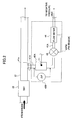
- FIG. 2 shows the configuration of a particulate matter concentration measuring apparatus 40PM (PM sensor) according to a first embodiment of the present invention. Note that components same as those of FIG. 1 are denoted by the same reference numerals and descriptions thereof are omitted.
- the particulate matter concentration measuring apparatus 40PM shown in FIG. 2 can be used to detect a failure occurring when particulate matter leaks to the downstream side of the particulate matter catching filter (DPF) 22 in the exhaust line 21 at a level more than or equal to a threshold and issue instructions for performing lighting, flashing, etc., of an alarm and a lamp.
- DPF particulate matter catching filter
- the exhaust line 21 of a diesel engine which is provided with the particulate matter catching filter (DPF) 22, is connected to an exhaust gas extraction line 41A having an exhaust gas extraction unit 41a at its one end on the downstream side of the particulate matter catching filter (DPF) 22.
- the exhaust gas extraction line 41A is connected in series to a particulate matter detection filter 42A, a flow meter 44 that measures a flow Q2 in the exhaust gas extraction line 41A, and a flow control valve 43.
- An end part on the downstream side of the exhaust gas extraction line 41A is connected to a unit such as a negative pressure tank and an air intake unit where a pressure is lower than the pressure of the inlet of the particulate matter detection filter 42A, whereby exhaust gas in the exhaust line 21 is suctioned into the particulate matter detection filter 42A.
- a suction pump is connected to the downstream side of the exhaust gas extraction line 41A, which enables the stable supply of exhaust gas to the particulate matter detection filter 42A.
- the particulate matter detection filter 42A is provided with the temperature measuring unit T1 that measures the temperature of the particulate matter detection filter 42A and a differential pressure measuring unit 42B.
- the differential pressure measuring unit 42B measures the differential pressure ⁇ P generated between the front side and the rear side of the particulate matter detection filter 42A.
- the exhaust gas extraction unit 41a has a flow passage cross-sectional area smaller than that of the exhaust line 21.
- differential pressure measuring unit 42B a diaphragm pressure gauge and known pressure meters of a gage type, a bellows type, a thermal type, and the like can be used.
- flow meter 44 known flow meters such as a hotwire flow meter and a venturi meter can be used.
- FIG. 3 shows an example of the particulate matter detection filter 42A.
- the particulate matter detection filter 42A has only a single cell 42b.
- the particulate matter detection filter 42A may have the plural cells 42b.
- the particulate matter detection filter 42A includes one or more gas passages 42a, which have a volume of 5% or less, e.g., 0.05 through 5% of the total volume of an exhaust gas passage in the particulate matter catching filter (DPF) 22, have a volume of 65 ml or less, e.g., 0.05 through 65 ml, or have a filtration area of 0.1 through 1000 cm 2 (preferably a filtration area of 1 through 10 cm 2 ), such that their cross sectional areas are formed in, e.g., rectangles and either ends of the gas passages 42a are closed (rear side is closed in the case of one cell).
- DPF particulate matter catching filter
- the cell 42b made of porous ceramics has the gas passage 42a with its one end opened and the other end closed.
- the exhaust gas introduced in the gas passage 42a passes through a cell wall made of porous ceramics and moves to an adjacent gas passage. At that time, particulate matter is caught at the inner wall surface of the cell 42b, which in turn forms a particulate matter layer 42c on the inner wall surface.
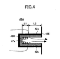
- FIG. 4 shows a modified example of the cell 42b shown in FIG. 3 .
- exhaust gas passes through a cell wall from the outside of the cell and flows into the gas passage 42a.
- the particulate matter layer 42c is accumulated on the outer surface of the cell 42b.
- the cells shown in FIG. 3 and those shown in FIG. 4 are alternately arranged so as to be adjacent to each other.
- the gas passage 42a and the cell 42b are not necessarily the same in size and in cross-sectional shape as the gas passage in the particulate matter catching filter (DPF) 22, but may be in any cross-sectional shape such as circle, square, octagon, and ellipse.
- the material of the porous ceramics constituting the particulate matter detection filter 42A (cell 42b) is not necessarily the same as that of the porous ceramics constituting the particulate matter catching filter (DPF) 22, and may not be made of ceramics.
- the total volume of the gas passage 42a is set to 5% or less of the total volume of the exhaust gas passage in the particulate matter catching filter (DPF) 22, have a volume of 65 ml or less, or have a filtration area of 0.1 through 1000 cm 2 (preferably a filtration area of 1 through 10 cm 2 ), a uniform soot layer is accumulated on the cell 42b. Accordingly, as described below, the accumulated amount of the particulate matter in the particulate matter catching filter (DPF) 22 can be easily and correctly measured.
- the particulate matter concentration measuring apparatus 40PM shown in FIG. 2 calculates the accumulated amount of the particulate matter caught by the particulate matter detection filter 42A based on the following formula 1.
- ⁇ ⁇ P ⁇ Q 2 ⁇ V trap ⁇ ⁇ + W s 2 ⁇ W s K w ⁇ ⁇ + 1 2 ⁇ K SOOT ⁇ ln ⁇ ⁇ ⁇ - 2 ⁇ W + 4 ⁇ FL 2 3 ⁇ 1 ⁇ - 2 ⁇ W 4 + 1 ⁇ 4 + ⁇ ⁇ Q 2 ⁇ ⁇ - W s 4 V trap 2 ⁇ ⁇ ⁇ W s 4 + 2 ⁇ ⁇ ⁇ L ⁇ 2
- ⁇ P is a differential pressure expressed in units of (Pa)
- ⁇ is a kinematic viscosity coefficient expressed in units of (Pa.s)
- Q is an exhaust gas flow expressed in units of (m 3 /s)
- ⁇ is the length of a side of a cell expressed in units of
- the mass “m soot” of the particulate matter caught by the particulate matter detection filter 42A (cell 42b) is found based on the following formula 2.
- W ⁇ - ⁇ 2 - m soot N cells ⁇ L ⁇ ⁇ soot 2
- m soot is the mass (g) of the caught particulate matter
- N cells is the opening number of a cell on the side of the inlet
- ⁇ soot is the density of the caught particulate matter.
- the caught amount "PM” (g/s) of the particulate matter per unit time can be found by dividing "m soot " by an elapsed time (s) since the previous regeneration of the particulate matter detection filter 42A.
- the particulate matter concentration measuring apparatus 40PM arranged on the downstream side of the particulate matter catching filter (DPF) 22 can immediately detect a failure occurring when the particulate matter leaks to the downstream side of the particulate matter catching filter (DPF) 22 in the exhaust line 21 at a level more than or equal to a threshold and issue instructions for performing lighting, flashing, etc., of an alarm and a lamp.
- the particulate matter detection filter 42A is accumulated on the particulate matter detection filter 42A with time. Therefore, as shown in FIG. 5 , a heater 42h is provided on the particulate matter detection filter 42A (cell 42b) according to the embodiment of the present invention.
- the particulate matter mainly containing C (carbon) and caught by the cell 42b is burned when the heater 42h is driven as occasion demands.
- the particulate matter detection filter 42A is regenerated.
- FIG. 5 is a diagram specifically showing the configuration of the particulate matter concentration measuring apparatus 40PM shown in FIG. 2 .
- the particulate matter detection filter 42A has one end constituting the exhaust gas extraction unit 41a and is stored in a housing connected to the exhaust gas extraction line 41A. Furthermore, a diaphragm pressure meter constituting the differential pressure measuring unit 42B is provided on the downstream side of the particulate matter detection filter 42A.
- the differential pressure measuring unit 42B has one end connected to the upstream side of the particulate matter detection filter 42A and the other end connected to the exhaust line extraction line 41A on the downstream side of the particulate matter detection filter 42A. With this configuration, the differential pressure measuring unit 42B can measure a differential pressure generated between the front side and the rear side of the cell 42b constituting the particulate matter detection filter 42A.
- the cell 42b has a length L from an end on the upstream side to an end on the downstream side in the flow direction of the exhaust gas passing through the cell 42b.
- a heating unit 42H composed of the heater 42h, which burns the particulate matter accumulated in the cell 42b to regenerate the particulate matter detection filter 42A, is densely arranged in an upstream-side region L1 making up, e.g., 30% of the cell constituting the particulate matter detection filter 42A on the upstream side.
- the heating unit 42H is not provided in a downstream-side region L2 on the downstream side of the upstream-side region L1.
- the heating unit 42H is provided so as to generate heat lower than that generated in the upstream-side region L1.
- FIG. 6 is a graph showing cases in which the proportion (%) of calorific value (electric power) input to the upstream-side region L1 of the cell 42b to that input to the entire cell is changed in various ways using the cells schematically shown in FIGS. 7A through 7D as the cell 42b. That is, FIG. 6 is a graph showing measurement errors between a particulate matter concentration in exhaust gas found according to the above formulae 1 through 3 and a particulate matter concentration (actual value) found by measuring particulate matter actually contained in exhaust gas. Note that in an experimental example shown in FIG. 6 , the upstream-side region L1 is set to make up 30% of the entire length L.
- the cell 42b has an entire length L of 15 mm and a square cross section, a side of which is 4.0 mm.
- the cell 42b has a wall thickness of 0.4 mm.
- the wire heater (kanthal wire heater) 42h is wound around only the upstream-side region L1 eight times as the heating unit 42H.
- the wire heater (kanthal wire heater) 42h is wound around the upstream-side region L1 twelve times and wound around the downstream-side region L2 six times.
- a resistance heater pattern 42hR is provided on the same cell 42b as those shown in FIGS. 7A and 7B by thermal-spraying or printing a Cr film or by sputtering a Pt film (see table 1 below).
- the resistance heater pattern 42hR is formed such that its width is shaped like a zigzag pattern having a width of 0.8 mm in the region L1 and shaped like a linear pattern having a width of 1.2 mm in the region L2.
- the same heater pattern 42hR is also provided at the opposing surface of the cell 42b.
- the proportion (%) of a calorific value input to the region L1 is varied by changing the width W1 in the region L1 and the width W2 in the region L2 of the resistance heater pattern 42hR to, e.g., 0.8 mm and 1.2 mm, or by changing the number of folding times of the zigzag pattern of the resistance heater pattern 42hR, the pitch of the zigzag pattern, or the thickness of heater patterning.
- the resistance heater pattern 42hR is formed in a linear shape in the regions L1 and L2 such that the widths W1 and W2 are different in the regions L1 and L2, respectively.
- the widths W1 and W2 are set to 0.93 mm and 3.7 mm, respectively.
- the number of winding times of the wire heater (kanthal wire heater) 42h is changed in the upstream-side region L1 and the downstream-side region L2 to vary the proportion (%) of the calorific value input to the upstream-side region L1 at the regeneration of the particulate matter detection filter 42A in various ways. Furthermore, exhaust gas is introduced in the cell 42b at a ratio of 0.141 1 per minute.
- exhaust gas from a diesel engine 11 to the exhaust line 21 is guided to a dilution tunnel 111 in which clean air is introduced, then diluted and cooled up to temperature below 52°C, and collected on a primary collecting filter 115 and a secondary collecting filter 116.
- the mass of the collected exhaust gas is measured by a microbalance to actually measure particulate matter contained in the exhaust gas.
- the measured particulate matter is converted into the concentration of the exhaust line 21 and recognized as an actual value.
- a calculated value (PM conc ) by the particulate matter concentration measuring apparatus 40PM distance from diesel engine (E/G) is 1.5 through 2.0) provided in the exhaust line 21 is compared with the actual value to find a measurement error. Note that according to configuration shown in FIG.
- the exhaust gas is suctioned by a blower 114 via a heat exchanger 112 and a critical flow venturi tube 113 after passing through the dilution tunnel 111. Furthermore, a blower 117 is also provided on the downstream side of the primary collecting filter 115 and the secondary collecting filter 116 to suction the exhaust gas.
- the calorific value is intensively input to the downstream-side region L2, i.e., if the proportion (%) of the calorific value input to the upstream-side region L1 making up 30% of the cell 42b on the upstream side is set to 40% of the calorific value input to the entire cell, it is found that the measurement error of the particulate matter concentration by the particulate matter concentration measuring apparatus 40PM approximates a great measurement error of ⁇ 11% or ⁇ 13% beyond ⁇ 10%.
- the proportion (%) of the calorific value input to the upstream-side region L1 making up 30% of the cell 42b on the upstream side is set to 50% through 70% of the calorific value input to the entire cell, it is found that the measurement error reduces to less than ⁇ 6% as shown in FIG. 6 .
- Table 1 shows regeneration rates and measurement errors when various materials are used to form the wire heater (kanthal wire heater) 42h or the resistance heater pattern 42hR in the cell 42b and the ratio of the calorific value input to the upstream-side region L1 and the downstream-side region L2 is changed in many ways.
- the "regeneration rate” refers to the amount of particulate matter remaining after the wire heater (kanthal wire heater) 42h or the resistance heater pattern 42hR is driven to burn the particulate matter accumulated in the cell 42b to regenerate the particulate matter detection filter 42A.
- the regeneration rate is found by comparing the initial weight of the cell 42b with the weight of the cell 42b after the regeneration of the particulate matter detection filter 42A. The measurement error is found as in the case shown in FIG. 6 .
- the measurement error increases as the regeneration rate reduces. This would lead to the fact that a reason for the measurement error in the graph shown in FIG. 6 is caused by the remaining of unburned particulate matter in the cell 42b even after the regeneration of the particulate matter detection filter 42A.
- the calorific value input is properly distributed to the upstream-side region L1 and the downstream-side region L2, i.e., if the proportion (%) of the calorific value input to the upstream-side region L1 to that input to the entire cell is 50% or more to 90% or less, the measurement error in the particulate matter concentration can be reduced to ⁇ 6% or less.
- the value of the measurement error increases again. This is because if no calorific value is input to the downstream-side region L2, burning of the particulate matter is relied only on the heat transmitted into the particulate matter collecting filter. Therefore, the heat applied to the downstream side L2 becomes reduced, which causes the insufficient burning of the particulate matter in the downstream side region L2 at the regeneration of the particulate matter detection filter 42A. As a result, the measurement error increases.
- the heating unit 42H is densely arranged in a part of the particulate matter detection filter 42A as shown in FIG. 5 or FIGS. 7A through 7D .
- This arrangement makes it possible to satisfactorily regenerate the particulate matter detection filter 42A and reduce the measurement error in the particulate matter concentration detection apparatus 40PM.
- the heating unit 42H can be made of a wire heater (kanthal wire), a Cr film, or a Pt film, but the material of the heating unit 42H is not limited to them.
- the resistance heater pattern 42hR can be formed by the use of various methods such as thermal spraying, sputtering, printing, and particularly screen printing.
- Examples of the wire heater include a kanthal wire, but other wire heaters may be used. Furthermore, the wire heater and the resistance pattern are also called resistance heaters. The resistance heaters are not limited to the wire heater and the resistance pattern.
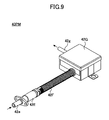
- a particulate matter concentration measuring apparatus 40PM according to the embodiment shown in FIG. 9 is inserted into the exhaust line 21 shown in FIG. 2 on the downstream side of the particulate matter catching filter (DPF) 22.
- the particulate matter concentration measuring apparatus 40PM has a pipe-shaped housing 42E that is provided with a fixed head unit 42e and made of heat-resistant metal such as stainless steel.
- the housing 42E includes the particulate matter detection filter 42A preferably made of porous ceramics such SiC (silicon carbide).
- the head unit 42e constitutes a part of the exhaust gas extraction line 41A inserted into the exhaust line 21.
- a flexible hose 42F through which exhaust gas passes is extended from the housing 42E.
- a control unit 42G storing the differential pressure measuring unit 42B and the flow measuring unit 44 is provided at an end on the downstream side of the flexible hose 42F.
- the exhaust gas having passed through the control unit 42G is exhausted to an exhaust pipe 42g.
- This configuration enables a desired particulate matter concentration measuring apparatus to be downsized.
- the particulate matter concentration measuring apparatus can be installed in any position of a vehicle as occasion demands.
- a pump 42P may be connected to the exhaust pipe 42g shown in FIG. 9 that exhausts the exhaust gas from the control unit 42G so as to forcibly exhaust the exhaust gas.
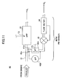
- FIG. 11 shows the configuration of an exhaust gas purification apparatus 60 of a diesel engine having a particulate matter detection apparatus 60PM (PM sensor) according to a second embodiment of the present invention.
- the exhaust gas purification apparatus 60 has a configuration similar to the configuration of the exhaust gas purification apparatus 20 shown in FIG. 1 . That is, the exhaust gas purification apparatus 60 has an exhaust gas extraction line 41A branched from the exhaust line 21 on the upstream side of the particulate matter catching filter (DPF) 22.
- DPF particulate matter catching filter
- exhaust gas that does not pass through the particulate matter catching filter (DPF) 22 is caught by a particulate matter detection filter 42A, and the following processing is performed in addition to the processing according to the above formulae 1 through 3 based on the amount of the particulate matter caught by the particulate matter detection filter 42A.
- the particulate matter concentration "PM conc " in the exhaust gas is the same both in the exhaust gas extraction line 41A and the exhaust line 21. Therefore, the amount (PM enter full filter (g/h)) of the particulate matter that passes through the exhaust line 21 is found according to the following formula 4.
- PM enter full filter g / h PM conc g / m 3 ⁇ Q ⁇ 1 m 3 / h where Q1 is an exhaust gas flow in the exhaust line 21.
- the amount of the particulate matter accumulated in the particulate matter catching filter (DPF) 22 can be estimated.
- Q1 is the flow of the exhaust gas that passes through the particulate matter catching filter (DPF) 22.
- Q1 may be found by actually measuring the flow of the exhaust gas or may be found by estimating the operating condition of an engine.
- a valve 43 is further provided in the exhaust gas extraction line 41A.
- the valve 43 is controlled by a flow meter 44 as in the case of the exhaust gas purification apparatus 20 shown in FIG. 1 , whereby the flow of the exhaust gas in the exhaust gas extraction line 41A is controlled to a predetermined value Q2.
- the heater 42h is provided on the particulate matter detection filter 42A (cell 42b) as described above.
- the heater 42h is driven by power from a driving line as occasion demands.
- the particulate matter mainly containing C (carbon) caught by the cell 42b is burned to regenerate the particulate matter detection filter 42A.
- This embodiment can also provide the same effects as those provided by the first embodiment.
- the flow measuring unit according to the embodiment can be eliminated if the flow of exhaust gas in the exhaust gas extraction line is known in advance.
- the temperature measuring unit may be eliminated provided that the characteristics of exhaust gas are constant.
- the valve can be eliminated if the flow of exhaust gas is correctly measured.
- a heating unit may be arranged inside the cell (on an inner periphery) or a heating unit (heater) may be arranged outside the cell (on an outer periphery).
Landscapes
- Chemical & Material Sciences (AREA)
- Engineering & Computer Science (AREA)
- Combustion & Propulsion (AREA)
- Mechanical Engineering (AREA)
- General Engineering & Computer Science (AREA)
- Dispersion Chemistry (AREA)
- Physics & Mathematics (AREA)
- Health & Medical Sciences (AREA)
- Life Sciences & Earth Sciences (AREA)
- Analytical Chemistry (AREA)
- Biochemistry (AREA)
- General Health & Medical Sciences (AREA)
- General Physics & Mathematics (AREA)
- Immunology (AREA)
- Pathology (AREA)
- Processes For Solid Components From Exhaust (AREA)
- Sampling And Sample Adjustment (AREA)
Abstract
Description
- The present invention relates to exhaust gas purification technologies of combustion engines and, in particular, to a particulate matter concentration measuring apparatus that measures the concentration of particulate matter (PM) contained in exhaust gas from a diesel engine.
- As a known apparatus that detects the concentration of particulate matter mainly containing C (carbon) in exhaust gas from a diesel engine, Patent Document 1 discloses a particulate matter concentration measuring apparatus 20PM (PM sensor) shown in
FIG. 1 . The particulate matter concentration measuring apparatus 20PM has asub-exhaust line 21A branched from anexhaust line 21; a particulatematter detection filter 22A arranged in thesub-exhaust line 21A; and a differentialpressure measuring unit 22B that measures a differential pressure generated between the inlet and the outlet of the particulatematter detection filter 22A. Thesub-exhaust line 21A is provided with aflow measuring unit 24 and a temperature measuring unit T1, and the particulatematter detection filter 22A is provided with a heater. - The particulate matter concentration measuring apparatus 20PM of Patent Document 1 measures a differential pressure ΔP generated between the front side and the rear side of the particulate
matter detection filter 22A, a temperature T of exhaust gas in thesub-exhaust line 21A, and a flow Q2 of the exhaust gas in thesub-exhaust line 21A. Based on the differential pressure ΔP, the temperature T, and the flow Q2 thus measured, the mass PM (g/h) of particulate matter caught by the particulatematter detection filter 22A per unit time is calculated. Furthermore, based on the mass PM (g/h) of the particulate matter, the concentration PMconc (g/m3) of the particulate matter in the exhaust gas is calculated. - In addition, Patent Document 1 discloses a particulate matter catching filter (DPF: diesel particulate filter) 22 made of porous ceramics in the
exhaust line 21 as a component of an exhaustgas purification apparatus 20. Thesub-exhaust line 21A of the particulate matter concentration measuring apparatus 20PM is connected to the upstream side of the exhaust gas flow of the particulatematter catching filter 22. Based on the concentration PMconc (g/m3) of the particulate matter in the exhaust gas specified and an operating status of an engine or the flow Q1 of the gas flowing in the particulate matter catching filter (DPF) 22 of theexhaust line 21, the mass PMenter full filter (g/h) of the particulate matter flowing into the diesel particulate filter (DPF) 22 is calculated.
Patent Document 1:EP1916394A1 - It is an object of the present invention to improve the measurement accuracy of a particulate matter measuring apparatus.
- According to an aspect of the present invention, there is provided a particulate matter concentration measuring apparatus that measures a particulate matter concentration in exhaust gas flowing in an exhaust line of a diesel engine. The apparatus includes an exhaust gas extraction line that is branched from the exhaust line and has a flow passage cross-sectional area smaller than a flow passage cross-sectional area of the exhaust line; a particulate matter detection filter that is provided in the exhaust gas extraction line and catches particulate matter; a heating unit that heats the caught particulate matter; and a differential pressure detection unit that detects a differential pressure generated between an inlet and an outlet of the particulate matter detection filter. The heating unit applies 50% or more of a calorific value for heating the particulate matter to an area making up 30% of the particulate matter detection filter on an upstream side of an exhaust gas flow.
- According to embodiments of the present invention, the uniform and effective regeneration of a particulate matter detection filter is ensured, which results in an improvement in the measurement accuracy of a particulate matter concentration.
- Other objects, features and advantages of the present invention will become more apparent from the following detailed description when read in conjunction with the accompanying drawings, in which:
-
FIG. 1 is a diagram showing the configuration of a conventional exhaust gas purification apparatus; -
FIG. 2 is a diagram showing the configuration of an exhaust gas purification apparatus using a particulate matter concentration measuring apparatus according to a first embodiment; -
FIG. 3 is a diagram for explaining the function of a particulate matter detection filter in the particulate matter concentration measuring apparatus according to the first embodiment; -
FIG. 4 is a diagram showing a modified example of the particulate matter detection filter in the particulate matter concentration measuring apparatus according to the first embodiment; -
FIG. 5 is a diagram specifically showing the configuration of the particulate matter concentration measuring apparatus according to the first embodiment; -
FIG. 6 is a graph showing a relationship between the proportion of a calorific value input to an upstream-side region of a cell and a measurement error in the particulate matter concentration measuring apparatus according to the first embodiment; -
FIG. 7A is a diagram showing an example of a heating unit according to a first embodiment; -
FIG. 7B is a diagram showing other example of the heating unit according to the first embodiment; -
FIG. 7C is a diagram showing still other example of the heating unit according to the first embodiment; -
FIG. 7D is a diagram showing yet other example of the heating unit according to the first embodiment; -
FIG. 8 is a diagram for explaining an experiment by which the actual value of a particulate matter concentration in the graph ofFIG. 6 is found; -
FIG. 9 is a diagram showing the whole of a particulate matter concentration measuring apparatus according to a second embodiment; -
FIG. 10 is a diagram showing a modified example of the particulate matter concentration measuring apparatus according to the first embodiment; -
FIG. 11 is a diagram showing the configuration of an exhaust gas purification apparatus using the particulate matter measuring apparatus according to the second embodiment; and -
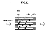
FIG. 12 is a diagram showing the configuration of the particulate matter detection filter according to the modified example according to the first embodiment. -
FIG. 2 shows the configuration of a particulate matter concentration measuring apparatus 40PM (PM sensor) according to a first embodiment of the present invention. Note that components same as those ofFIG. 1 are denoted by the same reference numerals and descriptions thereof are omitted. The particulate matter concentration measuring apparatus 40PM shown inFIG. 2 can be used to detect a failure occurring when particulate matter leaks to the downstream side of the particulate matter catching filter (DPF) 22 in theexhaust line 21 at a level more than or equal to a threshold and issue instructions for performing lighting, flashing, etc., of an alarm and a lamp. - Referring to
FIG. 2 , theexhaust line 21 of a diesel engine, which is provided with the particulate matter catching filter (DPF) 22, is connected to an exhaustgas extraction line 41A having an exhaustgas extraction unit 41a at its one end on the downstream side of the particulate matter catching filter (DPF) 22. The exhaustgas extraction line 41A is connected in series to a particulatematter detection filter 42A, aflow meter 44 that measures a flow Q2 in the exhaustgas extraction line 41A, and aflow control valve 43. An end part on the downstream side of the exhaustgas extraction line 41A is connected to a unit such as a negative pressure tank and an air intake unit where a pressure is lower than the pressure of the inlet of the particulatematter detection filter 42A, whereby exhaust gas in theexhaust line 21 is suctioned into the particulatematter detection filter 42A. This configuration produces the same effect as when a suction pump is connected to the downstream side of the exhaustgas extraction line 41A, which enables the stable supply of exhaust gas to the particulatematter detection filter 42A. - The particulate
matter detection filter 42A is provided with the temperature measuring unit T1 that measures the temperature of the particulatematter detection filter 42A and a differentialpressure measuring unit 42B. The differentialpressure measuring unit 42B measures the differential pressure ΔP generated between the front side and the rear side of the particulatematter detection filter 42A. The exhaustgas extraction unit 41a has a flow passage cross-sectional area smaller than that of theexhaust line 21. - Note that as the differential
pressure measuring unit 42B, a diaphragm pressure gauge and known pressure meters of a gage type, a bellows type, a thermal type, and the like can be used. As theflow meter 44, known flow meters such as a hotwire flow meter and a venturi meter can be used. -
FIG. 3 shows an example of the particulatematter detection filter 42A. In the example shown inFIG. 3 , the particulatematter detection filter 42A has only asingle cell 42b. However, as shown inFIG. 12 , the particulatematter detection filter 42A may have theplural cells 42b. - Referring to
FIG. 3 , the particulatematter detection filter 42A includes one ormore gas passages 42a, which have a volume of 5% or less, e.g., 0.05 through 5% of the total volume of an exhaust gas passage in the particulate matter catching filter (DPF) 22, have a volume of 65 ml or less, e.g., 0.05 through 65 ml, or have a filtration area of 0.1 through 1000 cm2 (preferably a filtration area of 1 through 10 cm2), such that their cross sectional areas are formed in, e.g., rectangles and either ends of thegas passages 42a are closed (rear side is closed in the case of one cell). - Referring to
FIG. 3 , thecell 42b made of porous ceramics has thegas passage 42a with its one end opened and the other end closed. The exhaust gas introduced in thegas passage 42a passes through a cell wall made of porous ceramics and moves to an adjacent gas passage. At that time, particulate matter is caught at the inner wall surface of thecell 42b, which in turn forms aparticulate matter layer 42c on the inner wall surface. -
FIG. 4 shows a modified example of thecell 42b shown inFIG. 3 . In the cell shown inFIG. 4 , exhaust gas passes through a cell wall from the outside of the cell and flows into thegas passage 42a. At that time, theparticulate matter layer 42c is accumulated on the outer surface of thecell 42b. In the filter shown inFIG. 12 , the cells shown inFIG. 3 and those shown inFIG. 4 are alternately arranged so as to be adjacent to each other. - Note that similar cells are also formed in the particulate matter catching filter (DPF) 22 described in
FIG. 1 . Thegas passage 42a and thecell 42b are not necessarily the same in size and in cross-sectional shape as the gas passage in the particulate matter catching filter (DPF) 22, but may be in any cross-sectional shape such as circle, square, octagon, and ellipse. Furthermore, the material of the porous ceramics constituting the particulatematter detection filter 42A (cell 42b) is not necessarily the same as that of the porous ceramics constituting the particulate matter catching filter (DPF) 22, and may not be made of ceramics. If the total volume of thegas passage 42a is set to 5% or less of the total volume of the exhaust gas passage in the particulate matter catching filter (DPF) 22, have a volume of 65 ml or less, or have a filtration area of 0.1 through 1000 cm2 (preferably a filtration area of 1 through 10 cm2), a uniform soot layer is accumulated on thecell 42b. Accordingly, as described below, the accumulated amount of the particulate matter in the particulate matter catching filter (DPF) 22 can be easily and correctly measured. - The particulate matter concentration measuring apparatus 40PM shown in
FIG. 2 calculates the accumulated amount of the particulate matter caught by the particulatematter detection filter 42A based on the following formula 1.
where "ΔP" is a differential pressure expressed in units of (Pa), "µ" is a kinematic viscosity coefficient expressed in units of (Pa.s), "Q" is an exhaust gas flow expressed in units of (m3/s), "α" is the length of a side of a cell expressed in units of (m), "ρ" is an exhaust gas density expressed in units of (g/m3), "Vtrap" is a filter volume expressed in units of (m3) "Ws" is a wall thickness expressed in units of (m), "Kw" is the gas permeability of a wall expressed in units of (m-1), "Ksoot" is the gas permeability of a caught particulate-matter-layer expressed in units of (m), "W" is the thickness of a caught particulate-matter-layer expressed in units of (m-1), "F" is a coefficient (= 28.454), "L" is an effective filter length expressed in units of (m), "β" is a Forchheimer coefficient of a porous wall expressed in units of (m-1), and "ξ" is a differential pressure due to passing through of gas in units of (Pa). - Next, the mass "msoot" of the particulate matter caught by the particulate
matter detection filter 42A (cell 42b) is found based on the followingformula 2.
where "msoot" is the mass (g) of the caught particulate matter, "Ncells" is the opening number of a cell on the side of the inlet, and "ρsoot" is the density of the caught particulate matter. - The caught amount "PM" (g/s) of the particulate matter per unit time can be found by dividing "msoot" by an elapsed time (s) since the previous regeneration of the particulate
matter detection filter 42A. - When the mass "PM" (g/s) of the particulate matter accumulated per unit time is found, a particulate matter concentration "PMconc" (g/m3) in exhaust gas is found based on the following formula 3 using a flow "Q2" (m3/s) of the exhaust gas passing through the particulate
matter detection filter 22A.
- As shown in
FIG. 2 , according to the embodiment of the present invention, the particulate matter concentration measuring apparatus 40PM arranged on the downstream side of the particulate matter catching filter (DPF) 22 can immediately detect a failure occurring when the particulate matter leaks to the downstream side of the particulate matter catching filter (DPF) 22 in theexhaust line 21 at a level more than or equal to a threshold and issue instructions for performing lighting, flashing, etc., of an alarm and a lamp. - Meanwhile, in the particulate matter concentration measuring apparatus 40PM in the configuration shown in
FIG. 2 , the particulate matter is accumulated on the particulatematter detection filter 42A with time. Therefore, as shown inFIG. 5 , aheater 42h is provided on the particulatematter detection filter 42A (cell 42b) according to the embodiment of the present invention. The particulate matter mainly containing C (carbon) and caught by thecell 42b is burned when theheater 42h is driven as occasion demands. Thus, the particulatematter detection filter 42A is regenerated. -
FIG. 5 is a diagram specifically showing the configuration of the particulate matter concentration measuring apparatus 40PM shown inFIG. 2 . - Referring to
FIG. 5 , the particulatematter detection filter 42A has one end constituting the exhaustgas extraction unit 41a and is stored in a housing connected to the exhaustgas extraction line 41A. Furthermore, a diaphragm pressure meter constituting the differentialpressure measuring unit 42B is provided on the downstream side of the particulatematter detection filter 42A. The differentialpressure measuring unit 42B has one end connected to the upstream side of the particulatematter detection filter 42A and the other end connected to the exhaustline extraction line 41A on the downstream side of the particulatematter detection filter 42A. With this configuration, the differentialpressure measuring unit 42B can measure a differential pressure generated between the front side and the rear side of thecell 42b constituting the particulatematter detection filter 42A. - The
cell 42b has a length L from an end on the upstream side to an end on the downstream side in the flow direction of the exhaust gas passing through thecell 42b. In the particulate matter concentration measuring apparatus 40PM shown inFIG. 5 , aheating unit 42H composed of theheater 42h, which burns the particulate matter accumulated in thecell 42b to regenerate the particulatematter detection filter 42A, is densely arranged in an upstream-side region L1 making up, e.g., 30% of the cell constituting the particulatematter detection filter 42A on the upstream side. In this configuration, theheating unit 42H is not provided in a downstream-side region L2 on the downstream side of the upstream-side region L1. Alternatively, theheating unit 42H is provided so as to generate heat lower than that generated in the upstream-side region L1. -
FIG. 6 is a graph showing cases in which the proportion (%) of calorific value (electric power) input to the upstream-side region L1 of thecell 42b to that input to the entire cell is changed in various ways using the cells schematically shown inFIGS. 7A through 7D as thecell 42b. That is,FIG. 6 is a graph showing measurement errors between a particulate matter concentration in exhaust gas found according to the above formulae 1 through 3 and a particulate matter concentration (actual value) found by measuring particulate matter actually contained in exhaust gas. Note that in an experimental example shown inFIG. 6 , the upstream-side region L1 is set to make up 30% of the entire length L. - Referring to samples shown in
FIGS. 7A and 7B , thecell 42b has an entire length L of 15 mm and a square cross section, a side of which is 4.0 mm. In thecell 42b, a gas passage having a square cross section, a side of which is 3.2 mm, is provided as thegas passage 42a. Thecell 42b has a wall thickness of 0.4 mm. In the example of the cell shown inFIG. 7A , the wire heater (kanthal wire heater) 42h is wound around only the upstream-side region L1 eight times as theheating unit 42H. On the other hand, in the cell shown inFIG. 7B , the wire heater (kanthal wire heater) 42h is wound around the upstream-side region L1 twelve times and wound around the downstream-side region L2 six times. - In the samples shown in
FIGS. 7C and7D , a resistance heater pattern 42hR is provided on thesame cell 42b as those shown inFIGS. 7A and 7B by thermal-spraying or printing a Cr film or by sputtering a Pt film (see table 1 below). In the example of the sample shown inFIG. 7C , the resistance heater pattern 42hR is formed such that its width is shaped like a zigzag pattern having a width of 0.8 mm in the region L1 and shaped like a linear pattern having a width of 1.2 mm in the region L2. The same heater pattern 42hR is also provided at the opposing surface of thecell 42b. In the sample shown inFIG. 7C , the proportion (%) of a calorific value input to the region L1 is varied by changing the width W1 in the region L1 and the width W2 in the region L2 of the resistance heater pattern 42hR to, e.g., 0.8 mm and 1.2 mm, or by changing the number of folding times of the zigzag pattern of the resistance heater pattern 42hR, the pitch of the zigzag pattern, or the thickness of heater patterning. - In the sample shown in
FIG. 7D , the resistance heater pattern 42hR is formed in a linear shape in the regions L1 and L2 such that the widths W1 and W2 are different in the regions L1 and L2, respectively. In an example, the widths W1 and W2 are set to 0.93 mm and 3.7 mm, respectively. - In the experimental example shown in
FIG. 6 described below, the number of winding times of the wire heater (kanthal wire heater) 42h is changed in the upstream-side region L1 and the downstream-side region L2 to vary the proportion (%) of the calorific value input to the upstream-side region L1 at the regeneration of the particulatematter detection filter 42A in various ways. Furthermore, exhaust gas is introduced in thecell 42b at a ratio of 0.141 1 per minute. - As shown in
FIG. 8 , exhaust gas from adiesel engine 11 to theexhaust line 21 is guided to adilution tunnel 111 in which clean air is introduced, then diluted and cooled up to temperature below 52°C, and collected on aprimary collecting filter 115 and asecondary collecting filter 116. The mass of the collected exhaust gas is measured by a microbalance to actually measure particulate matter contained in the exhaust gas. The measured particulate matter is converted into the concentration of theexhaust line 21 and recognized as an actual value. A calculated value (PMconc) by the particulate matter concentration measuring apparatus 40PM (distance from diesel engine (E/G) is 1.5 through 2.0) provided in theexhaust line 21 is compared with the actual value to find a measurement error. Note that according to configuration shown inFIG. 8 , the exhaust gas is suctioned by ablower 114 via aheat exchanger 112 and a criticalflow venturi tube 113 after passing through thedilution tunnel 111. Furthermore, ablower 117 is also provided on the downstream side of theprimary collecting filter 115 and thesecondary collecting filter 116 to suction the exhaust gas. - Referring back to the graph shown in
FIG. 6 , if the calorific value is intensively input to the downstream-side region L2, i.e., if the proportion (%) of the calorific value input to the upstream-side region L1 making up 30% of thecell 42b on the upstream side is set to 40% of the calorific value input to the entire cell, it is found that the measurement error of the particulate matter concentration by the particulate matter concentration measuring apparatus 40PM approximates a great measurement error of ±11% or ±13% beyond ±10%. - Conversely, if the proportion (%) of the calorific value input to the upstream-side region L1 making up 30% of the
cell 42b on the upstream side is set to 50% through 70% of the calorific value input to the entire cell, it is found that the measurement error reduces to less than ±6% as shown inFIG. 6 . - On the other hand, if the calorific value input to the upstream-side region L1 making up 30% of the
cell 42b on the upstream side is set to 100% of the calorific value input to the entire cell, it is found that the measurement error increases again, exceeding ±6%. - Table 1 shows regeneration rates and measurement errors when various materials are used to form the wire heater (kanthal wire heater) 42h or the resistance heater pattern 42hR in the
cell 42b and the ratio of the calorific value input to the upstream-side region L1 and the downstream-side region L2 is changed in many ways.TABLE 1 MEASURED AFTER REGENERATION PROPORTION (%) OF THE CALORIFIC VALUE INPUT TO FRONT 30% OF TOTAL LENGTH OF CELL (L1)PROPORTION (%) OF THE CALORIFIC VALUE INPUT TO FRONT 30% OF TOTAL LENGTH OF CELL (L2)FORMING METHOD MATER1AL REGENERATION
RATE [%]MEASUREMENT
ERROR [±%]EXAMPLE 1 70 30 THERMAL
SPRAYINGCr 96 3 EXAMPLE 2 50 50 THERMAL
SPRAYINGCr 87 5 EXAMPLE 3 60 40 THERMAL
SPRAYINGCr 93 5 EXAMPLE 4 100 0 THERMAL
SPRAYINGCr 85 7 EXAMPLE 5 60 40 WINDING KANTHAL
WIRE 90 5 EXAMPLE 6 60 40 SPUTTERING Pt 92 5 EXAMPLE 7 60 40 PRINTING Cr 93 5 EXAMPLE 8 90 10 THERMAL
SPRAYINGCr 90 5 COMPARATIVE
EXAMPLE 140 60 THERMAL
SPRAYINGCr 78 11 COMPARATIVE
EXAMPLE 240 60 WINDING KANTHAL
WIRE75 13 - Referring to table 1, the "regeneration rate" refers to the amount of particulate matter remaining after the wire heater (kanthal wire heater) 42h or the resistance heater pattern 42hR is driven to burn the particulate matter accumulated in the
cell 42b to regenerate the particulatematter detection filter 42A. The regeneration rate is found by comparing the initial weight of thecell 42b with the weight of thecell 42b after the regeneration of the particulatematter detection filter 42A. The measurement error is found as in the case shown inFIG. 6 . - As shown in table 1, the measurement error increases as the regeneration rate reduces. This would lead to the fact that a reason for the measurement error in the graph shown in
FIG. 6 is caused by the remaining of unburned particulate matter in thecell 42b even after the regeneration of the particulatematter detection filter 42A. - Particularly, in the experimental example in the graph shown in
FIG. 6 in which the calorific value input to the upstream-side region L1 of the cell is 40% of the calorific value input to the entire cell, 60% of the calorific value input to the entire cell is input to the downstream-side region L2. As a result, the particulate matter in the upstream-side region L1 is not sufficiently burned, and the unburned particulate matter remains even in the downstream-side region L2. For this reason, the large measurement error occurs in the measurement of the particulate matter concentration in the experimental example. - Conversely, if the calorific value input is properly distributed to the upstream-side region L1 and the downstream-side region L2, i.e., if the proportion (%) of the calorific value input to the upstream-side region L1 to that input to the entire cell is 50% or more to 90% or less, the measurement error in the particulate matter concentration can be reduced to ±6% or less.
- Furthermore, if 100% of the calorific value is input to only the upstream-side region L1, the value of the measurement error increases again. This is because if no calorific value is input to the downstream-side region L2, burning of the particulate matter is relied only on the heat transmitted into the particulate matter collecting filter. Therefore, the heat applied to the downstream side L2 becomes reduced, which causes the insufficient burning of the particulate matter in the downstream side region L2 at the regeneration of the particulate
matter detection filter 42A. As a result, the measurement error increases. - According to the embodiment of the present invention, the
heating unit 42H is densely arranged in a part of the particulatematter detection filter 42A as shown inFIG. 5 orFIGS. 7A through7D . This arrangement makes it possible to satisfactorily regenerate the particulatematter detection filter 42A and reduce the measurement error in the particulate matter concentration detection apparatus 40PM. - Furthermore, as shown in table 1, the
heating unit 42H can be made of a wire heater (kanthal wire), a Cr film, or a Pt film, but the material of theheating unit 42H is not limited to them. Moreover, as shown in table 1, the resistance heater pattern 42hR can be formed by the use of various methods such as thermal spraying, sputtering, printing, and particularly screen printing. - Examples of the wire heater include a kanthal wire, but other wire heaters may be used. Furthermore, the wire heater and the resistance pattern are also called resistance heaters. The resistance heaters are not limited to the wire heater and the resistance pattern.
- Note that a particulate matter concentration measuring apparatus 40PM according to the embodiment shown in
FIG. 9 is inserted into theexhaust line 21 shown inFIG. 2 on the downstream side of the particulate matter catching filter (DPF) 22. The particulate matter concentration measuring apparatus 40PM has a pipe-shapedhousing 42E that is provided with a fixedhead unit 42e and made of heat-resistant metal such as stainless steel. Thehousing 42E includes the particulatematter detection filter 42A preferably made of porous ceramics such SiC (silicon carbide). Here, thehead unit 42e constitutes a part of the exhaustgas extraction line 41A inserted into theexhaust line 21. - As shown in
FIG. 9 , aflexible hose 42F through which exhaust gas passes is extended from thehousing 42E. At an end on the downstream side of theflexible hose 42F, acontrol unit 42G storing the differentialpressure measuring unit 42B and theflow measuring unit 44 is provided. The exhaust gas having passed through thecontrol unit 42G is exhausted to anexhaust pipe 42g. - This configuration enables a desired particulate matter concentration measuring apparatus to be downsized. As a result, the particulate matter concentration measuring apparatus can be installed in any position of a vehicle as occasion demands.
- As shown in
FIG. 10 , according to the embodiment, apump 42P may be connected to theexhaust pipe 42g shown inFIG. 9 that exhausts the exhaust gas from thecontrol unit 42G so as to forcibly exhaust the exhaust gas. With this configuration, even if thehead unit 42e is provided in an atmosphere in which the exhaust gas does not flow, the exhaust gas is suctioned by a negative pressure generated by thepump 42P, whereby the particulate matter concentration can be desirably measured. -
FIG. 11 shows the configuration of an exhaustgas purification apparatus 60 of a diesel engine having a particulate matter detection apparatus 60PM (PM sensor) according to a second embodiment of the present invention. - Referring to
FIG. 11 , the exhaustgas purification apparatus 60 has a configuration similar to the configuration of the exhaustgas purification apparatus 20 shown inFIG. 1 . That is, the exhaustgas purification apparatus 60 has an exhaustgas extraction line 41A branched from theexhaust line 21 on the upstream side of the particulate matter catching filter (DPF) 22. - In the configuration shown in
FIG. 11 , exhaust gas that does not pass through the particulate matter catching filter (DPF) 22 is caught by a particulatematter detection filter 42A, and the following processing is performed in addition to the processing according to the above formulae 1 through 3 based on the amount of the particulate matter caught by the particulatematter detection filter 42A. - The particulate matter concentration "PMconc" in the exhaust gas is the same both in the exhaust
gas extraction line 41A and theexhaust line 21. Therefore, the amount (PMenter full filter (g/h)) of the particulate matter that passes through theexhaust line 21 is found according to the following formula 4.
where Q1 is an exhaust gas flow in theexhaust line 21. - According to this formula, the amount of the particulate matter accumulated in the particulate matter catching filter (DPF) 22 can be estimated. Note, however, that Q1 is the flow of the exhaust gas that passes through the particulate matter catching filter (DPF) 22. Q1 may be found by actually measuring the flow of the exhaust gas or may be found by estimating the operating condition of an engine.
- In the configuration shown in
FIG. 11 , avalve 43 is further provided in the exhaustgas extraction line 41A. Thevalve 43 is controlled by aflow meter 44 as in the case of the exhaustgas purification apparatus 20 shown inFIG. 1 , whereby the flow of the exhaust gas in the exhaustgas extraction line 41A is controlled to a predetermined value Q2. - In this configuration, however, the particulate matter is accumulated on the particulate
matter detection filter 42A with time. Therefore, the particulatematter detection filter 42A is regenerated. - According to this embodiment, the
heater 42h is provided on the particulatematter detection filter 42A (cell 42b) as described above. Theheater 42h is driven by power from a driving line as occasion demands. Thus, the particulate matter mainly containing C (carbon) caught by thecell 42b is burned to regenerate the particulatematter detection filter 42A. - This embodiment can also provide the same effects as those provided by the first embodiment.
- The present invention is not limited to the specifically disclosed embodiment, but variations and modifications may be made without departing from the scope of the present invention. For example, the flow measuring unit according to the embodiment can be eliminated if the flow of exhaust gas in the exhaust gas extraction line is known in advance. Furthermore, the temperature measuring unit may be eliminated provided that the characteristics of exhaust gas are constant. Moreover, the valve can be eliminated if the flow of exhaust gas is correctly measured.
- Furthermore, as shown in
FIG. 4 , a heating unit (heater) may be arranged inside the cell (on an inner periphery) or a heating unit (heater) may be arranged outside the cell (on an outer periphery).
Claims (14)
- A particulate matter concentration measuring apparatus that measures a particulate matter concentration in exhaust gas flowing in an exhaust line of a diesel engine, the apparatus comprising:an exhaust gas extraction line that is branched from the exhaust line and has a flow passage cross-sectional area smaller than a flow passage cross-sectional area of the exhaust line;a particulate matter detection filter that is provided in the exhaust gas extraction line and catches particulate matter;a heating unit that heats the caught particulate matter; anda differential pressure detection unit that detects a differential pressure generated between an inlet and an outlet of the particulate matter detection filter; characterized in thatthe heating unit applies 50% or more of a calorific value for heating the particulate matter to an area making up 30% of the particulate matter detection filter on an upstream side of an exhaust gas flow.
- The particulate matter concentration measuring apparatus according to claim 1,
characterized in that
the heating unit applies 50% or more to 90% or less of the calorific value for heating the particulate matter to the area making up 30% of the particulate matter detection filter on the upstream side of the exhaust gas flow. - The particulate matter concentration measuring apparatus according to claim 1 or 2,
characterized in that
the particulate matter detection filter has at least a cylindrical part extending in an axial direction toward a downstream side of the exhaust gas flow and a bottom part arranged on the downstream side of the exhaust gas flow in the cylindrical part, and the heating unit is provided on an outer periphery of the cylindrical part. - The particulate matter concentration measuring apparatus according to claim 1 or 2,
characterized in that
the particulate matter detection filter has at least a cylindrical part extending in an axial direction toward a downstream side of the exhaust gas flow and a bottom part arranged on the upstream side of the exhaust gas flow in the cylindrical part, and the heating unit is provided on an inner periphery of the cylindrical part. - The particulate matter concentration measuring apparatus according to any one of claims 1 through 4, characterized in that
the heating unit comprises a resistance heater wound around the particulate matter detection filter. - The particulate matter concentration measuring apparatus according to any one of claims 1 through 4, characterized in that
the heating unit comprises a resistance heater printed on the particulate matter detection filter. - The particulate matter concentration measuring apparatus according to any one of claims 1 through 4, characterized in that
the heating unit comprises a resistance heater thermally sprayed on the particulate matter detection filter. - The particulate matter concentration measuring apparatus according to any one of claims 1 through 4, characterized in that
the heating unit comprises a resistance heater sputtered on the particulate matter detection filter. - The particulate matter concentration measuring apparatus according to any one of claims 1 through 8, further comprising
a flow measuring unit that is inserted in the exhaust gas extraction line and measures an exhaust gas flow in the exhaust gas extraction line. - The particulate matter concentration measuring apparatus according to claim 9, further comprising:a flow control valve that is inserted in the exhaust gas extraction line and controls the exhaust gas flow in the exhaust gas extraction line; anda control unit that controls the flow control valve based on the exhaust gas flow measured by the flow measuring unit and controls the exhaust gas flow in the exhaust gas extraction line to a predetermined value.
- The particulate matter concentration measuring apparatus according to any one of claims 1 through 10, further comprising
a pump arranged on the downstream side of the exhaust gas flow in the particulate matter detection filter. - The particulate matter concentration measuring apparatus according to any one of claims 1 through 11, characterized in that
a particulate matter catching filter having a capacity greater than a capacity of the particulate matter detection filter is arranged in the exhaust line. - The particulate matter concentration measuring apparatus according to claim 12,
characterized in that
the exhaust gas extraction line is connected to the downstream side of the particulate matter catching filter in the exhaust line. - The particulate matter concentration measuring apparatus according to claim 12,
characterized in that
the exhaust gas extraction line is connected to the upstream side of the particulate matter catching filter in the exhaust line.
Applications Claiming Priority (1)
| Application Number | Priority Date | Filing Date | Title |
|---|---|---|---|
| PCT/JP2009/056749 WO2010113294A1 (en) | 2009-03-31 | 2009-03-31 | Particulate matter concentration measuring apparatus |
Publications (2)
| Publication Number | Publication Date |
|---|---|
| EP2237017A2 true EP2237017A2 (en) | 2010-10-06 |
| EP2237017A3 EP2237017A3 (en) | 2015-07-15 |
Family
ID=41506449
Family Applications (1)
| Application Number | Title | Priority Date | Filing Date |
|---|---|---|---|
| EP09014752.1A Withdrawn EP2237017A3 (en) | 2009-03-31 | 2009-11-26 | Particulate matter concentration measuring apparatus |
Country Status (3)
| Country | Link |
|---|---|
| US (1) | US8234858B2 (en) |
| EP (1) | EP2237017A3 (en) |
| WO (1) | WO2010113294A1 (en) |
Cited By (3)
| Publication number | Priority date | Publication date | Assignee | Title |
|---|---|---|---|---|
| WO2012054876A3 (en) * | 2010-10-22 | 2012-07-12 | Magee Scientific Corporation | Method and analyzer for determining the content of carbon-containing particles filtered from an air stream |
| CN103234881A (en) * | 2013-04-09 | 2013-08-07 | 安徽省安光环境光学工程技术研究中心有限公司 | An air particle monitor |
| CN104655533A (en) * | 2013-11-18 | 2015-05-27 | 中山欧麦克仪器设备有限公司 | Two-channel automatic particulate monitoring device |
Families Citing this family (13)
| Publication number | Priority date | Publication date | Assignee | Title |
|---|---|---|---|---|
| WO2010113292A1 (en) * | 2009-03-31 | 2010-10-07 | イビデン株式会社 | Particulate matter concentration measuring apparatus |
| WO2010113295A1 (en) * | 2009-03-31 | 2010-10-07 | イビデン株式会社 | Particulate matter concentration measuring device |
| CA2864134C (en) * | 2011-02-14 | 2021-02-09 | The Administrators Of The Tulane Educational Fund | A device and method for monitoring the presence, onset and evolution of particulates in chemically or physically reacting systems |
| AT509962B1 (en) * | 2011-09-12 | 2015-05-15 | Avl List Gmbh | METHOD AND DEVICE FOR DETERMINING THE CONCENTRATION OF AEROSOLS IN HOT GASES, ESPECIALLY IN EXHAUST GASES FROM COMBUSTION ENGINES |
| CN103487357A (en) * | 2013-10-12 | 2014-01-01 | 杭州富铭环境科技有限公司 | System and method for monitoring atmospheric floating dust on line |
| CN104237087B (en) * | 2014-08-12 | 2016-07-06 | 浙江工商大学 | The method of gas particles substrate concentration detector and use |
| US9551259B1 (en) * | 2015-08-26 | 2017-01-24 | Ford Global Technologies, Llc | Method and system for diesel particulate filter diagnostics |
| GB2542827B (en) * | 2015-09-30 | 2019-10-02 | Smiths Detection Watford Ltd | Sampling method and apparatus with heating to vapourise components |
| US9645068B2 (en) * | 2015-10-13 | 2017-05-09 | Ford Global Technologies, Llc | Method and system for particulate filter leakage detection |
| US9551262B1 (en) * | 2015-10-13 | 2017-01-24 | Ford Global Technologies, Llc | Method and system for particulate filter leakage detection |
| IT201700092925A1 (en) * | 2017-08-10 | 2019-02-10 | St Microelectronics Srl | PROCEDURE FOR MANAGEMENT OF EXHAUST GAS IN INTERNAL COMBUSTION ENGINES, SYSTEM, ENGINE, VEHICLE AND CORRESPONDENT COMPUTER PRODUCT |
| CN113758842A (en) * | 2021-06-03 | 2021-12-07 | 杭州明瑞智能检测科技有限公司 | Oil smoke particulate matter detection device with heating function and detection method thereof |
| CN113899670A (en) * | 2021-10-26 | 2022-01-07 | 张家港朗亿机电设备有限公司 | Oil smoke particulate matter concentration detection device |
Family Cites Families (18)
| Publication number | Priority date | Publication date | Assignee | Title |
|---|---|---|---|---|
| US4319896A (en) * | 1979-03-15 | 1982-03-16 | Texaco Inc. | Smoke filter rejuvenation system |
| JP3064322B2 (en) * | 1990-03-07 | 2000-07-12 | 株式会社デンソー | Exhaust gas purification device for internal combustion engine |
| EP0477394A1 (en) * | 1990-09-24 | 1992-04-01 | Siemens Aktiengesellschaft | Electric heating device with a predetermined temperature profile, especially for exhaust gas sensors |
| EP0572827A1 (en) * | 1992-06-03 | 1993-12-08 | Corning Incorporated | Heated cellular substrates |
| JPH06264722A (en) * | 1993-03-12 | 1994-09-20 | Toyota Autom Loom Works Ltd | Filter device |
| JP3059322B2 (en) * | 1993-06-30 | 2000-07-04 | 株式会社いすゞセラミックス研究所 | Diesel Particulate Filter |
| EP0754267B1 (en) * | 1994-04-06 | 1998-07-15 | Minnesota Mining And Manufacturing Company | Electrically regenerable diesel particulate filter cartridge and filter |
| JP3589308B2 (en) * | 1994-07-14 | 2004-11-17 | イビデン株式会社 | Exhaust gas purification device |
| JP3258910B2 (en) | 1996-06-12 | 2002-02-18 | 京楽産業株式会社 | Mounting structure of switch box for removing balls in pachinko machine |
| JP4186425B2 (en) * | 2001-03-26 | 2008-11-26 | いすゞ自動車株式会社 | Soot particle detection sensor, diesel particulate filter device using the same, and control method therefor |
| JP4606965B2 (en) * | 2005-03-07 | 2011-01-05 | 本田技研工業株式会社 | Exhaust gas purification device for internal combustion engine |
| DE102006048045A1 (en) * | 2006-10-11 | 2008-04-17 | Daimler Ag | Emission control system for an internal combustion engine |
| US7658064B2 (en) * | 2006-10-17 | 2010-02-09 | Ibiden Co., Ltd. | Exhaust gas purifying apparatus |
| ATE460571T1 (en) * | 2006-10-17 | 2010-03-15 | Ibiden Co Ltd | EXHAUST GAS PURIFICATION DEVICE |
| ATE426736T1 (en) * | 2006-10-17 | 2009-04-15 | Ibiden Co Ltd | EXHAUST GAS PURIFICATION DEVICE AND CORRESPONDING METHOD AND A METHOD FOR MEASURING THE PARTICLES |
| EP1914536A1 (en) * | 2006-10-17 | 2008-04-23 | Ibiden Co., Ltd. | Particulate matter sensor for exhaust gas purifying apparatus |
| US8292987B2 (en) * | 2007-09-18 | 2012-10-23 | GM Global Technology Operations LLC | Inductively heated particulate matter filter regeneration control system |
| US20110179778A1 (en) * | 2010-01-27 | 2011-07-28 | Gm Global Technology Operations, Inc. | Method and apparatus for exhaust gas aftertreatment from an internal combustion engine |
-
2009
- 2009-03-31 WO PCT/JP2009/056749 patent/WO2010113294A1/en not_active Ceased
- 2009-11-26 EP EP09014752.1A patent/EP2237017A3/en not_active Withdrawn
-
2010
- 2010-01-27 US US12/694,288 patent/US8234858B2/en active Active
Cited By (3)
| Publication number | Priority date | Publication date | Assignee | Title |
|---|---|---|---|---|
| WO2012054876A3 (en) * | 2010-10-22 | 2012-07-12 | Magee Scientific Corporation | Method and analyzer for determining the content of carbon-containing particles filtered from an air stream |
| CN103234881A (en) * | 2013-04-09 | 2013-08-07 | 安徽省安光环境光学工程技术研究中心有限公司 | An air particle monitor |
| CN104655533A (en) * | 2013-11-18 | 2015-05-27 | 中山欧麦克仪器设备有限公司 | Two-channel automatic particulate monitoring device |
Also Published As
| Publication number | Publication date |
|---|---|
| US20100242455A1 (en) | 2010-09-30 |
| US8234858B2 (en) | 2012-08-07 |
| EP2237017A3 (en) | 2015-07-15 |
| WO2010113294A1 (en) | 2010-10-07 |
Similar Documents
| Publication | Publication Date | Title |
|---|---|---|
| US8234858B2 (en) | Particulate matter concentration measuring apparatus | |
| EP2236786B1 (en) | Particulate matter concentration measuring apparatus | |
| EP2237016A2 (en) | Particulate matter concentration measuring apparatus | |
| US8127592B2 (en) | Particulate matter detection sensor | |
| EP1921289B1 (en) | Exhaust gas purifying apparatus for measuring particles | |
| US7891176B2 (en) | Exhaust gas purifying apparatus | |
| EP2237015A2 (en) | Particulate matter concentration measuring apparatus | |
| US7658064B2 (en) | Exhaust gas purifying apparatus | |
| US7866146B2 (en) | Exhaust gas purifying apparatus, exhaust gas purifying method, and particulate matter measuring method | |
| EP0411445B1 (en) | Regeneratable particulate filter trap system | |
| US20080087101A1 (en) | Particulate matter sensor | |
| JP2012037237A (en) | Particulate concentration measuring apparatus | |
| JP2011133449A (en) | Particle concentration measuring device | |
| JP2012062755A (en) | Fine particle concentration measuring device | |
| JP2011075538A (en) | Apparatus for measurement of fine particle concentration | |
| JPH11264313A (en) | Heating element for fluid heating and exhaust gas purification device using the same |
Legal Events
| Date | Code | Title | Description |
|---|---|---|---|
| PUAI | Public reference made under article 153(3) epc to a published international application that has entered the european phase |
Free format text: ORIGINAL CODE: 0009012 |
|
| 17P | Request for examination filed |
Effective date: 20091126 |
|
| AK | Designated contracting states |
Kind code of ref document: A2 Designated state(s): AT BE BG CH CY CZ DE DK EE ES FI FR GB GR HR HU IE IS IT LI LT LU LV MC MK MT NL NO PL PT RO SE SI SK SM TR |
|
| AX | Request for extension of the european patent |
Extension state: AL BA RS |
|
| PUAL | Search report despatched |
Free format text: ORIGINAL CODE: 0009013 |
|
| AK | Designated contracting states |
Kind code of ref document: A3 Designated state(s): AT BE BG CH CY CZ DE DK EE ES FI FR GB GR HR HU IE IS IT LI LT LU LV MC MK MT NL NO PL PT RO SE SI SK SM TR |
|
| AX | Request for extension of the european patent |
Extension state: AL BA RS |
|
| RIC1 | Information provided on ipc code assigned before grant |
Ipc: F01N 3/031 20060101ALN20150609BHEP Ipc: G01N 15/06 20060101AFI20150609BHEP Ipc: F01N 13/00 20100101ALI20150609BHEP Ipc: F01N 3/021 20060101ALN20150609BHEP |
|
| 17Q | First examination report despatched |
Effective date: 20160407 |
|
| STAA | Information on the status of an ep patent application or granted ep patent |
Free format text: STATUS: THE APPLICATION IS DEEMED TO BE WITHDRAWN |
|
| 18D | Application deemed to be withdrawn |
Effective date: 20160818 |